US10896834B2 - Wafer shipper with stacked support rings - Google Patents
Wafer shipper with stacked support rings Download PDFInfo
- Publication number
- US10896834B2 US10896834B2 US15/120,973 US201515120973A US10896834B2 US 10896834 B2 US10896834 B2 US 10896834B2 US 201515120973 A US201515120973 A US 201515120973A US 10896834 B2 US10896834 B2 US 10896834B2
- Authority
- US
- United States
- Prior art keywords
- wafer
- support ring
- wafer support
- stack
- uppermost
- Prior art date
- Legal status (The legal status is an assumption and is not a legal conclusion. Google has not performed a legal analysis and makes no representation as to the accuracy of the status listed.)
- Active, expires
Links
Images


Classifications
-
- H—ELECTRICITY
- H01—ELECTRIC ELEMENTS
- H01L—SEMICONDUCTOR DEVICES NOT COVERED BY CLASS H10
- H01L21/00—Processes or apparatus adapted for the manufacture or treatment of semiconductor or solid state devices or of parts thereof
- H01L21/67—Apparatus specially adapted for handling semiconductor or electric solid state devices during manufacture or treatment thereof; Apparatus specially adapted for handling wafers during manufacture or treatment of semiconductor or electric solid state devices or components ; Apparatus not specifically provided for elsewhere
- H01L21/673—Apparatus specially adapted for handling semiconductor or electric solid state devices during manufacture or treatment thereof; Apparatus specially adapted for handling wafers during manufacture or treatment of semiconductor or electric solid state devices or components ; Apparatus not specifically provided for elsewhere using specially adapted carriers or holders; Fixing the workpieces on such carriers or holders
- H01L21/6735—Closed carriers
- H01L21/67386—Closed carriers characterised by the construction of the closed carrier
-
- H—ELECTRICITY
- H01—ELECTRIC ELEMENTS
- H01L—SEMICONDUCTOR DEVICES NOT COVERED BY CLASS H10
- H01L21/00—Processes or apparatus adapted for the manufacture or treatment of semiconductor or solid state devices or of parts thereof
- H01L21/67—Apparatus specially adapted for handling semiconductor or electric solid state devices during manufacture or treatment thereof; Apparatus specially adapted for handling wafers during manufacture or treatment of semiconductor or electric solid state devices or components ; Apparatus not specifically provided for elsewhere
- H01L21/673—Apparatus specially adapted for handling semiconductor or electric solid state devices during manufacture or treatment thereof; Apparatus specially adapted for handling wafers during manufacture or treatment of semiconductor or electric solid state devices or components ; Apparatus not specifically provided for elsewhere using specially adapted carriers or holders; Fixing the workpieces on such carriers or holders
- H01L21/67346—Apparatus specially adapted for handling semiconductor or electric solid state devices during manufacture or treatment thereof; Apparatus specially adapted for handling wafers during manufacture or treatment of semiconductor or electric solid state devices or components ; Apparatus not specifically provided for elsewhere using specially adapted carriers or holders; Fixing the workpieces on such carriers or holders characterized by being specially adapted for supporting a single substrate or by comprising a stack of such individual supports
-
- H—ELECTRICITY
- H01—ELECTRIC ELEMENTS
- H01L—SEMICONDUCTOR DEVICES NOT COVERED BY CLASS H10
- H01L21/00—Processes or apparatus adapted for the manufacture or treatment of semiconductor or solid state devices or of parts thereof
- H01L21/67—Apparatus specially adapted for handling semiconductor or electric solid state devices during manufacture or treatment thereof; Apparatus specially adapted for handling wafers during manufacture or treatment of semiconductor or electric solid state devices or components ; Apparatus not specifically provided for elsewhere
- H01L21/673—Apparatus specially adapted for handling semiconductor or electric solid state devices during manufacture or treatment thereof; Apparatus specially adapted for handling wafers during manufacture or treatment of semiconductor or electric solid state devices or components ; Apparatus not specifically provided for elsewhere using specially adapted carriers or holders; Fixing the workpieces on such carriers or holders
- H01L21/6735—Closed carriers
- H01L21/67369—Closed carriers characterised by shock absorbing elements, e.g. retainers or cushions
-
- H—ELECTRICITY
- H01—ELECTRIC ELEMENTS
- H01L—SEMICONDUCTOR DEVICES NOT COVERED BY CLASS H10
- H01L21/00—Processes or apparatus adapted for the manufacture or treatment of semiconductor or solid state devices or of parts thereof
- H01L21/67—Apparatus specially adapted for handling semiconductor or electric solid state devices during manufacture or treatment thereof; Apparatus specially adapted for handling wafers during manufacture or treatment of semiconductor or electric solid state devices or components ; Apparatus not specifically provided for elsewhere
- H01L21/683—Apparatus specially adapted for handling semiconductor or electric solid state devices during manufacture or treatment thereof; Apparatus specially adapted for handling wafers during manufacture or treatment of semiconductor or electric solid state devices or components ; Apparatus not specifically provided for elsewhere for supporting or gripping
- H01L21/6835—Apparatus specially adapted for handling semiconductor or electric solid state devices during manufacture or treatment thereof; Apparatus specially adapted for handling wafers during manufacture or treatment of semiconductor or electric solid state devices or components ; Apparatus not specifically provided for elsewhere for supporting or gripping using temporarily an auxiliary support
-
- H—ELECTRICITY
- H01—ELECTRIC ELEMENTS
- H01L—SEMICONDUCTOR DEVICES NOT COVERED BY CLASS H10
- H01L21/00—Processes or apparatus adapted for the manufacture or treatment of semiconductor or solid state devices or of parts thereof
- H01L21/67—Apparatus specially adapted for handling semiconductor or electric solid state devices during manufacture or treatment thereof; Apparatus specially adapted for handling wafers during manufacture or treatment of semiconductor or electric solid state devices or components ; Apparatus not specifically provided for elsewhere
- H01L21/683—Apparatus specially adapted for handling semiconductor or electric solid state devices during manufacture or treatment thereof; Apparatus specially adapted for handling wafers during manufacture or treatment of semiconductor or electric solid state devices or components ; Apparatus not specifically provided for elsewhere for supporting or gripping
- H01L21/6838—Apparatus specially adapted for handling semiconductor or electric solid state devices during manufacture or treatment thereof; Apparatus specially adapted for handling wafers during manufacture or treatment of semiconductor or electric solid state devices or components ; Apparatus not specifically provided for elsewhere for supporting or gripping with gripping and holding devices using a vacuum; Bernoulli devices
-
- H—ELECTRICITY
- H01—ELECTRIC ELEMENTS
- H01L—SEMICONDUCTOR DEVICES NOT COVERED BY CLASS H10
- H01L21/00—Processes or apparatus adapted for the manufacture or treatment of semiconductor or solid state devices or of parts thereof
- H01L21/67—Apparatus specially adapted for handling semiconductor or electric solid state devices during manufacture or treatment thereof; Apparatus specially adapted for handling wafers during manufacture or treatment of semiconductor or electric solid state devices or components ; Apparatus not specifically provided for elsewhere
- H01L21/683—Apparatus specially adapted for handling semiconductor or electric solid state devices during manufacture or treatment thereof; Apparatus specially adapted for handling wafers during manufacture or treatment of semiconductor or electric solid state devices or components ; Apparatus not specifically provided for elsewhere for supporting or gripping
- H01L21/687—Apparatus specially adapted for handling semiconductor or electric solid state devices during manufacture or treatment thereof; Apparatus specially adapted for handling wafers during manufacture or treatment of semiconductor or electric solid state devices or components ; Apparatus not specifically provided for elsewhere for supporting or gripping using mechanical means, e.g. chucks, clamps or pinches
- H01L21/68714—Apparatus specially adapted for handling semiconductor or electric solid state devices during manufacture or treatment thereof; Apparatus specially adapted for handling wafers during manufacture or treatment of semiconductor or electric solid state devices or components ; Apparatus not specifically provided for elsewhere for supporting or gripping using mechanical means, e.g. chucks, clamps or pinches the wafers being placed on a susceptor, stage or support
- H01L21/68721—Apparatus specially adapted for handling semiconductor or electric solid state devices during manufacture or treatment thereof; Apparatus specially adapted for handling wafers during manufacture or treatment of semiconductor or electric solid state devices or components ; Apparatus not specifically provided for elsewhere for supporting or gripping using mechanical means, e.g. chucks, clamps or pinches the wafers being placed on a susceptor, stage or support characterised by edge clamping, e.g. clamping ring
Definitions
- the disclosure relates generally to wafer shippers, and more specifically to wafer shippers utilizing wafer support rings.
- Wafer shippers have been developed for transport and storage of a plurality of wafers, each disposed in a wafer support ring.
- the rings are arranged in a stacked arrangement within the wafer shipper.
- Wafers that are handled and shipped using conventional wafer shippers of this kind are known to incur damage imparted to the resident wafers during an impact event, such as when the wafer shipper is dropped from an appreciable height or when a vessel or crate within which the wafer shipper is contained is dropped, mishandled, or undergoes a collision.
- the mechanism for damage can include contact between adjacent wafers, wafers “jumping” the stacked array and becoming lodged between adjoining wafer support rings, and, for wafers including a wafer flat, fractures of the wafers originating at the wafer flat.
- a wafer shipper utilizing wafer support rings for supporting individual wafers therein.
- the wafer support rings can support wafers of various thicknesses without affecting the height of the stack, and provide containment of the resident wafers within the rings during an impact event.
- the wafers and the rings cooperate to effectively define slow-leaking air cushions between the wafers that provide shock absorption of the wafers during an impact event. That is, when the stack is assembled with wafers therein, a void is defined between adjacent wafers, each void serving as a gas spring or cushion that causes the wafers to move in unison and dampens the forces incurred during a shock event.
- Substantially continuous bands of contact are defined at the interface of adjoining wafer support rings and between the wafer support ring and any wafer residing therein.
- the substantially continuous bands of contact provide a flow restriction for gas flowing into or out of the voids, thereby providing a dampening effect during the impact event.
- the uppermost wafer and uppermost wafer support ring cooperate with a cover portion of the wafer shipper to provide an upper gas pocket that, like the voids of the stack, is slow leaking and thus provides dampening against sudden compression or evacuation of the gas pocket.
- the lowermost wafer and lowermost wafer support ring can cooperate with a receptacle portion of the wafer shipper to provide a lower gas pocket that is slow leaking and provides similar dampening.
- the wafer support rings also include structure that prevents “jumping” of the wafers during an impact event. Often, wafer shippers become momentarily distorted during an impact event, such that the support rings within the stack separate for an instant in time. During this separation, with conventional wafer carriers, wafers can slip or “jump” into the separation and become damaged when the stack resumes or attempts to resume the pre-impact configuration.
- the wafer support rings provide structure that mitigates such jumping of the wafers, so that the stack can reliably resume the pre-impact configuration and without damage to the wafers.
- Various embodiments of the disclosure provide the same shipping capacity regardless of wafer thickness, protects the edge exclusion of the wafer, and/or avoids particle contribution of conventional spacer rings (e.g., TYVEK, or foam).
- the disclosed embodiments can enable safe shipping of wafers and satisfy industry standard test specifications (ISTA-2A) as well as customer specific shipping tests that may be more stringent.
- Conventional wafer shippers typically utilize ring spacers that fit between the wafers and do not capture the edge of the wafer.
- One disadvantage of such conventional shippers is that the edge exclusion of the wafer can be violated by a wafer sliding past the ring spacer.
- Another disadvantage is that the total stack height is dependent upon the thickness of the wafers being shipped. Thus, a given shipper may not be at full capacity for all wafer thicknesses, requiring extra mechanisms to make up for lower capacities.
- An additional shortcoming of these conventional wafer shippers is that the forces acting through the carrier (e.g., due to impact events) are transferred through the wafers in this type of solution.
- conventional spacer ring materials e.g., TYVEK
- conventional spacer ring materials can require substantially high relative humidity.
- Various embodiments of the disclosed system includes wafer support rings that stack on each other in a manner that provides a gap between adjacent wafer support rings within which a resident wafer is captured. Wafers of various thicknesses can be accommodated in the same shipper with the same total quantity, without affecting the height of the stack.
- the wafer support rings can include a ridge disposed proximate the perimeter of the wafer to serve as a barrier to the wafer edge such that the wafer edge exclusion is not violated. Also, forces on the wafer shipper are transferred through the wafer support rings, not through the wafers.
- the material for the rings can be a conductive plastic, such that the humidity constraint in conventional wafer shippers (e.g., TYVEK) is avoided.
- the wafer support ring can utilize a wide inner flange suitable for automated handling via vacuum cups.
- Certain embodiments further provide for accommodation of wafer flats that would otherwise be unsupported during an impact event.
- a wafer shipping system comprising a plurality of wafer support rings, each wafer support ring comprising: a flange portion concentric about a central axis, the flange portion including a first axial face and a second axial face, the second axial face being opposite the first axial face; a ridge portion that protrudes in an axial direction parallel to the central axis from the first axial face of the flange portion; and structure defining a channel on the second axial face.
- a first wafer support ring of the plurality of wafer support rings is stacked atop a second wafer support ring of the plurality of wafer support rings such that a distal edge of the ridge portion of the second wafer support ring is registered within the channel of the first wafer support ring, the first and second wafer support rings defining a gap therebetween, the gap being configured for containing a wafer so that an axial force exerted on the first wafer support ring is transferred to the second wafer support ring without transferring force to the wafer.
- the channel includes an inner radial wall defining an inner radius relative to the central axis and an outer radial wall defining an outer radius relative to the central axis.
- the ridge portion and the channel of each of the plurality of wafer support rings are axially aligned so that the ridge portion is within the inner radius and the outer radius defined by the channel.
- the channel is continuous.
- the ridge portion can also be continuous and surround the gap defined between the first and second wafer support rings. A substantially continuous band of contact can thus be defined between the distal edge of the ridge portion and the channel.
- the first axial face of the flange portion of each of the plurality of wafer support rings includes a planar registration surface that is radially inset from and adjacent to the ridge portion, the planar surface portion defining a registration plane for a wafer.
- the first wafer support ring is configured for engaging a first wafer to provide a substantially continuous band of contact between the first wafer and the planar surface portion of the first wafer support ring
- the second wafer support ring is configured for engaging a second wafer to provide a substantially continuous band of contact between the second wafer and the planar surface portion of the second wafer support ring
- the first wafer support and the second wafer support are configured for defining an enclosed void when the first wafer is disposed in the first wafer support ring and the second wafer is disposed in the second wafer support ring.
- a wafer is contained in the gap.
- the wafer shipping system can further comprise a receptacle portion and a cover portion configured to provide closure of the receptacle portion.
- the plurality of wafer support rings are arranged in a stack, the stack being disposed in the receptacle portion, the cover portion contacting the stack when the cover portion is in closure with the receptacle portion to secure the stack between the cover portion and the receptacle portion.
- the plurality of wafer support rings are arranged in a stack, the stack being seated on a base of the receptacle portion, the cover portion contacting the stack when the cover portion is in closure with the receptacle portion to secure the stack between the cover portion and the base portion.
- the stack includes a lowermost wafer support ring that engages the base of the receptacle portion to define a substantially continuous band of contact therebetween, the lowermost wafer support ring being configured for engaging a lowermost wafer to provide a substantially continuous band of contact between the lowermost wafer and the planar surface portion of the lowermost wafer support ring, whereby the lowermost wafer support and the base are configured for defining an enclosed gas pocket when a lowermost wafer is disposed in the lowermost wafer support.
- the cover portion can include a stop portion that extends axially into the cover portion, the stop portion defining a continuous axial face.
- the stack can include an uppermost wafer support ring that engages the continuous axial face of the stop portion to define a substantially continuous band of contact therebetween, the uppermost wafer support ring being configured for engaging an uppermost wafer to provide a substantially continuous band of contact between the uppermost wafer and the planar surface portion of the uppermost wafer support ring, whereby the uppermost wafer support and the cover portion are configured for defining an enclosed gas pocket when an uppermost wafer is disposed in the uppermost wafer support.
- the stop portion depends from a top portion of the cover portion, the stop portion including a plurality of radially extending ribs that extend radially outward from proximate a central axis of the top portion.
- the cover portion includes a stop portion that extends axially into the cover portion, the stop portion defining a continuous axial face.
- the stack includes an uppermost wafer support ring that engages the continuous axial face of the stop portion to define a substantially continuous band of contact therebetween.
- the stack can also include an adjacent wafer support ring in contact with the uppermost wafer support ring, the adjacent wafer support ring being configured for engaging an uppermost wafer to provide a substantially continuous band of contact between the uppermost wafer and the planar surface portion of the adjacent wafer support ring, whereby the uppermost wafer support, the adjacent wafer support, and the cover portion are configured for defining an enclosed gas pocket when an uppermost wafer is disposed in the adjacent wafer support.
- the gap is configured to accommodate a 300 mm wafer.
- a wafer support ring comprising: a continuous flange portion concentric about a central axis, the continuous flange portion including a first axial face and a second axial face, the second axial face being opposite the first axial face; a continuous ridge portion that protrudes in an axial direction parallel to the central axis from the first axial face of the continuous flange portion; and structure defining a continuous channel on the second axial face.
- the first axial face of the continuous flange portion of each of the plurality of wafer support rings includes a planar registration surface that is radially inset from and adjacent to the continuous ridge portion, the planar surface portion defining a registration plane for a wafer, the continuous ridge portion being of a uniform axial dimension relative to the registration plane.
- the continuous channel includes an inner radial wall defining an inner radius relative to the central axis and an outer radial wall defining an outer radius relative to the central axis, the continuous ridge portion and the continuous channel of each of the plurality of wafer support rings are axially aligned so that the continuous ridge portion is within the inner radius and the outer radius defined by the continuous channel.
- the continuous channel presents a recessed axial face extending radially between the inner radial wall and the outer radial wall, and the flange portion includes an axial thickness defined between the recessed axial face and the registration plane.
- the continuous ridge portion defines a uniform radial thickness.
- the continuous ridge portion defines a first radial thickness and a second radial thickness, the second radial thickness being greater than the first radial thickness.
- the continuous ridge portion can include a plurality of ridge sections, each ridge section including a first arc segment of the first radial thickness, and a second arc segment including the second radial thickness.
- the continuous ridge portion can include at least one transition between the first radial thickness and the second radial thickness, the at least one transition being included in the second arc segment.
- Each of the plurality of the arc segments can be characterized as including a corresponding post to present a plurality of posts, each post being defined by the second arc segment.
- the plurality of posts are uniformly distributed angularly about the central axis.
- the plurality of posts can be: at least three posts and not greater than 12 posts; at least four posts and not greater than 10 posts; or at least six posts and not greater than eight posts.
- a ratio of the second radial thickness to the first radial thickness is within a range of: 1.2 to 3 inclusive; 1.3 9 to 2 inclusive; or 1.4 to 1.8 inclusive.
- the first arc segment of at least one of the plurality of ridge sections is a fraction of an arc length of a corresponding one of the at least one of the plurality of ridge sections, the fraction being in a range of: 70% to 95% inclusive; 75% to 95% inclusive; or 75% to 85% inclusive.
- a ratio of the first radial thickness of the first arc segment to the axial thickness between the recessed axial face and the registration plane is in the range of: 0.1 to 1.5 inclusive; 0.5 to 1.2 inclusive; or 0.8 to 1.1 inclusive.
- a wafer support system comprising a plurality of wafer support rings, each defining a central axis and including a flange portion and an outer rim portion that protrudes in an axial direction parallel to the central axis from a first face of the flange portion, the first face of the flange portion including a planar surface portion that is radially inset from and adjacent to the outer rim portion.
- each of the plurality of wafer support rings including a wafer flat support structure that extends radially inward from the flange portion, the wafer flat support structure including a first face that includes a planar surface portion that is radially inset from the planar surface portion of the flange portion, the planar surface portion of the wafer flat support structure defining a linear edge, the linear edge defining a minimum radius from the central axis of the planar surface portion of the wafer flat support structure, the linear edge extending substantially orthogonal to the central axis and substantially perpendicular to the minimum radius.
- each of the plurality of wafer support rings can further include a first tab portion extending radially outward from and along a first tangential length of the rim portion.
- the planar surface portions of the flange portion and the wafer flat support structure can define a registration plane.
- each of the wafer flat support structures includes a rib that protrudes in an axial direction parallel to the central axis, the rib being radially inset from the outer rim portion and radially outset from the planar surface portion of the wafer flat support structure, the rib including a linear portion that extends parallel to the linear edge of the planar surface portion of the wafer flat support structure.
- the rib portion and the outer rim portion can also protrude in the same axial direction, the rib portion extending from the first face of the wafer support structure.
- the first face of the wafer flat support structure includes an inclined portion that extends radially inward from the linear edge of the planar surface portion of the wafer flat support structure, the inclined portion extending toward the central axis and away from the registration plane.
- the first face of the flange portion includes an inclined portion that extends radially inward from the planar surface portion of the flange portion, the inclined portion extending toward the central axis and away from the registration plane.
- the wafer support system further comprises a receptacle portion including a base portion and at least one arcuate wall portion, the base portion being substantially perpendicular to a mounting axis, the at least one arcuate wall portion extending from the base portion, the at least one arcuate wall portion being centered about and substantially parallel to the mounting axis, the at least one arcuate wall portion defining one of a first lateral opening and a first lateral recess dimensioned to receive the first tab portion of the wafer support ring.
- a wafer support ring includes: a second tab portion extending radially outward from and along a second tangential length of the rim portion, the second tangential length being of a different dimension than the first tangential length of the first tab portion; and the at least one arcuate wall portion further defines one of a second lateral opening and a second lateral recess located and dimensioned to receive the second tab portion of the wafer support ring.
- the first tab portion can be diametrically opposed to the second tab portion.
- the at least one arcuate wall portion can comprise a pair of opposed arcuate wall portions, the opposed arcuate wall portions being centered about the mounting axis, the pair of opposed arcuate wall portions defining the first opening and the second opening therebetween.
- the wafer support ring includes a third tab portion extending radially outward from and along a third tangential length of the rim portion, and the at least one arcuate wall portion further defines one of a third lateral opening and a third lateral recess located and dimensioned to receive the third tab portion of the wafer support ring.
- the third tangential length can be of a different dimension than the first tangential length and the second tangential length.
- the first tab portion, the second tab portion, and the third tab portion can be asymmetrically disposed about the central axis.
- the wafer support ring includes a fourth tab portion extending radially outward from and along a fourth tangential length of the rim portion, the fourth tab portion being diametrically opposed to the third tab portion about the central axis, and the at least one arcuate wall portion further defines one of a fourth lateral opening and a fourth lateral recess located and dimensioned to receive the third tab portion of the wafer support ring.
- the third tab portion and the fourth tab portion can each define a first plan view profile of substantially same shape and substantially same dimensions. In one embodiment, the shape of the first plan view profile approximates a semi-circle.
- the wafer support ring includes a fifth tab portion extending radially outward from and along a fifth tangential length of the rim portion.
- the at least one arcuate wall portion can further define one of a fifth lateral opening and a fifth lateral recess located and dimensioned to receive the fifth tab portion of the wafer support ring, and the wafer support ring can include a sixth tab portion extending radially outward from and along a sixth tangential length of the rim portion, sixth tab portion being diametrically opposed to the fifth tab portion about the central axis.
- the at least one arcuate wall portion can further define one of a sixth lateral opening and a sixth lateral recess located and dimensioned to receive the sixth tab portion of the wafer support ring.
- the fifth tab portion and the sixth tab portion can each define a second plan view profile of substantially same shape and substantially same dimensions, the second plan view profile being at least one of different shape and different dimensions than the first plan view profile.
- the third tab portion; the fourth tab portion, the fifth tab portion, and the sixth tab portion each include a flat surface for engagement with a vacuum pad.
- at least one of the flat surfaces extends radially inward through the outer rim portion.
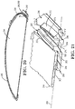
- FIG. 1 is a partially exploded view of a wafer shipper in an embodiment of the disclosure
- FIG. 2A is an assembled perspective view of the wafer shipper of FIG. 1 ;
- FIG. 2B is an assembled top view of the wafer shipper of FIG. 1 ;
- FIG. 2C is an assembled bottom view of the wafer shipper of FIG. 1 ;
- FIG. 2D is an assembled front side view of the wafer shipper of FIG. 1 ;
- FIG. 2E is an assembled right side view of the wafer shipper of FIG. 1 ;
- FIG. 2F is an assembled back side view of the wafer shipper of FIG. 1 ;
- FIG. 2G is an assembled left side view of the wafer shipper of FIG. 1 ;
- FIG. 3 is a lower perspective view of a cover portion of the wafer shipper of FIG. 1 in an embodiment of the disclosure
- FIG. 4 is a sectional view of the assembled wafer shipper of FIG. 2 ;
- FIG. 4A is an enlarged, partial sectional view of the cover portion and the stack of an assembled wafer shipper of FIG. 3 ;
- FIG. 4B is an enlarged, partial sectional view of an alternative cover portion in an embodiment of the disclosure.
- FIG. 5 is an enlarged, partial sectional view of the cover portion, receptacle portion, and stack of the assembled wafer shipper of FIG. 2 ;
- FIG. 6 is a perspective view of a wafer support ring in an embodiment of the disclosure.
- FIG. 7 is an enlarged, partial sectional view of the wafer support ring of FIG. 6 ;
- FIG. 8 is an enlarged, partial sectional view of the wafer support ring of FIG. 6 with a resident wafer in an embodiment of the disclosure
- FIG. 9 is a partial sectional view of a stack of wafer support rings with an example resident wafer in an embodiment of the disclosure.
- FIG. 10 is a perspective view of a wafer support ring defining a plurality of posts in an embodiment of the disclosure
- FIG. 10A is an enlarged view of a post of FIG. 10 ;
- FIGS. 10B through 10D are plan views of alternative post arrangements in embodiments of the disclosure.
- FIG. 11 is a simplified plan view of the wafer support ring of FIG. 10 with the posts enhanced for clarity in an embodiment of the disclosure;
- FIGS. 12A and 12B are enlarged sectional views of the wafer support ring of FIG. 10 ;
- FIG. 13 is a schematic of a wafer shipper depicted as a multiple damper system and utilizing a stack that does not transfer compression forces to the resident wafers in an embodiment of the disclosure;
- FIG. 14 is a schematic of a wafer shipper depicted as a multiple damper system and utilizing a stack that transfers compression forces to the resident wafers in an embodiment of the disclosure;
- FIG. 15 is a schematic of a single wafer shipper in an embodiment of the disclosure.
- FIG. 16 is a partially exploded view of a wafer shipper in an embodiment of the disclosure.
- FIG. 17 is an assembled perspective view of the wafer shipper of FIG. 16 ;
- FIG. 18 is a perspective view of a wafer support ring in an embodiment of the disclosure.
- FIG. 19 is a sectional view of the wafer support ring of FIG. 18 ;
- FIG. 20 is a sectional view of the wafer support ring of FIG. 18 with a resident wafer in an embodiment of the disclosure
- FIG. 21 is an enlarged, partial view of FIG. 20 ;
- FIG. 22 is a partial sectional view of a stack of wafer support rings with an example resident wafer in an embodiment of the disclosure
- FIG. 23 is a sectional view of the wafer support ring of FIG. 18 with a resident wafer having a longer chord length in an embodiment of the disclosure;
- FIG. 24 is an enlarged, partial view of FIG. 23 ;
- FIG. 25 is a partial sectional view of the wafer support ring of FIG. 18 with a resident wafer in an embodiment of the disclosure
- FIG. 26 is an enlarged, partial view of FIG. 25 ;
- FIG. 27 is a perspective view of a receptacle of the shipper of FIGS. 16 and 17 in an embodiment of the disclosure.
- FIG. 28 is a bottom perspective view of the receptacle of FIG. 27 .
- a wafer shipper 30 is depicted in an embodiment of the disclosure.
- the wafer shipper 30 includes a cover portion 32 and a receptacle portion 34 .
- a plurality of wafer support rings 36 are disposed in a stack 38 within the wafer shipper 30 , the stack 38 being substantially concentric about a mounting axis 42 defined by the cover portion 32 of the wafer shipper 30 .
- the wafer support rings 36 are each shaped and dimensioned to support a wafer 44 having an outer periphery 46 ( FIG. 8 ).
- the mounting axis 42 is concentric with a z-axis of a cylindrical (r- ⁇ -z) coordinate system 45 .
- a substantially continuous line or band of contact 48 ( FIG. 5 ) is established between each wafer support ring 36 and the wafer 44 supported thereby.
- the cover portion 32 includes a body 54 having a top portion 50 and a continuous side portion 51 that depends therefrom.
- the top portion 50 can include radially extending ribs 53 that extend from proximate the mounting axis 42 of the cover portion 32 .
- the radially extending ribs 53 are on the interior of the top portion 50 of the cover portion proximate the mounting axis 42 , and transitions to the exterior of the top portion 50 proximate the side portion 51 of the cover portion 32 , each radially extending rib 53 being contiguous through the transition.
- deflectable corner flanges 52 are cantilevered from the body 54 of the cover portion 32 .
- Each corner flange 52 can include structure defining an aperture 56 .
- latching members 58 extend from the receptacle portion 34 substantially parallel to the mounting axis 42 , each being arranged to pass through a respective one of the apertures 56 to interlock with the respective corner flange 52 .
- the cover portion 32 includes a stop portion 59 having an axial face 59 a that extends into wafer shipper to engage with and contact the stack 38 .
- the stop portion can include axially extending protrusions 59 b that depend from the axial face 59 a and occupy an inner radial portion of the axial face 59 a.
- the radial extremity of the axially extending protrusions 59 b define a radius Rp.
- the receptacle portion 34 includes a base 55 .
- a mounting ring 57 extends upwards from the base 55 to engage a lowermost wafer support ring 36 z ( FIG. 5 ).
- the radially extending ribs 53 provide rigidity to the top portion 50 of the cover portion 32 while facilitating flow of material during molding of the cover portion 32 .
- the corner flanges 52 provide spring loading of the cover portion 32 against the top of the stack 38 to secure the stack 38 between the cover portion 32 and the base portion 34 .
- the axially extending protrusions 59 b provide alignment of the stack 38 with respect to the mounting axis 42 , as described below attendant to FIG. 6 .
- a wafer support ring 60 (i.e., one of the plurality of wafer support rings 36 ) is depicted in an embodiment of the disclosure.
- the wafer support ring 60 defines a central axis 62 and includes a flange portion 64 having a first axial face 66 and a second axial face 68 , the second axial face 68 being opposite the first axial face 66 .
- the wafer support ring 60 further includes a ridge portion 70 and an outer rim portion 72 .
- the ridge portion 70 protrudes in an axial direction 74 parallel to the central axis 62 to a distal edge 75 from the first axial face 66 of the flange portion 64 .
- the first axial face 66 of the flange portion 64 includes a planar surface portion 76 that is radially inset from and adjacent to the ridge portion 70 , with the distal edge 75 of the ridge portion 70 extending to a height (axial dimension) 77 ( FIG. 7 ) relative to the planar surface portion 76 and registration plane 78 .
- the central axis 62 is concentric with a z-axis of a cylindrical (r- ⁇ -z) coordinate system 79 .
- the planar surface portion 76 defines a registration plane 78 ( FIGS. 7 and 8 ) for the resident wafer 44 .
- the substantially continuous line or band of contact 48 referred to in discussion of FIG. 5 , is established between the wafer 44 and the planar surface portion 76 ( FIG. 8 ).
- the first axial face 66 of the flange portion 64 can include an inclined portion 82 that extends radially inward from the planar surface portion 76 of the flange portion 64 , the inclined portion 82 extending toward the central axis 62 and away from the registration plane 78 .
- a junction 84 between the ridge portion 70 and the planar surface portion 76 of the flange portion 64 defines a radius Rmax relative to the central axis 62 .
- the radius Rmax can be is dimensioned to provide a close tolerance fit with the outer periphery 46 of the resident wafer 44 .
- the radius Rmax can be said to define a circumference of an inner face 85 ( FIG. 7 ) of the ridge portion 70 , the circumference being equal to 2 ⁇ Rmax.
- the planar surface portion 76 can be dimensioned so as not to encroach on the Fixed Quality Area (FQA) of the resident wafer 44 , as stipulated by ISTA-2A when the resident wafer 44 is registered within the wafer support ring 60 .
- FQA Fixed Quality Area
- the dimension of Rmax is slightly greater than the radius Rp defined by the radial extremities of the axially extending protrusions 59 b.
- the axially extending protrusions 59 b are inserted radially inward from the ridge portion 70 of an uppermost wafer support ring 60 of the stack 38 (identified as an uppermost wafer support ring 36 a in FIG. 4A ), thereby providing alignment of the stack 38 relative to the cover portion 32 upon closure of the wafer shipper 30 .
- an outer portion of the axial face 59 a remains radially outward from the radial extremities of the axially extending protrusions 59 b for seating of the stop portion 59 against the uppermost wafer support ring 36 a.
- the stop 59 defines a step 59 c that transitions to a second axial face 59 d, the second axial face 59 d extending further downward (i.e., further toward the base 55 of the receptacle portion 34 ) than the axial face 59 a.
- the step 59 c can be located at approximately the same radius Rp as the axially extending protrusions 59 b of FIG. 3 , so as to be inserted radially inward from the ridge portion 70 of the uppermost wafer support ring 36 a.
- the step 59 c can provide the same centering function as the axially extending protrusions 59 b of FIGS. 3 and 4A .
- the second axial face 68 of the wafer support ring 60 includes structure defining a groove or channel 90 .
- the channel 90 is bounded by an inner radial wall 91 , an outer radial wall 92 , and a recessed axial face 93 between the inner and outer radial walls 91 and 92 ( FIG. 8 ).
- the flange portion 64 of the support ring 60 can be characterized as defining an axial thickness 95 between the recessed axial face 93 and the registration plane 78 .
- the inner and outer radial walls 91 and 92 respectively define an inner radius Ri and an outer radius Ro relative to the central axis 62 .
- the channel 90 is continuous.
- the ridge portion 70 is occupies an annular band ⁇ R on the first axial face 66 that is defined between the inner radius Ri and the outer radius Ro, such that the ridge portion 70 is disposed over the channel 90 .
- a partial sectional view of the assembled stack 38 containing a pair of resident wafers 44 is depicted in an embodiment of the disclosure.
- a first wafer support ring 60 a is stacked atop a second wafer support ring 60 b so that the distal edge 75 b of the ridge portion 70 b of the second wafer support ring 60 b registers within a channel 90 a of the first wafer support ring 60 a to define a substantially continuous band of contact 94 between the distal edge 75 b and the recessed axial face 93 a of the channel 90 a.
- a gap 96 having an axial dimension 98 is defined between a planar surface portion 76 b of the second wafer support ring 60 b and the second axial face 68 a of the wafer support ring 60 a when the ridge portion 70 b is registered within the channel 90 a.
- a void 99 is defined between the adjacent wafers 44 , the void 99 being bound on the perimeter by successively stacked wafer supporting rings 60 .
- wafers 44 are loaded into each wafer support ring 60 of the plurality of wafer support rings 36 and the wafer support rings 36 positioned atop each other to form the stack 38 .
- the cover portion 32 is then aligned with and coupled to the receptacle portion 34 so that the latching members 58 are interlocked within the corner flanges 52 via the apertures 56 .
- the cover portion 32 is dimensioned so that the stop portion 59 is firmly engaged with the stack 38 upon interlock with the receptacle portion 34 .
- a substantially continuous band of contact 102 is developed between the stop portion 59 and an uppermost wafer support ring 36 a of the plurality of wafer support rings 36 .
- An upper gas pocket 104 is thereby defined in the between the cover portion 32 and the stack 38 , the upper gas pocket 104 being bounded by the cover portion 32 , stop portion 59 , contact band 102 , uppermost wafer support ring 36 a, an adjacent wafer support ring 36 b adjacent to the uppermost wafer support ring 36 a, and the uppermost wafer 44 a.
- a boundary 106 of the upper gas pocket 104 is depicted with increased line weight in FIG. 4A for clarity.
- the uppermost wafer 44 a can be disposed in the uppermost wafer support ring 36 a, as depicted in FIG. 4B .
- a gap 107 is defined between the second axial face 59 d and the registration plane 78 of the uppermost wafer 44 a.
- the gap 107 can be of approximately the same dimension as the gap 96 , thereby performing the same retention and capture functions as the gaps 96 .
- the uppermost wafer 44 a is prevented from “jumping” the ridge portion 70 of the uppermost wafer support 36 a and becoming damaged because of entrapment between the ridge portion 70 and the axial face 59 a of the stop portion 59 .
- FIGS. 3 and 4A can also be configured for housing the uppermost wafer 44 a in the uppermost wafer support ring 36 a (not depicted).
- the axially extending protrusions 59 b can have an axial dimension that provides an axial clearance (not depicted) between their lower extremities and the registration plane 78 , allowing a wafer 44 to be disposed in the uppermost wafer support ring 36 a.
- the axial clearance thus defined can operate similar to the gap 107 of FIG. 4B .
- a “substantially continuous band of contact” is an interface that is uninterrupted in the ⁇ -coordinate of an r- ⁇ -z coordinate (e.g., coordinates 45 and 79 ) and provides contact across the interface except at microscopic level, where surface roughness and slight surface imperfections such as scratches and a shallow waviness may create discontinuities in the contact.
- the contact is not continuous in a microscopic sense, but is “substantially continuous.”
- the height of the stack 38 can vary notably from one stack to another.
- the wafer shipper 30 is configured so that when the cover portion 32 is interlocked with the receptacle portion 34 , the latching members 58 are in axial tension for a range of heights for the stack 38 that are within the accumulated build up uncertainty of the stack 38 , with the flexible corner flanges 52 flexing to take up the build up uncertainty of the stack 38 .
- the interlocking of the cover portion 32 to the receptacle portion 34 assures that the stop portion 59 exerts a compressive force on the stack 38 .
- Such arrangement is discussed in further detail in a U.S.
- the resident wafer 44 is captured within the gap 96 and is limited in axial movement during the rigors of transport (e.g., during an impact episode).
- the close tolerance fit between the junction 84 and the outer periphery 46 of the resident wafer 44 limits lateral movement of the resident wafer(s) 44 during transport.
- the channel 90 a further prevents the wafer 44 from “jumping” the ridge portion 70 b and becoming damaged because of entrapment between the ridge portion 70 b and the second axial face 68 a of the adjacent wafer support ring 60 a.
- the registration of the resident wafer 44 and the planar surface portion 76 further provides a flow restriction between the resident wafer 44 and the wafer support ring 60 b .
- the flow restriction can act as a damper that slows the release of gas from the void 99 , as well as from voids defined between other adjacent wafers and the plurality of wafer support rings 36 .
- the same dynamic applies to the trapped gas bubble or constrained gas pocket of the upper and lower gas pockets 104 and 109 . Due to the effect of the gas within a given void 99 an/or the upper and lower gas pockets 104 and 109 the being slowly released (“slow” relative to the duration of the impact event), there is a damping effect that further cushions the resident wafer(s) 44 from impact damage.
- the uppermost wafer support ring 36 a of the plurality of wafer support rings 36 is unoccupied (i.e., does not contain a wafer).
- the uppermost wafer support ring 36 a serves to capture an uppermost wafer 44 a that is disposed in the adjacent wafer support ring 36 b (i.e., the wafer support ring 36 b upon which the wafer support ring 36 a is mounted).
- the uppermost wafer 44 a residing in the wafer support ring 36 b is prevented from being dislodged from the wafer support ring 36 b during an impact event.
- the gap 96 within which the uppermost wafer 44 a resides is maintained during an impact event, and the cushioning effect described above is also maintained and operative.
- a wafer support ring 110 is depicted in an embodiment of the disclosure.
- the wafer support ring 110 includes many of the same components and features as the wafer support ring 60 , which are indicated with same-numbered numerical references.
- the wafer support ring includes a ridge portion 112 that protrudes in the axial direction 74 parallel to the central axis 62 from the first axial face 66 of the flange portion 64 .
- the ridge portion 112 defines a first radial thickness 114 and a second radial thickness 116 , the second radial thickness 116 being greater than the first radial thickness.
- one or more transitions 118 are defined between the first and second radial thicknesses 114 and 116 .
- the portions of the ridge portion 112 that include the second radial thickness 116 and any adjacent transition(s) 118 are indicated at FIG. 11 as posts 120 a through 120 h, which are referred to herein generically or collectively as post(s) 120 .
- the ridge portion 112 is divided into eight ridge sections 122 a through 122 h, referred to generically and collectively as ridge section(s) 122 .
- Each ridge section 122 has a respective arc length, depicted at FIG. 11 as arc lengths 123 a through 123 h, and which are referred to herein generically or collectively as arc length(s) 123 .
- the arc lengths 123 can be characterized in either units of length (e.g., centimeters) or angle (e.g., degrees).
- Each ridge section 122 includes a first arc segment 124 , defined as the portion of the ridge section 122 having the first radial thickness 114 between two neighboring posts 120 , and a second arc segment 126 , defined as the portion of the ridge section 122 having the second radial thickness 116 and any transition(s) 118 adjacent thereto (i.e., a given post 120 ).
- the first and second arc segments 124 and 126 are depicted only for ridge section 122 c in FIG.
- the second arc segments 126 are uniformly distributed angularly about the central axis 62 , such that each ridge section 122 subtends the same angle ⁇ .
- a ratio of the second radial thickness 116 to the first radial thickness 114 is within a range 1.4 to 1.8 inclusive; in other embodiments, the ratio is within a range of 1.3 to 2 inclusive; in still other embodiments, the ratio is within a range of 1.2 to 3 inclusive. (Herein, a range that is said to be “inclusive” includes the endpoint values stated for the range.) In various embodiments, a majority of the circumference of the ridge portion 112 is of the first radial thickness 114 .
- the first arc segment 124 of a given ridge section 122 is from 75% to 85%(inclusive) of the arc length 123 of the ridge section 122 ; in other embodiments, from 75% to 95% inclusive; in other embodiments, from 70% to 95% inclusive.
- the number of posts 120 is between 3 and 12 inclusive; in some embodiments, between 4 and 10 posts 120 inclusive; in some embodiments, between 6 and 8 posts 120 inclusive.
- the posts 120 can be, but need not be, equally distributed about the central axis 62 as depicted.
- the thinner first radial thicknesses 114 reduces the influence of shrinkage of the first arc segments 124 that is inevitable with certain injection molded materials, thereby preventing warpage of the support ring 110 . That is, for ridge sections 122 that incorporate a sufficiently thick radial thickness relative to the axial thickness 95 , the effect of shrinkage exerts a radial force on the top of the flange portion 64 that is sufficient to cause the flange portion to bow perceptibly (i.e., to cause the support ring 110 to fall outside specified flatness and waviness tolerances). For ridge sections 122 where the radial thickness is sufficiently thin, the force exerted by the shrinkage can be diminished, so that specified manufacturing tolerances are maintained.
- warpage is sufficiently abated where a ratio of the first radial thickness 114 to the axial thickness 95 is in the range of 0.1 to 1.5 inclusive. In some embodiments, the ratio of the first radial thickness 114 to the axial thickness 95 is in the range of 0.5 to 1.2 inclusive; in some embodiments, 0.8 to 1.1 inclusive.
- the posts 120 provide load-bearing capability for stacking the wafer support rings 110 without buckling or fracturing, for example in an impact event.
- the posts 120 while presenting a thicker radial thickness, constitute a small enough portion of the support ring 110 so as not to cause significant warpage of the support ring 110 during cooling.
- the height 77 is uniform around the circumference of the ridge portion 112 , thereby retaining certain favorable operating characteristics when stacked with other support rings, as described below.
- the posts 120 can be of various footprint shapes, including the alternate shapes.
- the second radial thickness 116 in combination with the transitions 118 define posts 120 having a polygonal shape ( FIG. 10A ).
- the footprint shapes for the posts 120 include a triangular profile ( FIG. 10B ), a semi-circular profile ( FIG. 10C ), and a rectangular profile ( FIG. 10D ).
- a wafer shipper 130 is schematically depicted in an embodiment of the disclosure.
- the wafer shipper 130 is a simplified version of the wafer shipper 30 to facilitate a discussion of the dampening dynamics of the wafer shipper 30 , and thus has many of the same components and attributes of the wafer shipper 30 , which are indicated with same-numbered numerical references.
- the wafer shipper 130 schematically depicts the voids 99 , the upper gas pocket 104 , and the lower gas pocket 109 as dampening chambers that are analogously represented as dashpots that are serially connected.
- Dashpots 132 represent the dampening provided by the voids 99 ; a dashpot 132 a represents the dampening provided by the upper gas pocket 104 ; and a dashpot 132 z represents the dampening provided by the lower gas pocket 109 .
- the wafer shipper 130 is deflected, causing the gas within to be suddenly and momentarily compressed. Because the voids 99 , upper gas pocket 104 , and lower gas pocket 109 are analogous to a series of dashpots 132 , 132 a, and 132 z, the effect of the compression is spread out over all of the wafers 44 .
- a compression that originates by an inward deflection of the top of the cover 32 This acts to compress the gas in the upper pocket 104 , which in turn deflects the uppermost wafer 44 a downward.
- the downward deflection of wafer 44 a is resisted by compression of the void 99 a that is adjacent to wafer 44 a, thus keeping the magnitude of the deflection of the uppermost wafer 44 a in check.
- the compression of the void 99 a causes an adjacent wafer 44 b to deflect downward, which is resisted by compression of the void 99 b, and so on.
- the deflection/compression sequence rapidly progresses through the stack 38 .
- the substantially continuous bands of contact 48 , 94 , 102 , and 108 a network of slow leaking gas enclosures is established between the voids 99 and the enclosed upper and lower gas pockets 104 and 109 which acts to distribute the compression caused by the impact load. That is, the substantially continuous bands of contact 48 , 94 , 102 , and 108 create flow restrictions therethrough when the voids 99 and the enclosed upper and lower gas pockets 104 and 109 become suddenly pressurized, for example during a compression experienced during an impact event.
- the wafers 44 may lift away from the planar surface 76 of the flange portion 64 during an impact event, particularly for thinner wafers 44 that leave substantial clearance between the wafer 44 and the gap 96 within which the wafer 44 resides, such that the otherwise substantially continuous line or band of contact 48 is no longer continuous. While the lifting away may somewhat vitiate the restriction to flow, the lifting of the wafer 44 is limited by the clearance between the wafer 44 and the gap 96 , so that any such opening may be limited to a small dimension. The small dimension of the lifting away can still effectively restrict the flow to create a slow release of gas relative to the duration of an impact episode.
- the compression load would not be distributed as described above.
- the uppermost wafer 44 a could deflect upward in an unchecked manner during an impact event, which could cause damage to the uppermost wafer 44 a.
- an impact event that would cause the lowermost wafer 44 z to deflect downward could cause damage if the lower pocket there were no flow restriction provided by the substantially continuous band of contact 108 to provide the dampening effect.
- the dampening effect is particularly beneficial in for larger diameter wafers (for example, but not limited to, 300 mm and 450 mm wafers), where the spans of the wafer between support points can be quite large, leading to substantial deflection of a given wafer.
- the dampening can also help prevent adjacent wafers from colliding with each other during deflection. That is, because the analogous dashpots 132 are in series, the wafers tend to deflect substantially in the same direction, mitigating the chances of any two wafers colliding at their respective maximum deflection points.
- This aspect of the dampening mechanism can enable smaller separation between the resident wafer for a more densely packed stack.
- the dampening effect not only reduces the deflection of the resident wafers 44 ; the dampening effect also reduces the degree to which thinner wafers 44 are lifted off its respective wafer support ring 36 .
- “Thinner wafers” are wafers that do not substantially fill the gap 96 between adjacent wafer support rings 36 (e.g., wafer support rings 60 a and 60 b of FIG. 9 ). Accordingly, the wafers can be displaced or “rattle” within the gap 96 during impact events or periods of high vibration, which can damage the wafer 44 proximate the outer periphery 46 .
- the dampening effect of the voids 99 and gas pockets 104 and 109 can act to reduce or retard (slow down) the displacement, which in turn can prevent damage to the resident wafer 44 .
- the stack 38 transfers the compressive load exerted by the stop portion 59 through the plurality of wafer support rings 36 without exerting force on the resident wafers 44 .
- impact loads any impact load that is transferred through the stack 38 is not transferred through any of the resident wafers 44 .
- a wafer shipper 134 is schematically depicted in an embodiment of the disclosure.
- the wafer shipper 134 includes many of the same components and attributes as the wafer shipper 134 of the FIG. 13 schematic, which are identified by same-numbered numerical references.
- the wafer supports 36 are in contact with both wafers 44 that are adjacent thereto to define a stack 138 that transfers compressive forces through the resident wafers 44 .
- the stack 138 is not supported on a mounting ring (i.e., there is no proud structure akin to mounting ring 57 that extends upward from the base 55 ); rather, the lowermost support ring 36 z is seated on a flat portion of the base 55 , forming the substantially continuous band of contact 108 therebetween.
- the general principle of limiting wafer deflection due to the dampening provided by the gas within the voids 99 and gas pockets 104 , 109 is the same as described attendant to the wafer shipper 130 of FIG. 13 .
- the wafer shipper 134 includes some of the same components and attributes as the wafer shipper 134 of the FIG. 13 schematic, which are identified by same-numbered numerical references.
- the wafer shipper 150 is the same as wafer shipper 130 sans the wafer support rings 36 and stack 38 .
- the upper gas pocket 104 and the lower gas pocket 109 operate to counter deflection of the resident wafer, similar to the voids 99 and gas pockets 104 , 109 of the wafer shipper 130 schematically depicted in FIG. 13 .
- a wafer shipper 230 is depicted in an embodiment of the disclosure.
- the wafer shipper 230 includes a cover portion 232 and a receptacle portion 234 .
- a plurality of wafer support rings 236 are disposed in a stack 238 within the wafer shipper 230 , the stack 238 being substantially concentric about a mounting axis 242 of the receptacle portion 234 .
- Each wafer support ring 236 is shaped and dimensioned to support a wafer 244 having an outer periphery 246 and a primary wafer flat 248 , the primary wafer flat 248 that defining a chord 252 ( FIG. 20 ).
- a wafer support ring 260 of the plurality of wafer support rings 236 is depicted in an embodiment of the disclosure.
- the wafer support ring 260 defines a central axis 262 and includes a flange portion 264 having a first face 266 and a second face 268 , the second face 268 being opposite the first face 266 .
- the wafer support ring 260 further comprises an outer rim portion 272 that protrudes in an axial direction 274 parallel to the central axis 262 from the first face 266 of the flange portion 264 to a distal extremity 275 .
- the first face 266 of the flange portion 264 includes a planar surface portion 276 that is radially inset from and adjacent to the outer rim portion 272 .
- the wafer support ring 260 further includes a wafer flat support structure 280 that extends radially inward from the flange portion 264 .
- the wafer flat support structure 280 includes a first surface 281 having a planar surface portion 282 that is radially inset from the planar surface portion 276 of the flange portion 264 , the planar surface portion 282 of the wafer flat support structure 280 defining a linear edge 284 .
- the linear edge 284 defines a minimum radius Rmin from the central axis 262 of the planar surface portion 282 of the wafer flat support structure 280 , the linear edge 284 extending substantially orthogonal to the central axis 262 and substantially perpendicular to the minimum radius Rmin.
- the wafer support ring 260 further includes a first tab portion 286 that extends radially outward from the outer rim portion 272 and along a first tangential length 288 of the rim portion 272 .
- the planar surface portions 276 and 282 define a registration plane 290 for the resident wafer 44 . Registration of the wafer 244 against planar surface portions 276 and 282 can provide a substantially continuous band of contact between the wafer 244 and the wafer support ring 260 , with beneficial effects as discussed above in relation to the substantially continuous band of contact 48 discussed above.
- the cover portion 232 can be configured to mate with an uppermost support ring of the stack 238 , and the receptacle portion 234 configured to mate with a lowermost support ring of the stack 238 , to define a gas pockets akin to gas pockets 104 and 109 of FIG. 13 , again with attendant benefits as described above.
- the wafer flat support structure 280 includes a rib 292 that protrudes in an axial direction 294 parallel to the central axis 262 , the rib 292 being radially inset from the outer rim portion 272 and radially outset from the planar surface portion 282 of the wafer flat support structure 280 .
- the rib 292 protrudes from the first face 281 of the wafer flat support structure 280 and in the same axial direction 274 as the outer rim portion 272 .
- the rib 292 includes a linear portion 296 that extends parallel to the linear edge 284 of the planar surface portion 282 of the wafer flat support structure 280 .
- the first face 281 of the wafer flat support structure 280 includes an inclined portion 302 that extends radially inward from the linear edge 284 of the planar surface portion 282 of the wafer flat support structure 280 , the inclined portion 302 extending toward the central axis 262 and away from the registration plane 290 .
- the first face 266 of the flange portion 264 can include an inclined portion 304 that extends radially inward from the planar surface portion 276 of the flange portion 264 , the inclined portion 304 extending toward the central axis 262 and away from the registration plane 290 .
- a junction 306 between the outer rim portion 272 and the planar surface portion 276 of the flange portion 264 defines a radius Rmax relative to the central axis 262 that provides a close tolerance fit with the outer periphery 46 of the resident wafer 44 .
- a junction 308 between the linear portion 296 of the rib 292 and the planar surface portion 282 of the wafer flat support structure 280 can provide a close tolerance fit with the primary wafer flat 48 of the resident wafer 44 .
- planar surface portions 276 and 282 can be dimensioned so as not to encroach on the Fixed Quality Area (FQA) of the resident wafer 44 , as stipulated by ISTA-2A when the resident wafer 44 is registered within the wafer support ring 260 .
- FQA Fixed Quality Area
- each wafer support ring 260 of the plurality of wafer support rings 236 includes structure defining a first circular groove 312 , within which the outer rim portion 272 of an adjacent one of the plurality of wafer support rings 236 is seated.
- the second face 268 also includes structure defining a second groove 314 , the second groove 314 being dimensioned and shaped to register the rib of the adjacent of the plurality of wafer support rings 236 .
- the stack 238 captures the resident wafer(s) 44 and limits axial movement thereof during an impact episode.
- the close tolerance fits between the junction 306 and the outer periphery 46 and between the junction 308 and the linear portion 296 of the rib 292 limits lateral movement of the resident wafer 44 during an impact episode.
- the grooves 312 and 314 further prevent the wafer from “jumping” the outer rim portions 272 and the ribs 292 , respectively, and becoming damaged because of entrapment between the outer rim portion 272 and/or the rib 292 and the second face 268 of the adjacent one of the plurality of wafer support rings 236 .
- the registration of the resident wafer 44 and the planar surface portions 276 and 282 further provides a flow restriction between the resident wafer 44 and the wafer support ring 260 .
- the flow restriction can act as a damper between adjacent “pockets” defined between the plurality of wafer support rings 236 and the resident wafer(s) 44 , due to the effect of the air captured and slowly released from the pocket. The damping effect further cushions the resident wafer(s) 44 from impact damage.
- a resident wafer 322 having a longer chord 324 than the chord 252 of the resident wafer 44 is depicted in the wafer support ring 260 in an embodiment of the disclosure.
- standard 150 mm wafers can have primary flats 48 with chords 252 of 47.5 mm and 57.5 mm.
- the longer length of the chord 324 reduces a minimum radius Rmin' between the central axis 262 and the chord 252 .
- the wafer support ring 260 can be modified by disposing the rib 292 closer to the central axis 262 . In other embodiments, such as depicted in FIGS.
- the primary flat is left suspended over the inclined portion 302 of the wafer flat support structure 280 .
- an axial gap 326 is defined between the primary flat 48 and the inclined portion 302 that is on the order of 0.05 mm when the resident wafer 322 is registered within the wafer support ring 260 .
- the relatively small dimension of the gap 326 still limits axial deflection of the primary flat 48 during an impact episode.
- the relatively small dimension of the gap 326 can still provide some restriction of flow, thereby facilitating the cushioning effect of the “pockets” between the resident wafers 322 .
- certain wafer types can include a secondary wafer flat 332 ( FIG. 23 ).
- the secondary wafer flat 332 is typically an identification feature, wherein the position relative to the primary flat 48 depends on some characteristic of the resident wafer 44 , 322 .
- the secondary flat 332 can be of 37.5 mm length and can be centered at angles of 45° , 90° , 135° , and 180° from the center of the primary flat 48 .
- Some wafers have no secondary flat at all. Accordingly, the secondary flat 332 can appear in many different positions relative to the primary flat 48 .
- FIGS. 25 and 26 an example and non-limiting embodiment depicting the secondary flat 332 as located within the wafer support ring 260 is depicted.
- a maximum gap 334 over the inclined portion 304 of the flange portion 264 is on the order of 0.1 mm.
- the relatively small dimension of the maximum gap 334 still limits axial deflection of the primary flat 48 during an impact episode.
- the relatively small dimension of the maximum gap 334 can also still provide some restriction of flow, thereby facilitating the cushioning effect of the “pockets” between the resident wafers 322 .
- the wafer support ring 260 can also include a second tab portion 362 extending radially outward from and along a second tangential length 364 of the rim portion 272 , the second tangential length 364 being of a different dimension than the first tangential length 288 of the first tab portion 286 .
- the first tab portion 286 can be diametrically opposed to the second tab portion 362 .
- the wafer support ring 260 can also include a third tab portion 366 extending radially outward from and along a third tangential length 368 of the rim portion 272 .
- the third tangential length can be of a different dimension than the first tangential length 288 and the second tangential length 364 .
- the first tab portion 286 , the second tab portion 362 , and the third tab portion 366 are asymmetrically disposed about the central axis 262 .
- the wafer support ring 260 includes a fourth tab portion 372 extending radially outward from and along a fourth tangential length 374 of the rim portion 272 , the fourth tab portion 372 being diametrically opposed to the third tab portion 366 about the central axis 262 .
- the third tab portion 366 and the fourth tab portion 372 each define a first plan view profile 370 of substantially same shape and substantially same dimensions (e.g., substantially the shape of a semi-circle, as depicted in FIG. 18 ).
- the wafer support ring 260 includes a fifth tab portion 376 extending radially outward from and along a fifth tangential length 378 of the rim portion 272 .
- the wafer support ring 260 includes a sixth tab portion 382 extending radially outward from and along a sixth tangential length 384 of the rim portion 272 , sixth tab portion 382 being diametrically opposed to the fifth tab portion 376 about the central axis 262 .
- the fifth tab portion 376 and the sixth tab portion 382 each define a second plan view profile 380 of substantially same shape and substantially same dimensions, the second plan view profile 380 being at least one of different shape and different dimensions than the first plan view profile 370 .
- the third tab portion 366 , the fourth tab portion 372 , the fifth tab portion 376 , and the sixth tab portion 382 each include a flat surface 386 for engagement with a vacuum pad (not depicted). Also, in the depicted embodiments, the flat surfaces 386 extend radially inward through the outer rim portion 272 , thereby providing more area for engagement of the vacuum pad.
- the outer rim portion 272 is depicted as being discontinuous at the various tab portions 286 , 362 , 366 , 372 , 376 , and 382 because of the flat surfaces 386 extending through the outer rim portion 272 .
- the distal edge 275 of the outer rim portion is continuous and defines a plane (not depicted), so that, when the wafer support rings 236 are stacked as depicted in FIG. 22 , a substantially continuous line or band of contact is defined between adjacent wafer support rings, akin to the substantially continuous band of contact 94 between wafer support rings 36 of FIG. 5 , with benefits as described herein.
- the receptacle portion 234 of the wafer shipper 230 is depicted in an embodiment of the disclosure.
- the receptacle portion 234 includes a base portion 202 and at least one arcuate wall portion 404 extending from the base portion, the at least one arcuate wall 404 portion being centered about and substantially parallel to the mounting axis 42 , the at least one arcuate wall portion 404 defining a first lateral opening 406 dimensioned to receive the first tab portion 286 of the wafer support ring 260 .
- the at least one arcuate wall portion 404 can define a first lateral recess (not depicted) to receive the first tab portion 286 .
- the at least one arcuate wall portion 404 comprises a pair of opposed arcuate wall portions 404 a and 404 b, the opposed arcuate wall portions 404 a and 404 b being centered about the mounting axis 42 , the pair of opposed arcuate wall portions 404 a and 404 b defining the first lateral opening 406 and a second lateral opening 408 therebetween.
- the second lateral opening 408 is dimensioned to accept the second tab portion 162 .
- the at least one arcuate wall portion 404 can define a second lateral recess (not depicted) to receive the second tab portion 286 .
- the at least one arcuate wall portion 404 can also include lateral recesses 410 that are located and dimensioned to receive the various tab portions of the wafer support ring.
- the at least one arcuate wall portion 404 can define lateral openings instead of lateral recesses located and dimensioned to accommodate the various tab portions of the wafer support ring 260 .
- the various tab portions rotationally fix the wafer support ring 260 within the receptacle 234 and can be arranged to assure that the wafer support ring 260 is not installed upside down in the receptacle 234 .
- the base portion 402 includes a plurality of bosses 412 that are disposed on an underside 414 of the base portion 402 .
- the bosses 412 can be asymmetric with respect to their radial location from the mounting axis 42 , their angular distribution about the mounting axis 42 , and/or their size relative to each other.
- the position of the bosses can be sensed external equipment, for example by limit switches or other proximity switches, to confirm proper orientation of the shipper 230 .
Abstract
Description
Claims (13)
Priority Applications (1)
| Application Number | Priority Date | Filing Date | Title |
|---|---|---|---|
| US15/120,973 US10896834B2 (en) | 2014-02-25 | 2015-02-24 | Wafer shipper with stacked support rings |
Applications Claiming Priority (5)
| Application Number | Priority Date | Filing Date | Title |
|---|---|---|---|
| US201461944455P | 2014-02-25 | 2014-02-25 | |
| US201462089087P | 2014-12-08 | 2014-12-08 | |
| US201462089103P | 2014-12-08 | 2014-12-08 | |
| US15/120,973 US10896834B2 (en) | 2014-02-25 | 2015-02-24 | Wafer shipper with stacked support rings |
| PCT/US2015/017345 WO2015130690A1 (en) | 2014-02-25 | 2015-02-24 | Wafer shipper with stacked support rings |
Publications (2)
| Publication Number | Publication Date |
|---|---|
| US20160365265A1 US20160365265A1 (en) | 2016-12-15 |
| US10896834B2 true US10896834B2 (en) | 2021-01-19 |
Family
ID=54009550
Family Applications (1)
| Application Number | Title | Priority Date | Filing Date |
|---|---|---|---|
| US15/120,973 Active 2036-01-17 US10896834B2 (en) | 2014-02-25 | 2015-02-24 | Wafer shipper with stacked support rings |
Country Status (8)
| Country | Link |
|---|---|
| US (1) | US10896834B2 (en) |
| EP (1) | EP3111472B1 (en) |
| JP (1) | JP2017508291A (en) |
| KR (1) | KR20160126020A (en) |
| CN (1) | CN106463437B (en) |
| SG (1) | SG11201607061WA (en) |
| TW (1) | TWI733648B (en) |
| WO (1) | WO2015130690A1 (en) |
Cited By (1)
| Publication number | Priority date | Publication date | Assignee | Title |
|---|---|---|---|---|
| US20220005718A1 (en) * | 2021-09-21 | 2022-01-06 | Intel Corporation | Contactless wafer separator |
Families Citing this family (16)
| Publication number | Priority date | Publication date | Assignee | Title |
|---|---|---|---|---|
| US10896834B2 (en) | 2014-02-25 | 2021-01-19 | Entegris, Inc. | Wafer shipper with stacked support rings |
| TWI646030B (en) * | 2014-11-27 | 2019-01-01 | 日商阿基里斯股份有限公司 | Ring spacer |
| USD799825S1 (en) * | 2015-08-31 | 2017-10-17 | Entegris, Inc. | Container |
| USD801046S1 (en) * | 2015-08-31 | 2017-10-31 | Entegris, Inc. | Container |
| US10832927B2 (en) * | 2015-12-18 | 2020-11-10 | Texas Instruments Incorporated | Interlocking nest wafer protector |
| DE102016113924A1 (en) | 2016-07-28 | 2018-02-01 | Infineon Technologies Ag | Wafer box, method of arranging wafers in a wafer box, wafer protection plate, and method of protecting a wafer |
| KR101919601B1 (en) | 2016-09-30 | 2019-02-08 | 주식회사 녹십초 알로에 | Electic toothbrush |
| USD812907S1 (en) * | 2017-01-16 | 2018-03-20 | Endural, Llc | Container |
| WO2019046477A1 (en) * | 2017-08-29 | 2019-03-07 | Daewon Semiconductor Packaging Industrial Company | Separators for handling, transporting, or storing semiconductor wafers |
| DE202019101793U1 (en) * | 2018-06-27 | 2019-10-09 | Murata Machinery, Ltd. | Devices for at least one of substrate handling, substrate storage, substrate treatment, and substrate processing |
| JP6934573B2 (en) | 2018-08-01 | 2021-09-15 | 平田機工株式会社 | Transport device and control method |
| US10811292B2 (en) * | 2018-09-12 | 2020-10-20 | Texas Instruments Incorporated | Transport packaging and method for expanded wafers |
| US20200373190A1 (en) * | 2019-05-20 | 2020-11-26 | Applied Materials, Inc. | Process kit enclosure system |
| USD917825S1 (en) | 2019-07-16 | 2021-04-27 | Entegris, Inc. | Wafer support ring |
| JP7330081B2 (en) * | 2019-12-03 | 2023-08-21 | 三菱電機株式会社 | Carrier spacer and semiconductor device manufacturing method |
| WO2023188147A1 (en) * | 2022-03-30 | 2023-10-05 | アキレス株式会社 | Semiconductor wafer transfer container |
Citations (26)
| Publication number | Priority date | Publication date | Assignee | Title |
|---|---|---|---|---|
| JPS61291336A (en) | 1985-06-20 | 1986-12-22 | Matsushita Electric Ind Co Ltd | Delivery device for platelike body |
| JPH0872974A (en) | 1994-09-07 | 1996-03-19 | Shinon Denki Sangyo Kk | Tray for semiconductor device |
| JPH1050815A (en) | 1996-07-31 | 1998-02-20 | Nec Corp | Wafer container |
| US6286684B1 (en) | 1999-07-23 | 2001-09-11 | Ray G. Brooks | Protective system for integrated circuit (IC) wafers retained within containers designed for storage and shipment |
| US6550619B2 (en) | 2000-05-09 | 2003-04-22 | Entergris, Inc. | Shock resistant variable load tolerant wafer shipper |
| JP2004207260A (en) | 2002-11-08 | 2004-07-22 | Vantec Co Ltd | Semiconductor wafer transfer container |
| JP2004241705A (en) | 2003-02-07 | 2004-08-26 | Daifuku Co Ltd | Supported body lamination support device |
| JP2005191419A (en) | 2003-12-26 | 2005-07-14 | Achilles Corp | Housing of semiconductor wafer |
| US7040487B2 (en) | 2001-07-14 | 2006-05-09 | Entegris, Inc. | Protective shipper |
| US20060144752A1 (en) * | 2004-12-30 | 2006-07-06 | Illinois Tool Works Inc. | Adjustable height wafer box |
| US7138726B2 (en) | 2003-02-05 | 2006-11-21 | Texas Instruments Incorporated | Protective interleaf for stacked wafer shipping |
| JP3130509U (en) | 2007-01-16 | 2007-03-29 | 山汰科技企業有限公司 | Substrate transfer device |
| WO2007092557A2 (en) | 2006-02-08 | 2007-08-16 | Entegris, Inc. | Stacking rings for wafers |
| US20070284282A1 (en) | 2006-06-07 | 2007-12-13 | Toshitsugu Yajima | Wafer storage container |
| JP2008044636A (en) | 2006-08-11 | 2008-02-28 | Sanyu Kikaku:Kk | Storage tray |
| JP2009076646A (en) | 2007-09-20 | 2009-04-09 | Shin Etsu Polymer Co Ltd | Substrate holding tool |
| JP2009105116A (en) | 2007-10-22 | 2009-05-14 | Shin Etsu Polymer Co Ltd | Wafer storage container and handling method for wafer |
| US20090127152A1 (en) * | 2006-05-23 | 2009-05-21 | Mohammed Bou-Mezrag | Modular Container for Holding Ventilation-Sensitive Commodities |
| US20090250374A1 (en) | 2007-03-05 | 2009-10-08 | Miraial Co., Ltd. | Semiconductor wafer container |
| US20100224517A1 (en) | 2009-03-03 | 2010-09-09 | Haggard Clifton C | Disk separator device |
| CN101888957A (en) | 2007-10-12 | 2010-11-17 | 必佳塑胶金属制品厂(国际)有限公司 | The wafer container that has staggered wall structure |
| JP2012251214A (en) | 2011-06-03 | 2012-12-20 | Renesas Electronics Corp | Method for manufacturing semiconductor device |
| US20140076774A1 (en) * | 2012-09-18 | 2014-03-20 | Kurt F. Kaashoek | Automated Wafer Container with Equipment Interface |
| WO2015130690A1 (en) | 2014-02-25 | 2015-09-03 | Entegris, Inc. | Wafer shipper with stacked support rings |
| US9224627B2 (en) * | 2011-02-16 | 2015-12-29 | Texchem Advanced Products Incorporated Sdn Bhd | Single and dual stage wafer cushion and wafer separator |
| WO2016094398A1 (en) | 2014-12-08 | 2016-06-16 | Entegris, Inc. | Horizontal substrate container with integral corner spring for substrate containment |
Family Cites Families (1)
| Publication number | Priority date | Publication date | Assignee | Title |
|---|---|---|---|---|
| JP3054701U (en) * | 1998-06-05 | 1998-12-18 | 株式会社倉元製作所 | Glass substrate spacer with film |
-
2015
- 2015-02-24 US US15/120,973 patent/US10896834B2/en active Active
- 2015-02-24 JP JP2016553865A patent/JP2017508291A/en active Pending
- 2015-02-24 SG SG11201607061WA patent/SG11201607061WA/en unknown
- 2015-02-24 EP EP15754712.6A patent/EP3111472B1/en active Active
- 2015-02-24 CN CN201580019500.2A patent/CN106463437B/en active Active
- 2015-02-24 KR KR1020167026139A patent/KR20160126020A/en not_active Application Discontinuation
- 2015-02-24 WO PCT/US2015/017345 patent/WO2015130690A1/en active Application Filing
- 2015-02-25 TW TW104106010A patent/TWI733648B/en active
Patent Citations (27)
| Publication number | Priority date | Publication date | Assignee | Title |
|---|---|---|---|---|
| JPS61291336A (en) | 1985-06-20 | 1986-12-22 | Matsushita Electric Ind Co Ltd | Delivery device for platelike body |
| JPH0872974A (en) | 1994-09-07 | 1996-03-19 | Shinon Denki Sangyo Kk | Tray for semiconductor device |
| US5551572A (en) | 1994-09-07 | 1996-09-03 | Shinon Denkisangyo Kabushiki-Kaisha | Tray for semiconductor devices |
| JPH1050815A (en) | 1996-07-31 | 1998-02-20 | Nec Corp | Wafer container |
| US6286684B1 (en) | 1999-07-23 | 2001-09-11 | Ray G. Brooks | Protective system for integrated circuit (IC) wafers retained within containers designed for storage and shipment |
| US6550619B2 (en) | 2000-05-09 | 2003-04-22 | Entergris, Inc. | Shock resistant variable load tolerant wafer shipper |
| US7040487B2 (en) | 2001-07-14 | 2006-05-09 | Entegris, Inc. | Protective shipper |
| JP2004207260A (en) | 2002-11-08 | 2004-07-22 | Vantec Co Ltd | Semiconductor wafer transfer container |
| US7138726B2 (en) | 2003-02-05 | 2006-11-21 | Texas Instruments Incorporated | Protective interleaf for stacked wafer shipping |
| JP2004241705A (en) | 2003-02-07 | 2004-08-26 | Daifuku Co Ltd | Supported body lamination support device |
| JP2005191419A (en) | 2003-12-26 | 2005-07-14 | Achilles Corp | Housing of semiconductor wafer |
| US20060144752A1 (en) * | 2004-12-30 | 2006-07-06 | Illinois Tool Works Inc. | Adjustable height wafer box |
| WO2007092557A2 (en) | 2006-02-08 | 2007-08-16 | Entegris, Inc. | Stacking rings for wafers |
| US20090127152A1 (en) * | 2006-05-23 | 2009-05-21 | Mohammed Bou-Mezrag | Modular Container for Holding Ventilation-Sensitive Commodities |
| US20070284282A1 (en) | 2006-06-07 | 2007-12-13 | Toshitsugu Yajima | Wafer storage container |
| JP2008044636A (en) | 2006-08-11 | 2008-02-28 | Sanyu Kikaku:Kk | Storage tray |
| JP3130509U (en) | 2007-01-16 | 2007-03-29 | 山汰科技企業有限公司 | Substrate transfer device |
| US20090250374A1 (en) | 2007-03-05 | 2009-10-08 | Miraial Co., Ltd. | Semiconductor wafer container |
| JP2009076646A (en) | 2007-09-20 | 2009-04-09 | Shin Etsu Polymer Co Ltd | Substrate holding tool |
| CN101888957A (en) | 2007-10-12 | 2010-11-17 | 必佳塑胶金属制品厂(国际)有限公司 | The wafer container that has staggered wall structure |
| JP2009105116A (en) | 2007-10-22 | 2009-05-14 | Shin Etsu Polymer Co Ltd | Wafer storage container and handling method for wafer |
| US20100224517A1 (en) | 2009-03-03 | 2010-09-09 | Haggard Clifton C | Disk separator device |
| US9224627B2 (en) * | 2011-02-16 | 2015-12-29 | Texchem Advanced Products Incorporated Sdn Bhd | Single and dual stage wafer cushion and wafer separator |
| JP2012251214A (en) | 2011-06-03 | 2012-12-20 | Renesas Electronics Corp | Method for manufacturing semiconductor device |
| US20140076774A1 (en) * | 2012-09-18 | 2014-03-20 | Kurt F. Kaashoek | Automated Wafer Container with Equipment Interface |
| WO2015130690A1 (en) | 2014-02-25 | 2015-09-03 | Entegris, Inc. | Wafer shipper with stacked support rings |
| WO2016094398A1 (en) | 2014-12-08 | 2016-06-16 | Entegris, Inc. | Horizontal substrate container with integral corner spring for substrate containment |
Cited By (2)
| Publication number | Priority date | Publication date | Assignee | Title |
|---|---|---|---|---|
| US20220005718A1 (en) * | 2021-09-21 | 2022-01-06 | Intel Corporation | Contactless wafer separator |
| US11664257B2 (en) * | 2021-09-21 | 2023-05-30 | Intel Corporation | Contactless wafer separator |
Also Published As
| Publication number | Publication date |
|---|---|
| US20160365265A1 (en) | 2016-12-15 |
| SG11201607061WA (en) | 2016-09-29 |
| EP3111472A1 (en) | 2017-01-04 |
| KR20160126020A (en) | 2016-11-01 |
| TW201539641A (en) | 2015-10-16 |
| CN106463437A (en) | 2017-02-22 |
| CN106463437B (en) | 2019-09-06 |
| EP3111472A4 (en) | 2017-07-12 |
| TWI733648B (en) | 2021-07-21 |
| WO2015130690A1 (en) | 2015-09-03 |
| EP3111472B1 (en) | 2018-09-26 |
| JP2017508291A (en) | 2017-03-23 |
Similar Documents
| Publication | Publication Date | Title |
|---|---|---|
| US10896834B2 (en) | Wafer shipper with stacked support rings | |
| US6550619B2 (en) | Shock resistant variable load tolerant wafer shipper | |
| US7040487B2 (en) | Protective shipper | |
| JP6427674B2 (en) | Horizontal substrate container with integrated corner spring for substrate storage | |
| JP5727495B2 (en) | Wafer container with concave latch | |
| US8393471B2 (en) | Packing insert for disc-shaped objects | |
| WO2007092557A2 (en) | Stacking rings for wafers | |
| US20100224517A1 (en) | Disk separator device | |
| CN103460370A (en) | Single and dual stage wafer cushion | |
| US20040048028A1 (en) | Plastic packaging cushion | |
| JP4329536B2 (en) | Semiconductor wafer storage | |
| WO2017069205A1 (en) | Separator | |
| US20190019704A1 (en) | Glass substrate shipper | |
| US20060105498A1 (en) | Wafer stack separator | |
| US20090038963A1 (en) | Container | |
| WO2016149209A1 (en) | Modified spring cushion for film frame shipper | |
| KR102595523B1 (en) | Waper shipping box | |
| CN108780769B (en) | Substrate carrier | |
| US20230072884A1 (en) | Wafer transport box |
Legal Events
| Date | Code | Title | Description |
|---|---|---|---|
| AS | Assignment |
Owner name: ENTEGRIS, INC., MASSACHUSETTS Free format text: ASSIGNMENT OF ASSIGNORS INTEREST;ASSIGNORS:KIRKLAND, ERIC A.;RASCHKE, RUSS V.;SIGNING DATES FROM 20140310 TO 20140703;REEL/FRAME:047385/0041 |
|
| AS | Assignment |
Owner name: GOLDMAN SACHS BANK USA, NEW YORK Free format text: SECURITY INTEREST;ASSIGNORS:ENTEGRIS, INC.;SAES PURE GAS, INC.;REEL/FRAME:048811/0679 Effective date: 20181106 |
|
| STPP | Information on status: patent application and granting procedure in general |
Free format text: NON FINAL ACTION MAILED |
|
| STPP | Information on status: patent application and granting procedure in general |
Free format text: RESPONSE TO NON-FINAL OFFICE ACTION ENTERED AND FORWARDED TO EXAMINER |
|
| STPP | Information on status: patent application and granting procedure in general |
Free format text: FINAL REJECTION MAILED |
|
| AS | Assignment |
Owner name: MORGAN STANLEY SENIOR FUNDING, INC., MARYLAND Free format text: ASSIGNMENT OF PATENT SECURITY INTEREST RECORDED AT REEL/FRAME 048811/0679;ASSIGNOR:GOLDMAN SACHS BANK USA;REEL/FRAME:050965/0035 Effective date: 20191031 |
|
| STPP | Information on status: patent application and granting procedure in general |
Free format text: DOCKETED NEW CASE - READY FOR EXAMINATION |
|
| STPP | Information on status: patent application and granting procedure in general |
Free format text: NON FINAL ACTION MAILED |
|
| STPP | Information on status: patent application and granting procedure in general |
Free format text: NOTICE OF ALLOWANCE MAILED -- APPLICATION RECEIVED IN OFFICE OF PUBLICATIONS |
|
| STPP | Information on status: patent application and granting procedure in general |
Free format text: PUBLICATIONS -- ISSUE FEE PAYMENT VERIFIED |
|
| STCF | Information on status: patent grant |
Free format text: PATENTED CASE |
|
| AS | Assignment |
Owner name: TRUIST BANK, AS NOTES COLLATERAL AGENT, NORTH CAROLINA Free format text: SECURITY INTEREST;ASSIGNORS:ENTEGRIS, INC.;ENTEGRIS GP, INC.;POCO GRAPHITE, INC.;AND OTHERS;REEL/FRAME:060613/0072 Effective date: 20220706 |