US10894236B2 - Radial annular component and helical axial components coupled to and extending from the radial component - Google Patents
Radial annular component and helical axial components coupled to and extending from the radial component Download PDFInfo
- Publication number
- US10894236B2 US10894236B2 US16/349,726 US201716349726A US10894236B2 US 10894236 B2 US10894236 B2 US 10894236B2 US 201716349726 A US201716349726 A US 201716349726A US 10894236 B2 US10894236 B2 US 10894236B2
- Authority
- US
- United States
- Prior art keywords
- fluid
- reaction chamber
- distribution
- fluid mixture
- conduits
- Prior art date
- Legal status (The legal status is an assumption and is not a legal conclusion. Google has not performed a legal analysis and makes no representation as to the accuracy of the status listed.)
- Active
Links
- 238000009826 distribution Methods 0.000 claims abstract description 205
- 239000012530 fluid Substances 0.000 claims abstract description 198
- 239000000203 mixture Substances 0.000 claims abstract description 109
- 238000006243 chemical reaction Methods 0.000 claims abstract description 96
- 239000000446 fuel Substances 0.000 claims abstract description 60
- 239000007789 gas Substances 0.000 claims description 67
- QVGXLLKOCUKJST-UHFFFAOYSA-N atomic oxygen Chemical compound [O] QVGXLLKOCUKJST-UHFFFAOYSA-N 0.000 claims description 26
- 239000001301 oxygen Substances 0.000 claims description 26
- 229910052760 oxygen Inorganic materials 0.000 claims description 26
- 239000006185 dispersion Substances 0.000 claims description 6
- 230000004323 axial length Effects 0.000 claims description 4
- 238000007254 oxidation reaction Methods 0.000 description 17
- 230000003647 oxidation Effects 0.000 description 16
- 238000000034 method Methods 0.000 description 9
- 239000000945 filler Substances 0.000 description 8
- 230000008569 process Effects 0.000 description 8
- 238000004891 communication Methods 0.000 description 7
- 239000007787 solid Substances 0.000 description 7
- 230000033001 locomotion Effects 0.000 description 5
- 229930195733 hydrocarbon Natural products 0.000 description 4
- 150000002430 hydrocarbons Chemical class 0.000 description 4
- 239000011819 refractory material Substances 0.000 description 4
- IJGRMHOSHXDMSA-UHFFFAOYSA-N Atomic nitrogen Chemical compound N#N IJGRMHOSHXDMSA-UHFFFAOYSA-N 0.000 description 3
- 239000004215 Carbon black (E152) Substances 0.000 description 3
- CURLTUGMZLYLDI-UHFFFAOYSA-N Carbon dioxide Chemical compound O=C=O CURLTUGMZLYLDI-UHFFFAOYSA-N 0.000 description 3
- 230000008878 coupling Effects 0.000 description 3
- 238000010168 coupling process Methods 0.000 description 3
- 238000005859 coupling reaction Methods 0.000 description 3
- 238000010438 heat treatment Methods 0.000 description 3
- 239000000463 material Substances 0.000 description 3
- MWUXSHHQAYIFBG-UHFFFAOYSA-N nitrogen oxide Inorganic materials O=[N] MWUXSHHQAYIFBG-UHFFFAOYSA-N 0.000 description 3
- XKRFYHLGVUSROY-UHFFFAOYSA-N Argon Chemical compound [Ar] XKRFYHLGVUSROY-UHFFFAOYSA-N 0.000 description 2
- ATUOYWHBWRKTHZ-UHFFFAOYSA-N Propane Chemical compound CCC ATUOYWHBWRKTHZ-UHFFFAOYSA-N 0.000 description 2
- 238000013459 approach Methods 0.000 description 2
- 239000006227 byproduct Substances 0.000 description 2
- 229910002092 carbon dioxide Inorganic materials 0.000 description 2
- VNWKTOKETHGBQD-UHFFFAOYSA-N methane Chemical compound C VNWKTOKETHGBQD-UHFFFAOYSA-N 0.000 description 2
- 230000003068 static effect Effects 0.000 description 2
- XLYOFNOQVPJJNP-UHFFFAOYSA-N water Substances O XLYOFNOQVPJJNP-UHFFFAOYSA-N 0.000 description 2
- 241000283690 Bos taurus Species 0.000 description 1
- OTMSDBZUPAUEDD-UHFFFAOYSA-N Ethane Chemical compound CC OTMSDBZUPAUEDD-UHFFFAOYSA-N 0.000 description 1
- UFHFLCQGNIYNRP-UHFFFAOYSA-N Hydrogen Chemical compound [H][H] UFHFLCQGNIYNRP-UHFFFAOYSA-N 0.000 description 1
- 240000007594 Oryza sativa Species 0.000 description 1
- 235000007164 Oryza sativa Nutrition 0.000 description 1
- 239000011358 absorbing material Substances 0.000 description 1
- 230000004075 alteration Effects 0.000 description 1
- 229910052786 argon Inorganic materials 0.000 description 1
- 230000015572 biosynthetic process Effects 0.000 description 1
- -1 but not limited to Substances 0.000 description 1
- 239000001273 butane Substances 0.000 description 1
- 239000001569 carbon dioxide Substances 0.000 description 1
- 230000003197 catalytic effect Effects 0.000 description 1
- 239000000919 ceramic Substances 0.000 description 1
- 238000001311 chemical methods and process Methods 0.000 description 1
- 238000002485 combustion reaction Methods 0.000 description 1
- 230000001010 compromised effect Effects 0.000 description 1
- 238000010276 construction Methods 0.000 description 1
- 230000002939 deleterious effect Effects 0.000 description 1
- 230000001419 dependent effect Effects 0.000 description 1
- 238000005553 drilling Methods 0.000 description 1
- 230000000694 effects Effects 0.000 description 1
- 230000002349 favourable effect Effects 0.000 description 1
- 210000003608 fece Anatomy 0.000 description 1
- 239000003502 gasoline Substances 0.000 description 1
- 239000003779 heat-resistant material Substances 0.000 description 1
- 239000008241 heterogeneous mixture Substances 0.000 description 1
- 239000008240 homogeneous mixture Substances 0.000 description 1
- 239000001257 hydrogen Substances 0.000 description 1
- 229910052739 hydrogen Inorganic materials 0.000 description 1
- 230000006698 induction Effects 0.000 description 1
- 239000003350 kerosene Substances 0.000 description 1
- 239000007791 liquid phase Substances 0.000 description 1
- 239000010871 livestock manure Substances 0.000 description 1
- 238000004519 manufacturing process Methods 0.000 description 1
- IJDNQMDRQITEOD-UHFFFAOYSA-N n-butane Chemical compound CCCC IJDNQMDRQITEOD-UHFFFAOYSA-N 0.000 description 1
- OFBQJSOFQDEBGM-UHFFFAOYSA-N n-pentane Natural products CCCCC OFBQJSOFQDEBGM-UHFFFAOYSA-N 0.000 description 1
- 229910052757 nitrogen Inorganic materials 0.000 description 1
- JCXJVPUVTGWSNB-UHFFFAOYSA-N nitrogen dioxide Inorganic materials O=[N]=O JCXJVPUVTGWSNB-UHFFFAOYSA-N 0.000 description 1
- 239000005416 organic matter Substances 0.000 description 1
- 230000001590 oxidative effect Effects 0.000 description 1
- 239000002245 particle Substances 0.000 description 1
- 230000000135 prohibitive effect Effects 0.000 description 1
- 239000001294 propane Substances 0.000 description 1
- 239000011802 pulverized particle Substances 0.000 description 1
- 235000009566 rice Nutrition 0.000 description 1
- 239000011435 rock Substances 0.000 description 1
- 239000007790 solid phase Substances 0.000 description 1
- 238000003860 storage Methods 0.000 description 1
- 238000006467 substitution reaction Methods 0.000 description 1
- 230000001360 synchronised effect Effects 0.000 description 1
- 239000012855 volatile organic compound Substances 0.000 description 1
- 239000002918 waste heat Substances 0.000 description 1
- 239000002699 waste material Substances 0.000 description 1
Images


Classifications
-
- B01F3/0865—
-
- B—PERFORMING OPERATIONS; TRANSPORTING
- B01—PHYSICAL OR CHEMICAL PROCESSES OR APPARATUS IN GENERAL
- B01J—CHEMICAL OR PHYSICAL PROCESSES, e.g. CATALYSIS OR COLLOID CHEMISTRY; THEIR RELEVANT APPARATUS
- B01J4/00—Feed or outlet devices; Feed or outlet control devices
- B01J4/001—Feed or outlet devices as such, e.g. feeding tubes
- B01J4/002—Nozzle-type elements
-
- B—PERFORMING OPERATIONS; TRANSPORTING
- B01—PHYSICAL OR CHEMICAL PROCESSES OR APPARATUS IN GENERAL
- B01F—MIXING, e.g. DISSOLVING, EMULSIFYING OR DISPERSING
- B01F23/00—Mixing according to the phases to be mixed, e.g. dispersing or emulsifying
- B01F23/40—Mixing liquids with liquids; Emulsifying
- B01F23/45—Mixing liquids with liquids; Emulsifying using flow mixing
- B01F23/451—Mixing liquids with liquids; Emulsifying using flow mixing by injecting one liquid into another
-
- B—PERFORMING OPERATIONS; TRANSPORTING
- B01—PHYSICAL OR CHEMICAL PROCESSES OR APPARATUS IN GENERAL
- B01F—MIXING, e.g. DISSOLVING, EMULSIFYING OR DISPERSING
- B01F25/00—Flow mixers; Mixers for falling materials, e.g. solid particles
- B01F25/40—Static mixers
- B01F25/41—Mixers of the fractal type
-
- B01F5/0601—
-
- B—PERFORMING OPERATIONS; TRANSPORTING
- B01—PHYSICAL OR CHEMICAL PROCESSES OR APPARATUS IN GENERAL
- B01J—CHEMICAL OR PHYSICAL PROCESSES, e.g. CATALYSIS OR COLLOID CHEMISTRY; THEIR RELEVANT APPARATUS
- B01J19/00—Chemical, physical or physico-chemical processes in general; Their relevant apparatus
- B01J19/24—Stationary reactors without moving elements inside
- B01J19/2405—Stationary reactors without moving elements inside provoking a turbulent flow of the reactants, such as in cyclones, or having a high Reynolds-number
-
- B—PERFORMING OPERATIONS; TRANSPORTING
- B01—PHYSICAL OR CHEMICAL PROCESSES OR APPARATUS IN GENERAL
- B01J—CHEMICAL OR PHYSICAL PROCESSES, e.g. CATALYSIS OR COLLOID CHEMISTRY; THEIR RELEVANT APPARATUS
- B01J4/00—Feed or outlet devices; Feed or outlet control devices
- B01J4/001—Feed or outlet devices as such, e.g. feeding tubes
- B01J4/004—Sparger-type elements
-
- B—PERFORMING OPERATIONS; TRANSPORTING
- B01—PHYSICAL OR CHEMICAL PROCESSES OR APPARATUS IN GENERAL
- B01J—CHEMICAL OR PHYSICAL PROCESSES, e.g. CATALYSIS OR COLLOID CHEMISTRY; THEIR RELEVANT APPARATUS
- B01J4/00—Feed or outlet devices; Feed or outlet control devices
- B01J4/001—Feed or outlet devices as such, e.g. feeding tubes
- B01J4/005—Feed or outlet devices as such, e.g. feeding tubes provided with baffles
-
- F—MECHANICAL ENGINEERING; LIGHTING; HEATING; WEAPONS; BLASTING
- F02—COMBUSTION ENGINES; HOT-GAS OR COMBUSTION-PRODUCT ENGINE PLANTS
- F02C—GAS-TURBINE PLANTS; AIR INTAKES FOR JET-PROPULSION PLANTS; CONTROLLING FUEL SUPPLY IN AIR-BREATHING JET-PROPULSION PLANTS
- F02C6/00—Plural gas-turbine plants; Combinations of gas-turbine plants with other apparatus; Adaptations of gas-turbine plants for special use
- F02C6/18—Plural gas-turbine plants; Combinations of gas-turbine plants with other apparatus; Adaptations of gas-turbine plants for special use using the waste heat of gas-turbine plants outside the plants themselves, e.g. gas-turbine power heat plants
-
- F—MECHANICAL ENGINEERING; LIGHTING; HEATING; WEAPONS; BLASTING
- F02—COMBUSTION ENGINES; HOT-GAS OR COMBUSTION-PRODUCT ENGINE PLANTS
- F02C—GAS-TURBINE PLANTS; AIR INTAKES FOR JET-PROPULSION PLANTS; CONTROLLING FUEL SUPPLY IN AIR-BREATHING JET-PROPULSION PLANTS
- F02C7/00—Features, components parts, details or accessories, not provided for in, or of interest apart form groups F02C1/00 - F02C6/00; Air intakes for jet-propulsion plants
- F02C7/08—Heating air supply before combustion, e.g. by exhaust gases
-
- F—MECHANICAL ENGINEERING; LIGHTING; HEATING; WEAPONS; BLASTING
- F23—COMBUSTION APPARATUS; COMBUSTION PROCESSES
- F23R—GENERATING COMBUSTION PRODUCTS OF HIGH PRESSURE OR HIGH VELOCITY, e.g. GAS-TURBINE COMBUSTION CHAMBERS
- F23R3/00—Continuous combustion chambers using liquid or gaseous fuel
- F23R3/40—Continuous combustion chambers using liquid or gaseous fuel characterised by the use of catalytic means
-
- B—PERFORMING OPERATIONS; TRANSPORTING
- B01—PHYSICAL OR CHEMICAL PROCESSES OR APPARATUS IN GENERAL
- B01J—CHEMICAL OR PHYSICAL PROCESSES, e.g. CATALYSIS OR COLLOID CHEMISTRY; THEIR RELEVANT APPARATUS
- B01J2219/00—Chemical, physical or physico-chemical processes in general; Their relevant apparatus
- B01J2219/00761—Details of the reactor
- B01J2219/00763—Baffles
- B01J2219/00765—Baffles attached to the reactor wall
- B01J2219/0077—Baffles attached to the reactor wall inclined
- B01J2219/00772—Baffles attached to the reactor wall inclined in a helix
-
- F—MECHANICAL ENGINEERING; LIGHTING; HEATING; WEAPONS; BLASTING
- F02—COMBUSTION ENGINES; HOT-GAS OR COMBUSTION-PRODUCT ENGINE PLANTS
- F02C—GAS-TURBINE PLANTS; AIR INTAKES FOR JET-PROPULSION PLANTS; CONTROLLING FUEL SUPPLY IN AIR-BREATHING JET-PROPULSION PLANTS
- F02C3/00—Gas-turbine plants characterised by the use of combustion products as the working fluid
- F02C3/20—Gas-turbine plants characterised by the use of combustion products as the working fluid using a special fuel, oxidant, or dilution fluid to generate the combustion products
-
- F—MECHANICAL ENGINEERING; LIGHTING; HEATING; WEAPONS; BLASTING
- F05—INDEXING SCHEMES RELATING TO ENGINES OR PUMPS IN VARIOUS SUBCLASSES OF CLASSES F01-F04
- F05D—INDEXING SCHEME FOR ASPECTS RELATING TO NON-POSITIVE-DISPLACEMENT MACHINES OR ENGINES, GAS-TURBINES OR JET-PROPULSION PLANTS
- F05D2240/00—Components
- F05D2240/35—Combustors or associated equipment
Definitions
- a reaction chamber of a vessel commonly referred to as a reactor vessel.
- a reactor vessel commonly referred to as a reactor vessel.
- the gas distribution system may include a sparger in fluid communication with the reactor vessel inlet and extending along a longitudinal axis of the reactor vessel.
- the sparger may carry multiple transverse gas distribution arms axially spaced from one another. Each arm may define multiple ports that provide fluid communication into a region of the reaction chamber surrounding the gas distribution system.
- the gas distribution system disclosed above may provide suitable fluid flow distribution
- the gas distribution system may have certain drawbacks.
- the gas distribution system may have prohibitive mechanical limitations in applications including reaction chambers filled or loaded with solid particulate filler provided for thermal mass and/or catalytic effects in certain reactions.
- the gas distribution system disposed in the reaction chamber has to accommodate relative motion between the solid particulate filler, the reactor vessel, and the gas distribution system components. This relative motion can be caused by uneven heating and differing thermal expansion coefficients of the various gas distribution system components, e.g., the sparger and transverse distribution arms.
- the gas distribution system may move vertically with respect to the solid particulate filler.
- such movement may put deleterious stress levels on at least the transverse distribution arms and the particles of the solid particulate filler, thereby resulting in several failure modes arising from pulverized particles of the solid particulate filler and/or compromised gas distribution system components.
- Embodiments of the disclosure may provide a fluid distribution system for a reactor vessel defining a reaction chamber.
- the fluid distribution system may include a radial distribution component positionable within the reaction chamber and adjacent a vessel inlet at an end portion of the reactor vessel.
- the radial distribution component may include a fluid distribution system inlet configured to couple with the vessel inlet and receive a fluid mixture provided to the reactor vessel.
- the radial distribution component may also include one or more annular distribution conduits fluidly coupled with the fluid distribution system inlet and configured to receive the fluid mixture provided to the fluid distribution system.
- the fluid distribution system may also include an axial distribution component positionable within the reaction chamber to extend from the radial distribution component along a longitudinal axis of the reactor vessel.
- the axial distribution component may include a plurality of helical conduits fluidly coupled with the one or more annular distribution conduits and configured to receive the fluid mixture from the one or more annular distribution conduits and to disperse the fuel mixture uniformly within the reaction chamber.
- Embodiments of the disclosure may further provide a reactor vessel.
- the reactor vessel may include a longitudinal axis and a housing extending along the longitudinal axis and having an outer surface and an inner surface, the inner surface defining a reaction chamber configured to receive a dispersed fluid mixture therein.
- the reactor vessel may also include a vessel inlet disposed at a first end of the housing and fluidly coupled to the reaction chamber, and a vessel outlet disposed at a second end of the housing axially opposing the first end of the housing, the vessel outlet fluidly coupled to the reaction chamber.
- the reactor vessel may further include a fluid distribution system disposed within the reaction chamber and fluidly coupled to the vessel inlet.
- the fluid distribution system may include a radial distribution component disposed adjacent the first end of the housing and fluidly coupled to the vessel inlet.
- the radial distribution component may be configured to receive a fluid mixture provided to the reactor vessel.
- the fluid distribution system may also include an axial distribution component extending from the radial distribution component along the longitudinal axis of the reactor vessel.
- the axial distribution component may include a plurality of helical conduits fluidly coupled with the radial distribution component and configured to receive the fluid mixture from the radial distribution component and to disperse the fuel mixture uniformly within the reaction chamber.
- Embodiments of the disclosure may further provide a gas turbine system.
- the gas turbine system may include a compressor configured to receive a fluid mixture from a fuel source and an oxygen source and compress the fluid mixture.
- the fluid mixture may include a fuel component and an oxygen component.
- the gas turbine system may also include a reactor vessel fluidly coupled to the compressor and configured to receive a compressed fluid mixture in a reaction chamber defined by an inner surface of a housing of the reactor vessel and to oxidize the fuel component of the fluid mixture, thereby generating thermal energy.
- the reactor vessel may include a fluid distribution system configured to uniformly disperse the compressed fluid mixture within the reaction chamber.
- the fluid distribution system may include a radial distribution component disposed adjacent an end portion of the housing and fluidly coupled to a vessel inlet of the reactor vessel.
- the radial distribution component may be configured to receive the compressed fluid mixture provided to the reactor vessel.
- the fluid distribution system may also include an axial distribution component extending from the radial distribution component along a longitudinal axis of the reactor vessel.
- the axial distribution component may include a plurality of helical conduits fluidly coupled with the radial distribution component and configured to receive the compressed fluid mixture from the radial distribution component and to disperse the compressed fluid mixture uniformly within the reaction chamber.
- the gas turbine system may further include an expander fluidly coupled to the reactor vessel and configured to convert the thermal energy generated by the compressed fluid mixture to mechanical energy.
- FIG. 1 illustrates a schematic of an exemplary gas turbine system, according to one or more embodiments of the disclosure.
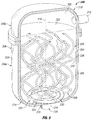
- FIG. 2 illustrates a perspective view of an exemplary reactor vessel, with a portion removed for visibility, which may be used in the gas turbine system of FIG. 1 , according to one or more embodiments of the disclosure.
- FIG. 3A illustrates a rear view of a fluid distribution system for the reactor vessel, according to one or more embodiments of the disclosure.
- FIG. 3B illustrates a top view of the fluid distribution system of FIG. 3A , according to one or more embodiments of the disclosure.
- FIG. 3C illustrates an isometric view of the fluid distribution system of FIGS. 3A and 3B , according to one or more embodiments of the disclosure.
- FIG. 3D illustrates an enlarged view of the portion of the fluid distribution system indicated by the box labeled 3 D of FIG. 3C , according to one or more embodiments of the disclosure.
- first and second features are formed in direct contact
- additional features may be formed interposing the first and second features, such that the first and second features may not be in direct contact.
- exemplary embodiments presented below may be combined in any combination of ways, i.e., any element from one exemplary embodiment may be used in any other exemplary embodiment, without departing from the scope of the disclosure.
- FIG. 1 illustrates a schematic of an exemplary gas turbine system 100 , according to one or more embodiments of the disclosure.
- the gas turbine system 100 may be configured to oxidize fuel and use the heat energy released by the oxidation process to generate mechanical energy and, in some embodiments, to generate electrical power.
- the fuel may be a component of a fluid mixture supplied at least in part by an oxygen source 102 and a fuel source 104 in fluid communication with the gas turbine system 100 .
- the gas turbine system 100 illustrated in FIG. 1 may oxidize all or substantially all of the fuel component of the fluid mixture, such that little or no fuel is wasted or discharged into the environment.
- FIG. 2 illustrates a perspective view of the reactor vessel 200 , with a portion removed for visibility, which may be used in place of the reactor vessel 106 of the gas turbine system 100 of FIG. 1 , according to one or more embodiments of the disclosure.
- the reactor vessel 200 may be configured to receive the fluid mixture and to oxidize the fuel component of the fluid mixture in a reaction chamber 202 defined by an interior perimeter 204 of a housing 206 of the reactor vessel 200 .
- the reactor vessel 200 may include a fluid distribution system 208 disposed within the reaction chamber 202 and configured to distribute the fluid mixture including at least the fuel component and an oxygen component from the oxygen source 102 throughout one or more oxidation zones in the reaction chamber 202 where the fuel component of the fluid mixture is oxidized.
- the fluid distribution system 208 may distribute the fluid mixture into multiple locations in one or more oxidation zones of the reaction chamber 202 , thereby sustaining oxidation by receiving heat from the reaction chamber 202 but imparting heat of oxidation back to the reaction chamber 202 to sustain a continuous oxidation process as additional fluid mixture flows into the reaction chamber 202 .
- the fuel source 104 may be configured to provide the fuel component of the fluid mixture to the gas turbine system 100 for sustaining the oxidation process in the reaction chamber 202 .
- the fuel source may be, in one or more embodiments, a subterranean well, a pipeline, a storage tank, or an output or byproduct from another chemical process at the site of the gas turbine system 100 .
- the fuel source may be or include a hydrocarbon well, a hydrocarbon pipeline, a cattle belch, a swampland, a rice farm, and fermented organic matter.
- Other fuel source examples may be or include manure, municipal waste, wetlands, and drilling and recover operations.
- the fuel source 104 may provide a single type of fuel and/or multiple types of fuels, one or all of which may be oxidized in the same reaction chamber 202 .
- the fuel source may provide hydrocarbon fuels including, but not limited to, methane, ethane, propane, butane, kerosene, and gasoline.
- the fuel source may provide a fuel including include nitrogen or carbon dioxide in addition to one or more hydrocarbons.
- the fuel source may provide hydrogen fuel.
- the fuel provided by the fuel source 104 to the gas turbine system 100 may be initially gaseous or may be in a liquid or solid phase before being converted to a gas or vapor.
- the fuel source may include a gasifier that generates gaseous fuel from solids.
- the fuel source may provide fuel mixed with water, and fuel from the fuel source 104 includes water vapor.
- the oxygen source 102 may be configured to provide oxygen for the oxidation process in the reaction chamber 202 .
- the oxygen source 102 may provide a gas containing oxygen, which may be mixed with the fuel from the fuel source 104 prior to oxidizing the fuel component of the fluid mixture.
- the oxygen source 102 may be or include air from the atmosphere surrounding the gas turbine system 100 .
- the oxygen source 102 may be or include air from a tank or cylinder of compressed or non-compressed air.
- the air provided from the oxygen source 102 may contain oxygen at any concentration sufficient for the oxidation of the fuel.
- the air provided from the oxygen source 102 may include other gases including, but not limited to, nitrogen and argon.
- the gas turbine system 100 may further include a compressor 108 and a gas expander 110 .
- the gas turbine system 100 may also include a generator 112 .
- the generator 112 may be mechanically coupled to the gas expander 110 via a common shaft 114 .
- a rotary shaft (not shown) of the generator 112 and a drive shaft (not shown) of the gas expander 110 may be coupled via a coupling or a gearbox (not shown).
- the heat energy released by the oxidation process in the reactor vessel 200 may be converted to mechanical energy via the gas expander 110 .
- the converted mechanical energy of the gas expander 110 may drive the generator 112 directly via the common shaft 114 , or indirectly via the gearbox, thereby generating electrical power.
- the generated electrical power may be used to power other components (e.g., actuators, control systems, sensors, and electric motors) of the gas turbine system 100 or may be provided to an electrical grid 116 in electrical communication with the gas turbine system 100 .
- the compressor 108 may be coupled to the gas expander 110 via the common shaft 114 .
- a rotary shaft (not shown) of the compressor 108 and a drive shaft (not shown) of the gas expander 110 may be coupled via a coupling or a gearbox (not shown).
- the gas expander 110 may drive the compressor 108 directly via the common shaft 114 , or indirectly via the gearbox.
- the compressor 108 may be operative coupled to and driven by a driver other than the gas expander 110 .
- the driver may be a motor and more specifically may be an electric motor, such as a permanent magnet motor, and may include a stator (not shown) and a rotor (not shown).
- driver may also be a hydraulic motor, an internal combustion engine, a steam turbine, or any other device capable of driving the compressor either directly or through a power train.
- the compressor 108 may be fluidly coupled to the fuel source 104 and the oxygen source 102 via lines 118 , 120 , and 122 . Accordingly, the oxygen provided from the oxygen source 102 and the fuel provided from the fuel source 104 may be mixed with one another and the resulting fluid mixture having a fuel component and an oxygen component may be fed to the compressor 108 via line 118 .
- the gas turbine system 100 may further include a mixer (not shown) configured to receive a fluid including oxygen from the oxygen source 102 via line 120 and a fluid including fuel from the fuel source 104 via line 122 to mix the fluids received and to provide the resulting fluid mixture to the compressor 108 via line 118 .
- the oxygen may be mixed with the fuel without a mixer.
- the oxygen may be fed via line 120 to mix with the fuel in line 122 and form the fluid mixture within line 122 before proceeding to the compressor 108 via line 118 .
- the fluid mixture provided to the compressor 108 may be a homogeneous mixture, or in some embodiments, may be a heterogeneous mixture.
- the compressor 108 may be configured to compress the fluid mixture provided from the fuel source 104 and the oxygen source 102 .
- the fluid mixture may flow through a compressor inlet (not shown) of the compressor 108 , where the fluid mixture in an exemplary embodiment may be drawn to and through an impeller (not shown) of the compressor 108 driven by the gas expander 110 , thereby increasing the static pressure and/or velocity of the fluid mixture.
- the fluid mixture may be directed to a diffuser (not shown) of the compressor 108 , where kinetic energy of the fluid mixture is converted into increased static pressure.
- the compressed fluid mixture may be discharged from the compressor 108 to line 124 via a compressor outlet (not shown).
- the gas turbine system 100 may also include a heat exchanger 126 fluidly coupled with the compressor 108 via line 124 and configured to pre-heat the fluid mixture received from the compressor 108 prior to the fluid mixture being fed into the reactor vessel 200 .
- the heat exchanger 126 may also be fluidly coupled with the gas expander 110 and configured to receive exhaust gas from the gas expander 110 via line 128 .
- the heat exchanger 126 may utilize heat provided from the exhaust gas to pre-heat the fluid mixture flowing therethrough.
- the heat exchanger 126 may transfer thermal energy from the higher temperature exhaust gas provided by the gas expander 110 to the lower temperature fluid mixture received from the compressor 108 , thereby pre-heating the fluid mixture.
- the heat exchanger 126 may be in some embodiments a gas-to-gas heat exchanger, such as a shell and tube heat exchanger, adapted to also receive a flow of the exhaust gas as a heating medium for increasing the temperature of the fluid mixture.
- the heat exchanger 126 may be a plate/fin heat exchanger or a printed circuit heat exchanger, without departing from the scope of the disclosure.
- the heat exchanger 126 may utilize heat provided from an external source (e.g., waste heat stream) in place of or in addition to the exhaust gas from the gas expander 110 to pre-heat the fluid mixture flowing therethrough.
- the reactor vessel 200 may be fluidly coupled with the heat exchanger 126 and thus may receive the pre-heated fluid mixture from the heat exchanger 126 via line 130 .
- the reactor vessel 200 may be directly fluidly coupled to the compressor 108 , such that the compressor 108 may communicate the fluid mixture into the reactor vessel 200 without the fluid mixture being pre-heated.
- the reaction chamber 202 may be configured to retain the fluid mixture received from the heat exchanger 126 , or compressor 108 in other embodiments, and to retain the fluid mixture in the reaction chamber 202 as the fuel component of the fluid mixture oxidizes.
- the reactor vessel 200 may have a longitudinal axis 210 extending along an axial length of the reactor vessel 200 , and the housing 206 of the reactor vessel 200 may form or be coupled to a vessel inlet 212 at an axial end 214 thereof.
- the vessel inlet 212 may be in fluid communication with the heat exchanger 126 (or compressor 108 in embodiments in which the heat exchanger 126 is absent), such that the fluid mixture may enter the reaction chamber 202 via line 130 and the vessel inlet 212 .
- the housing 206 of the reactor vessel 200 may form or be coupled to a vessel outlet 216 at an axial end 218 thereof axially opposing the vessel inlet 212 .
- the vessel outlet 216 may be in fluid communication with the gas expander 110 , such that the oxidized fluid mixture may exit the reaction chamber 202 via the vessel outlet 216 and line 132 and enter the gas expander 110 .
- the housing 206 may be a single unitary piece (not shown) or may be formed from separate housing components 206 a and 206 b as illustrated in FIG. 2 .
- the separate housing components 206 a , 206 b may include a first housing component 206 a including the vessel inlet 212 and a generally cylindrical sidewall 220 , and a second housing component 206 b including the vessel outlet 216 .
- the first and second housing components 206 a , 206 b may be coupled to each other via one or more fasteners (not shown).
- Exemplary fasteners include, but are not limited to, bolts, clamps, and the like.
- the interior perimeter 204 or inner surface of the housing 206 defining the reaction chamber 202 may be lined with insulating refractory material.
- the reaction chamber 202 may be filled with a solid particulate, referred to as filler material 222 .
- the filler material 222 may be a high temperature, heat-absorbing and/or heat-resistant material, such as ceramic or rock.
- the filler material 222 may have a thermal mass that stabilizes temperatures for gradual oxidation of the fuel by transmitting heat to the incoming gases of the fluid mixture and receiving heat from the oxidized gases.
- the thermal mass of the refractory material liner in the reaction chamber 202 may act as a dampener, absorbing heat and preventing excessive temperatures that could damage the gas expander 110 and/or produce unwanted byproducts (e.g., nitrogen oxides, carbon dioxides, volatile organic compounds and/or others). In some cases, the thermal mass of the refractory material liner in the reaction chamber 202 may provide a temporary source of heat energy, which may help sustain oxidation of the fuel.
- the reaction chamber 202 defined by the inner perimeter 204 of the housing 206 may have any geometry and/or orientation, and may define a primary direction of flow of the fluid mixture through the reaction chamber 202 (e.g., from the vessel inlet 212 to the vessel outlet 216 ) dependent on the structure of the reaction chamber 202 .
- the reaction chamber 202 shown in FIG. 2 has an internal geometry with a vessel outlet 216 near the upper axial end 218 of the reaction chamber 202 .
- the fluid mixture flows through the reaction chamber 202 primarily in an upward direction.
- there may be non-primary flows such as localized swirls, eddies, slipstreams and otherwise.
- the volume and shape of the reaction chamber 202 in conjunction with the fluid distribution system 208 may be sized and configured to provide a controlled flow and flow rate through the reaction chamber 202 to allow for sufficient dwell time for the complete oxidation of the fuel component of the fluid mixture.
- the reactor vessel 200 may include one or more sensors (not shown) disposed in the reaction chamber 202 and configured to detect properties such as temperature, pressure, flow rate, or other properties relevant to the startup and/or operation of the gas turbine system 100 .
- the reaction chamber 202 may also include internal structures and/or devices (not shown) that control aspects of the oxidation process.
- the reaction chamber may include flow diverters, valves, and/or other features that control temperature, pressure, flow rate, and/or other aspects of fluids in the reaction chamber 202 .
- FIGS. 3A-3D further illustrate multiple views of the fluid distribution system 208 .
- FIGS. 3A-3C illustrate respective rear, top, and isometric views of the fluid distribution system 208 of FIG. 2 , according to one or more embodiments of the disclosure.
- FIG. 3D illustrates an enlarged view of the portion of the fluid distribution system 208 indicated by the box labeled 3 D of FIG. 3C , according to one or more embodiments of the disclosure.
- the fluid distribution system 208 may be disposed within the reaction chamber 202 and fluidly coupled with the vessel inlet 212 . As arranged, the fluid distribution system 208 may be configured to disperse the fluid mixture into the reaction chamber 202 in multiple locations therein to distribute the fluid mixture substantially throughout the reaction chamber 202 . In an exemplary embodiment, the fluid distribution system 208 may distribute the fluid mixture such that heat released by oxidization of the fuel component in the fluid mixture maintains a temperature substantially throughout the reaction chamber 202 at a temperature sufficient to oxidize the fuel component in the fluid mixture.
- the fluid distribution system 208 may include a radial distribution component 224 and an axial distribution component 226 fluidly coupled with one another.
- the radial distribution component 224 may be disposed adjacent the vessel inlet 212 and may include a fluid distribution system inlet 228 fluidly coupled with the vessel inlet 212 and one or more annular distribution conduits 230 (two are shown) fluidly coupled with one another and with the fluid distribution system inlet 228 .
- annular distribution conduits 230 are illustrated, one of ordinary skill in the art will be appreciate that the disclosure is not limited thereto, and the fluid distribution system 208 may include one annular distribution conduit 230 in one embodiment, and in other embodiments, the distribution may include three or more annular distribution conduits 230 .
- the fluid distribution system inlet 228 may have a radially extending portion 232 and an axially extending portion 234 , thereby forming an elbow fluidly connecting the vessel inlet 212 and the annular distribution conduits 230 .
- the fluid distribution system inlet 228 may form a T-shape, thereby fluidly connecting the vessel inlet 212 and the one or more annular distribution conduits 230 .
- the configuration of the fluid distribution system inlet 228 may vary based at least on the fluid mixture, the flow rate of the fluid mixture, the configuration of the reaction chamber 202 and the components included therein.
- the fluid distribution system inlet 228 may be configured to position the annular distribution conduits 230 adjacent, e.g., in close proximity to, the axial end 214 of the reactor vessel 200 having the vessel inlet 212 .
- the annular distribution conduits 230 may be less susceptible to axial relative motions during thermal transients.
- the annular distribution conduits 230 may be disposed in a nesting relationship such that each annular distribution conduit 230 is radially offset from another annular distribution conduit 230 as disposed in the reaction chamber 202 . As arranged, the annular distribution conduits 230 may be concentric, and each annular distribution conduit 230 may have opposing ends terminating in the fluid distribution system inlet 228 , such that fluid communication may be provided between the fluid distribution system inlet 228 and the respective annular distribution conduit 230 .
- each end of the annular distribution conduit 230 is fluidly coupled with the fluid distribution system inlet 228 along the radially extending portion thereof 232 ; however, one of ordinary skill in the art will be appreciate that the disclosure is not limited thereto, and each end of the annular distribution conduit 230 may be fluidly coupled with the fluid distribution system inlet 228 along the axially extending portion 234 thereof in some embodiments.
- the axial distribution component 226 of the fluid distribution system 208 may be fluidly coupled with the radial distribution component 224 and disposed within the reaction chamber 202 .
- the axial distribution component 226 may include a plurality of helical conduits 236 extending from the annular distribution conduits 230 and along the longitudinal axis 210 of the reactor vessel 200 .
- the axial distribution component 226 may include a plurality of helical conduits 236 extending from the fluid distribution system inlet 228 and along the longitudinal axis 210 of the reactor vessel 200 .
- the axial distribution component 226 may include a plurality of helical conduits 236 extending from the fluid distribution system inlet 228 and one or more of the annular distribution conduits 230 and along the longitudinal axis 210 of the reactor vessel 200 . As illustrated in FIG. 2 , the plurality of helical conduits 236 may extend from the fluid distribution system inlet 228 and each of the annular distribution conduits 230 and along the longitudinal axis 210 of the reactor vessel 200 .
- the plurality of helical conduits 236 may be fluidly coupled with the annular distribution conduits 230 and arranged circumferentially spaced from one another along each annular distribution conduit 230 .
- each of the helical conduits 236 is uniformly spaced from one another along each annular distribution conduit 230 .
- the plurality of helical conduits 236 may be configured to provide a uniform spatial distribution of the fluid mixture flowing therethrough and into the reaction chamber 202 .
- the number of helical conduits 236 in the axial distribution component 226 may be based at least in part on the intended flow capacity of the fluid distribution system 208 including the radial distribution component 224 thereof.
- each of the helical conduits 236 may extend substantially the axial length of the reaction chamber 202 .
- each of the helical conduits may have a helix axis 238 about which the helical conduit 236 turns or curves in a spiral form.
- Each complete turn (360 degree turn) of the helical conduit 236 about the helix axis 238 may define the diameter 240 of the helical conduit.
- the diameter 240 of each of the helical conduits 236 may be about a third of a lateral diameter 242 of the reaction chamber.
- a tangent line 244 at any point along the helical conduit 236 may make a constant angle ⁇ with a transverse axis 246 perpendicular to the helix axis 238 .
- Such an angle ⁇ may be referred to herein as a helix angle ⁇ and is illustrated most clearly in FIG. 3A .
- the helix angle ⁇ may be greater than about forty-five degrees to minimize relative movement effects.
- the helix angle ⁇ may be greater than about fifty degrees.
- the helix angle ⁇ may be greater than about fifty-five degrees.
- the helix angle ⁇ may be greater than about sixty degrees.
- each helical conduit 236 may have a tubular sidewall 248 forming one or more nozzles 250 configured to spatially distribute the fluid mixture into the reaction chamber 202 .
- each of the one or more nozzles 250 may be cast as a separate piece and may be coupled to the helical conduit 236 via a welded connection or other suitable coupling or fastening method known in the art.
- Each nozzle 250 may be formed from a generally conical inward distortion 252 and a generally conical outward distortion 254 of the tubular sidewall 248 defining a fluid dispersion orifice 256 oriented to disperse fluid mixture flowing therethrough toward the vessel inlet 212 as indicated by arrow F.
- One or more of the fluid dispersion orifices 256 may be sized and configured to provide a fixed flow capacity with a favorable pressure drop and flow dispersion characteristics.
Landscapes
- Chemical & Material Sciences (AREA)
- Chemical Kinetics & Catalysis (AREA)
- Engineering & Computer Science (AREA)
- Organic Chemistry (AREA)
- Combustion & Propulsion (AREA)
- Mechanical Engineering (AREA)
- General Engineering & Computer Science (AREA)
- Dispersion Chemistry (AREA)
- Physical Or Chemical Processes And Apparatus (AREA)
Abstract
Description
Claims (15)
Priority Applications (1)
| Application Number | Priority Date | Filing Date | Title |
|---|---|---|---|
| US16/349,726 US10894236B2 (en) | 2016-11-30 | 2017-11-28 | Radial annular component and helical axial components coupled to and extending from the radial component |
Applications Claiming Priority (3)
| Application Number | Priority Date | Filing Date | Title |
|---|---|---|---|
| US201662428087P | 2016-11-30 | 2016-11-30 | |
| PCT/US2017/063384 WO2018102284A1 (en) | 2016-11-30 | 2017-11-28 | Fluid distribution system for a reactor vessel |
| US16/349,726 US10894236B2 (en) | 2016-11-30 | 2017-11-28 | Radial annular component and helical axial components coupled to and extending from the radial component |
Publications (2)
| Publication Number | Publication Date |
|---|---|
| US20200055008A1 US20200055008A1 (en) | 2020-02-20 |
| US10894236B2 true US10894236B2 (en) | 2021-01-19 |
Family
ID=60813971
Family Applications (1)
| Application Number | Title | Priority Date | Filing Date |
|---|---|---|---|
| US16/349,726 Active US10894236B2 (en) | 2016-11-30 | 2017-11-28 | Radial annular component and helical axial components coupled to and extending from the radial component |
Country Status (2)
| Country | Link |
|---|---|
| US (1) | US10894236B2 (en) |
| WO (1) | WO2018102284A1 (en) |
Families Citing this family (1)
| Publication number | Priority date | Publication date | Assignee | Title |
|---|---|---|---|---|
| WO2019012176A1 (en) * | 2017-07-11 | 2019-01-17 | Outotec (Finland) Oy | Sparger apparatus |
Citations (16)
| Publication number | Priority date | Publication date | Assignee | Title |
|---|---|---|---|---|
| US4198360A (en) | 1978-10-03 | 1980-04-15 | Baskov Jury A | Apparatus for heat-mass exchange processes with participation of liquid |
| US6250796B1 (en) * | 1994-12-28 | 2001-06-26 | Weimin Huang | Agitation apparatus with static mixer or swirler means |
| US20090158743A1 (en) * | 2007-12-19 | 2009-06-25 | Rolls-Royce Plc | Fuel distribution apparatus |
| US20100275611A1 (en) * | 2009-05-01 | 2010-11-04 | Edan Prabhu | Distributing Fuel Flow in a Reaction Chamber |
| WO2011027570A1 (en) * | 2009-09-04 | 2011-03-10 | 日曹エンジニアリング株式会社 | Flow-type tubular reactor |
| US20110199855A1 (en) | 2008-10-20 | 2011-08-18 | Asahi Organic Chemicals Industry Co., Ltd. | Spiral type fluid mixer and apparatus using spiral type fluid mixer |
| US20120137696A1 (en) | 2010-12-06 | 2012-06-07 | General Electric Company | Air-staged diffusion nozzle |
| US20120152722A1 (en) * | 2010-07-01 | 2012-06-21 | Advanced Fusion Systems Llc | Method of Inducing Chemical Reactions |
| RU2506495C1 (en) | 2012-11-22 | 2014-02-10 | Андрей Владиславович Курочкин | Device for combustion of fuels and heating of process media, and fuel combustion method |
| US20140352321A1 (en) | 2012-11-30 | 2014-12-04 | General Electric Company | Gas turbine engine system and an associated method thereof |
| US8926917B2 (en) * | 2012-03-09 | 2015-01-06 | Ener-Core Power, Inc. | Gradual oxidation with adiabatic temperature above flameout temperature |
| US20150047361A1 (en) | 2013-02-06 | 2015-02-19 | Siemens Aktiengesellschaft | Nozzle with multi-tube fuel passageway for gas turbine engines |
| US20150129475A1 (en) | 2013-11-13 | 2015-05-14 | Axiall Ohio, Inc. | Chemical Feeder |
| US20160102631A1 (en) | 2013-04-29 | 2016-04-14 | Xeicle Limited | A thermodynamic machine |
| US20170165632A1 (en) * | 2015-12-09 | 2017-06-15 | Blacktrace Holdings Limited | Reactor device for reaction fluid |
| US20170248318A1 (en) * | 2016-02-26 | 2017-08-31 | General Electric Company | Pilot nozzles in gas turbine combustors |
-
2017
- 2017-11-28 US US16/349,726 patent/US10894236B2/en active Active
- 2017-11-28 WO PCT/US2017/063384 patent/WO2018102284A1/en not_active Ceased
Patent Citations (16)
| Publication number | Priority date | Publication date | Assignee | Title |
|---|---|---|---|---|
| US4198360A (en) | 1978-10-03 | 1980-04-15 | Baskov Jury A | Apparatus for heat-mass exchange processes with participation of liquid |
| US6250796B1 (en) * | 1994-12-28 | 2001-06-26 | Weimin Huang | Agitation apparatus with static mixer or swirler means |
| US20090158743A1 (en) * | 2007-12-19 | 2009-06-25 | Rolls-Royce Plc | Fuel distribution apparatus |
| US20110199855A1 (en) | 2008-10-20 | 2011-08-18 | Asahi Organic Chemicals Industry Co., Ltd. | Spiral type fluid mixer and apparatus using spiral type fluid mixer |
| US20100275611A1 (en) * | 2009-05-01 | 2010-11-04 | Edan Prabhu | Distributing Fuel Flow in a Reaction Chamber |
| WO2011027570A1 (en) * | 2009-09-04 | 2011-03-10 | 日曹エンジニアリング株式会社 | Flow-type tubular reactor |
| US20120152722A1 (en) * | 2010-07-01 | 2012-06-21 | Advanced Fusion Systems Llc | Method of Inducing Chemical Reactions |
| US20120137696A1 (en) | 2010-12-06 | 2012-06-07 | General Electric Company | Air-staged diffusion nozzle |
| US8926917B2 (en) * | 2012-03-09 | 2015-01-06 | Ener-Core Power, Inc. | Gradual oxidation with adiabatic temperature above flameout temperature |
| RU2506495C1 (en) | 2012-11-22 | 2014-02-10 | Андрей Владиславович Курочкин | Device for combustion of fuels and heating of process media, and fuel combustion method |
| US20140352321A1 (en) | 2012-11-30 | 2014-12-04 | General Electric Company | Gas turbine engine system and an associated method thereof |
| US20150047361A1 (en) | 2013-02-06 | 2015-02-19 | Siemens Aktiengesellschaft | Nozzle with multi-tube fuel passageway for gas turbine engines |
| US20160102631A1 (en) | 2013-04-29 | 2016-04-14 | Xeicle Limited | A thermodynamic machine |
| US20150129475A1 (en) | 2013-11-13 | 2015-05-14 | Axiall Ohio, Inc. | Chemical Feeder |
| US20170165632A1 (en) * | 2015-12-09 | 2017-06-15 | Blacktrace Holdings Limited | Reactor device for reaction fluid |
| US20170248318A1 (en) * | 2016-02-26 | 2017-08-31 | General Electric Company | Pilot nozzles in gas turbine combustors |
Non-Patent Citations (1)
| Title |
|---|
| PCT International Search Report and Written Opinion dated Feb. 16, 2018 corresponding to PCT Application No. PCT/US2017/063384 filed Nov. 28, 2017. |
Also Published As
| Publication number | Publication date |
|---|---|
| US20200055008A1 (en) | 2020-02-20 |
| WO2018102284A1 (en) | 2018-06-07 |
Similar Documents
| Publication | Publication Date | Title |
|---|---|---|
| US11781747B2 (en) | Method and apparatus for setting the ignition property of a fuel | |
| KR101237891B1 (en) | High shear process for air/fuel mixing | |
| CN105637206B (en) | System and method for exhausting combustion gases from a gas turbine engine | |
| US20100275611A1 (en) | Distributing Fuel Flow in a Reaction Chamber | |
| US9132385B2 (en) | System and method to gasify aqueous urea into ammonia vapors using secondary flue gases | |
| US12258977B2 (en) | Rotary device for inputting thermal energy into fluids | |
| CN104903672A (en) | High efficiency direct contact heat exchanger | |
| US9255507B2 (en) | Reagent injection system for exhaust of turbine system | |
| US10894236B2 (en) | Radial annular component and helical axial components coupled to and extending from the radial component | |
| JP6176023B2 (en) | Equipment for reforming tar in gasification gas | |
| US7955567B2 (en) | Triple helical flow vortex reactor improvements | |
| JP2017519175A (en) | Implosion type reactor tube | |
| CN116608465A (en) | Ammonia burner with space grading ammonia injection function | |
| JP7598723B2 (en) | Gasifier | |
| US20250243780A1 (en) | Rotary device for inputting thermal energy into fluids and related systems | |
| WO2025003654A1 (en) | Reactor module | |
| US20150315018A1 (en) | Mixing device for a fuel reformer for converting hydrocarbon fuels into hydrogen rich gas | |
| EP4015811B1 (en) | A system for recovery of energy from a residual gas | |
| JP2019127539A (en) | Gasification system | |
| CN103159312B (en) | The device and method of controlled oxidization conversion zone | |
| CN118973702A (en) | Reactor for converting chemical compounds into materials, gases or energy and use thereof | |
| CN116147376A (en) | A multi-angle distributed heat mixer device | |
| WO2024132251A1 (en) | Fluid reactor devices, methods for operating a fluid reactor device, method for maintaining a fluid reactor device and method for installing a fluid reactor device | |
| CN102235237A (en) | Hydrocarbon and water hybrid engine | |
| KR20260057076A (en) | Rotating device for heating a fluid and recirculating the heated fluid, related method and use |
Legal Events
| Date | Code | Title | Description |
|---|---|---|---|
| AS | Assignment |
Owner name: DRESSER-RAND COMPANY, NEW YORK Free format text: ASSIGNMENT OF ASSIGNORS INTEREST;ASSIGNORS:MAIER, WILLIAM C.;WISLER, SCOTT DAVID;REEL/FRAME:049171/0597 Effective date: 20161207 |
|
| FEPP | Fee payment procedure |
Free format text: ENTITY STATUS SET TO UNDISCOUNTED (ORIGINAL EVENT CODE: BIG.); ENTITY STATUS OF PATENT OWNER: LARGE ENTITY |
|
| STPP | Information on status: patent application and granting procedure in general |
Free format text: NOTICE OF ALLOWANCE MAILED -- APPLICATION RECEIVED IN OFFICE OF PUBLICATIONS |
|
| STPP | Information on status: patent application and granting procedure in general |
Free format text: PUBLICATIONS -- ISSUE FEE PAYMENT VERIFIED |
|
| STCF | Information on status: patent grant |
Free format text: PATENTED CASE |
|
| AS | Assignment |
Owner name: SIEMENS ENERGY, INC., FLORIDA Free format text: MERGER;ASSIGNOR:DRESSER-RAND COMPANY;REEL/FRAME:062921/0538 Effective date: 20221205 |
|
| MAFP | Maintenance fee payment |
Free format text: PAYMENT OF MAINTENANCE FEE, 4TH YEAR, LARGE ENTITY (ORIGINAL EVENT CODE: M1551); ENTITY STATUS OF PATENT OWNER: LARGE ENTITY Year of fee payment: 4 |