US10888990B2 - Hot stick device with push button connector and related methods - Google Patents
Hot stick device with push button connector and related methods Download PDFInfo
- Publication number
- US10888990B2 US10888990B2 US16/601,735 US201916601735A US10888990B2 US 10888990 B2 US10888990 B2 US 10888990B2 US 201916601735 A US201916601735 A US 201916601735A US 10888990 B2 US10888990 B2 US 10888990B2
- Authority
- US
- United States
- Prior art keywords
- distal end
- tool
- connector body
- connector
- threaded
- Prior art date
- Legal status (The legal status is an assumption and is not a legal conclusion. Google has not performed a legal analysis and makes no representation as to the accuracy of the status listed.)
- Active
Links
- 238000000034 method Methods 0.000 title claims description 18
- 238000013459 approach Methods 0.000 description 3
- 239000004020 conductor Substances 0.000 description 2
- 230000008878 coupling Effects 0.000 description 2
- 238000010168 coupling process Methods 0.000 description 2
- 238000005859 coupling reaction Methods 0.000 description 2
- 238000012423 maintenance Methods 0.000 description 2
- 239000000463 material Substances 0.000 description 2
- 238000012986 modification Methods 0.000 description 2
- 230000004048 modification Effects 0.000 description 2
- 238000013138 pruning Methods 0.000 description 2
- 244000007853 Sarothamnus scoparius Species 0.000 description 1
- 229910010293 ceramic material Inorganic materials 0.000 description 1
- 239000003989 dielectric material Substances 0.000 description 1
- 239000011810 insulating material Substances 0.000 description 1
- 239000007769 metal material Substances 0.000 description 1
- 239000003973 paint Substances 0.000 description 1
- 238000010422 painting Methods 0.000 description 1
- 229920000642 polymer Polymers 0.000 description 1
Images


Classifications
-
- B—PERFORMING OPERATIONS; TRANSPORTING
- B25—HAND TOOLS; PORTABLE POWER-DRIVEN TOOLS; MANIPULATORS
- B25G—HANDLES FOR HAND IMPLEMENTS
- B25G3/00—Attaching handles to the implements
- B25G3/38—Hinged, pivoted, swivelling, or folding joints
-
- B—PERFORMING OPERATIONS; TRANSPORTING
- B25—HAND TOOLS; PORTABLE POWER-DRIVEN TOOLS; MANIPULATORS
- B25G—HANDLES FOR HAND IMPLEMENTS
- B25G1/00—Handle constructions
- B25G1/10—Handle constructions characterised by material or shape
- B25G1/12—Handle constructions characterised by material or shape electrically insulating material
-
- B—PERFORMING OPERATIONS; TRANSPORTING
- B25—HAND TOOLS; PORTABLE POWER-DRIVEN TOOLS; MANIPULATORS
- B25G—HANDLES FOR HAND IMPLEMENTS
- B25G3/00—Attaching handles to the implements
- B25G3/02—Socket, tang, or like fixings
- B25G3/12—Locking and securing devices
- B25G3/14—Locking and securing devices comprising barbs or teeth
-
- B—PERFORMING OPERATIONS; TRANSPORTING
- B25—HAND TOOLS; PORTABLE POWER-DRIVEN TOOLS; MANIPULATORS
- B25G—HANDLES FOR HAND IMPLEMENTS
- B25G3/00—Attaching handles to the implements
- B25G3/02—Socket, tang, or like fixings
- B25G3/12—Locking and securing devices
- B25G3/26—Locking and securing devices comprising nails, screws, bolts, or pins traversing or entering the socket
-
- H—ELECTRICITY
- H02—GENERATION; CONVERSION OR DISTRIBUTION OF ELECTRIC POWER
- H02G—INSTALLATION OF ELECTRIC CABLES OR LINES, OR OF COMBINED OPTICAL AND ELECTRIC CABLES OR LINES
- H02G1/00—Methods or apparatus specially adapted for installing, maintaining, repairing or dismantling electric cables or lines
- H02G1/02—Methods or apparatus specially adapted for installing, maintaining, repairing or dismantling electric cables or lines for overhead lines or cables
Definitions
- the present disclosure relates to the field of tool devices, and, more particularly, to an electrical hot stick device and related methods.
- Hot stick devices are typically constructed of a suitable dielectric material and include a tool holder at a distal end. The tool holder is adaptable to engage a wide array of different tools.
- the hot stick device allows a user to perform a wide variety of tasks such as opening and closing various types of switches, replacing fuses, pruning tree limbs or replacing lamps in street circuits and rooms with high ceilings. Since the workpiece may be as far as 30 feet or more away from a user, telescoping hot stick devices or poles provide a variable length to accommodate these tasks.
- the hot stick device includes a tool holder permitting rotational adjustment of the tool attached to the tool holder.
- the tool engages radial teeth of the tool holder, and is manually clamped via a threaded stud and nut arrangement.
- One issue with these rotatable tool hot stick devices is that the user must manually rotate the tool by removing the threaded but and adjusting the tool. Since the user is usually elevated within a bucket truck, the user may struggle to adjust the tool, and may even drop the threaded nut while making the adjustment.
- a hot stick device may include an insulated shaft having a proximal end, and a distal end opposing the proximal end.
- the hot stick device may also include a tool connector including a connector body.
- the connector body may comprise a proximal end coupled to the distal end of the insulated shaft, a distal end, and first and second opposing longitudinal sides extending between the proximal end and the distal end of the connector body.
- the first longitudinal side of the connector body may include a first interlocking interface.
- the distal end may define a through passageway extending between the first and second opposing longitudinal sides.
- the tool connector also may include a fastener having a head, and a threaded shaft extending in the through passageway, a first threaded nut threadingly engaging the threaded shaft, and a spring device coupled between the head and the second longitudinal side.
- the hot stick device may comprise an accessory tool including a second interlocking interface to engage with the first interlocking interface and coupled between the first threaded nut and the connector body.
- the head of the fastener may be configured to longitudinally compress the spring device against the second longitudinal side, and longitudinally extend the threaded shaft and the first threaded nut thereon, thereby lifting the accessory tool and disengaging the first and second interlocking interfaces.
- the first interlocking interface may include a first inner radial shelf, and the distal end of the connector body may include a second inner radial shelf.
- the tool connector may include a second threaded nut positioned between the first inner radial shelf and adjacent portions of the second interlocking interface.
- the first threaded nut may include a threaded wing nut.
- Each of the first interlocking interface and the second interlocking interface may include alternating recesses and protrusions.
- the proximal end of the connector body may include a hexagon-shaped outer radial edge.
- the proximal end of the connector body may define a circle-shaped recess within the hexagon-shaped outer radial edge and configured to receive the distal end of the insulated shaft.
- the tool connector may include a washer coupled between the head and the spring device.
- the spring device may include a coil spring.
- the tool connector may comprise a connector body including a proximal end coupled to the distal end of the insulated shaft, a distal end, and first and second opposing longitudinal sides extending between the proximal end and the distal end of the connector body.
- the first longitudinal side of the connector body may include a first interlocking interface.
- the distal end may define a through passageway extending between the first and second opposing longitudinal sides.
- the tool connector may also include a fastener having a head, and a threaded shaft extending in the through passageway, a first threaded nut threadingly engaging the threaded shaft, and a spring device coupled between the head and the second longitudinal side.
- an accessory tool may have a second interlocking interface to engage with the first interlocking interface and is coupled between the first threaded nut and the connector body.
- the head of the fastener may be configured to longitudinally compress the spring device against the second longitudinal side, and longitudinally extend the threaded shaft and the first threaded nut thereon, thereby lifting the accessory tool and disengaging the first and second interlocking interfaces.
- the method may include forming a tool connector including a connector body including a proximal end coupled to a distal end of an insulated shaft, a distal end, and first and second opposing longitudinal sides extending between the proximal end and the distal end of the connector body.
- the first longitudinal side of the connector body may include a first interlocking interface.
- the distal end may define a through passageway extending between the first and second opposing longitudinal sides.
- the tool connector may also include a fastener having a head, and a threaded shaft extending in the through passageway, a first threaded nut threadingly engaging the threaded shaft, and a spring device coupled between the head and the second longitudinal side.
- the method may include providing an accessory tool including a second interlocking interface to engage with the first interlocking interface and coupled between the first threaded nut and the connector body.
- the head of the fastener may be configured to longitudinally compress the spring device against the second longitudinal side, and longitudinally extend the threaded shaft and the first threaded nut thereon, thereby lifting the accessory tool and disengaging the first and second interlocking interfaces.
- FIG. 1 is an exploded schematic view of a hot stick device, according to the present disclosure.
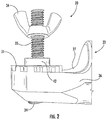
- FIG. 2 is a partial left side elevational schematic view of the hot stick device from FIG. 1 .
- FIG. 3 is a partial front side plan elevational schematic view of the hot stick device from FIG. 1 .
- FIG. 4 is a partial back side plan elevational schematic view of the tool connector of the hot stick device from FIG. 1 .
- FIG. 5 is a front side plan schematic view of the tool connector of the hot stick device from FIG. 1 .
- FIG. 6 is a right side elevational schematic view of the tool connector of the hot stick device from FIG. 1 .
- FIG. 7 is a top plan schematic view of the tool connector of the hot stick device from FIG. 1 .
- FIG. 8 is a bottom plan schematic view of the tool connector of the hot stick device from FIG. 1 .
- FIG. 9 is a back side plan schematic view of the tool connector of the hot stick device from FIG. 1 .
- FIG. 10 is a perspective schematic view of the tool connector of the hot stick device from FIG. 1 .
- FIG. 11 is another perspective schematic view of the tool connector of the hot stick device from FIG. 1 .
- the hot stick device 20 illustratively comprises an insulated shaft 21 ( FIG. 1 ) having a proximal end 22 a ( FIG. 1 ), and a distal end 22 b ( FIG. 1 ) opposing the proximal end.
- the insulated shaft 21 may comprise insulating material, such as a polymer plastic.
- the hot stick device 20 illustratively comprises a tool connector 23 having a connector body 24 comprising a proximal end 25 coupled to the distal end 22 b of the insulated shaft 21 , a distal end 26 , and first and second opposing longitudinal sides 27 , 30 extending between the proximal end and the distal end of the connector body.
- the proximal end 25 of the connector body 24 illustratively includes a circle-shaped recess 28 configured to receive the distal end 22 b of the insulated shaft 21 .
- this shape is merely exemplary and could comprise a rectangle shape, triangle shape, a polygon shape (e.g. hexagon, octagon) for instance.
- the first longitudinal side 27 of the connector body 24 illustratively comprises a first interlocking interface 31 .
- the first interlocking interface 31 illustratively comprises an outer radial pattern of alternating recesses and protrusions.
- Each of the recesses comprises a U-shaped recess opening radially outward, and having opposing sides canted from a normal position from a tangent of the outer radial edge.
- the opposing sides are canted between 5°-15° from a normal position from the tangent of the outer radial edge.
- the distal end 26 defines a through passageway 32 extending between the first and second opposing longitudinal sides 27 , 30 .
- the tool connector 23 illustratively includes a fastener 33 having a head 34 , and a threaded shaft 35 extending in the through passageway 32 , a first threaded nut 36 threadingly engaging the threaded shaft, and a spring device 37 coupled between the head and the second longitudinal side 30 .
- the tool connector 23 illustratively includes a washer 38 coupled between the head 34 and the spring device 37 for permitted the spring device to securely sit against the head.
- the threaded shaft 35 is inserted sequentially through the washer 38 , the spring device 37 and then in the through passageway 32 .
- the spring device 37 illustratively comprises a coil spring, for example.
- the first interlocking interface 31 illustratively includes a first inner radial shelf 43 circumscribing the through passageway 32 .
- the distal end 26 of the connector body 24 illustratively includes a second inner radial shelf 44 circumscribing the through passageway 32 .
- the hot stick device comprises an accessory tool 40 ( FIG. 1 ) comprising a second interlocking interface 41 to engage with the first interlocking interface 31 and coupled between the first threaded nut 36 and the connector body 24 .
- the second interlocking interface 41 illustratively comprises an outer radial pattern of alternating recesses and protrusions configured to engage the first interlocking interface 31 .
- the accessory tool 40 illustratively comprises a disconnect tool, but the accessory tool may comprise any hot stick accessory, such as a lighted disconnect tool, a pointed disconnect tool, a spiral disconnect tool, a S-hook tool, a blade tool, a fixed prong tool, a tie stick tool, a conductor brush tool, or a conductor cleaner tool, for example.
- a hot stick accessory such as a lighted disconnect tool, a pointed disconnect tool, a spiral disconnect tool, a S-hook tool, a blade tool, a fixed prong tool, a tie stick tool, a conductor brush tool, or a conductor cleaner tool, for example.
- the tool connector 23 may comprise a rigid material sufficient to mechanically support the accessory tool 40 .
- the rigid material comprise a metallic material, and/or a ceramic material, for example.
- the proximal end 25 of the tool connector 23 illustratively comprises a plurality of circle-shaped recesses 45 a - 45 b for aiding receiving of the insulated shaft 21 .
- the tool connector 23 illustratively comprises a second threaded nut 42 positioned between the first inner radial shelf 43 and adjacent portions of the second interlocking interface 41 .
- the second threaded nut 42 may comprise a standard flat-sided threaded nut, a self-clinching threaded nut, a flanged nut, and an unthreaded nut.
- the proximal end 25 of the tool connector 23 illustratively has a hexagon shape (i.e. so as to be rotated readily by a typical hand wrench tool), but may be circle-shaped or rectangle-shaped in some embodiments.
- the user In use, to assemble the hot stick device 20 , the user would sequentially insert the threaded fastener 33 through the washer 38 , the spring device 37 , and then in the through passageway 32 .
- the spring device would rest upon the second inner radial shelf 44 .
- the second threaded nut 42 would be threadingly engaged on the threaded shaft 35 until abutting the first inner radial shelf 43 , but not compressing the spring device 37 on the other side of the through passageway 32 .
- the accessory tool 40 of choice would be fitted over the distal end of the threaded shaft 35 so that the first and second interlocking interfaces 31 , 41 engage in the desired rotational position.
- the threaded shaft 35 would extend through the accessory tool 40 and be exposed on the opposite end.
- the first threaded nut 36 would be threadingly engaged over the exposed end of the threaded shaft 35 until a satisfactory fit has been provided.
- the hot stick device 20 may provide an approach to this issue. Rather than unfastening the first threaded nut 36 , the user may readily push down on the head 34 of the threaded fastener 33 , which will compress the spring device 37 longitudinally extending the second threaded nut 42 , thereby lifting the accessory tool 40 and also disengaging the first and second interlocking interfaces 31 , 41 .
- This free rotation mode is perhaps best seen in FIG. 2 where the second threaded nut 42 is exposed and visible. The user may then readily reposition the rotational position of the accessory tool 40 and release the head 34 , thereby reengaging the first and second interlocking interfaces 31 , 41 .
- a method for making a hot stick device 20 comprises forming a tool connector 23 .
- the tool connector 23 includes a connector body 24 comprising a proximal end 25 coupled to a distal end 22 b of an insulated shaft 21 , a distal end 26 , and first and second opposing longitudinal sides 27 , 30 extending between the proximal end and the distal end of the connector body.
- the first longitudinal side 27 of the connector body 24 includes a first interlocking interface 31
- the distal end 26 defines a through passageway 32 extending between the first and second opposing longitudinal sides 27 , 30 .
- the tool connector 23 comprises a fastener 33 having a head 34 , and a threaded shaft 35 extending in the through passageway 32 , a first threaded nut 36 threadingly engaging the threaded shaft, and a spring device 37 coupled between the head and the second longitudinal side 30 .
- the method comprises coupling an accessory tool 40 between the first threaded nut 36 and the connector body 24 , the accessory tool comprising a second interlocking interface 41 to engage with the first interlocking interface 31 .
- Yet another aspect is directed to a method for using/operating a hot stick device 20 .
- the method includes providing a tool connector 23 including a connector body 24 including a proximal end 25 coupled to a distal end 22 b of an insulated shaft 21 , a distal end 26 , and first and second opposing longitudinal sides 27 , 30 extending between the proximal end and the distal end of the connector body.
- the first longitudinal side 27 of the connector body 24 includes a first interlocking interface 31 .
- the distal end 26 defines a through passageway 32 extending between the first and second opposing longitudinal sides 27 , 30 .
- the tool connector 23 also includes a fastener 33 having a head 34 , and a threaded shaft 35 extending in the through passageway 32 , a first threaded nut 36 threadingly engaging the threaded shaft, and a spring device 37 coupled between the head and the second longitudinal side 30 .
- the method includes coupling an accessory tool 40 , the accessory tool including a second interlocking interface 41 to engage with the first interlocking interface 31 .
- the accessory tool 40 is coupled between the first threaded nut 36 and the connector body 24 .
- the method includes actuating or pushing the head 34 of the fastener 33 to longitudinally compress the spring device 37 against the second longitudinal side 30 , and longitudinally extend the threaded shaft 35 and the first threaded nut 36 thereon, thereby lifting the accessory tool 40 and disengaging the first and second interlocking interfaces 31 , 41 .
- the method also includes rotating the accessory tool 40 to a desired position, and releasing the head 34 of the fastener 33 .
- the disclosed push release of the connector body 24 can be applied in other tools where rotational adjustment is needed.
- the depicted hot stick device 20 is merely exemplary, and the teachings herein may applied to other tools, such as a concrete float tool, an arborist device (e.g. pruning device), painting devices (e.g. paint roller extension pole with rotating head) or a broom bracket.
Landscapes
- Engineering & Computer Science (AREA)
- Mechanical Engineering (AREA)
- Electric Cable Installation (AREA)
Abstract
Description
Claims (20)
Priority Applications (1)
| Application Number | Priority Date | Filing Date | Title |
|---|---|---|---|
| US16/601,735 US10888990B2 (en) | 2019-02-11 | 2019-10-15 | Hot stick device with push button connector and related methods |
Applications Claiming Priority (2)
| Application Number | Priority Date | Filing Date | Title |
|---|---|---|---|
| US201962803681P | 2019-02-11 | 2019-02-11 | |
| US16/601,735 US10888990B2 (en) | 2019-02-11 | 2019-10-15 | Hot stick device with push button connector and related methods |
Publications (2)
| Publication Number | Publication Date |
|---|---|
| US20200254603A1 US20200254603A1 (en) | 2020-08-13 |
| US10888990B2 true US10888990B2 (en) | 2021-01-12 |
Family
ID=71945791
Family Applications (1)
| Application Number | Title | Priority Date | Filing Date |
|---|---|---|---|
| US16/601,735 Active US10888990B2 (en) | 2019-02-11 | 2019-10-15 | Hot stick device with push button connector and related methods |
Country Status (1)
| Country | Link |
|---|---|
| US (1) | US10888990B2 (en) |
Families Citing this family (3)
| Publication number | Priority date | Publication date | Assignee | Title |
|---|---|---|---|---|
| USD921948S1 (en) * | 2019-02-12 | 2021-06-08 | Milwaukee Electric Tool Corporation | Light |
| US11986937B2 (en) * | 2020-01-24 | 2024-05-21 | The Wooster Brush Company | Tool holder including a threaded actuator |
| US12377530B2 (en) * | 2022-06-20 | 2025-08-05 | Randy Fabian Gurule | Pocket brush and tool holder |
Citations (16)
| Publication number | Priority date | Publication date | Assignee | Title |
|---|---|---|---|---|
| US2291593A (en) | 1941-08-13 | 1942-07-28 | Chance Co Ab | Operating tool for high tension electric lines |
| US2438504A (en) | 1944-11-23 | 1948-03-30 | Chance Co Ab | Storm attachment for high line tools |
| US3205522A (en) * | 1963-08-28 | 1965-09-14 | Karl P Then | Universally adjustable tool holder |
| US4848818A (en) * | 1988-01-19 | 1989-07-18 | Smith Gordon K | Gutter cleaning tool, with a multi-positional and self-locking joint, that can be remotely operated by hand from an oblique angle |
| US4917343A (en) * | 1985-09-16 | 1990-04-17 | Read-Eze Systems Limited | Adjustable support |
| US5547305A (en) * | 1995-03-02 | 1996-08-20 | The Whitaker Corporation | Rapid, tool-less adjusting system for hotstick tooling |
| US5564852A (en) | 1995-03-29 | 1996-10-15 | Burndy Corporation | Adjustable hot stick adaptor |
| US5593196A (en) | 1994-11-29 | 1997-01-14 | Hastings Fiber Glass Products, Inc. | Telescopic hot stick |
| US20070014108A1 (en) * | 2005-01-04 | 2007-01-18 | Uke Alan K | Multi-function tools |
| US7181995B2 (en) * | 2005-01-13 | 2007-02-27 | Rider Jack H | Line work tool and method thereof |
| US8469423B1 (en) | 2012-01-24 | 2013-06-25 | Hastings Fiber Glass Products, Inc. | Telescopic hot stick with controlled button movement feature |
| US20130236237A1 (en) | 2012-03-08 | 2013-09-12 | Mark A. Schmidt | Telescopic hot stick with button capture feature |
| US9395032B2 (en) * | 2011-02-08 | 2016-07-19 | Norgren Automation Solutions, Llc | Modular tooling apparatus having serrated teeth for orbital and linear adjustment |
| US9429187B2 (en) * | 2011-02-08 | 2016-08-30 | Norgren Automation Solutions, Llc | Modular tooling apparatus having serrated teeth for orbital and linear adjustment |
| US9701009B2 (en) * | 2013-06-13 | 2017-07-11 | The Wooster Brush Company | Tool holder |
| US9808929B2 (en) * | 2013-06-13 | 2017-11-07 | The Wooster Brush Company | Tool holder |
-
2019
- 2019-10-15 US US16/601,735 patent/US10888990B2/en active Active
Patent Citations (16)
| Publication number | Priority date | Publication date | Assignee | Title |
|---|---|---|---|---|
| US2291593A (en) | 1941-08-13 | 1942-07-28 | Chance Co Ab | Operating tool for high tension electric lines |
| US2438504A (en) | 1944-11-23 | 1948-03-30 | Chance Co Ab | Storm attachment for high line tools |
| US3205522A (en) * | 1963-08-28 | 1965-09-14 | Karl P Then | Universally adjustable tool holder |
| US4917343A (en) * | 1985-09-16 | 1990-04-17 | Read-Eze Systems Limited | Adjustable support |
| US4848818A (en) * | 1988-01-19 | 1989-07-18 | Smith Gordon K | Gutter cleaning tool, with a multi-positional and self-locking joint, that can be remotely operated by hand from an oblique angle |
| US5593196A (en) | 1994-11-29 | 1997-01-14 | Hastings Fiber Glass Products, Inc. | Telescopic hot stick |
| US5547305A (en) * | 1995-03-02 | 1996-08-20 | The Whitaker Corporation | Rapid, tool-less adjusting system for hotstick tooling |
| US5564852A (en) | 1995-03-29 | 1996-10-15 | Burndy Corporation | Adjustable hot stick adaptor |
| US20070014108A1 (en) * | 2005-01-04 | 2007-01-18 | Uke Alan K | Multi-function tools |
| US7181995B2 (en) * | 2005-01-13 | 2007-02-27 | Rider Jack H | Line work tool and method thereof |
| US9395032B2 (en) * | 2011-02-08 | 2016-07-19 | Norgren Automation Solutions, Llc | Modular tooling apparatus having serrated teeth for orbital and linear adjustment |
| US9429187B2 (en) * | 2011-02-08 | 2016-08-30 | Norgren Automation Solutions, Llc | Modular tooling apparatus having serrated teeth for orbital and linear adjustment |
| US8469423B1 (en) | 2012-01-24 | 2013-06-25 | Hastings Fiber Glass Products, Inc. | Telescopic hot stick with controlled button movement feature |
| US20130236237A1 (en) | 2012-03-08 | 2013-09-12 | Mark A. Schmidt | Telescopic hot stick with button capture feature |
| US9701009B2 (en) * | 2013-06-13 | 2017-07-11 | The Wooster Brush Company | Tool holder |
| US9808929B2 (en) * | 2013-06-13 | 2017-11-07 | The Wooster Brush Company | Tool holder |
Non-Patent Citations (1)
| Title |
|---|
| Salisbury by Honeywell "Hot Sticks and Tools" www.salisburybyhoneywell.com; Retrieved from internet Aug. 23, 2018; pgs. 31. |
Also Published As
| Publication number | Publication date |
|---|---|
| US20200254603A1 (en) | 2020-08-13 |
Similar Documents
| Publication | Publication Date | Title |
|---|---|---|
| US10888990B2 (en) | Hot stick device with push button connector and related methods | |
| US8317527B2 (en) | Electrical plug with replaceable prong having a weakened section outside the plug body | |
| US20110192259A1 (en) | Wrench | |
| CN104009418B (en) | Bare conductor insulation shading tool and tool group | |
| US8387198B2 (en) | Paint brush extension fastener | |
| MX2011002535A (en) | Adjustable one way screw remover. | |
| US20130111764A1 (en) | Pipe Peeler | |
| US20100269637A1 (en) | Electrical wire tool | |
| US20060213059A1 (en) | Hex tool | |
| US8901428B2 (en) | Movably adjustable cover for conductors and insulators | |
| CN105008095A (en) | Collapsible holding arrangement | |
| US20030209387A1 (en) | Ladder accessory | |
| CN108636714B (en) | Structural adhesive application auxiliary mechanism and insulator gluing device | |
| CN106410675B (en) | High-voltage power line conductive ground wire foreign body eliminating apparatus | |
| KR20160081713A (en) | Circular type stripper of underground insulated wire using rechargeable drill | |
| CN101647160B (en) | Extension cable and pipe processing device adapted thereto | |
| US9850925B2 (en) | Tube marking clamp | |
| EP1253848A2 (en) | Device for drying shoes, gloves or garments | |
| KR101802470B1 (en) | Nut combining apparatus | |
| JP4812413B2 (en) | Nut temporary fastener | |
| US11322918B2 (en) | Installation tool for high voltage power line insulators | |
| US9083160B2 (en) | Multi-function high voltage wire service handtool | |
| US20060003640A1 (en) | Universal binding post | |
| US20110277294A1 (en) | Meter puller with safety shield | |
| KR102910637B1 (en) | Foreign matter removal safety tool for electric pole |
Legal Events
| Date | Code | Title | Description |
|---|---|---|---|
| FEPP | Fee payment procedure |
Free format text: ENTITY STATUS SET TO UNDISCOUNTED (ORIGINAL EVENT CODE: BIG.); ENTITY STATUS OF PATENT OWNER: SMALL ENTITY |
|
| FEPP | Fee payment procedure |
Free format text: ENTITY STATUS SET TO SMALL (ORIGINAL EVENT CODE: SMAL); ENTITY STATUS OF PATENT OWNER: SMALL ENTITY |
|
| STPP | Information on status: patent application and granting procedure in general |
Free format text: NOTICE OF ALLOWANCE MAILED -- APPLICATION RECEIVED IN OFFICE OF PUBLICATIONS |
|
| STPP | Information on status: patent application and granting procedure in general |
Free format text: PUBLICATIONS -- ISSUE FEE PAYMENT VERIFIED |
|
| STCF | Information on status: patent grant |
Free format text: PATENTED CASE |
|
| AS | Assignment |
Owner name: MURROW, JAMES P., FLORIDA Free format text: ASSIGNMENT OF ASSIGNORS INTEREST;ASSIGNOR:MURROW, DAVID LARRY, JR.;REEL/FRAME:068194/0921 Effective date: 20240729 |
|
| FEPP | Fee payment procedure |
Free format text: MAINTENANCE FEE REMINDER MAILED (ORIGINAL EVENT CODE: REM.); ENTITY STATUS OF PATENT OWNER: SMALL ENTITY |
|
| FEPP | Fee payment procedure |
Free format text: SURCHARGE FOR LATE PAYMENT, SMALL ENTITY (ORIGINAL EVENT CODE: M2554); ENTITY STATUS OF PATENT OWNER: SMALL ENTITY |
|
| MAFP | Maintenance fee payment |
Free format text: PAYMENT OF MAINTENANCE FEE, 4TH YR, SMALL ENTITY (ORIGINAL EVENT CODE: M2551); ENTITY STATUS OF PATENT OWNER: SMALL ENTITY Year of fee payment: 4 |