US10874192B2 - Fragrance sampler insert - Google Patents
Fragrance sampler insert Download PDFInfo
- Publication number
- US10874192B2 US10874192B2 US10/986,123 US98612304A US10874192B2 US 10874192 B2 US10874192 B2 US 10874192B2 US 98612304 A US98612304 A US 98612304A US 10874192 B2 US10874192 B2 US 10874192B2
- Authority
- US
- United States
- Prior art keywords
- ply
- sampler
- well
- walls
- channel
- Prior art date
- Legal status (The legal status is an assumption and is not a legal conclusion. Google has not performed a legal analysis and makes no representation as to the accuracy of the status listed.)
- Expired - Fee Related, expires
Links
- 239000003205 fragrance Substances 0.000 title abstract description 69
- 239000000463 material Substances 0.000 claims abstract description 35
- 239000007788 liquid Substances 0.000 claims abstract description 29
- 239000002537 cosmetic Substances 0.000 claims abstract description 28
- 230000002745 absorbent Effects 0.000 claims abstract description 6
- 239000002250 absorbent Substances 0.000 claims abstract description 6
- 238000007789 sealing Methods 0.000 claims description 25
- 238000003466 welding Methods 0.000 claims description 15
- 239000011888 foil Substances 0.000 claims description 5
- 239000004820 Pressure-sensitive adhesive Substances 0.000 claims description 4
- 239000004698 Polyethylene Substances 0.000 claims description 3
- 238000007906 compression Methods 0.000 claims description 3
- 230000006835 compression Effects 0.000 claims description 3
- -1 polyethylene Polymers 0.000 claims description 3
- 229920000573 polyethylene Polymers 0.000 claims description 3
- 229920002678 cellulose Polymers 0.000 claims description 2
- 239000001913 cellulose Substances 0.000 claims description 2
- 229920000728 polyester Polymers 0.000 claims description 2
- 230000009969 flowable effect Effects 0.000 claims 2
- 238000004026 adhesive bonding Methods 0.000 claims 1
- 239000004744 fabric Substances 0.000 claims 1
- 239000002184 metal Substances 0.000 claims 1
- 239000000523 sample Substances 0.000 description 50
- 238000000034 method Methods 0.000 description 22
- 239000000853 adhesive Substances 0.000 description 20
- 230000001070 adhesive effect Effects 0.000 description 20
- 238000004049 embossing Methods 0.000 description 16
- 238000010276 construction Methods 0.000 description 15
- 230000004888 barrier function Effects 0.000 description 12
- 238000004519 manufacturing process Methods 0.000 description 8
- 238000005070 sampling Methods 0.000 description 8
- 230000015572 biosynthetic process Effects 0.000 description 7
- 238000005755 formation reaction Methods 0.000 description 7
- 239000000843 powder Substances 0.000 description 7
- 238000005520 cutting process Methods 0.000 description 5
- 239000008406 cosmetic ingredient Substances 0.000 description 4
- 239000003094 microcapsule Substances 0.000 description 4
- 239000002304 perfume Substances 0.000 description 4
- 239000004033 plastic Substances 0.000 description 4
- 229920003023 plastic Polymers 0.000 description 4
- 239000002699 waste material Substances 0.000 description 4
- 241001136705 Glechoma hederacea Species 0.000 description 3
- 125000002091 cationic group Chemical group 0.000 description 3
- 239000011248 coating agent Substances 0.000 description 3
- 238000000576 coating method Methods 0.000 description 3
- 238000009472 formulation Methods 0.000 description 3
- 238000002347 injection Methods 0.000 description 3
- 239000007924 injection Substances 0.000 description 3
- 239000000203 mixture Substances 0.000 description 3
- 238000009877 rendering Methods 0.000 description 3
- 239000002002 slurry Substances 0.000 description 3
- 239000000758 substrate Substances 0.000 description 3
- 238000005516 engineering process Methods 0.000 description 2
- 239000000796 flavoring agent Substances 0.000 description 2
- 235000019634 flavors Nutrition 0.000 description 2
- 230000037308 hair color Effects 0.000 description 2
- 239000006210 lotion Substances 0.000 description 2
- 238000007645 offset printing Methods 0.000 description 2
- 239000002985 plastic film Substances 0.000 description 2
- 229920006255 plastic film Polymers 0.000 description 2
- 230000002028 premature Effects 0.000 description 2
- 238000007639 printing Methods 0.000 description 2
- XLYOFNOQVPJJNP-UHFFFAOYSA-N water Substances O XLYOFNOQVPJJNP-UHFFFAOYSA-N 0.000 description 2
- QTBSBXVTEAMEQO-UHFFFAOYSA-M Acetate Chemical compound CC([O-])=O QTBSBXVTEAMEQO-UHFFFAOYSA-M 0.000 description 1
- LFQSCWFLJHTTHZ-UHFFFAOYSA-N Ethanol Chemical compound CCO LFQSCWFLJHTTHZ-UHFFFAOYSA-N 0.000 description 1
- 230000006978 adaptation Effects 0.000 description 1
- 238000011109 contamination Methods 0.000 description 1
- 230000007547 defect Effects 0.000 description 1
- 238000009826 distribution Methods 0.000 description 1
- 238000001125 extrusion Methods 0.000 description 1
- 238000003780 insertion Methods 0.000 description 1
- 230000037431 insertion Effects 0.000 description 1
- 238000007644 letterpress printing Methods 0.000 description 1
- 239000004005 microsphere Substances 0.000 description 1
- 230000004048 modification Effects 0.000 description 1
- 238000012986 modification Methods 0.000 description 1
- 239000004745 nonwoven fabric Substances 0.000 description 1
- 239000000123 paper Substances 0.000 description 1
- 238000002203 pretreatment Methods 0.000 description 1
- 238000007650 screen-printing Methods 0.000 description 1
- 230000035945 sensitivity Effects 0.000 description 1
- 238000000926 separation method Methods 0.000 description 1
- 239000007787 solid Substances 0.000 description 1
- 239000007921 spray Substances 0.000 description 1
- 239000003981 vehicle Substances 0.000 description 1
- 238000009888 wet rendering Methods 0.000 description 1
Images


Classifications
-
- A—HUMAN NECESSITIES
- A45—HAND OR TRAVELLING ARTICLES
- A45D—HAIRDRESSING OR SHAVING EQUIPMENT; EQUIPMENT FOR COSMETICS OR COSMETIC TREATMENTS, e.g. FOR MANICURING OR PEDICURING
- A45D40/00—Casings or accessories specially adapted for storing or handling solid or pasty toiletry or cosmetic substances, e.g. shaving soaps or lipsticks
- A45D40/0087—Casings or accessories specially adapted for storing or handling solid or pasty toiletry or cosmetic substances, e.g. shaving soaps or lipsticks for samples
-
- A—HUMAN NECESSITIES
- A61—MEDICAL OR VETERINARY SCIENCE; HYGIENE
- A61K—PREPARATIONS FOR MEDICAL, DENTAL OR TOILETRY PURPOSES
- A61K8/00—Cosmetics or similar toiletry preparations
- A61K8/02—Cosmetics or similar toiletry preparations characterised by special physical form
-
- A—HUMAN NECESSITIES
- A61—MEDICAL OR VETERINARY SCIENCE; HYGIENE
- A61L—METHODS OR APPARATUS FOR STERILISING MATERIALS OR OBJECTS IN GENERAL; DISINFECTION, STERILISATION OR DEODORISATION OF AIR; CHEMICAL ASPECTS OF BANDAGES, DRESSINGS, ABSORBENT PADS OR SURGICAL ARTICLES; MATERIALS FOR BANDAGES, DRESSINGS, ABSORBENT PADS OR SURGICAL ARTICLES
- A61L9/00—Disinfection, sterilisation or deodorisation of air
- A61L9/015—Disinfection, sterilisation or deodorisation of air using gaseous or vaporous substances, e.g. ozone
- A61L9/04—Disinfection, sterilisation or deodorisation of air using gaseous or vaporous substances, e.g. ozone using substances evaporated in the air without heating
- A61L9/12—Apparatus, e.g. holders, therefor
-
- A—HUMAN NECESSITIES
- A61—MEDICAL OR VETERINARY SCIENCE; HYGIENE
- A61Q—SPECIFIC USE OF COSMETICS OR SIMILAR TOILETRY PREPARATIONS
- A61Q13/00—Formulations or additives for perfume preparations
-
- B—PERFORMING OPERATIONS; TRANSPORTING
- B65—CONVEYING; PACKING; STORING; HANDLING THIN OR FILAMENTARY MATERIAL
- B65D—CONTAINERS FOR STORAGE OR TRANSPORT OF ARTICLES OR MATERIALS, e.g. BAGS, BARRELS, BOTTLES, BOXES, CANS, CARTONS, CRATES, DRUMS, JARS, TANKS, HOPPERS, FORWARDING CONTAINERS; ACCESSORIES, CLOSURES, OR FITTINGS THEREFOR; PACKAGING ELEMENTS; PACKAGES
- B65D43/00—Lids or covers for rigid or semi-rigid containers
- B65D43/14—Non-removable lids or covers
- B65D43/16—Non-removable lids or covers hinged for upward or downward movement
- B65D43/162—Non-removable lids or covers hinged for upward or downward movement the container, the lid and the hinge being made of one piece
-
- B—PERFORMING OPERATIONS; TRANSPORTING
- B65—CONVEYING; PACKING; STORING; HANDLING THIN OR FILAMENTARY MATERIAL
- B65D—CONTAINERS FOR STORAGE OR TRANSPORT OF ARTICLES OR MATERIALS, e.g. BAGS, BARRELS, BOTTLES, BOXES, CANS, CARTONS, CRATES, DRUMS, JARS, TANKS, HOPPERS, FORWARDING CONTAINERS; ACCESSORIES, CLOSURES, OR FITTINGS THEREFOR; PACKAGING ELEMENTS; PACKAGES
- B65D75/00—Packages comprising articles or materials partially or wholly enclosed in strips, sheets, blanks, tubes or webs of flexible sheet material, e.g. in folded wrappers
- B65D75/26—Articles or materials wholly enclosed in laminated sheets or wrapper blanks
-
- A—HUMAN NECESSITIES
- A45—HAND OR TRAVELLING ARTICLES
- A45D—HAIRDRESSING OR SHAVING EQUIPMENT; EQUIPMENT FOR COSMETICS OR COSMETIC TREATMENTS, e.g. FOR MANICURING OR PEDICURING
- A45D34/00—Containers or accessories specially adapted for handling liquid toiletry or cosmetic substances, e.g. perfumes
- A45D34/02—Scent flasks, e.g. with evaporator
-
- A—HUMAN NECESSITIES
- A61—MEDICAL OR VETERINARY SCIENCE; HYGIENE
- A61K—PREPARATIONS FOR MEDICAL, DENTAL OR TOILETRY PURPOSES
- A61K2800/00—Properties of cosmetic compositions or active ingredients thereof or formulation aids used therein and process related aspects
- A61K2800/80—Process related aspects concerning the preparation of the cosmetic composition or the storage or application thereof
- A61K2800/87—Application Devices; Containers; Packaging
Definitions
- This sampler relates to mail pieces inserted in magazine or direct mailpieces in general and more specifically to an absorbent applicator.
- a unique aspect of the present insert is an absorbent applicator attached to one of the plies of an insert.
- fragrance samplers were dry pre-scented blotter cards that had to be individually overwrapped to contain the fragrance for use in direct mail or magazine advertising.
- Scentstrip® style magazine and direct mail insert was introduced.
- the Scentstrip insert is described in U.S. Pat. No. 5,093,182 to Ross.
- This product was produced on wide web offset printing equipment and therefore offered significant cost efficiencies for mass marketing.
- this was still a dry sample since the water moisture in the deposited fragrance slurry would very quickly wick into the paper substrate and leave the product sample dry.
- the entire technology depended on this moisture wicking since the wet microcapsules would not bond to the paper and would not break upon opening of the sampler.
- the microcapsules only break and release the fragrance oil when they are dry and are bonded to the paper. The draw back with this product was that it did not replicate the actual wet perfume product very well.
- the moisture wicking of the wet fragrance slurry deposited in the wide web offset printing process needed to be prevented. This was most easily accomplished by using existing narrow web flexographic label printing technology to create a pressure sensitive product that incorporated a wet fragrance or cosmetic sample material between impervious barrier materials such as plastic films and foil structures.
- Greenland uses a liquid polyethylene or other hot liquid plastic material that creates the above-mentioned well and also assists in the heat sealing process.
- the draw back of the Muchin patent is that the additional window ply involves additional cost and manufacturing complications for die-cutting and introducing the third ply in the process.
- the Greenland concept also adds additional material cost and slows the process as the liquid plastic material needs to be deposited and bonded to the top and bottom ply. Further, the hot liquid plastic material introduces foreign odor and can, in some circumstances, contaminate the cosmetic or fragrance sampling material.
- Gunderman U.S. Pat. No. 5,690,130 discloses a sampling device with a unit dose of cosmetic that is screen printed onto a base paper with a perimeter adhesive and clear film overlay.
- a well area is embossed to receive an integral applicator.
- the well is not designed as a receptor for the cosmetic product nor is the embossing incorporated into the seal so as to afford strength and allow the seal to withstand pressure better.
- this sampler uses screen printing and, as disclosed, is not intended or capable of delivering a wet liquid dose of cosmetic material.
- a pressure sensitive base material is not envisioned which would allow automatic affixing as a label onto magazine or direct mail materials as the current Invention envisions.
- Gunderman U.S. Pat. No. 5,566,693 describes a screen printed sampler that delivers a cosmetic dose under a clear film overlay with pressure sensitive base material allowing affixing as a label. Again, this sampler is not designed to deliver a wet fragrance.
- the fragrance formulation requires fragrance to be mixed in a powder-based vehicle so that it can be screen printed.
- the sealing is not designed to contain wet fragrance or provide enough strength to contain liquid under stacking pressure. Further no embossing is envisioned to hold a cosmetic dose or to create seal wall integrity.
- Ashcraft U.S. Pat. No. 5,249,676 describes a multi-layer film with a flavor carrier layer between barrier layers. This does not create a wet fragrance sampler and there is no provision to create seals by embossing or otherwise that will allow a wet cosmetic sample to be contained under pressure.
- Moir U.S. Pat. No. 5,192,386 describes a screen printed, two-ply sampler with perimeter adhesive and clear film overlay.
- the cosmetic ingredient is a cosmetic powder, a heated oily, non-liquid waxy material, or a fragrance in a dry powder formulation.
- the product is dry, not wet, and there is no provision for creating heat sealed, embossed or interlocking walls to define a well and create internal seal strength sufficient to withstand stacking forces.
- Moir U.S. Pat. No. 4,848,3708 discloses a cosmetic screen printed, two-ply sampler that allows a pattern deposit of the cosmetic ingredient in the form of a non-smeary powder. This product is not pressure sensitive has no embossed wells or seal walls and does not deliver a wet sample.
- Dreger U.S. Pat. No. 4,769,264 discloses a label product comprising at least two sheets, bonded by adhesive, with microencapsulated fragrance.
- the liquid fragrance inside the microspheres is so little that it does not create a wet rendering of the product and is as dry to the touch and in current day dry “scents/rips”.
- Moir U.S. Pat. No. 4,751,934 discloses another version of a screen printed cosmetic powder formulation that may include fragrance in a two-ply pressure sensitive label construction.
- the seals of the two ply layers are by adhesive seal and the product rendering is dry or waxy, as in the lipstick dose version, but not wet as contemplated in the current invention.
- No embossing or debossing is used to create well areas or build wall seals.
- Charbonneau U.S. Pat. No. 4,606,956 discloses a pressure sensitive two ply label construction with conventional microencapsulated slurry applied wet and then allowed to dry as is the conventional practice in the manufacture of scent strips.
- the product sample is rendered in a dry state, no wells or embossed walls are used to create a more impervious seal that can hold up to stacking forces.
- Greenland (U.S. Pat. No. 5,879,769) describes a three ply sampling product that creates a well.
- the well forms by placing two flat plies upon the top of a base window of die cut material. This is in contrast to Muchin '688 that had disclosed the window die cut between two solid plies.
- Wilkman (U.S. Pat. No. 6,305,531 and applications 2002/0011424, 2003/0106812) describes a fused applicator that has a strap or pouch upon the bottom ply.
- the strap or pouch holds a ply upon the applicator.
- the applicator lacks pressure sensitivity and poorly affixes onto a mailer card or a magazine page.
- Arcade Marketing, Inc. (Liqua Touch product) describes a non-woven material swatch placed between two plies of material. The swatch detaches from the sampler and a person may use the swatch as an applicator. In use, a person touches the cosmetic or fragrance contained upon the swatch. However, the present invention fuses a swatch to the top ply. Using the present invention, a person handles the swatch without skin contact and contamination of the sample.
- a sampler for insertion into an article such as a magazine or a mass mailing.
- the sampler includes a bottom ply and a top ply, both of which have an upper surface and a lower surface.
- a well is formed in at least one of the top and bottom plies to receive the sample.
- the well can be formed by a wall on the bottom ply, or can be formed as a depression in the bottom ply.
- a cosmetic sample (such as a wet fragrance sample) is deposited on the bottom ply.
- An absorbent applicator attaches to the top ply.
- the top ply and bottom ply are connected together to form a seal to substantially prevent leakage of the sample.
- a barrier formation can be formed in the bottom ply, positioned within the area defined by the wall, and sized and shaped to impede the flow of the sample on the bottom ply.
- the barrier formation can comprise a plurality of dimples, knurls, baffles, or grooves.
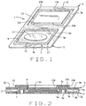
- FIG. 1 is a perspective view of a fragrance sampler of the present invention prior to assembly of the sampler;
- FIG. 2 a cross-sectional view of the sampler when assembled
- FIG. 3 is a schematic drawing of the sampler producing process
- FIG. 4 is a cross-sectional view of an alternative construction of the fragrance sampler
- FIG. 5 is a cross-sectional view of another alternative construction of the fragrance sampler
- FIG. 6 schematic drawing of an alternative process for producing the sample of either FIG. 2 or 4 ;
- FIGS. 7A-C show three alternative constructions of the fragrance sampler which include single walls
- FIGS. 8A-B show two other alternative constructions of the fragrance sampler which include double walls
- FIGS. 9A-D show alternative constructions of the sampler bottom ply, wherein the bottom ply is provided with flow barriers;
- FIG. 10 is a schematic view of an alternative process for manufacturing the sampler
- FIG. 11 is a cross-sectional view of a further embodiment of the sampler which is similar to the sampler of FIG. 5 , but which lacks the interlock feature of the sampler of FIG. 5 ;
- FIG. 12 is a cross-sectional view of yet another embodiment of the sample in which walls on the top and bottom plies are aligned, and thus, the sampler lacks the interlock feature;
- FIG. 13 is a cross-sectional view of the sampler of FIG. 12 , but with the embossed walls in a collapsed condition;
- FIGS. 14 and 15 are cross-sectional view of a sampler similar to the sampler of FIGS. 12 and 13 , but which has a double wall construction, rather than a single wall construction;
- FIG. 16 is a top view of a sampler with an applicator attached to one ply.
- FIG. 17 is a sectional view of the sampler with an applicator attached to one ply of the present invention.
- FIGS. 1 and 2 A first embodiment of a sampler 1 of the present invention is shown in FIGS. 1 and 2 .
- the sampler 1 includes a top ply 3 and a bottom ply 5 , both of which are preferably formed from a foil, a polyester, or a polyethylene laminated structure.
- the plies can alternatively be made of acetate or other paper, foil, and plastic film laminated or non laminated barrier plies.
- a pressure sensitive adhesive can be applied to either the top ply 3 or bottom ply 5 of the sampler.
- the top and bottom plies 3 and 5 each include top and bottom surfaces 3 a , 5 a and 3 b , 5 b , respectively.
- a wall 7 is formed in the bottom ply 5 which extends up from the bottom ply's upper surface 5 a .
- the wall 7 as shown, has an inner surface 7 a , an outer surface 7 b , and a top surface 7 c which define a channel 7 d in the bottom ply bottom surface 5 b .
- the channel 7 d is preferably rectangular in cross-section (but could have other configurations), and the wall 7 defines a “double wall.”
- the wall 7 also defines a well 9 into which a wet fragrance sample 11 can be deposited.
- the fragrance sample 11 can be a sample of a perfume, or a cosmetic creme, lotion, hair color tint, lip stick, powder, or other cosmetic ingredient.
- An opposing wall 13 is formed in the top ply 3 and extends upwardly from the top ply top surface 3 a (with reference to FIG. 2 ).
- the wall 13 has an inner surface 13 a , an outer surface 13 b , and a top surface 13 c which, in combination, define a channel 13 d in the top ply bottom surface 3 b (again, with reference to FIG. 2 ).
- the top ply channel 13 d corresponds in shape to the bottom ply wall 7 .
- the top ply channel 13 d is preferably rectangular in cross-section (but could have other configurations that correspond to the configuration of the bottom ply channel 7 d ), and the wall 13 is a “double wall.”
- the wall 13 in the upper ply has dimensions slightly larger than the dimensions of the bottom ply wall 7
- the channel 13 d is slightly wider than the channel 7 d .
- the top ply wall 13 receives the bottom ply wall 7 , as seen in FIG. 2 , so that the walls 7 a - c defining the lower ply channel 7 d are substantially adjacent the walls 13 a - c defining the upper ply channel 13 d.
- top and bottom ply walls 7 and 13 are preferably formed by an embossing/debossing process.
- the top and bottom plies each include a frame 15 , 17 surrounding the walls 7 and 13 , respectively.
- the top ply 3 and bottom ply 5 are adhered together to cover and close the well 9 so that the sample 11 will be sealed in the well 9 between the two plies.
- the plies can be joined by heat sealing or sonically sealing the two plies together or using an adhesive to bond the top plies together. If an adhesive is used, the adhesive can be cationic cure coating adhesive, or other equally acceptable adhesive which will form a liquid tight barrier to prevent premature release of the fragrance contained in the well 9 .
- the sampler 1 ′ includes a top ply 3 ′ and a bottom ply 5 ′.
- the top and bottom plies 3 ′ and 5 ′ each include top and bottom surfaces 3 a ′, 5 a ′ and 3 b ′, 5 b ′.
- a wall 7 ′ extends up from the bottom ply's upper surface 5 a ′.
- the wall 7 ′ is a single wall.
- the wall 7 ′ is spaced inwardly from the outer edge of the sampler bottom ply 5 ′ and extends around the bottom ply 5 ′ to form a well 9 ′ into which a wet fragrance sample 11 ′ can be deposited.
- An opposing wall 13 ′ extends up from the top ply top surface 3 a ′.
- the wall 13 ′ has an inner surface 13 a ′, an outer surface 13 b ′, and a top surface 13 c ′ which, in combination, define a channel 13 d ′ in the top ply bottom surface 3 b ′.
- the top ply channel 13 d ′ is sized to receive the bottom ply wall 7 ′, so that the walls 7 ′ and 13 ′ are engaged when the sampler 1 ′ is formed.
- the sampler 1 ′′ includes a top ply 3 ′′ and a bottom ply 5 ′′ having upper and lower surfaces 3 a ′′, 5 a ′′ and 3 b ′′, 5 b ′′, respectively.
- the fragrance sampler 1 ′′ includes a well 9 ′′ formed in the bottom ply 5 ′′ which holds the fragrance sample 11 ′′.
- the well 9 ′′ is below the plane of the bottom ply 5 ′′.
- the well 9 ′′ can be formed by either an embossing or debossing process.
- the top ply 3 ′′ includes a wall 13 ′′ which extends from the top ply bottom surface 3 b ′′.
- the wall 13 ′′ is sized to be received in the well 9 ′′ so that, when the sampler 1 ′′ is formed, the wall 13 ′′ will be adjacent the wall 7 ′′ of the well 9 ′′ and so that the two walls will engage each other to form a liquid tight seal to retain the liquid fragrance sample in the well 9 ′′.
- the sampler 1 ′′ includes no “double walls”, rather, both the walls 7 ′′ and 13 ′′ are single walls.
- FIG. 3 The process for producing the samplers 1 , 1 ′, and 1 ′′ is shown schematically in FIG. 3 .
- Webs of the top and bottom ply material are originally contained on rollers 21 and 23 , respectively.
- the top ply material is pulled off the top ply roller 21 and passed through a printer station 25 and then through an embossing station 27 .
- desired graphics are printed on the top surface 3 a , 3 a ′, 3 a ′′ of the top ply 3 , 3 ′, 3 ′′.
- the top ply wall 13 , 13 ′, 13 ′′ is formed at the embossing station 27 .
- the top foil laminated ply is printed on a narrow web flexographic or letter press printing press, with all subsequent finishing steps performed either in-line or off-line.
- the bottom ply material is pulled off the bottom ply roller 23 and passed through an embossing station 29 where the bottom ply wall 7 , 7 ′, 7 ′′ is formed.
- a flat bed embossing tool is used to push up or emboss the wall 7 , 7 ′, 7 ′′ on the bottom ply to form the well 9 , 9 ′, 9 ′′.
- the bottom ply embossing can be also be formed by rotary embossing methods.
- the bottom ply 5 , 5 ′, 5 ′′ is passed under an injection station 31 where a liquid fragrance sample is deposited in the well 9 , 9 ′, 9 ′′.
- the sample 11 , 11 ′, 11 ′′ can be deposited in any other desired manner, such as extrusion, spray, flexographic equipment or silkscreen.
- the top ply is passed about a pair of rollers 33 and 35 to bring the top ply 3 , 3 ′, 3 ′′ into close proximity with the bottom ply 5 , 5 ′, 5 ′′.
- the path of travel of the bottom ply is preferably substantially horizontal, at least after the fragrance sample has been deposited in the bottom ply well 9 , 9 ′, 9 ′′, to avoid spilling of the sample.
- the top ply 3 , 3 ′, 3 ′′ is preferably brought to the bottom ply 5 , 5 ′, 5 ′′.
- the process could be designed so that the bottom ply is brought up to the top ply.
- the two plies are then passed through a sealing station 37 where the two plies are adhered together to form a liquid tight seal which will contain the fragrance sample in the chamber.
- the sealing station interlocks with the well wall 7 , 7 ′, 7 ′′ with the top ply wall 13 , 13 ′, 13 ′′ to form a safe, closed well for the sample material.
- the webs of top ply and bottom ply material move at an indexed rate such that when the two plies are brought together at the sealing station, the top ply wall 13 , 13 ′, 13 ′′ will be in alignment with the bottom ply wall 7 , 7 ′, 7 ′′.
- the sealing station 37 is preferably is a heat sealer, and the top and bottom plies can be adhered or sealed together for example, by welding (such as friction, sonic, or ultrasonic welding), or other standard heat sealing processes which will create a seal between the two plies.
- the sealing station can utilize an adhesive, such as cationic cure coating adhesives, traditional cohesive seals, or adhesive seals, which will bind the top and bottom plies together to form the seal.
- the joined plies are then passed to a die-cut station 39 where side portions of the frames 15 and 17 are removed from the formed samplers.
- the die-cutting step can be performed with either rotary or flat bed equipment.
- the formed samplers are then collected on a product roller 41 .
- Product is delivered in roll form for automatic applications to other printed materials.
- the die-cutting station 39 can also form perforations between adjacent samplers to facilitate separation of the samplers.
- the waste material can be collected on a waste roller 43 .
- a pressure sensitive material with a release liner can be incorporated into the bottom ply so as to result in a product that can later be readily applied to another substrate using affixing equipment.
- the pressure sensitive adhesive with its release liner can be applied to the bottom layer ply.
- the pressure sensitive adhesive can be applied to the bottom ply either as a pre-treatment or after the embossing/debossing process.
- FIG. 6 An alternative production process is shown in FIG. 6 .
- webs of the top and bottom ply material are originally contained on rollers 21 and 23 , respectively.
- the top ply material is pulled off the top ply roller 21 and passed through a printer station 25 where desired graphics are printed on the top surface of the top ply.
- the bottom ply material is pulled off the bottom ply roller 23 under an injection station 31 where a liquid fragrance sample is deposited on the bottom ply.
- the liquid fragrance sample is deposited on the bottom ply prior to the formation of the walls of the top and bottom plies.
- the top ply is passed about a pair of rollers 33 and 35 to bring the top ply into close proximity with the bottom ply.
- the path of travel of the bottom ply is preferably substantially horizontal, at least after the fragrance sample has been deposited on the bottom ply to avoid spilling of the sample.
- the top ply is preferably brought to the bottom ply.
- the process could be designed so that the bottom ply is brought up to the top ply.
- the two plies are then passed through a sealing station 37 . At the sealing station 37 , the walls of the top and bottom plies are formed, and the two plies are adhered together to form a liquid tight seal which will contain the fragrance sample in the chamber.
- the sealing station interlocks with the well wall with the top ply wall to form a safe, closed well for the sample material.
- the webs of top ply and bottom ply material move at an indexed rate such that when the two plies are brought together at the sealing station, the fragrance will be within the walls formed at the sealing station and the printing on the top ply will be above the liquid fragrance sample.
- the sealing station 37 is preferably a heat sealer, which embosses/debosses the top and bottom ply walls in the sampler at the same time the sampler plies are heat sealed together.
- the joined plies are then passed to a die-cut station 39 where side portions of the frames 15 and 17 are removed from the formed samplers.
- the die-cutting step can be performed with either rotary or flat bed equipment.
- the formed samplers are then collected on a product roller 41 .
- Product is delivered in roll form for automatic applications to other printed materials.
- the waste material can be collected on a waste roller 43 .
- the walls in the bottom ply can be “pre-formed” to allow for filling of the well in an off-line operation.
- the sampler of the present invention is easily formed from only two plies of material.
- the top and bottom ply walls are substantially adjacent each other, to engage each other to form a liquid tight seal around the fragrance sample. Additionally, the adjacent walls will reinforce each other to enable the walls to carry the stacking or compression forces to reduce seal failures and fragrance leaks.
- the fragrance sampler 100 has a top ply 103 and a bottom ply 105 .
- the bottom ply 105 is flat. That is, it does not include any walls or wells which define a chamber. Rather, the top ply has a pair of spaced apart walls 113 A and 113 B which are concentric with each other, and which extend downwardly from the bottom surface of the top ply.
- the sampler 100 is formed in substantially the same way as described above, with the fragrance sample being deposited on the bottom ply 105 in an area which will be surrounded by the wall 113 B, so as to be contained within the sampler upon sealing of the sampler.
- the two plies can be reversed, so that the walls 113 A, B form a chamber into which the fragrance sample is deposited during formation of the sampler.
- the well will be formed in the bottom ply, and the top ply will be flat.
- the top ply will then be sealed (such as by heat sealing) to the bottom ply to form a liquid tight seal between the two plies.
- the sampler 100 A shown in FIG. 7B includes the top ply 103 identical to the top ply 103 of the sampler 100 ( FIG. 7A ), and a bottom ply 105 A.
- the bottom ply includes a single wall 107 which extends upwardly from the upper surface of the bottom ply to define a fragrance chamber 109 .
- the bottom ply wall 107 is positioned to be contained within the top ply wall 113 B, and sized so that its outer surface will abut the inner surface of the top ply wall 113 B. Thus, the walls 107 and 113 B will effectively engage each other when the sampler is sealed.
- the sampler 100 B shown in FIG. 7C includes the top ply 103 identical to the top ply 103 of the sampler 100 ( FIG. 7A ), and a bottom ply 105 B.
- the bottom ply 105 B includes a pair of spaced apart walls 107 A and 107 B which are concentric with each other, the wall 107 B being contained within the wall 107 A.
- the top ply walls and bottom ply walls are sized to be off-set from each other, such that the bottom ply wall 107 A is received between the top ply walls 113 A and 113 B; and the bottom ply wall 107 B is received inwardly of the top ply wall 113 B.
- the walls 113 A, B and 107 A, B mesh with each other.
- the samplers 100 , 100 A, and 100 B all include single walls, as opposed to double walls, such as the walls 7 and 13 of the sampler 1 ( FIG. 2 ).
- the samplers 200 and 200 A shown in FIGS. 8A and 8B respectively, include only double walls.
- the sampler 200 ( FIG. 8A ) includes a top ply 203 and a bottom ply 205 .
- the bottom ply 205 is identical to the bottom ply 105 ( FIG. 7A ); it is flat and has no walls, wells, etc.
- the top ply 203 includes a pair of double walls 213 A and 213 B which are concentric with each other, the wall 213 B being formed within the wall 213 A. As seen in FIG.
- the concentric double walls which are adjacent each other, give the top ply a crenelated appearance.
- the sampler 200 is similar to the sampler 100 , except that the single top ply walls 113 A, B of the sampler 100 have been replaced with the double walls 213 A, B.
- the sampler 200 would be formed substantially the same way as the sampler 100 .
- the sampler 200 could be formed such that the walls are formed in the bottom ply to define a well into which the sample is deposited. The top ply would then be flat. After the sample is deposited in the well, the two plies are brought together, as discussed above, to adhere the two plies together to form a liquid tight seal between the two plies.
- the sampler 200 A ( FIG. 8B ) is somewhat similar to the sampler 1 ( FIG. 2 ). It includes a top ply 203 A and a bottom ply 203 B.
- the top ply 203 A includes a double wall 213 which extends downwardly from the top ply's bottom surface.
- the bottom ply includes an upwardly extending wall 207 .
- the wall 7 is received in the channel defined by the wall 13 .
- the respective location of the bottom ply wall has been moved relative to the top ply wall, so that the outer surface of the bottom ply wall 201 is adjacent the inner surface of the top ply wall 213 when the sampler is formed.
- FIGS. 9A-9D show various alternative configurations to the wells 309 A-D in the bottom plies 305 A-D.
- the well 309 A is provided with a bottom surface having dimples 306 A. The dimples are preferably formed in a desired pattern in the bottom of the well 309 A.
- the well 309 B is provided with knurls 306 B in the bottom surface of the well.
- the well 309 C is provided with baffles 306 C in the form of crenellations which extend across the well.
- the well 309 D is provided with triangular grooves or hatches 306 D in the bottom surface of the well.
- the formations 306 A-D in the bottom surface of the well provide barriers to the flow of the wet sample which is deposited in the well.
- the four formations shown are illustrative only, and other types of formations which will impede the flow of a wet sample can also be used.
- the barriers shown in FIGS. 9A-D can be incorporated into any of the samplers discussed above.
- the barriers can be formed in any desired manner, but are preferably formed in the same manner that the top and bottom ply walls are formed.
- FIG. 10 shows a method, somewhat similar to the method of FIG. 6 , for producing the samplers.
- the top and bottom plies are pre-formed—that is, the various walls in the top and bottom plies are formed in a first operation to form a continuous web of sampler top and bottom plies.
- the two webs are formed onto rolls 21 ′ and 23 ′ from which the webs 3 ′ and 5 ′ are pulled.
- the two webs 3 ′ and 5 ′ threaded into the machinery, such that when they are brought together at the sealing station 37 , the two plies will be in register.
- the bottom ply 5 ′ Prior to reaching the sealing station, the bottom ply 5 ′ is brought past the injection station 31 where the sample is injected onto the ply 5 ′.
- the web 5 ′ is threaded into the machinery so that the sample will be deposited in the well of the bottom ply (if the well is preformed).
- the web then passes through the cutting stating 39 where the sealed web is either perforated, or cut, to produce separable (or separated) samplers which can then be inserted in a magazine, mailer, etc.
- the samplers of FIGS. 1-9D all include interlocking walls, as described above.
- the samplers of FIGS. 11-14 do not have interlocking walls.
- the sampler 400 of FIG. 11 is similar to the sampler 1 ′′ of FIG. 5 .
- the sampler 400 includes a top ply 402 and a bottom ply 404 .
- the bottom ply 404 has a well 406 that is formed in the bottom ply by an embossing or debossing procedure.
- the well 406 is below the plane of the bottom ply 404 , and is shown to be generally concave and curved (as opposed to rectangular).
- the top ply 402 includes a wall 408 , which is shown to be a double wall similar to the wall 13 of the sampler 10 ( FIG. 1 ) However, the wall 408 is positioned such that its inner surface is approximately aligned with the periphery of the well 406 . Thus, the bottom surface 408 a of the wall will contact the upper surface of the bottom ply 404 .
- the sampler 400 can be formed using any of the methods described above.
- the sample will be received in the well 406 , and, in a subsequent step, the wall bottom surface 408 a will sealed to the bottom ply top surface to form a liquid tight seal around the well.
- the seal between the wall bottom surface and the bottom ply top surface can be formed in any number of ways. For example the seal can be formed by welding (such as heat welding, sonic welding, ultrasonic welding, friction welding, etc.) or by bonding using adhesives.
- the sampler 500 of FIG. 12 includes bottom and top plies 502 and 504 .
- Walls 506 and 508 are formed on the bottom and top plies, respectively, such that the walls face each other.
- the bottom ply wall 506 is formed on the upper surface of the bottom ply and the top ply wall 508 is formed on the bottom surface of the top ply.
- the walls 506 and 508 are shown to be double walls, but could be single walls if desired. As can be seen, the walls 506 and 508 are aligned with each other, such that their respective end surfaces 506 a and 508 a will contact each other when the two plies are brought together.
- the sampler 500 lacks the interlocking feature of the sampler 10 ( FIG. 1 ), for example.
- the two plies are joined together at the walls to form a liquid tight seal between the top and bottom plies.
- the seal between the wall bottom surface and the bottom ply top surface can be formed in any number of ways.
- the seal can be formed by welding (such as heat welding, sonic welding, ultrasonic welding, friction welding, etc.) or by bonding using adhesives.
- the use of double walls facilitates welding of the two plies together.
- the top and bottom ply walls 506 and 508 are crushed together, as seen in FIG. 13 . When collapsed, the walls do not return to their original flat surface configuration. Rather, they form a physical wall barrier that provides additional compression resistance to the finished product.
- the sampler 600 shown in FIGS. 14 and 15 is substantially similar to the sampler 500 .
- the sampler 600 is provided with two walls 606 and 607 on the bottom ply 602 and two wall 608 and 609 on the top ply 604 .
- the walls 607 and 609 are outer walls which surround walls 606 and 608 , which are inner walls.
- the walls of the sampler are aligned with each other.
- the wall 606 and 608 are aligned and the walls 607 and 609 are aligned.
- the top and bottom plies 602 and 604 are assembled together in the same manner as the plies of the sampler 500 , and, upon assembly, the walls 606 - 609 are crushed or collapsed, as seen in FIG. 15 .
- FIGS. 16 and 17 Another embodiment of a sampler 700 of the present invention is shown in FIGS. 16 and 17 .
- the sampler 700 has similarities with the sampler 1 .
- the sampler 700 includes a top ply 703 and a bottom ply 705 , that each include top and bottom surfaces 703 a , 705 a and 703 b , 705 b , respectively.
- a wall 707 is formed in the bottom ply 705 upwardly from the upper surface 705 a .
- the wall 707 as shown, has an inner surface 707 a , an outer surface 707 b , and a top surface 707 c which define a channel 707 d in the bottom surface 705 b .
- the channel 707 d has a rectangular cross-section with radiused, or curved corners.
- the wall 707 along three or more edges of the sampler 700 defines a well 709 into which a wet fragrance sample 11 can be deposited, such as a perfume, a cosmetic creme, lotion, hair color tint, lip stick, powder, or other cosmetic ingredient.
- the bottom ply 705 can incorporate a pressure sensitive construction rendering the sampler 700 in label form for affixing onto mailing cards or magazine inserts.
- the top ply 703 engages the wall 707 and corresponds in shape to the bottom ply 705 .
- a channel 713 forms in the top ply 703 which extends below the top surface 703 a .
- the channel 713 has a top surface 713 a , an inner surface 713 b perpendicular to the top surface 713 a , and a base surface 713 c parallel and offset beneath the top surface 713 a .
- the channel 713 has a generally rectangular symmetric cross section as in FIG. 17 on the left.
- the base surface 713 c has an attached applicator 714 .
- the applicator 714 has less height than the combined inner surfaces 713 b , 707 a and a width and a length to fit within the channel 713 and well 709 .
- the applicator 714 has a construction of cellulose, organic, or similar non-woven fabric type material.
- the applicator 714 absorbs water, alcohol, oil, and the like based cosmetics.
- the channel 713 in the upper ply 703 has dimensions slightly larger than the dimensions of the wall 707 , and the channel 713 is slightly wider and longer than the well 709 .
- the base surface 713 c has a width and a length to receive the wall 707 from the bottom ply 705 much like a cap.
- the surfaces 707 a, b, c defining the lower ply channel 707 d are substantially adjacent to the surfaces 713 a, b, c defining the upper ply channel 713 .
- the top and bottom plies 703 , 705 each include a frame 715 , 717 surrounding the channel 713 and wall 707 , respectively.
- the top ply 703 and bottom ply 705 are adhered together upon frames 715 , 717 to cover and close the well 709 so that the sample 11 and applicator 714 will be sealed in the well 709 between the two plies 703 , 705 .
- the plies can be joined together by heat sealing or sonic sealing or by an adhesive bond.
- the adhesive can be cationic cure coating adhesive, or other equally acceptable adhesive which will form a liquid tight barrier to prevent premature release of the fragrance sample 11 contained in the well 709 .
- the top ply channel 713 and bottom ply wall 707 are preferably formed by an embossing/debossing process. And, the applicator 714 permanently attaches to the channel 713 of the top ply 703 by adhesives, welding, fusing, or other means.
- the bottom ply can incorporate a pressure sensitive construction rendering the sampler as a label for ease of affixing onto many cards or magazine inserts.
Landscapes
- Health & Medical Sciences (AREA)
- Life Sciences & Earth Sciences (AREA)
- Animal Behavior & Ethology (AREA)
- General Health & Medical Sciences (AREA)
- Public Health (AREA)
- Veterinary Medicine (AREA)
- Engineering & Computer Science (AREA)
- Mechanical Engineering (AREA)
- Epidemiology (AREA)
- Birds (AREA)
- Sampling And Sample Adjustment (AREA)
Abstract
Description
Claims (1)
Priority Applications (2)
| Application Number | Priority Date | Filing Date | Title |
|---|---|---|---|
| US10/986,123 US10874192B2 (en) | 2000-03-20 | 2004-11-10 | Fragrance sampler insert |
| US14/756,635 US20160100670A1 (en) | 2000-03-20 | 2015-09-28 | Dry peel cosmetic sampler |
Applications Claiming Priority (5)
| Application Number | Priority Date | Filing Date | Title |
|---|---|---|---|
| US09/531,296 US6251408B1 (en) | 2000-03-20 | 2000-03-20 | Fragrance sampler insert |
| US09/858,566 US6461620B2 (en) | 2000-03-20 | 2001-05-17 | Fragrance sampler insert |
| US10/233,136 US8003116B2 (en) | 2000-03-20 | 2002-08-30 | Fragrance sampler insert |
| US10/464,392 US20030213724A1 (en) | 2000-03-20 | 2003-06-17 | Fragrance sampler insert |
| US10/986,123 US10874192B2 (en) | 2000-03-20 | 2004-11-10 | Fragrance sampler insert |
Related Parent Applications (1)
| Application Number | Title | Priority Date | Filing Date |
|---|---|---|---|
| US10/464,392 Continuation-In-Part US20030213724A1 (en) | 2000-03-20 | 2003-06-17 | Fragrance sampler insert |
Publications (2)
| Publication Number | Publication Date |
|---|---|
| US20050061710A1 US20050061710A1 (en) | 2005-03-24 |
| US10874192B2 true US10874192B2 (en) | 2020-12-29 |
Family
ID=43706265
Family Applications (1)
| Application Number | Title | Priority Date | Filing Date |
|---|---|---|---|
| US10/986,123 Expired - Fee Related US10874192B2 (en) | 2000-03-20 | 2004-11-10 | Fragrance sampler insert |
Country Status (1)
| Country | Link |
|---|---|
| US (1) | US10874192B2 (en) |
Families Citing this family (10)
| Publication number | Priority date | Publication date | Assignee | Title |
|---|---|---|---|---|
| US20030213724A1 (en) * | 2000-03-20 | 2003-11-20 | Sven Dobler | Fragrance sampler insert |
| USD580593S1 (en) * | 2007-09-24 | 2008-11-11 | Mcneil-Ppc, Inc. | Fragrance emitting patch |
| US20100108778A1 (en) * | 2008-10-30 | 2010-05-06 | Greenland Steven J | Device for containing and releasing a volatile substance |
| DK2352639T3 (en) | 2008-12-31 | 2013-04-22 | Aki Inc | Device for storing and releasing a sample material |
| WO2011025691A1 (en) * | 2009-08-24 | 2011-03-03 | Aki, Inc. | Unitized package and method of making same |
| US9272830B2 (en) | 2009-08-24 | 2016-03-01 | Aki, Inc. | Unitized package of card and fluid vessel |
| USD651351S1 (en) | 2010-12-30 | 2011-12-27 | Mary Kay Inc. | Cosmetic container |
| FR2976924B1 (en) | 2011-06-27 | 2013-08-02 | Socoplan | SAMPLE SAMPLE OF FLUID PRODUCT. |
| US11319136B2 (en) * | 2020-06-17 | 2022-05-03 | Elc Management Llc | Packaging for sprayable perfume products |
| US12404073B2 (en) * | 2022-06-28 | 2025-09-02 | Barry Davis | Scent indicators on containers |
Citations (42)
| Publication number | Priority date | Publication date | Assignee | Title |
|---|---|---|---|---|
| US4155500A (en) | 1978-05-01 | 1979-05-22 | Champion International Corporation | Diffuser carton |
| US4208012A (en) | 1978-06-09 | 1980-06-17 | Champion International Corporation | Air freshener carton |
| US4279373A (en) | 1979-12-28 | 1981-07-21 | Champion International Corporation | Air freshener carton |
| US4280649A (en) | 1979-12-28 | 1981-07-28 | Champion International Corporation | Air freshener carton |
| US4301095A (en) | 1980-08-18 | 1981-11-17 | Product Enterprise, Inc. | Air freshener dispenser |
| US4484768A (en) | 1983-09-30 | 1984-11-27 | Norfleet Lincoln H | Greeting card |
| US4487801A (en) | 1983-10-11 | 1984-12-11 | Minnesota Mining And Manufacturing Company | Fragrance-releasing pull-apart sheet |
| US4493869A (en) | 1983-10-11 | 1985-01-15 | Minnesota Mining And Manufacturing Company | Fragrance-releasing microcapsules on a see-through substrate |
| US4606956A (en) | 1984-12-21 | 1986-08-19 | Minnesota Mining And Manufacturing Company | On page fragrance sampling device |
| US4615486A (en) | 1984-09-27 | 1986-10-07 | S. C. Johnson & Son, Inc. | Automatic door-activated air freshener |
| US4619383A (en) | 1984-09-27 | 1986-10-28 | S. C. Johnson & Son, Inc. | Automatic door-activated air freshener |
| US4661388A (en) | 1985-01-24 | 1987-04-28 | Minnesota Mining And Manufacturing Company | Pad fragrance sampling device |
| US4720423A (en) | 1986-08-25 | 1988-01-19 | Minnesota Mining And Manufacturing Company | Package opening system |
| US4751934A (en) | 1986-06-17 | 1988-06-21 | Alford Industries, Inc. | Cosmetic sampler |
| US4769264A (en) | 1987-07-15 | 1988-09-06 | Minnesota Mining And Manufacturing Company | On page fragrance sampling device |
| US4809912A (en) | 1987-03-27 | 1989-03-07 | Delaire, Inc. | Membrane-gel diffusion device |
| US4848378A (en) | 1986-06-17 | 1989-07-18 | Alford Industries Inc. | Cosmetic sampler |
| US4858831A (en) | 1988-02-22 | 1989-08-22 | Donald Spector | Hand-actuated fragrance emitting unit |
| US4869407A (en) | 1988-04-15 | 1989-09-26 | Products By Designair, Inc. | Air-freshener apparatus |
| US4880690A (en) | 1984-11-13 | 1989-11-14 | Thermedics, Inc. | Perfume patch |
| US5031647A (en) * | 1989-11-03 | 1991-07-16 | David Seidler | Cosmetic sampler applicator |
| US5093182A (en) | 1990-09-17 | 1992-03-03 | Arcade, Inc. | Sustained-release, print-compatible coatings for fragrance samplers |
| US5161688A (en) | 1988-04-22 | 1992-11-10 | Muchin Jerome D | Sampler and method of making the same |
| US5192386A (en) | 1986-06-17 | 1993-03-09 | Alford Industries Inc. | Method of making a cosmetic sampler |
| US5192380A (en) | 1989-12-19 | 1993-03-09 | The Yokohama Rubber Co., Ltd. | Pneumatic radial tire for passenger vehicle including a particular carcass line |
| US5249676A (en) | 1991-05-07 | 1993-10-05 | R. J. Reynolds Tobacco Company | Flavor burst structure and method of making the same |
| US5348031A (en) * | 1993-09-20 | 1994-09-20 | Cloud Linda D | Cosmetic apparatus |
| US5391420A (en) * | 1991-07-16 | 1995-02-21 | Thermedics Inc. | Fragrance-laden pouch samplers and process for their manufacture |
| US5566693A (en) | 1986-06-17 | 1996-10-22 | Color Prelude, Inc. | Fragrance sampler |
| US5622263A (en) * | 1995-05-01 | 1997-04-22 | Webcraft Technologies, Inc. | Sampler package and method of making the same |
| US5645161A (en) | 1996-01-22 | 1997-07-08 | Orlandi Inc. | Fragrance packet sampler |
| US5690130A (en) | 1986-06-17 | 1997-11-25 | Color Prelude Inc. | Cosmetic sampler with integral applicator |
| US5845847A (en) | 1996-05-14 | 1998-12-08 | S. C. Johnson & Son, Inc. | Air freshener dispenser device |
| US5879769A (en) | 1996-09-12 | 1999-03-09 | Arcade, Inc. | Sampler device having a reinforced compartment and method of packaging sample material |
| US5899382A (en) | 1996-05-24 | 1999-05-04 | Woodco Manufacturing, Inc. | Air freshener |
| US6006916A (en) * | 1998-06-12 | 1999-12-28 | Color Prelude, Inc. | Cosmetic sampler with applicator backing |
| US6012643A (en) | 1995-12-05 | 2000-01-11 | S.C. Johnson & Son, Inc. | Dispensing device |
| US6251408B1 (en) * | 2000-03-20 | 2001-06-26 | Orlandi, Inc. | Fragrance sampler insert |
| US6305531B1 (en) | 1999-05-25 | 2001-10-23 | Michael A. Wilkman | Reduced cost impregnated wipes |
| US6461620B2 (en) * | 2000-03-20 | 2002-10-08 | Orlandi, Inc. | Fragrance sampler insert |
| US20030010670A1 (en) | 2000-03-20 | 2003-01-16 | Sven Dobler | Fragrance sampler insert |
| US20030106812A1 (en) | 2001-09-19 | 2003-06-12 | Wilkman Michael A. | Impregnated wipe package with features improving handling and reducing transdermal migration |
Family Cites Families (2)
| Publication number | Priority date | Publication date | Assignee | Title |
|---|---|---|---|---|
| US4615786A (en) * | 1985-04-18 | 1986-10-07 | Dorr-Oliver Incorporated | Non ion selective membrane in an EAVF system |
| US5429420A (en) * | 1994-01-03 | 1995-07-04 | Norton Company | Pavement cutting saw |
-
2004
- 2004-11-10 US US10/986,123 patent/US10874192B2/en not_active Expired - Fee Related
Patent Citations (44)
| Publication number | Priority date | Publication date | Assignee | Title |
|---|---|---|---|---|
| US4155500A (en) | 1978-05-01 | 1979-05-22 | Champion International Corporation | Diffuser carton |
| US4208012A (en) | 1978-06-09 | 1980-06-17 | Champion International Corporation | Air freshener carton |
| US4279373A (en) | 1979-12-28 | 1981-07-21 | Champion International Corporation | Air freshener carton |
| US4280649A (en) | 1979-12-28 | 1981-07-28 | Champion International Corporation | Air freshener carton |
| US4301095A (en) | 1980-08-18 | 1981-11-17 | Product Enterprise, Inc. | Air freshener dispenser |
| US4484768A (en) | 1983-09-30 | 1984-11-27 | Norfleet Lincoln H | Greeting card |
| US4487801A (en) | 1983-10-11 | 1984-12-11 | Minnesota Mining And Manufacturing Company | Fragrance-releasing pull-apart sheet |
| US4493869A (en) | 1983-10-11 | 1985-01-15 | Minnesota Mining And Manufacturing Company | Fragrance-releasing microcapsules on a see-through substrate |
| US4615486A (en) | 1984-09-27 | 1986-10-07 | S. C. Johnson & Son, Inc. | Automatic door-activated air freshener |
| US4619383A (en) | 1984-09-27 | 1986-10-28 | S. C. Johnson & Son, Inc. | Automatic door-activated air freshener |
| US4880690A (en) | 1984-11-13 | 1989-11-14 | Thermedics, Inc. | Perfume patch |
| US4606956A (en) | 1984-12-21 | 1986-08-19 | Minnesota Mining And Manufacturing Company | On page fragrance sampling device |
| US4661388A (en) | 1985-01-24 | 1987-04-28 | Minnesota Mining And Manufacturing Company | Pad fragrance sampling device |
| US5562112A (en) | 1986-06-17 | 1996-10-08 | Color Prelude, Inc. | Lipstick sampler |
| US4751934A (en) | 1986-06-17 | 1988-06-21 | Alford Industries, Inc. | Cosmetic sampler |
| US5192386A (en) | 1986-06-17 | 1993-03-09 | Alford Industries Inc. | Method of making a cosmetic sampler |
| US4848378A (en) | 1986-06-17 | 1989-07-18 | Alford Industries Inc. | Cosmetic sampler |
| US5566693A (en) | 1986-06-17 | 1996-10-22 | Color Prelude, Inc. | Fragrance sampler |
| US5690130A (en) | 1986-06-17 | 1997-11-25 | Color Prelude Inc. | Cosmetic sampler with integral applicator |
| US4720423A (en) | 1986-08-25 | 1988-01-19 | Minnesota Mining And Manufacturing Company | Package opening system |
| US4809912A (en) | 1987-03-27 | 1989-03-07 | Delaire, Inc. | Membrane-gel diffusion device |
| US4769264A (en) | 1987-07-15 | 1988-09-06 | Minnesota Mining And Manufacturing Company | On page fragrance sampling device |
| US4858831A (en) | 1988-02-22 | 1989-08-22 | Donald Spector | Hand-actuated fragrance emitting unit |
| US4869407A (en) | 1988-04-15 | 1989-09-26 | Products By Designair, Inc. | Air-freshener apparatus |
| US5161688A (en) | 1988-04-22 | 1992-11-10 | Muchin Jerome D | Sampler and method of making the same |
| US5031647A (en) * | 1989-11-03 | 1991-07-16 | David Seidler | Cosmetic sampler applicator |
| US5192380A (en) | 1989-12-19 | 1993-03-09 | The Yokohama Rubber Co., Ltd. | Pneumatic radial tire for passenger vehicle including a particular carcass line |
| US5093182A (en) | 1990-09-17 | 1992-03-03 | Arcade, Inc. | Sustained-release, print-compatible coatings for fragrance samplers |
| US5249676A (en) | 1991-05-07 | 1993-10-05 | R. J. Reynolds Tobacco Company | Flavor burst structure and method of making the same |
| US5391420A (en) * | 1991-07-16 | 1995-02-21 | Thermedics Inc. | Fragrance-laden pouch samplers and process for their manufacture |
| US5348031A (en) * | 1993-09-20 | 1994-09-20 | Cloud Linda D | Cosmetic apparatus |
| US5622263A (en) * | 1995-05-01 | 1997-04-22 | Webcraft Technologies, Inc. | Sampler package and method of making the same |
| US6012643A (en) | 1995-12-05 | 2000-01-11 | S.C. Johnson & Son, Inc. | Dispensing device |
| US5645161A (en) | 1996-01-22 | 1997-07-08 | Orlandi Inc. | Fragrance packet sampler |
| US5845847A (en) | 1996-05-14 | 1998-12-08 | S. C. Johnson & Son, Inc. | Air freshener dispenser device |
| US5899382A (en) | 1996-05-24 | 1999-05-04 | Woodco Manufacturing, Inc. | Air freshener |
| US5879769A (en) | 1996-09-12 | 1999-03-09 | Arcade, Inc. | Sampler device having a reinforced compartment and method of packaging sample material |
| US6006916A (en) * | 1998-06-12 | 1999-12-28 | Color Prelude, Inc. | Cosmetic sampler with applicator backing |
| US6305531B1 (en) | 1999-05-25 | 2001-10-23 | Michael A. Wilkman | Reduced cost impregnated wipes |
| US20020011424A1 (en) | 1999-05-25 | 2002-01-31 | Wilkman Michael A. | Reduced cost impregnated wipes |
| US6251408B1 (en) * | 2000-03-20 | 2001-06-26 | Orlandi, Inc. | Fragrance sampler insert |
| US6461620B2 (en) * | 2000-03-20 | 2002-10-08 | Orlandi, Inc. | Fragrance sampler insert |
| US20030010670A1 (en) | 2000-03-20 | 2003-01-16 | Sven Dobler | Fragrance sampler insert |
| US20030106812A1 (en) | 2001-09-19 | 2003-06-12 | Wilkman Michael A. | Impregnated wipe package with features improving handling and reducing transdermal migration |
Also Published As
| Publication number | Publication date |
|---|---|
| US20050061710A1 (en) | 2005-03-24 |
Similar Documents
| Publication | Publication Date | Title |
|---|---|---|
| US9399081B2 (en) | Fragrance sampler insert | |
| US6461620B2 (en) | Fragrance sampler insert | |
| US6251408B1 (en) | Fragrance sampler insert | |
| US10874192B2 (en) | Fragrance sampler insert | |
| US20170000238A1 (en) | Cosmetic Products Application | |
| AU713696B2 (en) | Sampler device having a reinforced compartment and method of packaging sample material | |
| US20100326462A1 (en) | Cosmetic products applicator | |
| EP0722676B1 (en) | Cosmetic sampler with integral applicator | |
| US8003116B2 (en) | Fragrance sampler insert | |
| TWI555519B (en) | The packaging of absorbent articles | |
| EP1310186B1 (en) | Cosmetic articles having encapsulated liquid and method of making same | |
| AU596164B2 (en) | Lamination anchoring method and product thereof | |
| US5445821A (en) | Fragrance sampler and applicator with simulated container and removable cap | |
| US4529125A (en) | Device for dispensing of volatile substance and method for making the device | |
| WO2010078286A1 (en) | Device for containing and releasing a sample material | |
| DE69307922T2 (en) | APPLICATION UNITS FOR VOLATILE LIQUIDS AND METHOD FOR THE PRODUCTION THEREOF | |
| US6686013B1 (en) | Article comprising board, paper or the like and process and intermediate product for the production thereof | |
| DE60127255T2 (en) | EXTREMELY FLAT HOUSING FOR ADVERTISING | |
| US20150140054A1 (en) | Scent/fragrance sampling card and method of manufacture | |
| US20160100670A1 (en) | Dry peel cosmetic sampler | |
| US4529124A (en) | Device for dispensing of volatile substance and method for making the device | |
| US20080241453A1 (en) | Fragrance advertising assembly | |
| EP0970674A2 (en) | A make up removal pad | |
| US20210362932A1 (en) | Sampler for cosmetic or fragrance powdery material and method | |
| DE2109416A1 (en) | Process for the production of litter containers with a predetermined opening and litter container |
Legal Events
| Date | Code | Title | Description |
|---|---|---|---|
| STCV | Information on status: appeal procedure |
Free format text: ON APPEAL -- AWAITING DECISION BY THE BOARD OF APPEALS |
|
| STCV | Information on status: appeal procedure |
Free format text: BOARD OF APPEALS DECISION RENDERED |
|
| STPP | Information on status: patent application and granting procedure in general |
Free format text: NOTICE OF ALLOWANCE MAILED -- APPLICATION RECEIVED IN OFFICE OF PUBLICATIONS |
|
| ZAAA | Notice of allowance and fees due |
Free format text: ORIGINAL CODE: NOA |
|
| ZAAB | Notice of allowance mailed |
Free format text: ORIGINAL CODE: MN/=. |
|
| STPP | Information on status: patent application and granting procedure in general |
Free format text: AWAITING TC RESP., ISSUE FEE NOT PAID |
|
| STPP | Information on status: patent application and granting procedure in general |
Free format text: NOTICE OF ALLOWANCE MAILED -- APPLICATION RECEIVED IN OFFICE OF PUBLICATIONS |
|
| STPP | Information on status: patent application and granting procedure in general |
Free format text: NOTICE OF ALLOWANCE MAILED -- APPLICATION RECEIVED IN OFFICE OF PUBLICATIONS |
|
| STPP | Information on status: patent application and granting procedure in general |
Free format text: PUBLICATIONS -- ISSUE FEE PAYMENT VERIFIED |
|
| STCF | Information on status: patent grant |
Free format text: PATENTED CASE |
|
| AS | Assignment |
Owner name: ORLANDI, INC., NEW YORK Free format text: ASSIGNMENT OF ASSIGNORS INTEREST;ASSIGNOR:DOBLER, SVEN;REEL/FRAME:054783/0445 Effective date: 20201228 |
|
| FEPP | Fee payment procedure |
Free format text: MAINTENANCE FEE REMINDER MAILED (ORIGINAL EVENT CODE: REM.); ENTITY STATUS OF PATENT OWNER: SMALL ENTITY |
|
| LAPS | Lapse for failure to pay maintenance fees |
Free format text: PATENT EXPIRED FOR FAILURE TO PAY MAINTENANCE FEES (ORIGINAL EVENT CODE: EXP.); ENTITY STATUS OF PATENT OWNER: SMALL ENTITY |
|
| STCH | Information on status: patent discontinuation |
Free format text: PATENT EXPIRED DUE TO NONPAYMENT OF MAINTENANCE FEES UNDER 37 CFR 1.362 |
|
| FP | Lapsed due to failure to pay maintenance fee |
Effective date: 20241229 |