US10866499B2 - Retroreflective sheeting for projector-based display system - Google Patents
Retroreflective sheeting for projector-based display system Download PDFInfo
- Publication number
- US10866499B2 US10866499B2 US16/560,453 US201916560453A US10866499B2 US 10866499 B2 US10866499 B2 US 10866499B2 US 201916560453 A US201916560453 A US 201916560453A US 10866499 B2 US10866499 B2 US 10866499B2
- Authority
- US
- United States
- Prior art keywords
- degrees
- retroreflective
- grooves
- angle
- less
- Prior art date
- Legal status (The legal status is an assumption and is not a legal conclusion. Google has not performed a legal analysis and makes no representation as to the accuracy of the status listed.)
- Active
Links
- 238000009792 diffusion process Methods 0.000 claims description 51
- 238000000034 method Methods 0.000 claims description 16
- 210000000887 face Anatomy 0.000 description 23
- 239000002245 particle Substances 0.000 description 17
- 238000005520 cutting process Methods 0.000 description 11
- NIXOWILDQLNWCW-UHFFFAOYSA-N acrylic acid group Chemical group C(C=C)(=O)O NIXOWILDQLNWCW-UHFFFAOYSA-N 0.000 description 10
- 229920000515 polycarbonate Polymers 0.000 description 10
- 239000004417 polycarbonate Substances 0.000 description 10
- 239000000758 substrate Substances 0.000 description 9
- 239000010410 layer Substances 0.000 description 8
- 239000000463 material Substances 0.000 description 7
- 230000008901 benefit Effects 0.000 description 6
- VYPSYNLAJGMNEJ-UHFFFAOYSA-N Silicium dioxide Chemical compound O=[Si]=O VYPSYNLAJGMNEJ-UHFFFAOYSA-N 0.000 description 5
- 238000013461 design Methods 0.000 description 5
- 230000003287 optical effect Effects 0.000 description 5
- VTYYLEPIZMXCLO-UHFFFAOYSA-L Calcium carbonate Chemical compound [Ca+2].[O-]C([O-])=O VTYYLEPIZMXCLO-UHFFFAOYSA-L 0.000 description 4
- 239000012790 adhesive layer Substances 0.000 description 4
- 238000003860 storage Methods 0.000 description 4
- -1 but not limited to Polymers 0.000 description 3
- 230000007423 decrease Effects 0.000 description 3
- 230000006870 function Effects 0.000 description 3
- 229920000642 polymer Polymers 0.000 description 3
- 230000004075 alteration Effects 0.000 description 2
- 230000009286 beneficial effect Effects 0.000 description 2
- 229910000019 calcium carbonate Inorganic materials 0.000 description 2
- 230000000694 effects Effects 0.000 description 2
- 239000004973 liquid crystal related substance Substances 0.000 description 2
- 239000011159 matrix material Substances 0.000 description 2
- 230000015654 memory Effects 0.000 description 2
- 230000004048 modification Effects 0.000 description 2
- 238000012986 modification Methods 0.000 description 2
- 229920003023 plastic Polymers 0.000 description 2
- 229920001343 polytetrafluoroethylene Polymers 0.000 description 2
- 239000004810 polytetrafluoroethylene Substances 0.000 description 2
- 239000000377 silicon dioxide Substances 0.000 description 2
- 235000012239 silicon dioxide Nutrition 0.000 description 2
- 230000007704 transition Effects 0.000 description 2
- 239000004593 Epoxy Substances 0.000 description 1
- JOYRKODLDBILNP-UHFFFAOYSA-N Ethyl urethane Chemical compound CCOC(N)=O JOYRKODLDBILNP-UHFFFAOYSA-N 0.000 description 1
- 239000004793 Polystyrene Substances 0.000 description 1
- XUIMIQQOPSSXEZ-UHFFFAOYSA-N Silicon Chemical compound [Si] XUIMIQQOPSSXEZ-UHFFFAOYSA-N 0.000 description 1
- GWEVSGVZZGPLCZ-UHFFFAOYSA-N Titan oxide Chemical compound O=[Ti]=O GWEVSGVZZGPLCZ-UHFFFAOYSA-N 0.000 description 1
- 230000001594 aberrant effect Effects 0.000 description 1
- 150000001252 acrylic acid derivatives Chemical class 0.000 description 1
- 125000005396 acrylic acid ester group Chemical group 0.000 description 1
- 229920006397 acrylic thermoplastic Polymers 0.000 description 1
- 238000004458 analytical method Methods 0.000 description 1
- 238000013459 approach Methods 0.000 description 1
- 238000003491 array Methods 0.000 description 1
- TZCXTZWJZNENPQ-UHFFFAOYSA-L barium sulfate Chemical compound [Ba+2].[O-]S([O-])(=O)=O TZCXTZWJZNENPQ-UHFFFAOYSA-L 0.000 description 1
- 239000011324 bead Substances 0.000 description 1
- 229920002678 cellulose Polymers 0.000 description 1
- 230000008859 change Effects 0.000 description 1
- 239000003086 colorant Substances 0.000 description 1
- 238000010276 construction Methods 0.000 description 1
- 239000002537 cosmetic Substances 0.000 description 1
- 230000003247 decreasing effect Effects 0.000 description 1
- 230000007547 defect Effects 0.000 description 1
- 230000003292 diminished effect Effects 0.000 description 1
- 239000011521 glass Substances 0.000 description 1
- 210000003128 head Anatomy 0.000 description 1
- 238000005286 illumination Methods 0.000 description 1
- 238000007373 indentation Methods 0.000 description 1
- 150000002484 inorganic compounds Chemical class 0.000 description 1
- 229910010272 inorganic material Inorganic materials 0.000 description 1
- 238000004519 manufacturing process Methods 0.000 description 1
- 229910052751 metal Inorganic materials 0.000 description 1
- 239000002184 metal Substances 0.000 description 1
- 239000000203 mixture Substances 0.000 description 1
- 150000002826 nitrites Chemical class 0.000 description 1
- 239000011022 opal Substances 0.000 description 1
- 150000002894 organic compounds Chemical class 0.000 description 1
- 229920003229 poly(methyl methacrylate) Polymers 0.000 description 1
- 229920002285 poly(styrene-co-acrylonitrile) Polymers 0.000 description 1
- 229920001230 polyarylate Polymers 0.000 description 1
- 229920000728 polyester Polymers 0.000 description 1
- 229920002223 polystyrene Polymers 0.000 description 1
- 230000008569 process Effects 0.000 description 1
- 239000010453 quartz Substances 0.000 description 1
- 230000009467 reduction Effects 0.000 description 1
- 239000012508 resin bead Substances 0.000 description 1
- 239000004065 semiconductor Substances 0.000 description 1
- 229910052710 silicon Inorganic materials 0.000 description 1
- 239000010703 silicon Substances 0.000 description 1
- 229920002050 silicone resin Polymers 0.000 description 1
- ISXSCDLOGDJUNJ-UHFFFAOYSA-N tert-butyl prop-2-enoate Chemical compound CC(C)(C)OC(=O)C=C ISXSCDLOGDJUNJ-UHFFFAOYSA-N 0.000 description 1
- 230000000007 visual effect Effects 0.000 description 1
Images


Classifications
-
- G—PHYSICS
- G03—PHOTOGRAPHY; CINEMATOGRAPHY; ANALOGOUS TECHNIQUES USING WAVES OTHER THAN OPTICAL WAVES; ELECTROGRAPHY; HOLOGRAPHY
- G03B—APPARATUS OR ARRANGEMENTS FOR TAKING PHOTOGRAPHS OR FOR PROJECTING OR VIEWING THEM; APPARATUS OR ARRANGEMENTS EMPLOYING ANALOGOUS TECHNIQUES USING WAVES OTHER THAN OPTICAL WAVES; ACCESSORIES THEREFOR
- G03B21/00—Projectors or projection-type viewers; Accessories therefor
- G03B21/54—Accessories
- G03B21/56—Projection screens
- G03B21/60—Projection screens characterised by the nature of the surface
-
- G—PHYSICS
- G02—OPTICS
- G02B—OPTICAL ELEMENTS, SYSTEMS OR APPARATUS
- G02B5/00—Optical elements other than lenses
- G02B5/12—Reflex reflectors
- G02B5/122—Reflex reflectors cube corner, trihedral or triple reflector type
- G02B5/124—Reflex reflectors cube corner, trihedral or triple reflector type plural reflecting elements forming part of a unitary plate or sheet
-
- G—PHYSICS
- G03—PHOTOGRAPHY; CINEMATOGRAPHY; ANALOGOUS TECHNIQUES USING WAVES OTHER THAN OPTICAL WAVES; ELECTROGRAPHY; HOLOGRAPHY
- G03B—APPARATUS OR ARRANGEMENTS FOR TAKING PHOTOGRAPHS OR FOR PROJECTING OR VIEWING THEM; APPARATUS OR ARRANGEMENTS EMPLOYING ANALOGOUS TECHNIQUES USING WAVES OTHER THAN OPTICAL WAVES; ACCESSORIES THEREFOR
- G03B21/00—Projectors or projection-type viewers; Accessories therefor
- G03B21/10—Projectors with built-in or built-on screen
-
- G—PHYSICS
- G03—PHOTOGRAPHY; CINEMATOGRAPHY; ANALOGOUS TECHNIQUES USING WAVES OTHER THAN OPTICAL WAVES; ELECTROGRAPHY; HOLOGRAPHY
- G03B—APPARATUS OR ARRANGEMENTS FOR TAKING PHOTOGRAPHS OR FOR PROJECTING OR VIEWING THEM; APPARATUS OR ARRANGEMENTS EMPLOYING ANALOGOUS TECHNIQUES USING WAVES OTHER THAN OPTICAL WAVES; ACCESSORIES THEREFOR
- G03B21/00—Projectors or projection-type viewers; Accessories therefor
- G03B21/54—Accessories
- G03B21/56—Projection screens
- G03B21/58—Projection screens collapsible, e.g. foldable; of variable area
-
- G—PHYSICS
- G03—PHOTOGRAPHY; CINEMATOGRAPHY; ANALOGOUS TECHNIQUES USING WAVES OTHER THAN OPTICAL WAVES; ELECTROGRAPHY; HOLOGRAPHY
- G03B—APPARATUS OR ARRANGEMENTS FOR TAKING PHOTOGRAPHS OR FOR PROJECTING OR VIEWING THEM; APPARATUS OR ARRANGEMENTS EMPLOYING ANALOGOUS TECHNIQUES USING WAVES OTHER THAN OPTICAL WAVES; ACCESSORIES THEREFOR
- G03B21/00—Projectors or projection-type viewers; Accessories therefor
- G03B21/54—Accessories
- G03B21/56—Projection screens
- G03B21/60—Projection screens characterised by the nature of the surface
- G03B21/62—Translucent screens
Definitions
- the present disclosure relates generally to prismatic retroreflective films that can be used, for example and without limitation, as projection screens.
- Retroreflectors in the form of sheeting are often used in diverse applications including projector screens, traffic signs, and safety garments for road construction workers. In each of these cases, a purpose of the retroreflector is to increase or direct the visibility of reflected light.
- Retroreflective sheeting can comprise a layer of transparent plastic material having a substantially smooth front surface, and a rear surface provided with a plurality of retroreflective elements.
- Conventional retroreflectors use these elements to reflect an angular cone of light back towards the source. The angular spread of the cone is determined by the properties of the retroreflector. The returned light typically is brighter close to the source (at smaller observation angles), and falls off farther from the source (at larger observation angles).
- a retroreflector can be found in International Patent Application Publication No. WO 99/15920, which describes a reflective article having a structured surface which includes a plurality of reflective elements, each having a first, second, and third mutually reflecting face with definable dihedral angles. At least one of the dihedral angles differs from a right angle by more than two degrees. In one embodiment exactly one of the dihedral angles is so characterized and the remaining dihedral angles differ from a right angle by less than two degrees.
- the reflective elements are bounded by a plurality of groove sets in the structured surface, the groove sets having a preferred groove spacing between about 0.0004 and 0.002 inches (10-50 ⁇ m).
- Reflective elements having different sets of dihedral angles can be incorporated in the structured surface by tiling or by providing one or more sequences of grooves with differing groove side angle pairs.
- the article reflects an obliquely incident beam of light into two reflected beams on opposed sides of the incident beam.
- One of the two beams has a beam width sufficient to illuminate a predefined observation zone angularly displaced from the incident light direction.
- the cube-corner retroreflective article of U.S. Pat. No. 4,775,219 includes three lateral reflecting faces formed by three intersecting sets of parallel V-shaped grooves, with at least one of the sets including, in a repeating pattern, at least two groove side angles that differ from one another.
- the array of cube-corner retroreflective elements is divided into repeating sub-arrays that each comprise a plurality of cube-corner retroreflective elements in a plurality of distinctive shapes that retroreflect incident light in distinctively shaped light patterns.
- the display system of U.S. Patent Application Publication No. US 2017/0160631 comprises a retro-reflective screen having retro-reflective screen elements that reflect incident light.
- Each of the retro-reflective screen elements can include three intersecting planes. At least one of the three intersecting planes intersects an adjacent plane at an angle that is 90 degrees with an offset greater than 0 degrees.
- the display system can further include at least one projector that projects the light onto the retro-reflective screen, which light characterizes an image or video.
- the retroreflective screen having the retro-reflective screen elements can reflect the light at a cross-talk that is decreased by at least 10% and/or an intensity that is increased by at least 5%, as compared to a retro-reflective screen with retro-reflective screen elements having planes that each intersect an adjacent plane at an angle of 90° without the offset.
- the disclosure is to a retroreflective article that comprises a retroreflective film and a plurality of retroreflective elements disposed on the back surface of the retroreflective film.
- Each of the retroreflective elements can be a non-equilateral triangular pyramid prism.
- the prisms can be bounded by three intersecting sets of substantially parallel and v-shaped grooves. Each groove side of the grooves forms a half angle, wherein at least one of the half angles preferably ranges from 43.5 degrees to 45 degrees, from 25 degrees to 30 degrees, or from 25 degrees to 28.5 degrees.
- the prisms can have three triangular faces and a triangular base with two sides that differ in length from one another.
- the ratio of the length of the smaller of these two sides to the length of the larger of the two sides ranges from 80% to 92.5%.
- the prisms can have a third dihedral angle error with a magnitude that is greater than 1 degree, e.g., the third dihedral angle error can be less than ⁇ 1 degree or greater than 1 degree.
- each prism is canted edge-more-parallel at a cant angle greater than 0 degrees.
- the disclosure relates to a display system.
- the display system comprises a retroreflective article in accordance with an embodiment, a projector, and a computer processor.
- the projector is configured to direct an incident light beam towards the retroreflective article.
- the retroreflective article is configured to reflect the incident light beam into a first and second reflected light beam that are offset from and on opposite sides of the incident light beam.
- the computer system can perform operations comprising controlling the projector to direct the incident light beam towards the retroreflective article.
- the disclosure relates to a method of displaying an image.
- the method comprises providing a retroreflective article in accordance with an embodiment, and a projector.
- the method further comprises controlling the projector to direct an incident light beam towards the retroreflective article, thereby reflecting the incident light beam into a first and second reflected light beam offset from and on opposite sides of the incident light beam.
- FIG. 1 is a top view of a retroreflective element of a retroreflective article in accordance with an embodiment.
- FIG. 2 is a plot of the positions of two narrow light beams returned by a retroreflective article in accordance with an embodiment.
- FIG. 3 is a plot of the positions of two broadened light beams returned by a retroreflective article having adjusted dihedral angles in accordance with an embodiment.
- FIG. 4 is a plot of the positions of two vertically spread light beams returned by a retroreflective article having a diffusing film in accordance with an embodiment.
- FIG. 5A is an illustration of the cutting of the first grooves in the surface of a substrate in accordance with an embodiment.
- FIG. 5B is an illustration of the cutting of the second grooves in the surface of a substrate in accordance with an embodiment.
- FIG. 5C is an illustration of the cutting of the third grooves in the surface of a substrate in accordance with an embodiment.
- FIG. 5D is a plan view of an array of cube corner prisms bounded by the first, second, and third grooves in the surface of a substrate or the back surface of a retroreflective film in accordance with an embodiment.
- FIG. 6 is a plot of retroreflective efficiency versus third groove half angle for a retroreflective article having positive or negative major dihedral angle aberrations.
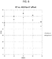
- FIG. 7 is a series of plots of retroreflective efficiency versus horizontal and vertical entrance angles for various third groove half angles.
- FIG. 8 is a plot of retroreflective efficiency versus horizontal entrance angle for various third groove half angles.
- FIG. 9A is a plot of a viewing zone superimposed with the position of a light beam returned by a retroreflective article having a 6-degree offset, a 29.5-degree third groove half angle, and a diffusing film. The incident light enters the article head-on.
- FIG. 9B is a plot of a viewing zone superimposed with the position of a light beam returned by the article of FIG. 9A .
- the incident light enters the article with a direction tilted 20 degrees to the right of, and 15 degrees below, the head-on direction.
- FIG. 10A is a plot of a viewing zone superimposed with the position of a light beam returned by a retroreflective article having a 6-degree offset, a 44.5-degree third groove half angle, and a diffusing film. The incident light enters the article head-on.
- FIG. 10B is a plot of a viewing zone superimposed with the position of a light beam returned by the article of FIG. 10A .
- the incident light enters the article with a direction tilted 20 degrees to the right of, and 15 degrees below, the head-on direction.
- FIG. 11A is a plot of a viewing zone offset 0.3 m behind the projector superimposed with the position of a light beam returned by a retroreflective article having a 6-degree offset, a 29.5-degree third groove half angle, and a diffusing film. The incident light enters the article head-on.
- FIG. 11B is a plot of a viewing zone offset 0.3 m behind the projector superimposed with the position of a light beam returned by the article of FIG. 11A .
- the incident light enters the article with a direction tilted 20 degrees to the right of, and 15 degrees below the head-on direction.
- FIG. 12 presents top-down illustrations of viewing retroreflective articles having an HG3 value in the range from 40 degrees to 45 degrees from a position offset behind a projector.
- FIG. 13 is a plot of the positions of two vertically asymmetrical light beams returned by a retroreflective article having dihedral angle errors that are not balanced.
- the present disclosure generally relates to retroreflective screens that provide advantageous combinations of performance characteristics, for example, when the screens are employed in projector-based displays.
- the inventors have determined that it is beneficial for a screen to reflect light back preferentially, or almost exclusively, to specific viewing regions located at different positions relative to a projector, e.g., above and below the projector, that is the source of the incident light being reflected.
- Existing projection screens typically either scatter light in all directions or send light back somewhat preferentially in the general direction of the projector.
- the inventors have now discovered particular configurations of retroreflective elements that achieve both of these results. For example, the introduction of specific aberrations into the dihedral angles of cube corner retroreflective elements can beneficially cause light to deviate from perfect retroreflection. It has been discovered that by carefully controlling the configurations of the retroreflective elements arrayed on the screen, these deviations produce the desired reflection divergence patterns with two distinct viewing zones. These divergence patterns advantageously allow for applications in which the content viewed on the screen can depend strongly on the position of the viewer relative to the screen and the projector. For example, two viewers located above and below a projector could view the same content on the screen, while two other viewers at different locations above and below a different projector could view entirely different content on the same screen.
- inventive retroreflective screens also allow for very bright images in the viewing regions, since light is not wasted by scattering in all directions.
- Other benefits of the retroreflective articles or screens include a transparent appearance to the film, and relative uniformity of brightness across the screen and within the multiple viewing regions. For example, certain configurations of the provided retroreflective screens can compensate for horizontal brightness instabilities typically associated with viewing positions offset towards or away from the screen.
- a retroreflective article comprising a retroreflective film and a plurality of specific retroreflective elements disposed, e.g., embossed, on the back surface of the retroreflective film
- the retroreflective elements can be configured to reflect an incident light beam such that the majority of reflected light is divided into a first reflected light beam and a second reflected light beam.
- the retroreflective article (or the components thereof) can be configured such that at least 30%, e.g., at least 40%, at least 50%, at least 60%, at least 70%, at least 75%, at least 80%, at least 85%, at least 90%, at least 92%, at least 94%, at least 96%, at least 97%, at least 98%, or at least 99% of the reflected light is divided into the first and second reflected light beams.
- the incident light beam can originate from a light source that emits light at least in the direction of the retroreflective article. In a preferred embodiment, the incident light beam originates from a projector having an optical axis that is directed towards the retroreflective article or screen.
- the first and second reflected light beams reflected by the retroreflective article are directed to (at least) two different locations, e.g., on different (opposite) sides of the incident light beam.
- the incident light beam originates from a projector
- the retroreflective article is oriented substantially vertically
- the first and second reflected light beams are directed to viewing regions or zones that are above and below the location of the projector.
- the first reflected light beam may be offset from the incident light beam by a first reflected light angle that is greater than 1 degree, e.g., greater than 2 degrees, greater than 3 degrees, greater than 4 degrees, greater than 5 degrees, greater than 6 degrees, greater than 7 degrees, greater than 8 degrees, greater than 9 degrees, greater than 10 degrees, greater than 12 degrees, greater than 14 degrees, greater than 16 degrees, greater than 18 degrees, greater than 20 degrees, greater than 25 degrees, greater than 30 degrees, greater than 35 degrees, greater than 40 degrees, or greater than 45 degrees.
- the first reflected light angle can range from 1 degree to 45 degrees, e.g., from 1 degree to 25 degrees, from 5 degrees to 30 degrees, from 10 degrees to 35 degrees, from 15 degrees to 40 degrees, or from 25 degrees to 40 degrees.
- the first reflected light angle can range from 1 degree to 10 degrees, e.g., from 1 degree to 6 degrees, from 2 degrees to 7 degrees, from 3 degrees to 8 degrees, from 4 degrees to 9 degrees, or from 5 degrees to 10 degrees.
- the second reflected light beam can be offset from the incident light beam by a second reflected angle having a magnitude substantially identical to that of the first reflected angle, and a direction different from, e.g., opposite of, that of the first reflected light beam relative to the incident light beam.
- the limits and ranges discussed above for the first reflected angle are applicable to the second reflected angle.
- the first reflected light angle is greater than 4 degrees above the incident light beam (at an offset angle of 4 degrees)
- the second reflected light angle is greater than 4 degrees below the incident light beam (at an offset angle of ⁇ 4 degrees).
- the first and second reflected light angles can be, for example, greater than 5 degrees, greater than 6 degrees, greater than 7 degrees, greater than 8 degrees, greater than 9 degrees, greater than 10 degrees, greater than 12 degrees, greater than 14 degrees, greater than 16 degrees, greater than 18 degrees, greater than 20 degrees, greater than 25 degrees, greater than 30 degrees, greater than 35 degrees, greater than 40 degrees, or greater than 45 degrees above and below the incident light beam, respectively.
- the terms ⁇ x and ⁇ y refer to orthogonal components of the observation angle ⁇ x wherein ⁇ y lies in a vertical plane.
- angle having a magnitude substantially identical refers to a relationship between two angles wherein the absolute values of the angles are within 5 degrees of one another.
- two angles have a magnitude substantially identical to one another if the absolute values of the angles are within 4 degrees, within 3 degrees, within 2 degrees, within 1 degree, within 0.9 degrees, within 0.8 degrees, within 0.7 degrees, within 0.6 degrees, within 0.5 degrees, within 0.4 degrees, within 0.3 degrees, within 0.2 degrees, or within 0.1 degrees of one another.
- the first reflected light beam has a brightness that is substantially identical to that of the second reflected light beam.
- This feature allows viewers positioned in the viewing zones or regions associated with each of the two viewing zones or regions to observe on the screen an image with substantially the same light intensity.
- the term “brightness that is substantially identical” refers to a relationship between two brightness values wherein the first brightness value is within 20% of the second brightness value. For example, two brightness values are substantially identical if the first brightness value is within 18%, within 16%, within 14%, within 12%, within 10%, within 9%, within 8%, within 7%, within 6%, within 5%, within 4%, within 3%, within 2%, or within 1% of the second brightness value.
- the first reflected light beam has a brightness that is not substantially identical to that of the second reflected light beam.
- the retroreflective film has a front surface and a back surface that is opposite the front surface.
- the front surface can be substantially smooth.
- substantially smooth refers to an outer surface that is completely or mostly free of texturing such as voids, protrusions, grooves, or ridges. A surface can have minor indentations or raised portions, or other imperfections not intended during manufacture, and still be considered to be substantially smooth.
- the front surface is substantially planar. It is appreciated, however, that the front surface can alternatively have a curved or otherwise nonplanar geometry for at least a portion of its shape.
- the material of the retroreflective film can vary widely.
- the material of the retroreflective film can be a transparent plastic material, such as a polymer.
- the material can be selected from a wide variety of polymers, including, but not limited to, polycarbonates, polyesters, polystyrenes, polyarylates, styrene-acrylonitrile copolymers, urethane, acrylic acid esters, cellulose esters, ethylenically unsaturated nitrites, hard epoxy acrylates, acrylics and the like, with acrylic and polycarbonate polymers being preferred.
- the retroreflective film comprises acrylic.
- the retroreflective film comprises polycarbonate.
- the retroreflective film comprises both acrylic and polycarbonate.
- the retroreflective film includes a prism layer and a cap layer, wherein the prism layer comprises one of acrylic or polycarbonate, and wherein the cap layer comprises the other of acrylic or polycarbonate.
- the retroreflective article further comprises a plurality of retroreflective elements disposed, e.g., embossed, on the back surface of the retroreflective film.
- the plurality of retroreflective elements can alternatively be disposed on the front surface of the retroreflective film, and the discussion relating to the retroreflective elements disposed on the back surface is applicable to retroreflective elements disposed on the front surface.
- the composition of the retroreflective elements can vary widely.
- the retroreflective elements can comprise metal, e.g., can be metallized.
- the retroreflective elements are air-backed. The use of air-backed retroreflective elements can give a semi-transparent or translucent character to the retroreflective film and the retroreflective article or screen.
- the retroreflective elements each have the shape of a non-equilateral triangular pyramid prism, e.g., an isosceles triangular pyramid prism, and each prism comprises multiple faces and a base.
- the triangular shape of each prism face and base can be non-equilateral, e.g., isosceles.
- Each of the prisms can be canted, and can have a triangular base that can be in the shape of an isosceles triangle.
- two of the three faces have substantially the same shape and size.
- Each triangular face and base comprises three sides.
- two of the three triangular base sides differ in length such that the ratio of the length of the smaller side to the length of the larger side ranges from 80% to 92.5%, e.g., from 80% to 87.5%, from 81.25% to 88.75%, from 82.5% to 90%, from 83.75% to 91.25%, or from 85% to 92.5%.
- the ratio of the smaller side length to the larger side length ranges from 83% to 90%, e.g., from 83% to 87.2%, from 83.7% to 87.9%, from 84.4% to 88.6%, from 85.1% to 89.3%, or from 85.8% to 90%.
- the ratio of the length of the smaller side to the length of the larger side can be at least 80%, at least 81.25%, at least 82.5%, at least 83.75%, at least 85%, at least 86.25%, at least 87.5%, at least 88.75%, at least 90%, or at least 91.25%.
- the ratio of the length of the smaller side to the length of the larger side can be less than 92.5%, less than 91.25%, less than 90%, less than 88.75%, less than 87.5%, less than 86.25%, less than 85%, less than 83.75%, less than 82.5%, or less than 81.25%.
- FIG. 1 illustrates a top view of one of the plurality of non-equilateral triangular pyramid prisms.
- the prisms are each in the shape of a cube corner, and can also be referred to as cube corner prisms.
- the prism 100 has a first 101 , second 102 , and third 103 triangular face that intersect at an apex 104 configured to point away from the back surface of the retroreflective film.
- Three dihedral angles 105 , 106 , and 107 are formed between faces 101 and 102 , between faces 101 and 103 , and between faces 102 and 103 , respectively. If the triangular pyramid prism has the shape of an orthogonal cube corner, then each of the dihedral angles is 90 degrees.
- dihedral angle error refers to the difference between the actual dihedral angle and 90 degrees.
- Each non-equilateral triangular pyramid prism has three dihedral angle errors—a first dihedral angle error (e 1 ), a second dihedral angle error (e 2 ), and a third dihedral angle error (e 3 ).
- the third dihedral angle error (e 3 ) is defined as the dihedral angle error between the two faces with similar, but mirrored (i.e., substantially congruent) shape.
- substantially congruent refers to a relationship between different shapes wherein the lengths of analogous sides of the different shapes differ from one another by less than 20% (e.g., less than 18%, less than 16%, less than 14%, less than 12%, less than 10%, less than 8%, less than 6%, less than 4%, or less than 2%), and the analogous interior angles of the different shapes differ from one another by less than 20% (e.g., less than 18%, less than 16%, less than 14%, less than 12%, less than 10%, less than 8%, less than 6%, less than 4%, or less than 2%).
- the offset of the first and second reflected light beams relative to the incident light beam is a function of the prism dihedral angles, and that these reflected light beams can be controlled by aberrating the prism dihedral angles. If the base of the isosceles triangle is oriented vertically, then by configuring the dihedral angle between the two substantially congruent faces to differ significantly from the nominal value of 90 degrees (i.e., setting e 3 to differ significantly from zero), the returning beam can be divided into two narrow reflected beams, with one deviating upwards and the other downwards.
- FIG. 2 shows a graph of the positions of two such deviated beams retroreflected by an array of cube corner isosceles triangle prisms.
- the reflected light beams are not as narrow as shown in FIG. 2 , but are instead broadened as shown in FIG. 3 .
- Such reflected beams can be achieved via control of the dihedral angles of the prisms, as discussed in more detail below.
- each prism has three dihedral angles, with the third dihedral angle defined as the dihedral angle between the prism faces having mirrored similar shapes.
- the average of the third dihedral angle errors of all prisms of the retroreflective element array is less than 0 degrees.
- the average of the third dihedral angle errors can range, for example and without limitation, from 0 degrees to ⁇ 10 degrees, e.g., from 0 degrees to ⁇ 6 degrees, from ⁇ 1 degrees to ⁇ 7 degrees, from ⁇ 2 degrees to ⁇ 8 degrees, from ⁇ 3 degrees to ⁇ 9 degrees, or from ⁇ 4 degrees to ⁇ 10 degrees.
- the average of the third dihedral angle errors can range from 0 degrees to ⁇ 4 degrees, e.g., from 0 degrees to ⁇ 2.4 degrees, from ⁇ 0.4 degrees to ⁇ 2.8 degrees, from ⁇ 0.8 degrees to ⁇ 3.2 degrees, from ⁇ 1.2 degrees to ⁇ 3.6 degrees, or from ⁇ 1.6 degrees to ⁇ 4 degrees.
- the average of the third dihedral angle errors can be greater than ⁇ 10 degrees, greater than ⁇ 9 degrees, greater than ⁇ 8 degrees, greater than ⁇ 7 degrees, greater than ⁇ 6 degrees, greater than ⁇ 5 degrees, greater than ⁇ 4 degrees, greater than ⁇ 3 degrees, greater than ⁇ 2 degrees, or greater than ⁇ 1 degrees.
- the average of the third dihedral angle errors can be less than ⁇ 1 degree, less than ⁇ 2 degrees, less than ⁇ 3 degrees, less than ⁇ 4 degrees, less than ⁇ 5 degrees, less than ⁇ 6 degrees, less than ⁇ 7 degrees, less than ⁇ 8 degrees, or less than ⁇ 9 degrees.
- Large negative values of e 3 can be used to achieve the pattern of offset retroreflected light beams.
- a similar offset can be achieved with large positive values of e 3 , but the use of negative values, as opposed to positive values, can give an efficiency boost to the cube corner prisms, as discussed in more detail below.
- the average of the first and/or second dihedral angle errors of all prisms of the retroreflective element array has a magnitude that is less than 0.5 degrees, e.g., less than 0.4 degrees, less than 0.3 degrees, less than 0.2 degrees, or less than 0.1 degrees. In some embodiments, the average of the first and/or second dihedral angle errors of all prisms of the retroreflective element array has a magnitude that is greater than 0.01 degrees, e.g., greater than 0.1 degrees, greater than 0.2 degrees, greater than 0.3 degrees, or greater than 0.4 degrees.
- the average of the first and/or second dihedral angle errors can, for example, range from 0 degrees to 0.3 degrees, from 0.05 degrees to 0.35 degrees, from 0.1 degrees to 0.4 degrees, from 0.15 degrees to 0.45 degrees, or from 0.2 degrees to 0.5 degrees.
- the magnitude of each dihedral angle error of each prism of the retroreflective element array ranges from 0.01 degrees to 10 degrees.
- the magnitude of each dihedral angle error can range, for example and without limitation, from 0.01 degrees to 6 degrees, from 1 degrees to 7 degrees, from 2 degrees to 8 degrees, from 3 degrees to 9 degrees, or from 4 degrees to 10 degrees.
- the magnitude of each dihedral angle error can range from 0.01 degrees to 4 degrees, e.g., from 0.01 degrees to 2.4 degrees, from 0.4 degrees to 2.8 degrees, from 0.8 degrees to 3.2 degrees, from 1.2 degrees to 3.6 degrees, or from 1.6 degrees to 4 degrees.
- the magnitude of each dihedral angle error can be less than 10 degrees, e.g., less than 9 degrees, less than 8 degrees, less than 7 degrees, less than 6 degrees, less than 5 degrees, less than 4 degrees, less than 3 degrees, less than 2 degrees, or less than 1 degrees.
- the magnitude of each dihedral angle error can be greater than 0.01 degrees, e.g., greater than 1 degree, greater than 2 degrees, greater than 3 degrees, greater than 4 degrees, greater than 5 degrees, greater than 6 degrees, greater than 7 degrees, greater than 8 degrees, or greater than 9 degrees.
- a diffusing film can be located, for example, directly adjacent to the front surface of the retroreflective film.
- an adhesive layer is employed to adhere the diffusing film to the front surface.
- the adhesive layer can be directly adjacent to the front surface of the retroreflective film, and the diffusing film can be directly adjacent to the adhesive layer, e.g., the adhesive layer can be sandwiched between the diffusing film and the retroreflective film.
- one or more other films or layers are positioned between the diffusing film and the front surface of the retroreflective film.
- the diffusing film is itself a component layer of the retroreflective film, and is located between the front and back surfaces of the retroreflective layer.
- the diffusing film can comprise light-diffusing particles dispersed in a matrix material, wherein the light-diffusing particles have a refractive index that is different from the refractive index of the matrix.
- the light-diffusing particles can vary in color, e.g., can be white or black, or substantially white or substantially black, with other colors being contemplated as well.
- the light-diffusing particles can be transparent, or substantially so.
- the light-diffusing particles can comprise particles selected from the group consisting of white particles or particles that are substantially white, black particles or particles that are substantially black, transparent particles or particles that are substantially transparent, and combinations thereof.
- the light-diffusing particles can comprise titanium oxide (TiO 2 ), silicon dioxide (SiO 2 ), calcium carbonate (CaCO 3 ), barium sulfate (BaSO 4 ), or combinations thereof.
- the light-diffusing particles can include a material comprising an organic or inorganic compound such as, for example, silicone resin, polytetrafluoroethylene (PTFE), roughened quartz, flashed opal, or combinations thereof.
- the light-diffusing particles can include hollow structures or hollow particles such as hollow glass beads or hollow resin beads, or hollow structures made from other materials.
- the diffusing film is a structured diffuser, e.g., a diffuser comprising a patterned surface.
- the patterned surface of the diffuser is a holographically generated relief pattern.
- the structured or patterned surface can be on the inner face of the diffuser, e.g., the diffuser surface facing the retroreflective film, or on the outer face of the diffuser, e.g., the diffuser surface facing opposite the retroreflective film.
- the surface relief pattern of the diffuser can be anisotropic, such that the pattern is elliptical. Such an anisotropic surface relief pattern can be used to broaden the reflected light beams by differing degrees in different directions.
- the diffusing film comprises an anisotropic surface relief pattern configured to reflect light with a greater angle of diffusion in the horizontal x direction than in the vertical y direction. In some embodiments, the diffusing film comprises an anisotropic surface relief pattern configured to reflect light with a greater angle of diffusion in the vertical y direction than in the horizontal y direction.
- the diffusing film can have a full-width half-maximum angle of diffusion in a vertical y direction that is less than 2 degrees, e.g., less than 1.8 degrees, less than 1.6 degrees, less than 1.4 degrees, less than 1.2 degrees, less than 1 degree, less than 0.9 degrees, less than 0.8 degrees, less than 0.7 degrees, less than 0.6 degrees, or less than 0.5 degrees.
- the full-width half-maximum angle of diffusion in the y direction can, for example, range from 0 degrees to 2 degrees, e.g., from 0 degrees to 1.2 degrees, from 0.2 degrees to 1.4 degrees, from 0.4 degrees to 1.6 degrees, from 0.6 degrees to 1.8 degrees, or from 0.8 degrees to 2 degrees.
- the diffusing film can have a full-width half-maximum angle of diffusion in a horizontal x direction that is greater than 1.5 degrees, e.g., greater than 1.8 degrees, greater than 2.1 degrees, greater than 2.4 degrees, greater than 2.7 degrees, greater than 3 degrees, greater than 3.5 degrees, greater than 4 degrees, greater than 4.5 degrees, or greater than 5 degrees.
- the full-width half-maximum angle of diffusion in the x direction can, for example, range from 0 degrees to 5 degrees, e.g., from 0 degrees to 3 degrees, from 0.5 degrees to 3.5 degrees, from 1 degrees to 4 degrees, from 1.5 degrees to 4.5 degrees, or from 2 degrees to 5 degrees.
- the use of such a larger horizontal diffusion angle can allow for multiple horizontal viewing positions. This can be useful, for example, when accommodating multiple side-by-side viewers.
- the diffusing film has a full-width half-maximum angle of diffusion in a vertical y direction that is less than 1 degree, and a full-width half-maximum angle of diffusion in a horizontal x direction that is greater than 3 degrees.
- the diffusing film can have a full-width half-maximum angle of diffusion in a horizontal x direction that is less than 2 degrees, e.g., less than 1.8 degrees, less than 1.6 degrees, less than 1.4 degrees, less than 1.2 degrees, less than 1 degree, less than 0.9 degrees, less than 0.8 degrees, less than 0.7 degrees, less than 0.6 degrees, or less than 0.5 degrees.
- the full-width half-maximum angle of diffusion in the x direction can, for example, range from 0 degrees to 2 degrees, e.g., from 0 degrees to 1.2 degrees, from 0.2 degrees to 1.4 degrees, from 0.4 degrees to 1.6 degrees, from 0.6 degrees to 1.8 degrees, or from 0.8 degrees to 2 degrees.
- the diffusing film can have a full-width half-maximum angle of diffusion in a vertical y direction that is greater than 1.5 degrees, e.g., greater than 1.8 degrees, greater than 2.1 degrees, greater than 2.4 degrees, greater than 2.7 degrees, greater than 3 degrees, greater than 3.5 degrees, greater than 4 degrees, greater than 4.5 degrees, or greater than 5 degrees.
- the full-width half-maximum angle of diffusion in the y direction can, for example, range from 0 degrees to 5 degrees, e.g., from 0 degrees to 3 degrees, from 0.5 degrees to 3.5 degrees, from 1 degrees to 4 degrees, from 1.5 degrees to 4.5 degrees, or from 2 degrees to 5 degrees.
- the use of such a larger vertical diffusion angle can allow for multiple vertical viewing positions. This can be useful, for example, when accommodating viewers with differing heights.
- the diffusing film has a full-width half-maximum angle of diffusion in a horizontal x direction that is less than 1 degree, and a full-width half-maximum angle of diffusion in a vertical y direction that is greater than 3 degrees.
- This configuration beneficially spreads the light in the vertical direction which can be useful for situations in which it is desirable to limit the horizontal spread of the light, e.g. light sent back for viewing by just one person, but allows for multiple vertical viewing positions, e.g. accommodating viewers with differing heights.
- the superimposed rectangular region shown in FIG. 4 represents a desired viewing region which is serviced by the combination of retroreflective film and diffusing film.
- a diffusing film as a beam broadening technique can be combined with the aforementioned modification of dihedral angle errors to produce an optimal profile for a given application.
- each technique can be employed separately.
- the dihedral angle technique can be advantageous, for example, if it is desired for the transitions from bright to dark to be fairly abrupt. This technique can, though, require tooling for each new design in a process that can be costly and time-consuming.
- the diffusing film technique can be advantageous, for example, if it is desired to hide seams in the prismatic film.
- Different diffusing films can also be matched with different prismatic films to accommodate the needs of various applications with increased flexibility.
- This technique can, though, add cost to the display screen, and produce light intensity or brightness transitions that are less abrupt.
- the adjustment of the dihedral angles of the cube corner prism retroreflective elements can also influence the shapes of the reflected light beams returned by the retroreflective article.
- the size of the viewing regions or patches can be increased as desired, while maintaining sufficient uniformity of illumination within each patch and among the two patches.
- the retroreflective film is used in conjunction with a diffusing film, which can help to reduce the visibility of seam lines and to improve in screen uniformity. This use of the diffusing film and the control of the dihedral angles also can increase the size of the patch and help with uniformity within the patch.
- the design of the prisms can be configured to provide for a smaller patch if used with a stronger diffuser, or a larger patch if used with a weaker diffuser or no diffuser.
- a weaker diffuser or no diffuser can be selected.
- a stronger diffuser can be selected.
- the width and height of the patches can be controlled independently, either by using anisotropic diffusers, or by varying the dihedral angle pattern to affect the aspect ratio of the patch. Combinations of these approaches can provide more flexibility.
- the configurations of the retroreflective elements disposed on the back surface of the retroreflective film can be determined by geometries of sets of substantially parallel grooves in the back surface, wherein the sets determine the positioning of the retroreflective elements.
- the configurations and arrangements of these groove sets can therefore determine the cube cant, prism depth, and/or dihedral angle errors of prism retroreflective elements.
- substantially parallel grooves refers to grooves that are substantially parallel to one another, e.g. parallel to one another.
- Each of the grooves has a groove axis extending along the length of the groove, wherein the angle between the groove axes of two substantially parallel grooves has a magnitude less than 5 degrees, e.g., less than 4 degrees, less than 3 degrees, less than 2 degrees, or less than 1 degree.
- the respective grooves may differ from one another in slope by a magnitude less than 5 degrees, e.g., less than 4 degrees, less than 3 degrees, less than 2 degrees, or less than 1 degree, when compared to the slope of a basis line.
- FIGS. 5A-5D Illustrative examples of the groove sets are shown in FIGS. 5A-5D , which provide an overview of a cutting process used to produce the retroreflective elements.
- a first set of substantially parallel grooves is shown cut into a substrate of which a replica or a cast can be used to emboss the retroreflective film back surface.
- the grooves can be cut using a cutting tool having a pointed tip.
- the cutting tool tip also includes a flat region, such that a flat region is created in the substrate between adjacent retroreflective elements. The presence of such flat regions can boost transparency, but at the cost of efficiency.
- Each groove is cut along a groove axis, and typically has a v shape with two intersecting groove sides.
- each groove of the first set has half angles “a” and “b” that are defined by corresponding “a” and “b” angles on the surface of the shown cutting tool.
- the half angles are formed between the groove sides and a plane parallel to the groove axis and perpendicular to the plane of the substrate or the back surface of the retroreflective film.
- the sizes and tilts of the cutting tool, grooves, and retroreflective elements have been exaggerated in this and the following figures for clarity.
- each groove of the first set is separated from the adjacent groove of the set by a substantially identical spacing, e.g., a first spacing.
- the first spacing can, for example, range from 0.03 mm to 0.27 mm, e.g., from 0.03 mm to 0.15 mm, from 0.06 mm to 0.18 mm, from 0.09 mm to 0.21 mm, from 0.12 mm to 0.24 mm, or from 0.15 mm to 0.27 mm.
- the first spacing can range from 0.1 mm to 0.2 mm, e.g., from 0.1 to 0.16 mm, from 0.11 mm to 0.17 mm, from 0.12 mm to 0.18 mm, from 0.13 mm to 0.19 mm, or from 0.14 mm to 0.2 mm.
- the first spacing can be greater than 0.03 mm, e.g., greater than 0.06 mm, greater than 0.09 mm, greater than 0.12 mm, greater than 0.15 mm, greater than 0.18 mm, greater than 0.21 mm, or greater than 0.24 mm. In terms of lower limits, the first spacing can be less than 0.27 mm, e.g., less than 0.24 mm, less than 0.21 mm, less than 0.18 mm, less than 0.15 mm, less than 0.12 mm, less than 0.09 mm, or less than 0.06 mm.
- each groove of the second set is separated from the adjacent groove of the set by a substantially identical spacing (i.e., a second spacing).
- the second spacing can be, for example, range from 0.03 mm to 0.27 mm, e.g., from 0.03 mm to 0.15 mm, from 0.06 mm to 0.18 mm, from 0.09 mm to 0.21 mm, from 0.12 mm to 0.24 mm, or from 0.15 mm to 0.27 mm.
- the second spacing can range from 0.1 mm to 0.2 mm, e.g., from 0.1 to 0.16 mm, from 0.11 mm to 0.17 mm, from 0.12 mm to 0.18 mm, from 0.13 mm to 0.19 mm, or from 0.14 mm to 0.2 mm.
- the second spacing can be greater than 0.03 mm, greater than 0.06 mm, greater than 0.09 mm, greater than 0.12 mm, greater than 0.15 mm, greater than 0.18 mm, greater than 0.21 mm, or greater than 0.24 mm. In terms of lower limits, the second spacing can be less than 0.27 mm, less than 0.24 mm, less than 0.21 mm, less than 0.18 mm, less than 0.15 mm, less than 0.12 mm, less than 0.09 mm, or less than 0.06 mm.
- the grooves of the first set have a spacing substantially identical to that of the grooves of the second set.
- spacing substantially identical refers to a relationship between two spacings wherein the spacings are within 20% of one another.
- two spacings have a spacing substantially identical to one another if the spacings are within 18%, within 16%, within 14%, within 12%, within 10%, within 9%, within 8%, within 7%, within 6%, within 5%, within 4%, within 3%, within 2%, or within 1% of one another.
- a third set of substantially parallel grooves is shown cut into the substrate along with the first and second groove sets.
- the grooves of this third set have half angles “c” and “d” that are defined by corresponding “c” and “d” angles on the surface of the shown cutting tool.
- each groove of the third set is separated from the adjacent groove of the set by a substantially identical spacing (i.e., a third spacing).
- the third spacing can be, for example, range from 0.03 mm to 0.27 mm, e.g., from 0.03 mm to 0.15 mm, from 0.06 mm to 0.18 mm, from 0.09 mm to 0.21 mm, from 0.12 mm to 0.24 mm, or from 0.15 mm to 0.27 mm.
- the third spacing can range from 0.1 mm to 0.2 mm, e.g., from 0.1 to 0.16 mm, from 0.11 mm to 0.17 mm, from 0.12 mm to 0.18 mm, from 0.13 mm to 0.19 mm, or from 0.14 mm to 0.2 mm. In terms of upper limits, the third spacing can be greater than 0.03 mm, greater than 0.06 mm, greater than 0.09 mm, greater than 0.12 mm, greater than 0.15 mm, greater than 0.18 mm, greater than 0.21 mm, or greater than 0.24 mm.
- the third spacing can be less than 0.27 mm, less than 0.24 mm, less than 0.21 mm, less than 0.18 mm, less than 0.15 mm, less than 0.12 mm, less than 0.09 mm, or less than 0.06 mm.
- the grooves of the third set have a spacing smaller than the first and second spacing. In some embodiments, the grooves of the third set have a spacing larger than the first and second spacing.
- FIG. 5D is a plan view of an array of cube corner prisms bounded by the first, second, and third grooves in the back surface of a retroreflective film in accordance with an embodiment.
- the illustration shows the array of cube corner prisms bounded by the three sets of substantially parallel grooves.
- the particular geometry of an individual cube corner element of the array will depend on the particular half grooves of the element border.
- a cube corner element can be bounded by an “a” half groove from a first set groove, an “a” half groove from a second set groove, and a “c” half groove from a third set groove.
- the cube corner can be considered an “aac” element.
- cube corners can alternatively be “aad”, “abc”, “abd”, “bac”, “bad”, “bbd”, or “bbc” elements.
- one or both of the half angles of the third grooves ranges from 25 degrees to 28.5 degrees, e.g., from 25 degrees to 26.9 degrees, from 25.4 degrees to 27.3 degrees, from 25.8 degrees to 27.7 degrees, from 26.2 degrees to 28.1 degrees, or from 26.6 degrees to 28.5 degrees.
- One or both of the third groove half angles can range from 43.5 degrees to 45 degrees, e.g., from 43.5 degrees to 44.2 degrees, from 43.7 degrees to 44.4 degrees, from 43.9 degrees to 44.6 degrees, from 44.1 degrees to 44.8 degrees, or from 44.3 degrees to 45 degrees.
- one or both of the third groove half angles can be greater than 25 degrees, e.g., greater than 25.4 degrees, greater than 25.8 degrees, greater than 26.2 degrees, greater than 26.6 degrees, greater than 26.9 degrees, greater than 27.3 degrees, greater than 27.7 degrees, greater than 28.1 degrees, greater than 43.5 degrees, greater than 43.7 degrees, greater than 43.9 degrees, greater than 44.1 degrees, greater than 44.3 degrees, greater than 44.4 degrees, greater than 44.6 degrees, or greater than 44.8 degrees.
- one or both of the third groove half angles can be less than 45 degrees, e.g., less than 44.8 degrees, less than 44.6 degrees, less than 44.4 degrees, less than 44.2 degrees, less than 44.1 degrees, less than 43.9 degrees, less than 43.7 degrees, less than 28.5 degrees, less than 28.1 degrees, less than 27.7 degrees, less than 27.3 degrees, less than 26.9 degrees, less than 26.6 degrees, less than 26.2 degrees, less than 25.8 degrees, or less than 25.4 degrees.
- the depth of the grooves gives each of the cube corner prisms of the array a cube corner depth.
- the cube corner depth is defined as the distance between the maximum height of the cube corner prism and the base of the cube corner prism.
- the cube corner depth can, for example, range from 1 mil to 5 mils, e.g., from 1 mil to 3.4 mils, from 1.4 mils to 3.8 mils, from 1.8 mils to 4.2 mils, from 2.2 mils to 4.6 mils, or from 2.6 mils to 5 mils.
- the cube corner depth can range from 2.2 mils to 3.8 mils, e.g., from 2.2 mils to 3 mils, from 2.4 mils to 3.2 mils, from 2.6 mils to 3.4 mils, from 2.8 mils to 3.6 mils, or from 3 mils to 3.8 mils.
- the cube corner depth can be greater than 1 mil, e.g., greater than 1.4 mils, greater than 1.8 mils, greater than 2.2 mils, greater than 2.6 mils, greater than 3 mils, greater than 3.4 mils, greater than 3.8 mils, greater than 4.2 mils, or greater than 4.6 mils.
- the cube corner depth can be less than 5 mils, e.g., less than 4.6 mils, less than 4.2 mils, less than 3.8 mils, less than 3.4 mils, less than 3 mils, less than 2.6 mils, less than 2.2 mils, less than 1.8 mils, or less than 1.4 mils.
- cant as the cant of the unaberrated cube having the same cube shape, and we also consider the third groove half angle (HG 3 ).
- This angle has functional relevance for transparency effects, and also for the horizontal entrance angularity.
- prism designs that use a negative value of e 3 are always more efficient in returning light, with a value of HG 3 of approximately 35 degrees giving the highest efficiency.
- the cube corner prisms of the retroreflective article are canted face-more-parallel, e.g., at a cant ranging from ⁇ 3 degrees to ⁇ 10 degrees.
- the cube corner prisms can have a cant ranging from ⁇ 3 degrees to ⁇ 8 degrees, from ⁇ 3.5 degrees to ⁇ 8.5 degrees, from ⁇ 4 degrees to ⁇ 9 degrees, from ⁇ 4.5 degrees to ⁇ 9.5 degrees, or from ⁇ 5 degrees to ⁇ 10 degrees.
- the cant can range from ⁇ 5 degrees to ⁇ 8 degrees, e.g., from ⁇ 5 degrees to ⁇ 6.8 degrees, from ⁇ 5.3 degrees to ⁇ 7.1 degrees, from ⁇ 5.6 degrees to ⁇ 7.4 degrees, from ⁇ 5.9 degrees to ⁇ 7.7 degrees, or from ⁇ 6.2 degrees to ⁇ 8 degrees.
- the cant can be greater than ⁇ 10 degrees, e.g., greater than ⁇ 9.5 degrees, greater than ⁇ 9 degrees, greater than ⁇ 8.5 degrees, greater than ⁇ 8 degrees, greater than ⁇ 7.5 degrees, greater than ⁇ 7 degrees, greater than ⁇ 6.5 degrees, greater than ⁇ 6 degrees, greater than ⁇ 5.5 degrees, greater than ⁇ 5 degrees, greater than ⁇ 4.5 degrees, greater than ⁇ 4 degrees, or greater than ⁇ 3.5 degrees.
- the cant can be less than ⁇ 3 degrees, e.g., less than ⁇ 3.5 degrees, less than ⁇ 4 degrees, less than ⁇ 4.5 degrees, less than ⁇ 5 degrees, less than ⁇ 5.5 degrees, less than ⁇ 6 degrees, less than ⁇ 6.5 degrees, less than ⁇ 7 degrees, less than ⁇ 7.5 degrees, less than ⁇ 8 degrees, less than ⁇ 8.5 degrees, less than ⁇ 9 degrees, or less than ⁇ 9.5 degrees.
- the cube corner prisms of the retroreflective article are canted edge-more-parallel, e.g., at a cant ranging from 3 degrees to 10 degrees.
- the cube corner prisms can have a cant ranging from 3 degrees to 8 degrees, from 3.5 degrees to 8.5 degrees, from 4 degrees to 9 degrees, from 4.5 degrees to 9.5 degrees, or from 5 degrees to 10 degrees.
- the cant can range from 5 degrees to 8 degrees, e.g., from 5 degrees to 6.8 degrees, from 5.3 degrees to 7.1 degrees, from 5.6 degrees to 7.4 degrees, from 5.9 degrees to 7.7 degrees, or from 6.2 degrees to 8 degrees.
- the cant can be less than 10 degrees, less than 9.5 degrees, less than 9 degrees, less than 8.5 degrees, less than 8 degrees, less than 7.5 degrees, less than 7 degrees, less than 6.5 degrees, less than 6 degrees, less than 5.5 degrees, less than 5 degrees, less than 4.5 degrees, less than 4 degrees, or less than 3.5 degrees.
- the cant can be greater than 3 degrees, e.g., greater than 3.5 degrees, greater than 4 degrees, greater than 4.5 degrees, greater than 5 degrees, greater than 5.5 degrees, greater than 6 degrees, greater than 6.5 degrees, greater than 7 degrees, greater than 7.5 degrees, greater than 8 degrees, greater than 8.5 degrees, greater than 9 degrees, or greater than 9.5 degrees.
- canted face-more-parallel and “canted edge-more parallel” as used herein refer to the positioning of the cube relative to the principal refracted ray.
- the cube is “face-more-parallel” or “edge-more-parallel” depending upon whether the face angle with respect to the principal refracted ray that is most different from 35.26 degrees is respectively greater or less than 35.26 degrees.
- the range of values for ⁇ x and ⁇ y shown are typical for projection screens.
- the positions of angle combinations ( ⁇ x , ⁇ y ) shown on the graph roughly correspond topologically to (x, y) positions on a flat display screen with the projector located opposite the top center of the screen.
- the efficiency value R T at each position then is one factor in determining the brightness of the corresponding x,y position on the screen.
- the uniformity of retroreflective efficiency improves, although there still are some dark regions (R T ⁇ 10%).
- the efficiency uniformity improves further, such that for all regions on the screen R T >15%.
- third groove half angle within the range between 25 degrees and 28.5 degrees, or within the range between 43.5 degrees and 45.0 degrees. These third groove half angle values correspond to cube corner prisms having a sizable negative or positive cant.
- FIG. 8 presents a graph plotting the retroreflective efficiency as a function of the horizontal entrance angle ( ⁇ x ) for five different third groove half angle values (25 degrees, 30 degrees, 35 degrees, 40 degrees, and 45 degrees).
- This third groove half angle range between 43.5 degrees and 45 degrees is that it can provide superior horizontal pattern stability. Changes in ⁇ x and ⁇ y can move the pattern of retroreflected light horizontally. However, in the case of an HG 3 value in the range between 43.5 degrees and 45 degrees, changes due to ⁇ x tend to compensate for changes in ⁇ y , resulting in the pattern staying more stable in the horizontal direction.
- FIG. 9A shows a plot of the position of a light beam returned by a retroreflective article having an offset of 6 degrees, a third groove half angle of 29.5 degrees, and a diffusing film.
- the vertical shift to the light position is inconsequential since the desired viewing region also shifts vertically. However, the horizontal shift causes the light return to decrease substantially, particularly in the left portion of the desired viewing region.
- the prism cant is changed such that the third groove half angle is 44.4 degrees, then the light return for head on viewing is as shown on FIG. 10A .
- the pattern of light return again shifts both horizontally and vertically as shown in FIG. 10B .
- the vertical downward shift of the pattern of light can be undesirable, but has a reduced negative effect since the pattern of light has a substantial vertical spread.
- shifting the desired viewing region downward e.g., by raising the projector
- this vertical shift can be easily accommodated.
- the horizontal shift in this case is significantly less than that of FIG. 9B , and can also be accommodated.
- the viewer positioned not directly above or below the projector, but instead offset from the projector in a direction either towards or farther away from the retroreflective article.
- This forward or backward offset introduces a horizontal instability in the desired viewing area due to parallax.
- an appropriately designed retroreflective article can compensate for the horizontal instability by providing an appropriate amount of horizontal pattern shift.
- FIG. 12 An additional advantageous outcome of this small half-angle design (e.g., a configuration having an HG 3 value between 25 degrees and 30 degrees) is that the overall brightness uniformity of the screen image can be considerably improved, as is shown in FIG. 12 .
- the left image of FIG. 12 is a top-down illustration of viewing a retroreflective article having an HG 3 value in the range from 40 degrees to 45 degrees from a position offset behind a projector and farther away from the retroreflective article.
- the right eye of the viewer is in a position far to the right of the return path of light reflecting back from the right side of the retroreflective article, while the left eye of the viewer is in a position far to the left of the return path of light reflecting back from the left side of the retroreflective article.
- FIG. 12 is a top-down illustration of viewing a small half-angle retroreflective article having an HG 3 value in the range of 25 degrees to 30 degrees from the offset position. In this case, all regions of the retroreflective article reflect to the general proximity of the center of the eyes, improving both brightness uniformity and perceived left and right eye brightness balance for the viewer.
- the HG 3 value for the small half-angle retroreflective article can, for example, range from 25 degrees to 30 degrees, e.g., from 25 degrees to 28 degrees, from 25.5 degrees to 28.5 degrees, from 26 degrees to 29 degrees, from 26.5 degrees to 29.5 degrees, or from 27 degrees to 30 degrees. In terms of upper limits, the HG 3 value can be less than 30 degrees, e.g., less than 29.5 degrees, less than 29 degrees, less than 28.5 degrees, less than 28 degrees, less than 27.5 degrees, less than 27 degrees, less than 26.5 degrees, less than 26 degrees, or less than 25.5 degrees.
- the HG 3 value can be greater than 25 degrees, e.g., greater than 25.5 degrees, greater than 26 degrees, greater than 26.5 degrees, greater than 27 degrees, greater than 28 degrees, greater than 29 degrees, or greater than 29.5 degrees.
- the efficiency of the retroreflective article can be reduced, resulting in lower overall brightness.
- certain characteristic perceived brightness instabilities can occur at sufficiently low values of ⁇ x (e.g., lower than 45 degrees), as can occur in certain screen projection scenarios. These undesirable instabilities can appear as sparkles, bright lines, or streaks on the retroreflective article or screen.
- the performance of the retroreflective article at larger entrance angles is diminished, and there can be a consequent lowering of the brightness at the edge of the retroreflective article.
- the retroreflective elements of the small half-angle retroreflective article are not produced using the technique of tilting the cutting tool to produce pattern spread. Instead, it can be more beneficial for certain applications to configure the retroreflective article to produce narrow reflected beams, and to obtain a desired pattern spread by the alternate means of a diffusing film. In this case, a stronger diffuser can be used, providing the additional benefits of effectively minimizing front surface specular reflection and hiding seams and other cosmetic defects.
- the diffusing film used with the small half-angle retroreflective article can have a full-width half-maximum angle of diffusion in a horizontal x-direction ranging, for example, from 1 degree to 4 degrees, e.g., from 1 degree to 2.8 degrees, from 1.3 degrees to 3.1 degrees, from 1.6 degrees to 3.4 degrees, from 1.9 degrees to 3.7 degrees, or from 2.2 degrees to 4 degrees.
- the horizontal x-direction diffusion angle of the diffuser can be less than 4 degrees, e.g., less than 3.7 degrees, less than 3.4 degrees, less than 3.1 degrees, less than 2.8 degrees, less than 2.5 degrees, less than 2.2 degrees, less than 1.9 degrees, less than 1.6 degrees, or less than 1.3 degrees.
- the horizontal x-direction diffusion angle of the diffuser can be greater than 1 degree, e.g., greater than 1.3 degrees, greater than 1.6 degrees, greater than 1.9 degrees, greater than 2.2 degrees, greater than 2.5 degrees, greater than 2.8 degrees, greater than 3.1 degrees, greater than 3.4 degrees, or greater than 3.7 degrees. Larger horizontal diffusion angles, e.g., greater than 4 degrees, and smaller horizontal diffusion angles, e.g., less than 1 degree, are also contemplated.
- the diffusing film used with the small half-angle retroreflective article can have a full-width half-maximum angle of diffusion in a vertical y-direction ranging, for example, from 3 degrees to 6 degrees, e.g., from 3 degrees to 4.8 degrees, from 3.3 degrees to 5.1 degrees, from 3.6 degrees to 5.4 degrees, from 3.9 degrees to 5.7 degrees, or from 4.2 degrees to 6 degrees.
- the vertical y-direction diffusion angle of the diffuser can be less than 6 degrees, e.g., less than 5.7 degrees, less than 5.4 degrees, less than 5.1 degrees, less than 4.8 degrees, less than 4.5 degrees, less than 4.2 degrees, less than 3.9 degrees, less than 3.6 degrees, or less than 3.3 degrees.
- the vertical y-direction diffusion angle of the diffuser can be greater than 3 degrees, e.g., greater than 3.3 degrees, greater than 3.6 degrees, greater than 3.9 degrees, greater than 4.2 degrees, greater than 4.5 degrees, greater than 4.8 degrees, greater than 5.1 degrees, greater than 5.4 degrees, or greater than 5.7 degrees. Larger vertical diffusion angles, e.g., greater than 6 degrees, and smaller vertical diffusion angles, e.g., less than 3 degrees, are also contemplated.
- the prisms of the small half-angle retroreflective article have a third dihedral angle error that has a magnitude greater than 1 degrees.
- the third dihedral angle error can, for example, range from ⁇ 4 degrees to ⁇ 1 degrees, e.g., from ⁇ 4 degrees to ⁇ 2.2 degrees, from ⁇ 3.7 degrees to ⁇ 1.9 degrees, from ⁇ 3.4 degrees to ⁇ 1.6 degrees, from ⁇ 3.1 degrees to ⁇ 1.3 degrees, or from ⁇ 2.8 degrees to ⁇ 1 degrees.
- the third dihedral angle error can be less than ⁇ 1 degrees, e.g., less than ⁇ 1.3 degrees, less than ⁇ 1.6 degrees, less than ⁇ 1.9 degrees, less than ⁇ 2.2 degrees, less than ⁇ 2.5 degrees.
- the third angle dihedral angle error can be greater than ⁇ 4 degrees. e.g., greater than ⁇ 3.7 degrees, greater than ⁇ 3.4 degrees, greater than ⁇ 3.1 degrees, greater than ⁇ 2.8 degrees, greater than ⁇ 2.5 degrees, greater than ⁇ 2.2 degrees, greater than ⁇ 1.9 degrees, greater than ⁇ 1.6 degrees, or greater than ⁇ 1.3 degrees. Larger third dihedral angle errors, e.g., greater than ⁇ 1 degrees, and smaller dihedral angle errors, e.g., less than ⁇ 4 degrees, are also contemplated.
- the third dihedral angle error can, for example, range from 1 degree to 4 degrees, e.g., from 1 degree to 2.8 degrees, from 1.3 degrees to 3.1 degrees, from 1.6 degrees to 3.4 degrees, from 1.9 degrees to 3.7 degrees, or from 2.2 degrees to 4 degrees. In terms of upper limits, the third dihedral angle error can be less than 4 degrees, e.g., less than 3.7 degrees, less than 3.4 degrees, less than 3.1 degrees, less than 2.8 degrees, less than 2.5 degrees, less than 2.2 degrees, less than 1.9 degrees, less than 1.6 degrees, or less than 1.3 degrees.
- the third dihedral angle error can be greater than 1 degree, e.g., greater than 1.3 degrees, greater than 1.6 degrees, greater than 1.9 degrees, greater than 2.2 degrees, greater than 2.5 degrees, greater than 2.8 degrees, greater than 3.1 degrees, greater than 3.4 degrees, or greater than 3.7 degrees. Larger dihedral angle errors, e.g., greater than 4 degrees, and smaller dihedral angle errors, e.g., less than 1 degree, are also contemplated.
- the first and second dihedral angle errors of the prisms of the retroreflective article are each 0 degrees.
- the prisms of the small half-angle retroreflective article are each canted edge-more-parallel at a cant greater than 0 degrees.
- the cant of each prism can, for example, range from 0 degrees to 10 degrees, e.g., from 0 degrees to 6 degrees, from 1 degree to 7 degree, from 2 degrees to 8 degrees, from 3 degrees to 9 degrees, or from 4 degrees to 10 degrees. In terms of upper limits, the cant of each prism can be less than 10 degrees, e.g., less than 9 degrees, less than 8 degrees, less than 7 degrees, less than 6 degrees, less than 5 degrees, less than 4 degrees, less than 3 degrees, less than 2 degrees, or less than 1 degree.
- the cant of each prism can be greater than 0 degrees, e.g., greater than 1 degree, greater than 2 degrees, greater than 3 degrees, greater than 4 degrees, greater than 5 degrees, greater than 6 degrees, greater than 7 degrees, greater than 8 degrees, or greater than 9 degrees. Larger prism cants, e.g., greater than 10 degrees, are also contemplated.
- the present disclosure also relates to a display system that includes the retroreflective article as described above.
- the system also includes a light source that produces the incident light beam at least in the direction of the retroreflective article.
- the light source is a projector configured to direct an incident light beam towards the retroreflective article.
- the incident light can be, for example, a still image or a video image.
- the system includes two or more light sources or projectors. Each of the one or more projectors can include one or more optical elements for directing and/or focusing an image or video onto the retroreflective article.
- Projectors can include, for example and without limitation, film projectors, cathode ray tube (CRT) projectors, laser projectors, Digital Light Processor (DLP) or Digital Micromirror Device (DMD) projectors, liquid crystal display (LCD) projectors, or liquid crystal on silicon (LCOS) projectors.
- CTR cathode ray tube
- DLP Digital Light Processor
- DMD Digital Micromirror Device
- LCD liquid crystal display
- LCOS liquid crystal on silicon
- the system can also include a computer processor operatively connected with a machine-readable non-transitory storage medium.
- Storage media can include any or all of the tangible memory of the computers, processors or the like, or associated modules thereof, such as various semiconductor memories, tape drives, disk drives and the like, which can provide non-transitory storage at any time for software programming. All or portions of the software can at times be communicated through the Internet or various other telecommunication networks. Such communications, for example, can enable loading of the software from one computer or processor into another, for example, from a management server or host computer into the computer platform of an application server.
- another type of media that can bear the software elements includes optical, electrical, and electromagnetic waves, such as used across physical interfaces between local devices, through wired and optical landline networks, and over various air-links.
- the physical elements that carry such waves, such as wired or wireless links, optical links or the like, also can be considered as media bearing the software.
- the storage medium can embody information indicative of instructions for causing the processor to perform operations.
- the operations can include, for example, controlling the light source or projector to direct the incident light beam towards the retroreflective article.
- a retroreflective article comprising: a retroreflective film comprising opposing front and back surfaces; and a plurality of retroreflective elements disposed on the back surface of the retroreflective film; wherein each of the retroreflective elements comprises a non-equilateral triangular pyramid prism bounded by one of a first set of substantially parallel and v-shaped first grooves, one of a second set of substantially parallel and v-shaped second grooves, and one of a third set of substantially parallel and v-shaped third grooves; wherein each of the grooves comprises a groove axis and two intersecting groove sides; wherein each groove side of a groove forms a half angle between the groove side and a plane parallel to the groove axis of the groove and orthogonal to the back surface of the retroreflective film; and wherein at least one of the half angles ranges from 25.0 degrees to 28.5 degrees, or ranges from 43.5 degrees to 45.0 degrees.
- each of the retroreflective elements comprises a first, second, and third triangular face; wherein the first, second, and third triangular faces intersect at an apex configured to point away from the back surface; wherein the first and second triangular faces are substantially congruent triangles; and wherein the third triangular face is not congruent with the first and second triangular faces.
- each prism has a first, second, and third dihedral angle error; and wherein the magnitude of each dihedral angle error ranges from 0.01 degrees to 10 degrees.
- each prism is canted at a cant angle ranging from ⁇ 5 degrees to ⁇ 8 degrees.
- each prism is canted at a cant angle ranging from 4 degrees to 8 degrees.
- retroreflective film comprises acrylic or polycarbonate.
- retroreflective article is a display screen.
- a retroreflective article comprising: a retroreflective film comprising opposing front and back surfaces; and a plurality of retroreflective elements disposed on the back surface of the retroreflective film; wherein each of the retroreflective elements is a non-equilateral triangular pyramid prism comprising a triangular base; and wherein the triangular base comprises two sides that differ in length from one another such that the ratio of the length of the smaller of the two sides to the length of the larger of the two sides ranges from 80% to 92.5%.
- each retroreflective element further comprises a first, second, and third triangular face; wherein the first, second, and third triangular faces intersect at an apex configured to point away from the back surface; wherein the first and second triangular faces are substantially congruent triangles; and wherein the third triangular face is not congruent with the first and second triangular faces.
- each prism has a first, second, and third dihedral angle error; and wherein the magnitude of each dihedral angle error ranges from 0.01 degrees to 10 degrees.
- each of the retroreflective elements comprises a non-equilateral triangular pyramid prism bounded by one of a first set of substantially parallel and v-shaped first grooves, one of a second set of substantially parallel and v-shaped second grooves, and one of a third set of substantially parallel and v-shaped third grooves; wherein adjacent first grooves are separated by a first spacing ranging from 0.1 mm to 0.2 mm; wherein adjacent second grooves are separated by a second spacing substantially identical to the first spacing; and wherein adjacent third grooves are separated by a third spacing smaller than the first and second spacing.
- each prism is canted at a cant angle ranging from ⁇ 5 degrees to ⁇ 8 degrees.
- each prism is canted at a cant angle ranging from 5 degrees to 8 degrees.
- retroreflective film comprises acrylic or polycarbonate.
- a retroreflective article comprising: a retroreflective film comprising opposing front and back surfaces; and a plurality of retroreflective elements disposed on the back surface of the retroreflective film; wherein each of the retroreflective elements comprises a non-equilateral triangular pyramid prism having a third dihedral angle error less than ⁇ 1 degrees; wherein each prism is bounded by one of a first set of substantially parallel and v-shaped first grooves, one of a second set of substantially parallel and v-shaped second grooves, and one of a third set of substantially parallel and v-shaped third grooves; wherein each of the grooves comprises a groove axis and two intersecting groove sides; wherein each groove side of a groove forms a half angle between the groove side and a plane parallel to the groove axis of the groove and orthogonal to the back surface of the retroreflective film; and wherein at least one of the half angles ranges from 25 degrees to 30 degrees.
- An embodiment of embodiment 42 or 43 further comprising: a diffusing film having: (1) a full-width half-maximum angle of diffusion of greater than 1 degree in a horizontal x-direction substantially parallel to the front surface of the retroreflective film when the front and back surfaces of the retroreflective film are positioned vertically, and (2) a full-width half-maximum angle of diffusion of greater than 3 degrees in a vertical y-direction substantially parallel to the front surface of the retroreflective film when the front and back surfaces of the retroreflective film are positioned vertically.
- each of the retroreflective elements comprises a first, second, and third triangular face; wherein the first, second, and third triangular faces intersect at an apex configured to point away from the back surface; wherein the first and second triangular faces are substantially congruent triangles; and wherein the third triangular face is not congruent with the first and second triangular faces.
- each prism is canted edge-more-parallel at a cant ranging from 4 degrees to 10 degrees.
- retroreflective film comprises acrylic or polycarbonate.
- a retroreflective article comprising: a retroreflective film comprising opposing front and back surfaces; and a plurality of retroreflective elements disposed on the back surface of the retroreflective film; wherein each of the retroreflective elements comprises a non-equilateral triangular pyramid prism bounded by one of a first set of substantially parallel and v-shaped first grooves, one of a second set of substantially parallel and v-shaped second grooves, and one of a third set of substantially parallel and v-shaped third grooves; wherein each of the grooves comprises a groove axis and two intersecting groove sides; wherein each groove side of a groove forms a half angle between the groove side and a plane parallel to the groove axis of the groove and orthogonal to the back surface of the retroreflective film; wherein at least one of the half angles ranges from 25.0 degrees to 30.0 degrees; and wherein each prism is canted edge-more-parallel at a cant angle greater than 0 degrees.
- each prism is canted at a cant angle ranging from 4 degrees to 10 degrees.
- An embodiment of embodiment 53 or 54 further comprising: a diffusing film having: (1) a full-width half-maximum angle of diffusion of greater than 1 degree in a horizontal x-direction substantially parallel to the front surface of the retroreflective film when the front and back surfaces of the retroreflective film are positioned vertically, and (2) a full-width half-maximum angle of diffusion of greater than 3 degrees in a vertical y-direction substantially parallel to the front surface of the retroreflective film when the front and back surfaces of the retroreflective film are positioned vertically.
- each of the retroreflective elements comprises a first, second, and third triangular face; wherein the first, second, and third triangular faces intersect at an apex configured to point away from the back surface; wherein the first and second triangular faces are substantially congruent triangles; and wherein the third triangular face is not congruent with the first and second triangular faces.
- each prism has a third dihedral angle error ranging from ⁇ 4 degrees to ⁇ 1 degrees.
- retroreflective film comprises acrylic or polycarbonate.
- a display system comprising: the retroreflective article of any embodiment of embodiments 1-63; a projector configured to direct an incident light beam towards the retroreflective article; and a computer processor operatively connected with a machine-readable non-transitory medium embodying information indicative of instructions for causing the computer processor to perform operations comprising controlling the projector to direct the incident light beam towards the retroreflective article; wherein the retroreflective article is configured to reflect the incident light beam such that the majority of reflected light is divided into (1) a first reflected light beam offset from the incident light beam by a first reflected angle greater than 1 degree, and (2) a second reflected light beam offset from the incident light beam by a second reflected angle having a magnitude substantially identical to that of the first reflected angle and a direction opposite that of the first reflected angle relative to the incident light beam.
- a method of displaying an image comprising: providing a retroreflective article of any embodiment of embodiments 1-63; providing a projector; and controlling the projector to direct an incident light beam towards the retroreflective article, thereby reflecting the incident light beam into (1) a first reflected light beam offset from the incident light beam by a first reflected angle greater than 1 degree, and (2) a second reflected light beam offset from the incident light beam by a second reflected angle having a magnitude substantially identical to that of the first reflected angle and a direction opposite that of the first reflected angle relative to the incident light beam.
- An exemplary retroreflective article includes three sets of parallel grooves cut into an acrylic film.
- the grooves of the first set have half angles of 29.67 degrees and 29.14 degrees, and are separated from one another by a spacing of 0.142 mm.
- the grooves of the second set also have half angles of 29.67 degrees and 29.14 degrees, and are separated from one another by a spacing of 0.142 mm.
- the grooves of the third set have half angles of 44.55 degrees and 44.33 degrees, and are separated from one another by a spacing of 0.128 mm.
- the grooves create cube corner retroreflective elements having a cube corner depth of 2.5 mils, and a cube cant of approximately ⁇ 6.5 degrees (or 6.5 degrees face-more-parallel).
- the individual cube corner elements belong to one of eight groups, depending on the bordering groove half angles. Dimensions, including dihedral angles for each of the eight groups are shown in Table 1 below.
- cube corners 1 and 8 both have first and second dihedral angle errors that are identical to one another. Furthermore, the first and second dihedral angle errors of cube corner 1 have a comparable magnitude and opposite sign to the first and second dihedral angle errors of cube corner 8 . Also, the average of the first dihedral angle errors of the eight cube corners, as well as the average of the second dihedral angle errors of the eight cube corners, is close to zero. This indicates that the configuration of the retroreflective element array is substantially balanced. Such a balanced configuration has been shown to provide a more symmetrical light beam profile, such as those of FIGS. 1-3 .
- the profile can become more asymmetrical.
- the profiles of FIG. 11 which represent light beam positions for a retroreflective article having more positive average first and second dihedral angle errors.
- the change in width for the FIG. 11 light beam profiles with respect to height can provide some benefits for certain applications, although in general more symmetrical profiles are preferred.
Abstract
Description
| TABLE 1 |
| Cube Corner Dimensions |
| Half | Half | Half | ||||
| groove | groove | groove | Dihedral | Dihedral | Dihedral | |
| Cube | angle | angle | angle | angle error | angle error | angle error |
| corner | HG1 (°) | HG2 (°) | HG3 (°) | e1 (°) | e2 (°) | e3 (°) |
| 1 | 29.67 | 29.67 | 44.55 | 0.33 | 0.33 | −2.55 |
| 2 | 29.67 | 29.67 | 44.33 | 0.18 | 0.18 | −2.55 |
| 3 | 29.67 | 29.14 | 44.55 | −0.10 | 0.33 | −2.87 |
| 4 | 29.67 | 29.14 | 44.33 | −0.25 | 0.18 | −2.87 |
| 5 | 29.14 | 29.67 | 44.55 | 0.33 | −0.10 | −2.87 |
| 6 | 29.14 | 29.67 | 44.33 | 0.18 | −0.25 | −2.87 |
| 7 | 29.14 | 29.14 | 44.55 | −0.10 | −0.10 | −3.18 |
| 8 | 29.14 | 29.14 | 44.33 | −0.25 | −0.25 | −3.18 |
| Avg | 29.41 | 29.41 | 44.44 | 0.04 | 0.04 | −2.87 |
| TABLE 2 |
| Cube Corner Dimensions for FIG. 11 |
| Half | Half | Half | ||||
| groove | groove | groove | Dihedral | Dihedral | Dihedral | |
| Cube | angle | angle | angle | angle error | angle error | angle error |
| corner | HG1 (°) | HG2 (°) | HG3 (°) | e1 (°) | e2 (°) | e3 (°) |
| 1 | 29.71 | 29.71 | 45.07 | 0.67 | 0.67 | −2.55 |
| 2 | 29.71 | 29.71 | 44.85 | 0.51 | 0.51 | −2.55 |
| 3 | 29.71 | 29.17 | 45.07 | 0.24 | 0.67 | −2.87 |
| 4 | 29.71 | 29.17 | 44.85 | 0.08 | 0.51 | −2.87 |
| 5 | 29.17 | 29.71 | 45.07 | 0.67 | 0.24 | −2.87 |
| 6 | 29.17 | 29.71 | 44.85 | 0.51 | 0.08 | −2.87 |
| 7 | 29.17 | 29.17 | 45.07 | 0.24 | 0.24 | −3.18 |
| 8 | 29.14 | 29.17 | 44.85 | 0.08 | 0.08 | −3.18 |
| Avg | 29.44 | 29.44 | 44.96 | 0.37 | 0.37 | −2.87 |
Claims (29)
Priority Applications (1)
| Application Number | Priority Date | Filing Date | Title |
|---|---|---|---|
| US16/560,453 US10866499B2 (en) | 2017-08-29 | 2019-09-04 | Retroreflective sheeting for projector-based display system |
Applications Claiming Priority (3)
| Application Number | Priority Date | Filing Date | Title |
|---|---|---|---|
| US201762551288P | 2017-08-29 | 2017-08-29 | |
| US16/116,060 US10444615B2 (en) | 2017-08-29 | 2018-08-29 | Retroreflective sheeting for projector-based display system |
| US16/560,453 US10866499B2 (en) | 2017-08-29 | 2019-09-04 | Retroreflective sheeting for projector-based display system |
Related Parent Applications (1)
| Application Number | Title | Priority Date | Filing Date |
|---|---|---|---|
| US16/116,060 Continuation US10444615B2 (en) | 2017-08-29 | 2018-08-29 | Retroreflective sheeting for projector-based display system |
Publications (2)
| Publication Number | Publication Date |
|---|---|
| US20190391478A1 US20190391478A1 (en) | 2019-12-26 |
| US10866499B2 true US10866499B2 (en) | 2020-12-15 |
Family
ID=64267885
Family Applications (2)
| Application Number | Title | Priority Date | Filing Date |
|---|---|---|---|
| US16/116,060 Active US10444615B2 (en) | 2017-08-29 | 2018-08-29 | Retroreflective sheeting for projector-based display system |
| US16/560,453 Active US10866499B2 (en) | 2017-08-29 | 2019-09-04 | Retroreflective sheeting for projector-based display system |
Family Applications Before (1)
| Application Number | Title | Priority Date | Filing Date |
|---|---|---|---|
| US16/116,060 Active US10444615B2 (en) | 2017-08-29 | 2018-08-29 | Retroreflective sheeting for projector-based display system |
Country Status (4)
| Country | Link |
|---|---|
| US (2) | US10444615B2 (en) |
| CN (1) | CN111247460A (en) |
| TW (2) | TWI756466B (en) |
| WO (1) | WO2019046403A1 (en) |
Families Citing this family (3)
| Publication number | Priority date | Publication date | Assignee | Title |
|---|---|---|---|---|
| CN111247460A (en) | 2017-08-29 | 2020-06-05 | 艾利丹尼森公司 | Retroreflective sheeting for projector-based display systems |
| CN112180673B (en) | 2019-07-05 | 2023-06-16 | 深圳光峰科技股份有限公司 | Projection screen |
| CN112381876B (en) * | 2021-01-18 | 2021-04-16 | 中智行科技有限公司 | Traffic sign marking method and device and computer equipment |
Citations (109)
| Publication number | Priority date | Publication date | Assignee | Title |
|---|---|---|---|---|
| US3817596A (en) * | 1971-07-07 | 1974-06-18 | Ichikoh Industries Ltd | Light reflector and method of diffusing the reflecting light of a light reflector |
| US3833285A (en) * | 1973-05-22 | 1974-09-03 | Amerace Esna Corp | Retrodirective reflector visible over wide range of observation angles |
| US4076383A (en) * | 1975-11-26 | 1978-02-28 | Ferro Corporation | Multi-sided retroreflector |
| US4202600A (en) * | 1978-04-24 | 1980-05-13 | Avery International Corporation | Diced retroreflective sheeting |
| US4349598A (en) * | 1976-12-01 | 1982-09-14 | Minnesota Mining And Manufacturing Company | High incidence angle retroreflective material |
| US4588258A (en) * | 1983-09-12 | 1986-05-13 | Minnesota Mining And Manufacturing Company | Cube-corner retroreflective articles having wide angularity in multiple viewing planes |
| EP0269329A2 (en) | 1986-11-21 | 1988-06-01 | Minnesota Mining And Manufacturing Company | Cube-corner retroreflective articles having tailored divergence profiles |
| US4895428A (en) * | 1988-07-26 | 1990-01-23 | Minnesota Mining And Manufacturing Company | High efficiency retroreflective material |
| US4938563A (en) * | 1986-11-21 | 1990-07-03 | Minnesota Mining And Manufacturing Company | High efficiency cube corner retroflective material |
| US5122902A (en) * | 1989-03-31 | 1992-06-16 | Minnesota Mining And Manufacturing Company | Retroreflective articles having light-transmissive surfaces |
| US5138488A (en) | 1990-09-10 | 1992-08-11 | Minnesota Mining And Manufacturing Company | Retroreflective material with improved angularity |
| US5301005A (en) * | 1993-02-10 | 1994-04-05 | Spectra-Physics Laserplane, Inc. | Method and apparatus for determining the position of a retroreflective element |
| US5585164A (en) * | 1993-10-20 | 1996-12-17 | Minnesota Mining And Manufacturing Company | Dual groove set retroreflective cube corner article and method of manufacture |
| US5691846A (en) * | 1993-10-20 | 1997-11-25 | Minnesota Mining And Manufacturing Company | Ultra-flexible retroreflective cube corner composite sheetings and methods of manufacture |
| US5696627A (en) * | 1993-10-20 | 1997-12-09 | Minnesota Mining And Manufacturing Company | Directly machined raised structure retroreflective cube corner article and method of manufacture |
| US5706132A (en) * | 1996-01-19 | 1998-01-06 | Minnesota Mining And Manufacturing Company | Dual orientation retroreflective sheeting |
| US5721640A (en) * | 1993-10-20 | 1998-02-24 | Minnesota Mining And Manufacturing Company | Multiple structure cube corner article and method of manufacture |
| US5734501A (en) * | 1996-11-01 | 1998-03-31 | Minnesota Mining And Manufacturing Company | Highly canted retroreflective cube corner article |
| US5764413A (en) * | 1995-06-09 | 1998-06-09 | Minnesota Mining And Manufacturing Company | Tiled retroreflective sheeting |
| US5770124A (en) * | 1996-04-30 | 1998-06-23 | Minnesota Mining And Manufacturing Company | Method of making glittering cube-corner retroreflective sheeting |
| US5840406A (en) * | 1994-09-28 | 1998-11-24 | Reflexite Corporation | Retroreflective prism structure with windows formed thereon |
| US5840405A (en) * | 1996-04-30 | 1998-11-24 | Minnesota Mining And Manufacturing Company | Glittering cube-corner retroreflective sheeting |
| US5854709A (en) | 1997-06-24 | 1998-12-29 | Stimsonite Corporation | Chameleonic cube corners |
| US5889615A (en) * | 1997-06-27 | 1999-03-30 | Minnesota Mining And Manufacturing Company | Dual axis retroreflective articles |
| WO1999015920A1 (en) | 1997-09-25 | 1999-04-01 | Minnesota Mining And Manufacturing Company | Reflective article incorporating highly nonorthogonal reflecting surfaces |
| US5898523A (en) * | 1997-07-02 | 1999-04-27 | Minnesota Mining & Manufacturing Company | Tiled retroreflective sheeting composed of highly canted cube corner elements |
| US5981032A (en) * | 1997-07-02 | 1999-11-09 | 3M Innovative Properties Company | Retroreflective cube corner sheeting mold and sheeting formed therefrom |
| US6010609A (en) | 1995-07-28 | 2000-01-04 | Nippon Carside Kogyo Kabushiki Kaisha | Method of making a microprism master mold |
| US6036322A (en) * | 1997-12-01 | 2000-03-14 | Reflexite Corporation | Multi-orientation retroreflective structure |
| US6045230A (en) * | 1998-02-05 | 2000-04-04 | 3M Innovative Properties Company | Modulating retroreflective article |
| US6048069A (en) | 1998-03-09 | 2000-04-11 | 3M Innovative Properties Company | Wide angle image-displaying sheet and system |
| US6083607A (en) | 1996-10-18 | 2000-07-04 | Nippon Carbide Kogyo Kabushiki Kaisha | Triangular pyramidal cube corner type retroreflective sheet |
| US6120879A (en) | 1997-09-25 | 2000-09-19 | 3M Innovative Properties Company | Dual use reflective article |
| EP1081511A1 (en) | 1998-04-22 | 2001-03-07 | Nippon Carbide Kogyo Kabushiki Kaisha | Triangular pyramidal cube corner retroreflection sheet |
| US6258443B1 (en) | 1994-09-28 | 2001-07-10 | Reflexite Corporation | Textured retroreflective prism structures and molds for forming same |
| US6274221B2 (en) | 1999-01-29 | 2001-08-14 | 3M Innovative Properties Company | Angular brightness microprismatic retroreflective film or sheeting incorporating a syndiotactic vinyl aromatic polymer |
| US6282026B1 (en) * | 1998-02-05 | 2001-08-28 | 3M Innovative Properties Company | Retroreflectors having two optical surfaces and varying retroreflectivity |
| US6302992B1 (en) * | 1997-07-02 | 2001-10-16 | 3M Innovative Properties Company | Retroreflective cube corner sheeting, molds therefore, and methods of making the same |
| US6325515B1 (en) * | 2000-03-21 | 2001-12-04 | 3M Innovative Properties Company | Cube corner retroreflective article with enhanced pigmentation |
| US6350034B1 (en) | 1999-02-26 | 2002-02-26 | 3M Innovative Properties Company | Retroreflective articles having polymer multilayer reflective coatings |
| US6386855B1 (en) | 1997-07-02 | 2002-05-14 | 3M Innovative Properties Company | Cube corner sheeting mold and of making the same |
| US20020141060A1 (en) * | 2001-03-28 | 2002-10-03 | Reflexite Corporation | Prismatic retroreflector having a multi-plane facet |
| US20030075815A1 (en) * | 2001-06-11 | 2003-04-24 | Couzin Dennis I. | Retroreflector with controlled divergence made by the method of groove undulation |
| US6568817B1 (en) | 2000-04-10 | 2003-05-27 | Nippon Carbide Kogyo Kabushiki Kaisha | Retroreflecting sheet having printed layer |
| US6656571B2 (en) | 1999-01-11 | 2003-12-02 | 3M Innovative Properties Company | Cube corner cavity based retroreflectors and methods for making same |
| US6685323B1 (en) | 1997-11-17 | 2004-02-03 | Nippon Carbide Kogyo Kabushiki Kaisha | Triangular-pyramidal cube-corner retroreflective sheeting |
| US20040196555A1 (en) * | 2000-03-15 | 2004-10-07 | Nippon Carbide Kogyo Kabushiki Kaisha | Triangular-pyramidal cube-corner retro-reflective sheeting |
| US6802616B2 (en) | 1999-12-13 | 2004-10-12 | Nippon Carbide Kogyo Kabushiki Kaisha | Triangular pyramid type cube-corner retroreflective element |
| US6817724B2 (en) | 2000-01-31 | 2004-11-16 | Nippon Carbide Kogyo Kabushiki Kaisha | Triangular pyramidal cube corner retroreflection element |
| US6883921B2 (en) | 2001-08-09 | 2005-04-26 | Nippon Carbide Kogyo Kabushiki Kaisha | Retroreflection device |
| US6890634B1 (en) * | 1999-09-11 | 2005-05-10 | Lg Chemical Ltd. | Retroreflective article |
| US6902280B2 (en) | 2002-12-17 | 2005-06-07 | Avery Dennison Corporation | Tri-level cube corner ruling |
| US20050141092A1 (en) * | 2003-12-24 | 2005-06-30 | Couzin Dennis I. | Cube corner retroreflector with limited range |
| US6935756B2 (en) | 2002-06-11 | 2005-08-30 | 3M Innovative Properties Company | Retroreflective articles having moire-like pattern |
| US6967053B1 (en) * | 1999-01-21 | 2005-11-22 | Reflexite Corporation | Durable, open-faced retroreflective prismatic construction |
| US7018573B2 (en) * | 2002-10-08 | 2006-03-28 | Eastman Kodak Company | Method for making a modified cube corner retro-reflective screen |
| US7045278B2 (en) | 2002-06-27 | 2006-05-16 | Sharp Kabushiki Kaisha | Corner cube array and method of making the corner cube array |
| US20060181493A1 (en) * | 2005-02-17 | 2006-08-17 | Sharp Kabushiki Kaisha | Reflective display device |
| US7195360B2 (en) | 2004-12-28 | 2007-03-27 | 3M Innovative Properties Company | Prismatic retroreflective article and method |
| US20070071932A1 (en) | 2005-09-26 | 2007-03-29 | Kejian Huang | Retroreflective sheeting |
| US20070103781A1 (en) * | 2005-11-09 | 2007-05-10 | Couzin Dennis I | Metallized cube corner retroreflective sheeting having a high measured daytime luminance factor |
| US20070109641A1 (en) * | 2003-12-02 | 2007-05-17 | Nippon Carbide Kogyo Kabushiki Kaisha | Triangular-pyramidal cube-corner retroreflective article having curved reflective lateral face |
| US7314284B2 (en) | 2003-12-17 | 2008-01-01 | Kaneka Corporation | Retroreflection sheeting and film for use in retroreflection sheeting |
| US7329447B2 (en) | 2004-04-01 | 2008-02-12 | 3M Innovative Properties Company | Retroreflective sheeting with controlled cap-Y |
| US20080068713A1 (en) * | 2003-03-06 | 2008-03-20 | 3M Innovative Properties Company | Method of making retroreflective sheeting and articles |
| US7347571B2 (en) | 2004-12-28 | 2008-03-25 | 3M Innovative Properties Company | Prismatic retroreflective article with fluorine- or silicon-containing prisms |
| US7360907B2 (en) | 2001-12-13 | 2008-04-22 | Sharp Kabushiki Kaisha | Micro corner cube array, method of making the micro corner cube array, and display device |
| US7506987B2 (en) * | 2007-03-02 | 2009-03-24 | Technology Solutions & Invention Llc | Two-sided corner-cube retroreflectors and methods of manufacturing the same |
| US7518676B2 (en) | 2001-06-15 | 2009-04-14 | Sharp Kabushiki Kaisha | Micro corner cube array, method of making the micro corner cube array and reflective type display device |
| US20090295755A1 (en) * | 2008-01-14 | 2009-12-03 | Avery Dennison Corporation | Retroreflector for use in touch screen applications and position sensing systems |
| US20100265585A1 (en) * | 2007-12-21 | 2010-10-21 | Hyeonsik Kim | Retro-reflector |
| US20110043915A1 (en) * | 2007-08-24 | 2011-02-24 | Nippon Carbide Industries Co., Inc. | Cube-corner retroreflective article |
| US7938549B2 (en) | 2005-11-30 | 2011-05-10 | Nippon Carbide Industries Co., Inc. | Retroreflective article |
| US7950813B2 (en) | 2004-11-02 | 2011-05-31 | Nippon Carbide Kogyo Kabushiki Kaisha | Composite triangular-pyramidal cube-corner retroreflective sheeting and retroreflective articles |
| US7980710B2 (en) | 2007-03-30 | 2011-07-19 | Nippon Carbide Kogyo Kabushiki Kaisha | Retroreflective article |
| US20110292326A1 (en) * | 2007-08-07 | 2011-12-01 | Eiji Satoh | Reflective display device |
| US20120081787A1 (en) * | 2009-05-11 | 2012-04-05 | Nippon Carbide Industries Co., Inc. | Hexagonal cube corner retroreflective article |
| US8297761B2 (en) | 2006-04-18 | 2012-10-30 | 3M Innovative Properties Company | Retroreflective articles comprising olefinic seal films |
| US8317341B2 (en) | 2007-09-15 | 2012-11-27 | Reflomax Co., Ltd. | Cube-corner type self-reflection sheet having improved tensile strength |
| US20120300306A1 (en) | 2010-02-08 | 2012-11-29 | Sony Corporation | Optical body, method of manufacturing the same, window member, fitting, and solar shading device |
| US20130135731A1 (en) * | 2010-04-15 | 2013-05-30 | 3M Innovative Properties Company | Retroreflective articles including optically active areas and optically inactive areas |
| US8459806B2 (en) | 2006-08-22 | 2013-06-11 | Nippon Carbide Kogyo Kabushiki Kaisha | Triangular pyramid type cube corner retroreflection article, and its manufacturing method |
| US8506095B2 (en) | 2008-12-08 | 2013-08-13 | 3M Innovative Properties Company | Protective overlay bearing a graphic and retroreflective articles comprising the overlay |
| US8517546B2 (en) | 2008-03-31 | 2013-08-27 | Nippon Carbide Industries Co., Inc. | Multi-directional cube corner retroreflective article |
| WO2013188690A2 (en) | 2012-06-15 | 2013-12-19 | Michael Wang | Projector based display systems and methods |
| US20140058038A1 (en) | 2011-05-13 | 2014-02-27 | 3M Innovative Properties Company | Benzyl (meth)acrylate monomers suitable for microstructured optical films |
| US8668341B2 (en) | 2008-12-08 | 2014-03-11 | 3M Innovative Properties Company | Prismatic retroreflective article bearing a graphic and method of making same |
| US8783879B2 (en) | 2008-10-22 | 2014-07-22 | 3M Innovative Properties Company | Retroreflective sheeting |
| US8852722B2 (en) | 2000-02-25 | 2014-10-07 | 3M Innovative Properties Company | Compound mold and structured surface articles containing geometric structures with compound faces and method of making same |
| US8950877B2 (en) | 2009-11-12 | 2015-02-10 | 3M Innovative Properties Company | Security markings in retroreflective sheeting |
| US8970949B2 (en) | 2010-06-16 | 2015-03-03 | Dexerials Corporation | Optical body with suppressed change in color tone and window member, fitting, and solar shading including the optical body |
| US9050762B2 (en) | 2012-03-23 | 2015-06-09 | Orafol Americas Inc. | Methods for fabricating retroreflector tooling and retroreflective microstructures and devices thereof |
| US9098150B2 (en) | 2009-12-11 | 2015-08-04 | Avery Dennison Corporation | Position sensing systems for use in touch screens and prismatic film used therein |
| US20150278992A1 (en) | 2014-03-28 | 2015-10-01 | Gerard Dirk Smits | Smart head-mounted projection system |
| WO2015187433A1 (en) | 2014-05-27 | 2015-12-10 | Wang Michael W | Methods for optimizing retro-reflective display systems |
| US20150369975A1 (en) | 2013-01-28 | 2015-12-24 | 3M Innovative Properties Company | Retroreflective sheeting having deformed cube corner elements |
| US20160011346A1 (en) | 2014-07-14 | 2016-01-14 | Sergiy Vasylyev | High incidence angle retroreflective sheeting |
| WO2016069625A1 (en) | 2014-10-27 | 2016-05-06 | Mirraviz, Inc. | Method for incident angle optimization for reflector display |
| US9366790B2 (en) | 2011-05-31 | 2016-06-14 | 3M Innovative Properties Company | Retroreflective articles having composite cube-corners and methods of making |
| US9470822B2 (en) | 2003-03-06 | 2016-10-18 | 3M Innovative Properties Company | Retroreflective sheeting including cube corner elements |
| WO2016199902A1 (en) | 2015-06-12 | 2016-12-15 | 日本カーバイド工業株式会社 | Image display device |
| WO2016199917A1 (en) | 2015-06-12 | 2016-12-15 | 日本カーバイド工業株式会社 | Image display device |
| WO2017079392A1 (en) | 2015-11-06 | 2017-05-11 | 10X Technology Llc | Retroreflective traffic sign and process and apparatus for manufacturing same |
| US9658371B2 (en) | 2013-01-28 | 2017-05-23 | Aura Optical Systems, Lp | Metalized microprismatic retroreflective film with improved observation angularity |
| US20170160590A1 (en) | 2014-07-11 | 2017-06-08 | Osram Opto Semiconductors Gmbh | Backlighting device |
| WO2017116996A1 (en) | 2015-12-28 | 2017-07-06 | 3M Innovative Properties Company | Article with microstructured layer |
| US9703023B2 (en) | 2013-03-15 | 2017-07-11 | 3M Innovative Properties Company | Microtiled prismatic cube corner articles |
| US9726792B2 (en) | 2009-04-15 | 2017-08-08 | 3M Innovative Properties Company | Low refractive index layer having a plurality of voids |
| US10444615B2 (en) | 2017-08-29 | 2019-10-15 | Avery Dennison Corporation | Retroreflective sheeting for projector-based display system |
Family Cites Families (7)
| Publication number | Priority date | Publication date | Assignee | Title |
|---|---|---|---|---|
| US5648145A (en) * | 1993-09-10 | 1997-07-15 | Reflexite Corporation | Fire-resistant, retroreflective structure |
| US5814355A (en) * | 1996-04-30 | 1998-09-29 | Minnesota Mining And Manufacturing Company | Mold for producing glittering cube-corner retroreflective sheeting |
| US6871966B2 (en) * | 2002-12-12 | 2005-03-29 | Avery Dennison Corporation | Retroreflector with controlled divergence made by the method of localized substrate stress |
| DE112007000208T5 (en) * | 2006-01-23 | 2008-11-06 | Kim, Hyeonsik | back reflector |
| JP2011180449A (en) * | 2010-03-02 | 2011-09-15 | Sony Corp | Optical body and method for manufacturing the same, window material, and method for sticking optical body |
| US9010945B2 (en) * | 2010-10-22 | 2015-04-21 | Svv Technology Innovations, Inc. | Retroreflective lenticular arrays |
| CN102736151B (en) * | 2012-06-21 | 2014-10-29 | 绵阳龙华薄膜有限公司 | Improved structure of reflecting light cone of diamond-grade light-reflecting film |
-
2018
- 2018-08-29 CN CN201880068790.3A patent/CN111247460A/en active Pending
- 2018-08-29 TW TW107130145A patent/TWI756466B/en active
- 2018-08-29 WO PCT/US2018/048510 patent/WO2019046403A1/en active Application Filing
- 2018-08-29 US US16/116,060 patent/US10444615B2/en active Active
- 2018-09-10 TW TW107131789A patent/TWI770273B/en active
-
2019
- 2019-09-04 US US16/560,453 patent/US10866499B2/en active Active
Patent Citations (125)
| Publication number | Priority date | Publication date | Assignee | Title |
|---|---|---|---|---|
| US3817596A (en) * | 1971-07-07 | 1974-06-18 | Ichikoh Industries Ltd | Light reflector and method of diffusing the reflecting light of a light reflector |
| US3833285A (en) * | 1973-05-22 | 1974-09-03 | Amerace Esna Corp | Retrodirective reflector visible over wide range of observation angles |
| US4076383A (en) * | 1975-11-26 | 1978-02-28 | Ferro Corporation | Multi-sided retroreflector |
| US4349598A (en) * | 1976-12-01 | 1982-09-14 | Minnesota Mining And Manufacturing Company | High incidence angle retroreflective material |
| US4202600A (en) * | 1978-04-24 | 1980-05-13 | Avery International Corporation | Diced retroreflective sheeting |
| US4588258A (en) * | 1983-09-12 | 1986-05-13 | Minnesota Mining And Manufacturing Company | Cube-corner retroreflective articles having wide angularity in multiple viewing planes |
| EP0269329A2 (en) | 1986-11-21 | 1988-06-01 | Minnesota Mining And Manufacturing Company | Cube-corner retroreflective articles having tailored divergence profiles |
| US4775219A (en) * | 1986-11-21 | 1988-10-04 | Minnesota Mining & Manufacturing Company | Cube-corner retroreflective articles having tailored divergence profiles |
| US4938563A (en) * | 1986-11-21 | 1990-07-03 | Minnesota Mining And Manufacturing Company | High efficiency cube corner retroflective material |
| US4895428A (en) * | 1988-07-26 | 1990-01-23 | Minnesota Mining And Manufacturing Company | High efficiency retroreflective material |
| US5122902A (en) * | 1989-03-31 | 1992-06-16 | Minnesota Mining And Manufacturing Company | Retroreflective articles having light-transmissive surfaces |
| US5138488A (en) | 1990-09-10 | 1992-08-11 | Minnesota Mining And Manufacturing Company | Retroreflective material with improved angularity |
| US5301005A (en) * | 1993-02-10 | 1994-04-05 | Spectra-Physics Laserplane, Inc. | Method and apparatus for determining the position of a retroreflective element |
| US5585164A (en) * | 1993-10-20 | 1996-12-17 | Minnesota Mining And Manufacturing Company | Dual groove set retroreflective cube corner article and method of manufacture |
| US5691846A (en) * | 1993-10-20 | 1997-11-25 | Minnesota Mining And Manufacturing Company | Ultra-flexible retroreflective cube corner composite sheetings and methods of manufacture |
| US5696627A (en) * | 1993-10-20 | 1997-12-09 | Minnesota Mining And Manufacturing Company | Directly machined raised structure retroreflective cube corner article and method of manufacture |
| US5721640A (en) * | 1993-10-20 | 1998-02-24 | Minnesota Mining And Manufacturing Company | Multiple structure cube corner article and method of manufacture |
| US6258443B1 (en) | 1994-09-28 | 2001-07-10 | Reflexite Corporation | Textured retroreflective prism structures and molds for forming same |
| US5840406A (en) * | 1994-09-28 | 1998-11-24 | Reflexite Corporation | Retroreflective prism structure with windows formed thereon |
| US5764413A (en) * | 1995-06-09 | 1998-06-09 | Minnesota Mining And Manufacturing Company | Tiled retroreflective sheeting |
| US6010609A (en) | 1995-07-28 | 2000-01-04 | Nippon Carside Kogyo Kabushiki Kaisha | Method of making a microprism master mold |
| US5706132A (en) * | 1996-01-19 | 1998-01-06 | Minnesota Mining And Manufacturing Company | Dual orientation retroreflective sheeting |
| US5770124A (en) * | 1996-04-30 | 1998-06-23 | Minnesota Mining And Manufacturing Company | Method of making glittering cube-corner retroreflective sheeting |
| US5840405A (en) * | 1996-04-30 | 1998-11-24 | Minnesota Mining And Manufacturing Company | Glittering cube-corner retroreflective sheeting |
| US6083607A (en) | 1996-10-18 | 2000-07-04 | Nippon Carbide Kogyo Kabushiki Kaisha | Triangular pyramidal cube corner type retroreflective sheet |
| US5734501A (en) * | 1996-11-01 | 1998-03-31 | Minnesota Mining And Manufacturing Company | Highly canted retroreflective cube corner article |
| US5854709A (en) | 1997-06-24 | 1998-12-29 | Stimsonite Corporation | Chameleonic cube corners |
| US5889615A (en) * | 1997-06-27 | 1999-03-30 | Minnesota Mining And Manufacturing Company | Dual axis retroreflective articles |
| US5898523A (en) * | 1997-07-02 | 1999-04-27 | Minnesota Mining & Manufacturing Company | Tiled retroreflective sheeting composed of highly canted cube corner elements |
| US5981032A (en) * | 1997-07-02 | 1999-11-09 | 3M Innovative Properties Company | Retroreflective cube corner sheeting mold and sheeting formed therefrom |
| US6386855B1 (en) | 1997-07-02 | 2002-05-14 | 3M Innovative Properties Company | Cube corner sheeting mold and of making the same |
| US6302992B1 (en) * | 1997-07-02 | 2001-10-16 | 3M Innovative Properties Company | Retroreflective cube corner sheeting, molds therefore, and methods of making the same |
| WO1999015920A1 (en) | 1997-09-25 | 1999-04-01 | Minnesota Mining And Manufacturing Company | Reflective article incorporating highly nonorthogonal reflecting surfaces |
| US6120879A (en) | 1997-09-25 | 2000-09-19 | 3M Innovative Properties Company | Dual use reflective article |
| US6685323B1 (en) | 1997-11-17 | 2004-02-03 | Nippon Carbide Kogyo Kabushiki Kaisha | Triangular-pyramidal cube-corner retroreflective sheeting |
| US6036322A (en) * | 1997-12-01 | 2000-03-14 | Reflexite Corporation | Multi-orientation retroreflective structure |
| US6282026B1 (en) * | 1998-02-05 | 2001-08-28 | 3M Innovative Properties Company | Retroreflectors having two optical surfaces and varying retroreflectivity |
| US6045230A (en) * | 1998-02-05 | 2000-04-04 | 3M Innovative Properties Company | Modulating retroreflective article |
| US6048069A (en) | 1998-03-09 | 2000-04-11 | 3M Innovative Properties Company | Wide angle image-displaying sheet and system |
| EP1081511A1 (en) | 1998-04-22 | 2001-03-07 | Nippon Carbide Kogyo Kabushiki Kaisha | Triangular pyramidal cube corner retroreflection sheet |
| US6390629B1 (en) * | 1998-04-22 | 2002-05-21 | Nippon Carbide Kogyo Kabushiki Kaisha | Triangular-pyramidal cube-corner retroreflection sheet |
| US6656571B2 (en) | 1999-01-11 | 2003-12-02 | 3M Innovative Properties Company | Cube corner cavity based retroreflectors and methods for making same |
| US6967053B1 (en) * | 1999-01-21 | 2005-11-22 | Reflexite Corporation | Durable, open-faced retroreflective prismatic construction |
| US6274221B2 (en) | 1999-01-29 | 2001-08-14 | 3M Innovative Properties Company | Angular brightness microprismatic retroreflective film or sheeting incorporating a syndiotactic vinyl aromatic polymer |
| US6350034B1 (en) | 1999-02-26 | 2002-02-26 | 3M Innovative Properties Company | Retroreflective articles having polymer multilayer reflective coatings |
| US6890634B1 (en) * | 1999-09-11 | 2005-05-10 | Lg Chemical Ltd. | Retroreflective article |
| US6802616B2 (en) | 1999-12-13 | 2004-10-12 | Nippon Carbide Kogyo Kabushiki Kaisha | Triangular pyramid type cube-corner retroreflective element |
| US6817724B2 (en) | 2000-01-31 | 2004-11-16 | Nippon Carbide Kogyo Kabushiki Kaisha | Triangular pyramidal cube corner retroreflection element |
| US8852722B2 (en) | 2000-02-25 | 2014-10-07 | 3M Innovative Properties Company | Compound mold and structured surface articles containing geometric structures with compound faces and method of making same |
| US20040196555A1 (en) * | 2000-03-15 | 2004-10-07 | Nippon Carbide Kogyo Kabushiki Kaisha | Triangular-pyramidal cube-corner retro-reflective sheeting |
| US6942350B2 (en) | 2000-03-15 | 2005-09-13 | Nippon Carbide Kogyo Kabushiki Kaisha | Triangular-pyramidal cube-corner retro-reflective sheeting |
| US6325515B1 (en) * | 2000-03-21 | 2001-12-04 | 3M Innovative Properties Company | Cube corner retroreflective article with enhanced pigmentation |
| US6568817B1 (en) | 2000-04-10 | 2003-05-27 | Nippon Carbide Kogyo Kabushiki Kaisha | Retroreflecting sheet having printed layer |
| US20020141060A1 (en) * | 2001-03-28 | 2002-10-03 | Reflexite Corporation | Prismatic retroreflector having a multi-plane facet |
| US20030075815A1 (en) * | 2001-06-11 | 2003-04-24 | Couzin Dennis I. | Retroreflector with controlled divergence made by the method of groove undulation |
| US7518676B2 (en) | 2001-06-15 | 2009-04-14 | Sharp Kabushiki Kaisha | Micro corner cube array, method of making the micro corner cube array and reflective type display device |
| US6883921B2 (en) | 2001-08-09 | 2005-04-26 | Nippon Carbide Kogyo Kabushiki Kaisha | Retroreflection device |
| US7360907B2 (en) | 2001-12-13 | 2008-04-22 | Sharp Kabushiki Kaisha | Micro corner cube array, method of making the micro corner cube array, and display device |
| US6935756B2 (en) | 2002-06-11 | 2005-08-30 | 3M Innovative Properties Company | Retroreflective articles having moire-like pattern |
| US7045278B2 (en) | 2002-06-27 | 2006-05-16 | Sharp Kabushiki Kaisha | Corner cube array and method of making the corner cube array |
| US7018573B2 (en) * | 2002-10-08 | 2006-03-28 | Eastman Kodak Company | Method for making a modified cube corner retro-reflective screen |
| US6902280B2 (en) | 2002-12-17 | 2005-06-07 | Avery Dennison Corporation | Tri-level cube corner ruling |
| US20080068713A1 (en) * | 2003-03-06 | 2008-03-20 | 3M Innovative Properties Company | Method of making retroreflective sheeting and articles |
| US9470822B2 (en) | 2003-03-06 | 2016-10-18 | 3M Innovative Properties Company | Retroreflective sheeting including cube corner elements |
| US7815319B2 (en) | 2003-12-02 | 2010-10-19 | Nippon Carbide Kogyo Kabushiki Kaisha | Triangular-pyramidal cube-corner retroreflective article having curved reflective lateral face |
| US20070109641A1 (en) * | 2003-12-02 | 2007-05-17 | Nippon Carbide Kogyo Kabushiki Kaisha | Triangular-pyramidal cube-corner retroreflective article having curved reflective lateral face |
| US7314284B2 (en) | 2003-12-17 | 2008-01-01 | Kaneka Corporation | Retroreflection sheeting and film for use in retroreflection sheeting |
| WO2005066665A1 (en) | 2003-12-24 | 2005-07-21 | Avery Dennison Corporation | Cube corner retroreflector with limited range |
| US20050141092A1 (en) * | 2003-12-24 | 2005-06-30 | Couzin Dennis I. | Cube corner retroreflector with limited range |
| US7329447B2 (en) | 2004-04-01 | 2008-02-12 | 3M Innovative Properties Company | Retroreflective sheeting with controlled cap-Y |
| US7950813B2 (en) | 2004-11-02 | 2011-05-31 | Nippon Carbide Kogyo Kabushiki Kaisha | Composite triangular-pyramidal cube-corner retroreflective sheeting and retroreflective articles |
| US7347571B2 (en) | 2004-12-28 | 2008-03-25 | 3M Innovative Properties Company | Prismatic retroreflective article with fluorine- or silicon-containing prisms |
| US7195360B2 (en) | 2004-12-28 | 2007-03-27 | 3M Innovative Properties Company | Prismatic retroreflective article and method |
| US20060181493A1 (en) * | 2005-02-17 | 2006-08-17 | Sharp Kabushiki Kaisha | Reflective display device |
| US20070071932A1 (en) | 2005-09-26 | 2007-03-29 | Kejian Huang | Retroreflective sheeting |
| US20070103781A1 (en) * | 2005-11-09 | 2007-05-10 | Couzin Dennis I | Metallized cube corner retroreflective sheeting having a high measured daytime luminance factor |
| US7938549B2 (en) | 2005-11-30 | 2011-05-10 | Nippon Carbide Industries Co., Inc. | Retroreflective article |
| US8297761B2 (en) | 2006-04-18 | 2012-10-30 | 3M Innovative Properties Company | Retroreflective articles comprising olefinic seal films |
| US8459806B2 (en) | 2006-08-22 | 2013-06-11 | Nippon Carbide Kogyo Kabushiki Kaisha | Triangular pyramid type cube corner retroreflection article, and its manufacturing method |
| US7506987B2 (en) * | 2007-03-02 | 2009-03-24 | Technology Solutions & Invention Llc | Two-sided corner-cube retroreflectors and methods of manufacturing the same |
| US7980710B2 (en) | 2007-03-30 | 2011-07-19 | Nippon Carbide Kogyo Kabushiki Kaisha | Retroreflective article |
| US20110292326A1 (en) * | 2007-08-07 | 2011-12-01 | Eiji Satoh | Reflective display device |
| US8388154B2 (en) | 2007-08-24 | 2013-03-05 | Nippon Carbide Industries Co., Inc. | Cube-corner retroreflective article |
| US20110043915A1 (en) * | 2007-08-24 | 2011-02-24 | Nippon Carbide Industries Co., Inc. | Cube-corner retroreflective article |
| US8317341B2 (en) | 2007-09-15 | 2012-11-27 | Reflomax Co., Ltd. | Cube-corner type self-reflection sheet having improved tensile strength |
| US20100265585A1 (en) * | 2007-12-21 | 2010-10-21 | Hyeonsik Kim | Retro-reflector |
| US20090295755A1 (en) * | 2008-01-14 | 2009-12-03 | Avery Dennison Corporation | Retroreflector for use in touch screen applications and position sensing systems |
| US8928625B2 (en) | 2008-01-14 | 2015-01-06 | Avery Dennison Corporation | Retroreflector for use in touch screen applications and position sensing systems |
| US8517546B2 (en) | 2008-03-31 | 2013-08-27 | Nippon Carbide Industries Co., Inc. | Multi-directional cube corner retroreflective article |
| US8783879B2 (en) | 2008-10-22 | 2014-07-22 | 3M Innovative Properties Company | Retroreflective sheeting |
| US8506095B2 (en) | 2008-12-08 | 2013-08-13 | 3M Innovative Properties Company | Protective overlay bearing a graphic and retroreflective articles comprising the overlay |
| US8668341B2 (en) | 2008-12-08 | 2014-03-11 | 3M Innovative Properties Company | Prismatic retroreflective article bearing a graphic and method of making same |
| US9726792B2 (en) | 2009-04-15 | 2017-08-08 | 3M Innovative Properties Company | Low refractive index layer having a plurality of voids |
| US8511840B2 (en) | 2009-05-11 | 2013-08-20 | Nippon Carbide Industries Co., Inc. | Hexagonal cube corner retroreflective article |
| US20120081787A1 (en) * | 2009-05-11 | 2012-04-05 | Nippon Carbide Industries Co., Inc. | Hexagonal cube corner retroreflective article |
| US8950877B2 (en) | 2009-11-12 | 2015-02-10 | 3M Innovative Properties Company | Security markings in retroreflective sheeting |
| US9098150B2 (en) | 2009-12-11 | 2015-08-04 | Avery Dennison Corporation | Position sensing systems for use in touch screens and prismatic film used therein |
| US20120300306A1 (en) | 2010-02-08 | 2012-11-29 | Sony Corporation | Optical body, method of manufacturing the same, window member, fitting, and solar shading device |
| US20130135731A1 (en) * | 2010-04-15 | 2013-05-30 | 3M Innovative Properties Company | Retroreflective articles including optically active areas and optically inactive areas |
| US8970949B2 (en) | 2010-06-16 | 2015-03-03 | Dexerials Corporation | Optical body with suppressed change in color tone and window member, fitting, and solar shading including the optical body |
| US20140058038A1 (en) | 2011-05-13 | 2014-02-27 | 3M Innovative Properties Company | Benzyl (meth)acrylate monomers suitable for microstructured optical films |
| US9366790B2 (en) | 2011-05-31 | 2016-06-14 | 3M Innovative Properties Company | Retroreflective articles having composite cube-corners and methods of making |
| US9050762B2 (en) | 2012-03-23 | 2015-06-09 | Orafol Americas Inc. | Methods for fabricating retroreflector tooling and retroreflective microstructures and devices thereof |
| US20160205388A1 (en) | 2012-06-15 | 2016-07-14 | Mirraviz, Inc. | Systems and methods for displaying an image or video on a retro-reflective screen |
| WO2013188690A2 (en) | 2012-06-15 | 2013-12-19 | Michael Wang | Projector based display systems and methods |
| US20130342813A1 (en) | 2012-06-15 | 2013-12-26 | Michael Wang | Projector Based Display Systems and Methods |
| US20160205392A1 (en) | 2012-06-15 | 2016-07-14 | Mirraviz, Inc. | Systems and methods for displaying an image or video on a retro-reflective screen |
| US9244339B2 (en) | 2012-06-15 | 2016-01-26 | Mirraviz, Inc. | Systems and methods for displaying an image or video on a retro-reflective screen |
| US20160199729A1 (en) | 2012-06-15 | 2016-07-14 | Mirraviz, Inc. | Systems and methods for displaying an image or video on a retro-reflective screen |
| US20160178815A1 (en) | 2012-06-15 | 2016-06-23 | Mirraviz, Inc. | Systems and Methods for Displaying an Image or Video on a Retro-Reflective Screen |
| US9658371B2 (en) | 2013-01-28 | 2017-05-23 | Aura Optical Systems, Lp | Metalized microprismatic retroreflective film with improved observation angularity |
| US20150369975A1 (en) | 2013-01-28 | 2015-12-24 | 3M Innovative Properties Company | Retroreflective sheeting having deformed cube corner elements |
| US9703023B2 (en) | 2013-03-15 | 2017-07-11 | 3M Innovative Properties Company | Microtiled prismatic cube corner articles |
| US20150278992A1 (en) | 2014-03-28 | 2015-10-01 | Gerard Dirk Smits | Smart head-mounted projection system |
| US20180292741A1 (en) | 2014-05-27 | 2018-10-11 | Mirraviz, Inc. | Methods for optimizing retro-reflective display systems |
| WO2015187433A1 (en) | 2014-05-27 | 2015-12-10 | Wang Michael W | Methods for optimizing retro-reflective display systems |
| US20170160631A1 (en) | 2014-05-27 | 2017-06-08 | Mirraviz, Inc. | Methods for optimizing retro-reflective display systems |
| US20170160590A1 (en) | 2014-07-11 | 2017-06-08 | Osram Opto Semiconductors Gmbh | Backlighting device |
| US20160011346A1 (en) | 2014-07-14 | 2016-01-14 | Sergiy Vasylyev | High incidence angle retroreflective sheeting |
| WO2016069625A1 (en) | 2014-10-27 | 2016-05-06 | Mirraviz, Inc. | Method for incident angle optimization for reflector display |
| WO2016199902A1 (en) | 2015-06-12 | 2016-12-15 | 日本カーバイド工業株式会社 | Image display device |
| WO2016199917A1 (en) | 2015-06-12 | 2016-12-15 | 日本カーバイド工業株式会社 | Image display device |
| WO2017079392A1 (en) | 2015-11-06 | 2017-05-11 | 10X Technology Llc | Retroreflective traffic sign and process and apparatus for manufacturing same |
| WO2017116996A1 (en) | 2015-12-28 | 2017-07-06 | 3M Innovative Properties Company | Article with microstructured layer |
| US10444615B2 (en) | 2017-08-29 | 2019-10-15 | Avery Dennison Corporation | Retroreflective sheeting for projector-based display system |
Non-Patent Citations (13)
| Title |
|---|
| Bergen et al., "Retroreflective Imaging System for Optical Labeling and Detection of Microorganisms", OSA Publishing, Applied Optics, vol. 53, No. 17, 2014, pp. 3647-3655. |
| Dominic C. O'Brien, Grahame E. Faulkner, and David J. Edwards, "Optical properties of a retroreflecting sheet," Appl. Opt. 38, 4137-4144 (1999) (Year: 1999). * |
| International Application No. PCT/US2018/048510, "International Search Report and Written Opinion", dated Jan. 25, 2019, 14 pages. |
| International Preliminary Report on Patentability issued in PCT/US2018/048510, dated Jan. 25, 2019 in 9 Pages. |
| Mark H. Bergen, Jacqueline Nichols, Christopher M. Collier, Xian Jin, Balakrishnan Raja, Deborah J. Roberts, Paul Ruchhoeft, Richard C. Willson, and Jonathan F. Holzman, "Retroreflective imaging system for optical labeling and detection of microorganisms," Appl. Opt. 53, 3647-3655 (2014) (Year: 2014). * |
| O'Brien et al., "Optical Properties of a Retroreflecting Sheet", OSA Publishing, Applied Optics, vol. 38, No. 19, 1999, pp. 4137-4144. |
| P. R. Yoder, "Study of Light Deviation Errors in Triple Mirrors and Tetrahedral Prisms," J. Opt. Soc. Am. 48, 496-499 (1958) (Year: 1958). * |
| U.S. Appl. No. 16/116,060, "Non-Final Office Action", dated Mar. 4, 2019, 19 pages. |
| U.S. Appl. No. 16/116,060, "Notice of Allowance", dated Jun. 26, 2019, 9 pages. |
| U.S. Appl. No. 16/116,060, "Supplemental Notice of Allowability", dated Jul. 17, 2019, 6 pages. |
| U.S. Appl. No. 16/670,950, Wang. |
| Yoder, "Study of Light Deviation Errors in Triple Mirrors and Tetrahedral Prisms", Journal of the Optical Society of America, vol. 48, No. 7, 1958, pp. 496-499. |
| Young Min Kim,1 Byoungsub Song,2 and Sung-Wook Min, "Projection-type integral imaging system using a three-dimensional screen composed of a lens array and a retroreflector film", Applied Optics No. 13, May 1, 2017, 7 pages (Year: 2017). * |
Also Published As
| Publication number | Publication date |
|---|---|
| TWI770273B (en) | 2022-07-11 |
| TW201920995A (en) | 2019-06-01 |
| US10444615B2 (en) | 2019-10-15 |
| CN111247460A (en) | 2020-06-05 |
| TW202009593A (en) | 2020-03-01 |
| US20190064646A1 (en) | 2019-02-28 |
| TWI756466B (en) | 2022-03-01 |
| WO2019046403A1 (en) | 2019-03-07 |
| US20190391478A1 (en) | 2019-12-26 |
Similar Documents
| Publication | Publication Date | Title |
|---|---|---|
| US10866499B2 (en) | Retroreflective sheeting for projector-based display system | |
| JP6986568B2 (en) | How to use a one-sided backlight, a multi-view display, and a tilted grating | |
| CA3055658C (en) | Dual view zone backlight, dual-mode display, and method | |
| JP4182261B2 (en) | Brightness-enhanced film with soft cutoff | |
| KR20100037104A (en) | Systems and methods for controlling backlight output characteristics | |
| JP2012529077A (en) | Light re-deflecting film and display using the film | |
| JP2014515499A (en) | Fine replica film for autostereoscopic display | |
| JP2011512561A (en) | Brightness enhancing film and film-based diffuser for improved illumination uniformity of displays | |
| KR102118909B1 (en) | Optical structure and display device | |
| US6844969B2 (en) | Front projection type screen | |
| CN113917701B (en) | Projection light field stereoscopic display device | |
| US11585966B2 (en) | Multiplexing backlight with asymmetric turning film | |
| CN110268311A (en) | For enhancing the light control film with turning film and the even mating plate of lenticular of view in a horizontal plane | |
| JP2005300907A (en) | Screen and image projection system using the same | |
| TW202034043A (en) | Multi-directional backlight, multi-user multiview display, and method | |
| JP7454684B2 (en) | Reflective microprism scattering element-based backlight, multi-view display, and method for providing light exclusion zone | |
| JP7076754B2 (en) | Top hat Asymmetric light turning film with light output distribution | |
| JP7308275B2 (en) | Multi-view backlight, multi-view display, and method with light mask element | |
| TWI390251B (en) | Light control film and the use of its backlight device | |
| CN112889188A (en) | Projector screen with enhanced brightness and uniformity | |
| US20240111186A1 (en) | Back Light Unit for Backlit Displays | |
| WO2020228632A1 (en) | Collimation device, optical film, backlight module and display apparatus | |
| JP2010152211A (en) | Optical lens member, lighting system using the same, and liquid crystal display device | |
| JPH0743704A (en) | Method for expanding visual field angle of liquid crystal display | |
| JP5765647B2 (en) | Light guide plate, surface light source device and display device |
Legal Events
| Date | Code | Title | Description |
|---|---|---|---|
| AS | Assignment |
Owner name: MIRRAVIZ, CALIFORNIA Free format text: ASSIGNMENT OF ASSIGNORS INTEREST;ASSIGNORS:CHAPMAN, STEVEN R.;WANG, MICHAEL;REEL/FRAME:050266/0688 Effective date: 20170829 Owner name: AVERY DENNISON CORPORATION, CALIFORNIA Free format text: ASSIGNMENT OF ASSIGNORS INTEREST;ASSIGNORS:CHAPMAN, STEVEN R.;WANG, MICHAEL;REEL/FRAME:050266/0688 Effective date: 20170829 |
|
| FEPP | Fee payment procedure |
Free format text: ENTITY STATUS SET TO UNDISCOUNTED (ORIGINAL EVENT CODE: BIG.); ENTITY STATUS OF PATENT OWNER: LARGE ENTITY |
|
| STPP | Information on status: patent application and granting procedure in general |
Free format text: DOCKETED NEW CASE - READY FOR EXAMINATION |
|
| STPP | Information on status: patent application and granting procedure in general |
Free format text: NON FINAL ACTION MAILED |
|
| STPP | Information on status: patent application and granting procedure in general |
Free format text: RESPONSE TO NON-FINAL OFFICE ACTION ENTERED AND FORWARDED TO EXAMINER |
|
| STPP | Information on status: patent application and granting procedure in general |
Free format text: NOTICE OF ALLOWANCE MAILED -- APPLICATION RECEIVED IN OFFICE OF PUBLICATIONS |
|
| AS | Assignment |
Owner name: AVERY DENNISON CORPORATION, CALIFORNIA Free format text: CORRECTIVE ASSIGNMENT TO CORRECT THE 2ND ASSIGNEE NAME PREVIOUSLY RECORDED AT REEL: 050266 FRAME: 0688. ASSIGNOR(S) HEREBY CONFIRMS THE ASSIGNMENT;ASSIGNORS:WANG, MICHAEL;CHAPMAN, STEVEN R.;REEL/FRAME:054308/0893 Effective date: 20181022 Owner name: MIRRAVIZ, INC., CALIFORNIA Free format text: CORRECTIVE ASSIGNMENT TO CORRECT THE 2ND ASSIGNEE NAME PREVIOUSLY RECORDED AT REEL: 050266 FRAME: 0688. ASSIGNOR(S) HEREBY CONFIRMS THE ASSIGNMENT;ASSIGNORS:WANG, MICHAEL;CHAPMAN, STEVEN R.;REEL/FRAME:054308/0893 Effective date: 20181022 |
|
| STPP | Information on status: patent application and granting procedure in general |
Free format text: PUBLICATIONS -- ISSUE FEE PAYMENT VERIFIED |
|
| STCF | Information on status: patent grant |
Free format text: PATENTED CASE |
|
| CC | Certificate of correction | ||
| AS | Assignment |
Owner name: AVERY DENNISON CORPORATION, OHIO Free format text: CHANGE OF CORPORATE ADDRESS;ASSIGNOR:AVERY DENNISON CORPORATION;REEL/FRAME:060814/0143 Effective date: 20220223 |