US10865879B2 - Secondary park lock actuator - Google Patents
Secondary park lock actuator Download PDFInfo
- Publication number
- US10865879B2 US10865879B2 US16/047,222 US201816047222A US10865879B2 US 10865879 B2 US10865879 B2 US 10865879B2 US 201816047222 A US201816047222 A US 201816047222A US 10865879 B2 US10865879 B2 US 10865879B2
- Authority
- US
- United States
- Prior art keywords
- drive member
- retainer
- housing
- rotation
- actuator
- Prior art date
- Legal status (The legal status is an assumption and is not a legal conclusion. Google has not performed a legal analysis and makes no representation as to the accuracy of the status listed.)
- Active, expires
Links
Images


Classifications
-
- F—MECHANICAL ENGINEERING; LIGHTING; HEATING; WEAPONS; BLASTING
- F16—ENGINEERING ELEMENTS AND UNITS; GENERAL MEASURES FOR PRODUCING AND MAINTAINING EFFECTIVE FUNCTIONING OF MACHINES OR INSTALLATIONS; THERMAL INSULATION IN GENERAL
- F16H—GEARING
- F16H63/00—Control outputs from the control unit to change-speed- or reversing-gearings for conveying rotary motion or to other devices than the final output mechanism
- F16H63/02—Final output mechanisms therefor; Actuating means for the final output mechanisms
- F16H63/30—Constructional features of the final output mechanisms
- F16H63/34—Locking or disabling mechanisms
- F16H63/3416—Parking lock mechanisms or brakes in the transmission
- F16H63/3491—Emergency release or engagement of parking locks or brakes
-
- F—MECHANICAL ENGINEERING; LIGHTING; HEATING; WEAPONS; BLASTING
- F16—ENGINEERING ELEMENTS AND UNITS; GENERAL MEASURES FOR PRODUCING AND MAINTAINING EFFECTIVE FUNCTIONING OF MACHINES OR INSTALLATIONS; THERMAL INSULATION IN GENERAL
- F16C—SHAFTS; FLEXIBLE SHAFTS; ELEMENTS OR CRANKSHAFT MECHANISMS; ROTARY BODIES OTHER THAN GEARING ELEMENTS; BEARINGS
- F16C1/00—Flexible shafts; Mechanical means for transmitting movement in a flexible sheathing
- F16C1/10—Means for transmitting linear movement in a flexible sheathing, e.g. "Bowden-mechanisms"
- F16C1/12—Arrangements for transmitting movement to or from the flexible member
- F16C1/14—Construction of the end-piece of the flexible member; Attachment thereof to the flexible member
-
- F—MECHANICAL ENGINEERING; LIGHTING; HEATING; WEAPONS; BLASTING
- F16—ENGINEERING ELEMENTS AND UNITS; GENERAL MEASURES FOR PRODUCING AND MAINTAINING EFFECTIVE FUNCTIONING OF MACHINES OR INSTALLATIONS; THERMAL INSULATION IN GENERAL
- F16C—SHAFTS; FLEXIBLE SHAFTS; ELEMENTS OR CRANKSHAFT MECHANISMS; ROTARY BODIES OTHER THAN GEARING ELEMENTS; BEARINGS
- F16C1/00—Flexible shafts; Mechanical means for transmitting movement in a flexible sheathing
- F16C1/10—Means for transmitting linear movement in a flexible sheathing, e.g. "Bowden-mechanisms"
- F16C1/12—Arrangements for transmitting movement to or from the flexible member
- F16C1/18—Arrangements for transmitting movement to or from the flexible member in which the end portion of the flexible member is laid along a curved surface of a pivoted member
-
- F—MECHANICAL ENGINEERING; LIGHTING; HEATING; WEAPONS; BLASTING
- F16—ENGINEERING ELEMENTS AND UNITS; GENERAL MEASURES FOR PRODUCING AND MAINTAINING EFFECTIVE FUNCTIONING OF MACHINES OR INSTALLATIONS; THERMAL INSULATION IN GENERAL
- F16H—GEARING
- F16H61/00—Control functions within control units of change-speed- or reversing-gearings for conveying rotary motion ; Control of exclusively fluid gearing, friction gearing, gearings with endless flexible members or other particular types of gearing
- F16H61/26—Generation or transmission of movements for final actuating mechanisms
- F16H61/36—Generation or transmission of movements for final actuating mechanisms with at least one movement being transmitted by a cable
-
- F—MECHANICAL ENGINEERING; LIGHTING; HEATING; WEAPONS; BLASTING
- F16—ENGINEERING ELEMENTS AND UNITS; GENERAL MEASURES FOR PRODUCING AND MAINTAINING EFFECTIVE FUNCTIONING OF MACHINES OR INSTALLATIONS; THERMAL INSULATION IN GENERAL
- F16C—SHAFTS; FLEXIBLE SHAFTS; ELEMENTS OR CRANKSHAFT MECHANISMS; ROTARY BODIES OTHER THAN GEARING ELEMENTS; BEARINGS
- F16C2361/00—Apparatus or articles in engineering in general
- F16C2361/65—Gear shifting, change speed gear, gear box
Definitions
- the present disclosure relates generally to an actuator to move a vehicle transmission park lock or park lever.
- Some vehicles use a transmission park lock that is carried by the transmission to retain the transmission in park until certain driver actions are taken to shift the transmission from park. For example, a vehicle key may need to be in a proper location and a vehicle brake pedal may need to be depressed before the park lock is released.
- the park lock is electrically actuated. If electrical power is lost to the vehicle, or to the electrical circuit of the vehicle from which electricity is supplied to the park lock, then the ability to electrically release the park lock is lost. In certain circumstances, it may be necessary to tow or otherwise move the vehicle. If power is lost when the park lock is engaged, towing or otherwise moving the vehicle is prevented or made more difficult.
- a park lock release actuator includes a housing, a drive member and a retainer.
- the drive member is received at least partially within the housing for rotation about an axis relative to the housing between a first position and a second position.
- the retainer has a first position in which rotation of the drive member is prevented and a second position in which rotation of the drive member is permitted. At least one of the retainer and the drive member moves relative to the housing in a direction different from the rotation of the drive member so that the path of motion of the retainer between the first position and second position of the retainer is different from the path of motion of the drive member between the first position and second position of the drive member.
- the drive member has a tool engaging feature coaxial with the axis of rotation of the drive member.
- the retainer is fixed to the drive member, and the drive member is movable axially relative to the housing. In at least some implementations, the retainer moves relative to the drive member, and the retainer may move one of axially or radially or rotates/pivots relative to the drive member.
- the retainer has a cam surface that displaces the retainer from the first position to the second position as the drive member is rotated.
- the retainer is fixed to the drive member, and the housing includes a cam surface that engages the retainer to, as the drive member is rotated, drive the drive member in said direction different from rotation of the drive member.
- the housing includes a first void in which the retainer is received when the drive member is in its first position, and a second void in which the retainer is received when the drive member is in its second position.
- a cable has a conduit and a core received within the conduit, and the core is connected to the drive member so that the core is moved relative to the conduit when the drive member rotates relative to the housing.
- a biasing member opposes movement of at least one of the retainer and the drive member in said direction different from rotation.
- the retainer is fixed to the drive member and the biasing member engages the drive member.
- the retainer moves relative to the drive member and the biasing member acts on the retainer.
- the retainer is carried by the housing and the drive member includes a stop surface selectively engageable with the retainer when the retainer is in the first position and the drive member is in the first position.
- the drive member may include a second stop surface engageable with the retainer when the retainer is in the first position and the drive member is in the second position.
- a park lock release actuator includes a housing, a drive member, and a retainer.
- the drive member is received at least partially within the housing for rotation about an axis relative to the housing between a first position and a second position, and the drive member has a tool engaging feature coaxial with the axis of rotation of the drive member.
- the retainer has a first position in which rotation of the drive member is prevented and a second position in which rotation of the drive member is permitted. At least one of the retainer and the drive member moves relative to the housing in a direction different from the rotation of the drive member so that the path of motion of the retainer between the first position and second position of the retainer is different from the path of motion of the drive member between the first position and second position of the drive member.
- the retainer is carried by the drive member. In at least some implementations, the retainer is carried by the housing.
- a park lock release actuator includes a housing, a drive member, a power transmission member, a stop feature and a retainer.
- the drive member is received at least partially within the housing for rotation about an axis relative to the housing between a first position and a second position, and the drive member has a tool engaging feature coaxially arranged with the axis.
- the power transmission member is coupled to the drive member for movement with the drive member and is adapted to also be coupled to the park lock so that rotation of the drive member from the first position to the second position releases the park lock.
- the stop feature is carried by one of the drive member and the housing.
- the retainer is carried by the one of the drive member and the housing that does not carry the stop feature.
- the retainer has a first position in which the retainer engages the stop feature to prevent rotation of the drive member and a second position in which rotation of the drive member is permitted. At least one of the retainer and the drive member moves relative to the housing in a direction different from the rotation of the drive member so that the path of motion of the retainer between the first position and second position of the retainer is different from the path of motion of the drive member between the first position and second position of the drive member.
- FIG. 3 is an exploded view of the actuator
- FIG. 5 is a top perspective view of a drive member of the actuator
- FIG. 6 is a bottom perspective view of the drive member
- FIG. 7 is a bottom perspective view of a cover of a housing of the actuator.
- FIG. 8 is a perspective view showing the actuator in position beneath a vehicle trim piece
- FIG. 9 is a perspective sectional view of the actuator showing a tool actuating the actuator.
- FIG. 10 is a perspective sectional view of the actuator showing the tool actuating the actuator
- FIG. 11 is a perspective sectional view of the actuator showing the tool actuating the actuator
- FIG. 14 is a view of a portion of a sidewall of a housing showing a slot and cam surface of the housing;
- FIG. 16 is a sectional view of an actuator with an axially moving retainer
- FIG. 18 is a sectional view showing an actuator with an outer cover
- FIG. 19 is a sectional view showing an actuator with an outer cover
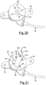
- FIG. 21 is a perspective view of an actuator showing an outer cover in the form of a rotatable body
- FIG. 22 is a perspective view of an actuator showing an outer cover in the form of a rotatable body.
- FIG. 23 is a sectional view of the actuator of FIG. 22 .
- the park lock assembly 12 is driven between its engaged and disengaged states by an electrically powered primary park lock actuator.
- the park lock assembly 12 includes a lever 16 coupled to the transmission 10 for movement between a first position in which the park lock assembly is engaged to prevent shifting the transmission out of park, and a second position in which the park lock assembly is disengaged.
- the lever 16 is coupled to a shaft 18 that, in normal vehicle operation, is driven by the primary actuator to pivot the lever among its two positions.
- the secondary park lock actuator 14 may be manually manipulated as set forth herein.
- the secondary actuator 14 may be mounted remotely from the transmission 10 and coupled thereto by a mechanical power transmission member, shown as a cable 20 .
- the cable 20 may be a push-pull or Bowden style cable to facilitate driving the park lock assembly 12 to both of its engaged and disengaged positions.
- a cable 20 has a conduit 22 fixed at both ends, such as to a bracket 24 on the transmission 10 at one end and to a housing 26 of the secondary actuator 14 or an adjacent structure at its other end.
- the cable 20 also has a core 28 ( FIGS. 2 and 3 ) slidably received for reciprocation within the conduit 22 .
- the core 28 is coupled at one end to the park lock assembly 12 , such as to the shaft 18 , and at the other end the core 28 is coupled to a drive member 30 of the secondary actuator 14 .
- the drive member 30 may be carried by or received within the housing 26 of the secondary actuator 14 .
- the housing 26 may be located in any desired position within the vehicle, such as under a vehicle hood or, as shown in FIG. 8 , behind or beneath an interior trim piece 32 for access to the secondary actuator 14 within a passenger compartment of the vehicle.
- the housing 26 may include a first portion, hereinafter referred to as the base 34 , and a second portion, hereinafter referred to as a cover 36 , that is coupled to the base at least partially enclosing the drive member 30 .
- the base 34 may include a bracket 38 to which the conduit 22 is coupled and one or more mounting features by which the housing may be secured to an adjacent structure in the vehicle.
- the mounting features includes outwardly extending flanges 40 with holes 42 to receive fasteners connecting the housing 26 to the adjacent structure.
- the bracket 38 could be formed in the base 34 , the cover 36 or partially in each of the base and cover, as well as being formed in or by another component separate from the housing 26 , as desired.
- the bottom surface 53 of the upper wall 46 may include arcuate guide tracks 55 extending from one or more of the voids 48 .
- two retainers 58 are carried by the drive member 30 , generally diametrically opposed, to balance forces across the drive member.
- the retainers 58 may extend axially from the drive member 30 for receipt in axially arranged stop features 44 , shown as voids 48 in the housing cover 36 .
- the housing 26 may include a first void 48 (or first set of voids, with one void for each retainer 58 where multiple retainers are provided) in which the retainer 58 is received in the first rotary position of the drive member 30 and a second void 48 (or second set of voids) in which the retainer 58 is received in the second rotary position of the drive member.
- the voids thus define first and second stop features engageable with the retainer(s) in the different positions of the drive member so that the second actuator 14 can be positively retained in the first position in which the park lock assembly 12 is in its engaged state, and also in the second position in which the park lock assembly is in the disengaged state.
- the direction of movement of the retainer 58 between its first and second positions is different than the direction of movement of the drive member 30 between its first and second positions.
- the retainer 58 must be moved from its first position to its second position, and then the drive member 30 may be moved from its first position to its second position, or from its second position to its first position.
- the retainer 58 is fixed to and moves with the drive member 30 .
- the drive member 30 is movable in two different directions, or along two different paths of motion, relative to the housing 26 .
- the first direction or first path of motion includes rotation about an axis 60 ( FIGS. 2, 4 and 5 )
- the second direction or second path of motion includes axial movement, which is movement parallel to or along the axis 60 .
- the first path of motion is within a plane 62 ( FIG.
- a biasing member such as a spring 64
- the drive member 30 may act on the drive member 30 (in this example) in a direction tending to axially move to or keep the retainer 58 in the first position, absent a stronger force tending to move the retainer 58 toward its second position.
- the retainer 58 must first be moved to its second position.
- the drive member 30 is first moved axially to disengage the retainer 58 from the housing 26 , and then the drive member can be rotated among and between its first and second positions.
- FIG. 9 the tool 68 is received in the tool engaging feature 66 of the drive member 30 and, via the tool, the drive member has been axially displaced to position the retainers 58 in their second position, clear of the stop features/voids 48 in the cover 36 .
- the drive member 30 is still in its first rotary position.
- FIG. 10 the drive member 30 is shown in its second rotary position, with the retainers 58 still in their second positions.
- FIG. 11 the drive member 30 is in its second rotary position and the drive member has also moved axially so that the retainers 58 /drive member 30 are in their first axial position, received within voids 48 to prevent rotation of the drive member 30 .
- FIG. 10 the drive member 30 is shown in its second rotary position, with the retainers 58 still in their second positions.
- FIG. 11 the drive member 30 is in its second rotary position and the drive member has also moved axially so that the retainers 58 /drive member 30 are in their first axial position, received within voids 48 to
- the retainers 58 are received within the first set of voids 48 and in FIG. 11 , the retainers are received within the second set of voids 48 .
- the vehicle transmission 10 may be shifted out of park moved or towed with the park lock assembly 12 disengaged, and without the secondary actuator inadvertently returning to or toward its first position in which the park lock assembly is engaged.
- the tool 68 is reinserted into the tool engaging feature 66 , the retainers 58 /drive member 30 are moved to the second axial position against the force of the biasing member 64 , and then the drive member is rotated to its first rotary position.
- the retainer 74 When the drive member 30 is fully rotated to the other position, the retainer 74 is aligned with a second opening 82 in the housing 26 and the biasing member 78 urges the retainer at least partially into the second opening 82 to retain the drive member 30 in that position. Thus, the retainer 74 is automatically reset into its first position when the drive member 30 is fully moved to either the first or second position.
- the paths of motion of the retainer 74 and the drive member 30 are parallel (e.g. within planes that are parallel to each other). Axial movement of the drive member 30 is not needed to move the retainer relative to the stop feature(s).
- the retainer shown in FIG. 12 could instead be carried by or mounted to the housing 26 , and a stop surface engaged by the retainer in its first position could be defined in or by the drive member 30 .
- the drive member 30 may include two stop surfaces that are spaced apart and arranged so that the retainer engages one stop surface in the first position of the drive member and the retainer engages the other stop surface engages in the second position of the drive member.
- the retainer 84 is radially movable to a second position, which may occur against the force of a biasing spring 87 , in which the retainer 84 is received within the housing cover 36 , that is, the retainer 84 does not radially overlap or engage the cover 36 .
- the paths of motion of the retainer 84 and drive member 30 are parallel (e.g. within planes that are parallel to each other).
- the retainer could be movable along a different path, at any angle from the housing cover 36 between a first position in which a stop feature of the housing interferes with or is engaged by the retainer upon attempted rotation of the drive member 30 , to a second position in which the housing 26 does not interfere with rotation of the drive member.
- axial movement of the drive member 30 is not necessary in this implementation, but could be used, if desired.
- the drive member 30 could also include one retainer 58 as shown in FIGS.
- Openings 94 may be provided at either end of the slot 88 and the retainer 92 may be yieldably biased outwardly to a first position so that when the retainer is aligned with an opening 94 , the retainer is urged outwardly and a portion of the retainer is received within the opening.
- the retainer 92 is pressed inwardly, to a second position, so that it is clear or sufficiently clear of the opening 94 .
- a secondary park lock actuator 96 as shown in FIG. 15 is similar to the actuator 83 shown in FIG. 13 , however, the retainer 98 is carried by the housing 26 instead of being carried by the drive member 30 .
- the stop feature 100 that the retainer 98 engages in its first position is a surface or part of the drive member 30 .
- the retainer 98 moves radially relative to the drive member 30 and housing 26 .
- the retainer 98 is moved away from the drive member 30 , and in this implementation, the retainer 98 is moved radially outwardly (relative to the drive member axis of rotation 60 ) to it second position until the retainer is out of the path of motion of the drive member.
- the stop surface 100 may be defined by an opening 101 in the drive member 30 into which the retainer 98 extends.
- the drive member 30 may include two openings 101 or stop surfaces 100 that are rotationally or circumferentially spaced apart.
- a first opening/stop surface receives or engages the retainer 98 in the first position of the drive member 30 and a second opening/stop surface receives or engages the retainer in the second position of the drive member.
- a biasing member 102 could yieldably urge the retainer 98 to or toward its first position so that the retainer automatically advances into an aligned opening 100 of the drive member 30 unless a greater force acts on the retainer. While the retainer 98 is shown as moving radially between its two positions, a retainer carried by the housing may move in any direction toward and away from the drive member 30 , as desired.
- the secondary park lock actuator 104 shown in FIG. 16 is similar to the actuator shown in FIGS. 2-11 in that the retainer 106 is carried by the drive member 30 and extends and moves axially relative to the housing 26 .
- the retainer 106 is movably carried by the drive member 30 which means that the retainer may move relative to the drive member but the retainer moves with the drive member when the drive member is moved.
- the retainer 106 is shown in its first position in FIG. 16 , interferingly engaged with a stop feature 108 (e.g. a surface) of the housing 26 to prevent rotation of the drive member 30 .
- More than one stop feature 108 may be provided, and the stop features may be defined by openings 48 in the housing cover 36 , the same as or similar to the opening 48 provided in the actuator 14 .
- the retainer 106 To rotate the drive member 30 , the retainer 106 must be axially displaced relative to the drive member 30 to a second position, clear of the housing 26 . Then, the drive member 30 can be rotated to its other position, without having to axially displace the drive member.
- a biasing member such as a spring 109 , may urge the retainer 106 toward its first position so that the retainer automatically returns to its first position when aligned with an opening 48 in the housing 26 .
- the retainer 106 could then be pulled axially away from the drive member 30 to permit rotation of the drive member, and the biasing member 109 would resist such movement. Axial movement of the drive member 30 itself is not needed in this implementation, but could be utilized or allowed to occur, if desired.
- a secondary park lock actuator 120 as shown in FIG. 17 is similar to the actuator 104 shown in FIG. 16 in that the retainer 122 is axially movable relative to the drive member 30 and also moves with the drive member 30 when the drive member is rotated.
- the drive member 30 includes a first body 124 to which the cable core 28 is connected and a second body 126 that is carried by the first body 124 and which is axially movable relative to the first body.
- the second body 126 includes or carries both the retainer 122 and the tool engaging feature 66 .
- the first body 124 includes a cavity 127 in which the complementarily or at least somewhat complementarily shaped second body 126 is slidably received.
- the bodies 124 , 126 may be radially overlapped or otherwise coupled so that they rotate together. That is, rotation of the second body 126 also causes rotation of the first body 124 .
- the first body 124 of the drive member 30 does not move in two directions, or with two distinct movements (e.g. axial and then rotary movement). Instead, the second body 126 is moved axially relative to the first body 124 to release the retainer 122 from the stop feature 128 (which may be defined by openings 48 in the housing cover 36 ). Then, the second body 126 and first body 124 are rotated together to change the position of the drive member 30 .
- an outer cover 130 may be received over all or part of the actuator housing 26 .
- the outer cover 130 surrounds the housing cover 36 and includes a tab 132 inserted into an opening 134 in the housing cover sidewall 50 , and a flange 136 that may be received within a channel or slot 138 in the base 34 to retain the outer cover 130 in position on the housing 26 .
- a tool cavity 140 in the outer cover 130 permits a portion of the outer cover 130 to be pried or otherwise outwardly displaced to remove the tab 132 from the opening 134 and allow the outer cover 130 to be removed from the housing 26 .
- the tool engaging feature 66 is then exposed and a tool 68 may be inserted therein to actuate the drive member and/or retainer.
- FIG. 19 illustrates an outer cover 150 that surrounds at least part of and up to all of the housing cover 36 , and which includes a circumferentially extending rim 152 or separate, spaced apart tabs that extend outwardly from the outer cover 150 and are overlapped by flanges 154 of the base 34 .
- the outer cover 150 may be squeezed inwardly to radially displace at last part of the rim 152 or tabs so that they are not overlapped by the flanges 154 , and the outer cover 150 can then be pulled off of the base 34 to expose the tool engaging feature 66 .
- the outer cover is defined by a plug 160 that is complementary in shape and is pressed into the tool engaging feature 66 of the drive member 30 .
- the plug 160 is pried or pulled out of the drive member 30 to permit access to the tool engaging feature 66 by a tool 68 .
- a tether 162 may be coupled to the housing 26 (e.g. the cover 36 ) at one end and to the plug 160 at its other end to facilitate pulling the plug out of the drive member 30 and to prevent the plug from becoming separated from the drive member and lost after the plug is removed from the tool engaging feature 66 .
- the outer cover 170 overlies the tool engaging feature 66 and prevents contaminants from collecting in the tool engaging feature.
- the outer cover 170 is rotatably carried by the housing, such as by a post or pin 172 received in an opening of the housing 26 , so that the outer cover 170 may be rotated away from the tool engaging feature 66 when desired.
- a stop member 176 may be movably carried by the housing 26 and in a first position the stop member 176 blocks rotation of the outer cover 170 to prevent inadvertent movement of the outer cover.
- the stop member 176 may be moved to a second position (e.g. axially pressed or otherwise displaced) to permit the outer cover 170 to be rotated away from the tool engaging feature 66 .
- a spring may be provided to yieldably bias the outer cover to its first position, such that a force is required to move the outer cover to its second position against the spring force before the tool engaging feature 66 is exposed.
- the axis of rotation 178 of the outer cover 170 may be parallel to and offset from the drive member axis of rotation 60 .
- the outer cover 180 overlies the tool engaging feature 66 and prevents contaminants from collecting in the tool engaging feature.
- the outer cover 180 is rotatably carried by the housing 26 , such as by a post or pin 182 received in an opening 184 of the housing 26 ( FIG. 23 ), so that the outer cover 180 may be rotated away from the tool engaging feature 66 when desired.
- it includes a slot or other tool engaging feature 186 by which a tool may be used to rotate the outer cover 180 to the second position wherein the tool engaging feature 66 of the drive member 30 is exposed.
- the slot or other tool engaging feature 186 may be arranged coaxially with the axis of rotation 188 of the outer cover 180 , which may be parallel to but offset from the drive member axis of rotation 60 .
- the secondary park lock actuator may be manually manipulated to change the state of the park lock assembly as desired.
- the state of the park lock assembly may be maintained in either its engaged or disengaged position by positively retaining the position of the drive member of the secondary park lock actuator in both its first and second positions. This prevents inadvertent changing of the state of the park lock assembly and allows for predictable actuation and use of the park lock assembly.
- the housing includes a first void in which a retainer is received when the drive member is in its first position, and a second void in which the retainer is received when the drive member is in its second position.
- two separate or independent movements may be required to permit changing the position of the drive member.
- a retainer carried by the drive member before the drive member can be moved from one position to the other position, a retainer carried by the drive member must be moved from a first position to a second position. Thereafter, the drive member can be moved, e.g. rotated, to displace the cable core and change the state of the park lock assembly.
- the retainer may be fixed to and not movable relative to the drive member and in other implementations, the retainer may be moved relative to the drive member.
- At least one of the retainer and the drive member moves relative to the housing in a direction different from the rotation of the drive member so that the retainer has a first position in which the retainer engages the housing to inhibit or prevent rotation of the drive member and the retainer has a second position in which the drive member may rotate relative to the housing.
Landscapes
- Engineering & Computer Science (AREA)
- General Engineering & Computer Science (AREA)
- Mechanical Engineering (AREA)
- Health & Medical Sciences (AREA)
- Oral & Maxillofacial Surgery (AREA)
- Gear-Shifting Mechanisms (AREA)
Abstract
Description
Claims (15)
Priority Applications (1)
| Application Number | Priority Date | Filing Date | Title |
|---|---|---|---|
| US16/047,222 US10865879B2 (en) | 2018-07-27 | 2018-07-27 | Secondary park lock actuator |
Applications Claiming Priority (1)
| Application Number | Priority Date | Filing Date | Title |
|---|---|---|---|
| US16/047,222 US10865879B2 (en) | 2018-07-27 | 2018-07-27 | Secondary park lock actuator |
Publications (2)
| Publication Number | Publication Date |
|---|---|
| US20200032903A1 US20200032903A1 (en) | 2020-01-30 |
| US10865879B2 true US10865879B2 (en) | 2020-12-15 |
Family
ID=69177672
Family Applications (1)
| Application Number | Title | Priority Date | Filing Date |
|---|---|---|---|
| US16/047,222 Active 2038-08-30 US10865879B2 (en) | 2018-07-27 | 2018-07-27 | Secondary park lock actuator |
Country Status (1)
| Country | Link |
|---|---|
| US (1) | US10865879B2 (en) |
Cited By (1)
| Publication number | Priority date | Publication date | Assignee | Title |
|---|---|---|---|---|
| US20260022763A1 (en) * | 2024-07-16 | 2026-01-22 | Jen-chih Liu | Vehicle electrical control apparatus with manual gear switching function |
Families Citing this family (2)
| Publication number | Priority date | Publication date | Assignee | Title |
|---|---|---|---|---|
| DE102019216851A1 (en) * | 2019-10-31 | 2021-05-06 | Zf Friedrichshafen Ag | Actuating device for a parking lock device of a motor vehicle |
| US12435789B1 (en) * | 2024-10-25 | 2025-10-07 | Kyung Chang Industrial Co., Ltd. | Device for manually releasing parking state |
Citations (12)
| Publication number | Priority date | Publication date | Assignee | Title |
|---|---|---|---|---|
| US5827149A (en) * | 1996-07-30 | 1998-10-27 | Hi-Lex Corporation | Electrically operated park lock for automatic transmission |
| US6378393B1 (en) | 2000-05-19 | 2002-04-30 | Kelsey-Hayes Company | Method and apparatus for manually shifting an electronically controlled transmission |
| US20020066623A1 (en) | 2000-12-01 | 2002-06-06 | Powrozek Bryan Daniel | Electric parking brake manual override |
| US6481556B1 (en) | 1998-08-20 | 2002-11-19 | Zf Friedrichshafen Ag | Parking lock for the automatic transmission of motor vehicles |
| US20070209903A1 (en) | 2006-03-10 | 2007-09-13 | Honda Motor Co., Ltd. | Parking lock releasing apparatus |
| US20090229388A1 (en) * | 2008-03-17 | 2009-09-17 | Lee Jeongyeop | Cable connecting apparatus of controller for air conditoner in vehicle |
| US20140326101A1 (en) | 2013-05-02 | 2014-11-06 | Kyung Chang Industrial Co., Ltd. | Cable pulling device used in parking mode manually releasing device for shift-by-wire type automatic transmission |
| US9004254B2 (en) | 2011-07-21 | 2015-04-14 | Hyundai Motor Company | Parking brake system |
| US9062752B2 (en) | 2013-04-23 | 2015-06-23 | Fca Us Llc | Park release apparatus for a transmission |
| US9139170B2 (en) | 2013-10-29 | 2015-09-22 | GM Global Technology Operations LLC | Hinge pillar assembly |
| US9423019B2 (en) | 2014-02-05 | 2016-08-23 | GM Global Technology Operations LLC | Manual park release actuator assembly |
| WO2017003481A1 (en) | 2015-07-02 | 2017-01-05 | Kongsberg Driveline Systems I, Inc. | Manual park release device for vehicle |
-
2018
- 2018-07-27 US US16/047,222 patent/US10865879B2/en active Active
Patent Citations (12)
| Publication number | Priority date | Publication date | Assignee | Title |
|---|---|---|---|---|
| US5827149A (en) * | 1996-07-30 | 1998-10-27 | Hi-Lex Corporation | Electrically operated park lock for automatic transmission |
| US6481556B1 (en) | 1998-08-20 | 2002-11-19 | Zf Friedrichshafen Ag | Parking lock for the automatic transmission of motor vehicles |
| US6378393B1 (en) | 2000-05-19 | 2002-04-30 | Kelsey-Hayes Company | Method and apparatus for manually shifting an electronically controlled transmission |
| US20020066623A1 (en) | 2000-12-01 | 2002-06-06 | Powrozek Bryan Daniel | Electric parking brake manual override |
| US20070209903A1 (en) | 2006-03-10 | 2007-09-13 | Honda Motor Co., Ltd. | Parking lock releasing apparatus |
| US20090229388A1 (en) * | 2008-03-17 | 2009-09-17 | Lee Jeongyeop | Cable connecting apparatus of controller for air conditoner in vehicle |
| US9004254B2 (en) | 2011-07-21 | 2015-04-14 | Hyundai Motor Company | Parking brake system |
| US9062752B2 (en) | 2013-04-23 | 2015-06-23 | Fca Us Llc | Park release apparatus for a transmission |
| US20140326101A1 (en) | 2013-05-02 | 2014-11-06 | Kyung Chang Industrial Co., Ltd. | Cable pulling device used in parking mode manually releasing device for shift-by-wire type automatic transmission |
| US9139170B2 (en) | 2013-10-29 | 2015-09-22 | GM Global Technology Operations LLC | Hinge pillar assembly |
| US9423019B2 (en) | 2014-02-05 | 2016-08-23 | GM Global Technology Operations LLC | Manual park release actuator assembly |
| WO2017003481A1 (en) | 2015-07-02 | 2017-01-05 | Kongsberg Driveline Systems I, Inc. | Manual park release device for vehicle |
Cited By (1)
| Publication number | Priority date | Publication date | Assignee | Title |
|---|---|---|---|---|
| US20260022763A1 (en) * | 2024-07-16 | 2026-01-22 | Jen-chih Liu | Vehicle electrical control apparatus with manual gear switching function |
Also Published As
| Publication number | Publication date |
|---|---|
| US20200032903A1 (en) | 2020-01-30 |
Similar Documents
| Publication | Publication Date | Title |
|---|---|---|
| US10865879B2 (en) | Secondary park lock actuator | |
| EP3508671B1 (en) | Electric door lock mechanism and method to override | |
| CN109798355B (en) | Transmission device for vehicle | |
| WO2015136775A1 (en) | Door latch device for vehicle | |
| US10443722B2 (en) | Device for preventing inadvertent selection of a parking lock function in a transmission | |
| US10094471B2 (en) | Manual park release system | |
| CN110159106B (en) | Hood lock device for vehicle | |
| US6945377B2 (en) | Integrated position switch/brake transmission shift interlock component | |
| US5197312A (en) | Cable connector for steering lock device | |
| EP2918873B1 (en) | Shifting device for vehicle | |
| US20170335957A1 (en) | Transmission shifter with multi-position lockout | |
| WO1998045559A1 (en) | Dual release hood latch and handle and system for operation | |
| US20230160469A1 (en) | Release device | |
| EP1378688B1 (en) | Shift locking apparatus for automatic transmission of vehicle | |
| US10443724B2 (en) | Manual park release for electronically shiftable transmissions | |
| US6568228B2 (en) | Shift lever device | |
| JP3951206B2 (en) | Shift lock device for automatic transmission | |
| JP3634411B2 (en) | Interlock device for shift lever for automatic transmission | |
| JP3625087B2 (en) | Mechanical shift lock device | |
| JPH0641873Y2 (en) | Automatic transmission shift lock device | |
| JPH0468726B2 (en) | ||
| AU2017202292B2 (en) | Key cylinder device | |
| EP0823571A2 (en) | Steering column automatic transmission shift lever | |
| JPH0738035Y2 (en) | Ignition key device for automatic transmission | |
| JPH09132047A (en) | Shift lever device for automatic transmission |
Legal Events
| Date | Code | Title | Description |
|---|---|---|---|
| AS | Assignment |
Owner name: DURA OPERATING, LLC, MICHIGAN Free format text: ASSIGNMENT OF ASSIGNORS INTEREST;ASSIGNORS:LEGAULT, DAVID;SAYEAU, JOHN;REEL/FRAME:046482/0860 Effective date: 20180725 |
|
| FEPP | Fee payment procedure |
Free format text: ENTITY STATUS SET TO UNDISCOUNTED (ORIGINAL EVENT CODE: BIG.); ENTITY STATUS OF PATENT OWNER: LARGE ENTITY |
|
| STPP | Information on status: patent application and granting procedure in general |
Free format text: NON FINAL ACTION MAILED |
|
| STPP | Information on status: patent application and granting procedure in general |
Free format text: RESPONSE TO NON-FINAL OFFICE ACTION ENTERED AND FORWARDED TO EXAMINER |
|
| STPP | Information on status: patent application and granting procedure in general |
Free format text: NOTICE OF ALLOWANCE MAILED -- APPLICATION RECEIVED IN OFFICE OF PUBLICATIONS |
|
| STPP | Information on status: patent application and granting procedure in general |
Free format text: PUBLICATIONS -- ISSUE FEE PAYMENT VERIFIED |
|
| STCF | Information on status: patent grant |
Free format text: PATENTED CASE |
|
| AS | Assignment |
Owner name: DUS OPERATING INC., MICHIGAN Free format text: ASSIGNMENT OF ASSIGNORS INTEREST;ASSIGNORS:DURA OPERATING, LLC;DURA AUTOMOTIVE SYSTEMS, LLC;DURA GLOBAL TECHNOLOGIES, INC.;AND OTHERS;REEL/FRAME:058241/0814 Effective date: 20200605 |
|
| AS | Assignment |
Owner name: BLUE TORCH FINANCE LLC, AS COLLATERAL AGENT, NEW YORK Free format text: PATENT AND TRADEMARK SECURITY AGREEMENT;ASSIGNORS:DURA AUTOMOTIVE HOLDINGS U.K., LTD;DUS OPERATING INC.;GROUPER STAMPING, LLC;AND OTHERS;REEL/FRAME:059704/0131 Effective date: 20220413 |
|
| AS | Assignment |
Owner name: GROUPER ACQUISITION COMPANY, LLC, MICHIGAN Free format text: RELEASE BY SECURED PARTY;ASSIGNOR:BLUE TORCH FINANCE LLC;REEL/FRAME:064502/0136 Effective date: 20230801 Owner name: GROUPER STAMPING LLC, MICHIGAN Free format text: RELEASE BY SECURED PARTY;ASSIGNOR:BLUE TORCH FINANCE LLC;REEL/FRAME:064502/0136 Effective date: 20230801 Owner name: DUS OPERATING INC., MICHIGAN Free format text: RELEASE BY SECURED PARTY;ASSIGNOR:BLUE TORCH FINANCE LLC;REEL/FRAME:064502/0136 Effective date: 20230801 Owner name: DURA AUTOMOTIVE HOLDINGS U.K., LTD., UNITED KINGDOM Free format text: RELEASE BY SECURED PARTY;ASSIGNOR:BLUE TORCH FINANCE LLC;REEL/FRAME:064502/0136 Effective date: 20230801 |
|
| MAFP | Maintenance fee payment |
Free format text: PAYMENT OF MAINTENANCE FEE, 4TH YEAR, LARGE ENTITY (ORIGINAL EVENT CODE: M1551); ENTITY STATUS OF PATENT OWNER: LARGE ENTITY Year of fee payment: 4 |
|
| AS | Assignment |
Owner name: ECLIPSE BUSINESS CAPITAL LLC, AS AGENT, ILLINOIS Free format text: SECURITY INTEREST;ASSIGNORS:GROUPER ACQUISITION COMPANY, LLC;DUS OPERATING INC.;GROUPER STAMPING, LLC;REEL/FRAME:067799/0694 Effective date: 20240620 |
|
| AS | Assignment |
Owner name: CERBERUS BUSINESS FINANCE AGENCY, LLC, NEW YORK Free format text: SECOND LIEN PATENT SECURITY AGREEMENT;ASSIGNORS:GROUPER ACQUISITION COMPANY, LLC;DUS OPERATING INC.;GROUPER STAMPING, LLC;REEL/FRAME:070077/0487 Effective date: 20250131 |