US10863473B2 - Methods, network, integrated circuitry and apparatus for telecommunications device location - Google Patents
Methods, network, integrated circuitry and apparatus for telecommunications device location Download PDFInfo
- Publication number
- US10863473B2 US10863473B2 US16/324,126 US201716324126A US10863473B2 US 10863473 B2 US10863473 B2 US 10863473B2 US 201716324126 A US201716324126 A US 201716324126A US 10863473 B2 US10863473 B2 US 10863473B2
- Authority
- US
- United States
- Prior art keywords
- terminal device
- positioning
- communication mode
- transmission phase
- base stations
- Prior art date
- Legal status (The legal status is an assumption and is not a legal conclusion. Google has not performed a legal analysis and makes no representation as to the accuracy of the status listed.)
- Active
Links
- 238000000034 method Methods 0.000 title claims abstract description 134
- 230000005540 biological transmission Effects 0.000 claims abstract description 79
- 238000004891 communication Methods 0.000 claims abstract description 75
- 238000005259 measurement Methods 0.000 claims description 69
- 230000007704 transition Effects 0.000 claims description 5
- 230000001360 synchronised effect Effects 0.000 claims description 4
- 230000011664 signaling Effects 0.000 description 29
- 230000007958 sleep Effects 0.000 description 8
- 238000010586 diagram Methods 0.000 description 7
- 238000012544 monitoring process Methods 0.000 description 7
- 230000004044 response Effects 0.000 description 6
- 238000012546 transfer Methods 0.000 description 6
- 230000008901 benefit Effects 0.000 description 5
- 230000001419 dependent effect Effects 0.000 description 5
- 230000000694 effects Effects 0.000 description 5
- 230000008569 process Effects 0.000 description 5
- 238000013459 approach Methods 0.000 description 3
- 230000007774 longterm Effects 0.000 description 3
- 230000000737 periodic effect Effects 0.000 description 2
- 230000009286 beneficial effect Effects 0.000 description 1
- 230000001413 cellular effect Effects 0.000 description 1
- 230000008859 change Effects 0.000 description 1
- 238000001514 detection method Methods 0.000 description 1
- 238000011161 development Methods 0.000 description 1
- 238000005516 engineering process Methods 0.000 description 1
- 230000000977 initiatory effect Effects 0.000 description 1
- 238000010187 selection method Methods 0.000 description 1
- 230000001960 triggered effect Effects 0.000 description 1
Images


Classifications
-
- H—ELECTRICITY
- H04—ELECTRIC COMMUNICATION TECHNIQUE
- H04W—WIRELESS COMMUNICATION NETWORKS
- H04W64/00—Locating users or terminals or network equipment for network management purposes, e.g. mobility management
-
- H—ELECTRICITY
- H04—ELECTRIC COMMUNICATION TECHNIQUE
- H04W—WIRELESS COMMUNICATION NETWORKS
- H04W52/00—Power management, e.g. TPC [Transmission Power Control], power saving or power classes
- H04W52/02—Power saving arrangements
- H04W52/0209—Power saving arrangements in terminal devices
-
- H—ELECTRICITY
- H04—ELECTRIC COMMUNICATION TECHNIQUE
- H04W—WIRELESS COMMUNICATION NETWORKS
- H04W52/00—Power management, e.g. TPC [Transmission Power Control], power saving or power classes
- H04W52/02—Power saving arrangements
- H04W52/0209—Power saving arrangements in terminal devices
- H04W52/0212—Power saving arrangements in terminal devices managed by the network, e.g. network or access point is master and terminal is slave
- H04W52/0216—Power saving arrangements in terminal devices managed by the network, e.g. network or access point is master and terminal is slave using a pre-established activity schedule, e.g. traffic indication frame
-
- H—ELECTRICITY
- H04—ELECTRIC COMMUNICATION TECHNIQUE
- H04W—WIRELESS COMMUNICATION NETWORKS
- H04W76/00—Connection management
- H04W76/20—Manipulation of established connections
- H04W76/27—Transitions between radio resource control [RRC] states
-
- Y—GENERAL TAGGING OF NEW TECHNOLOGICAL DEVELOPMENTS; GENERAL TAGGING OF CROSS-SECTIONAL TECHNOLOGIES SPANNING OVER SEVERAL SECTIONS OF THE IPC; TECHNICAL SUBJECTS COVERED BY FORMER USPC CROSS-REFERENCE ART COLLECTIONS [XRACs] AND DIGESTS
- Y02—TECHNOLOGIES OR APPLICATIONS FOR MITIGATION OR ADAPTATION AGAINST CLIMATE CHANGE
- Y02D—CLIMATE CHANGE MITIGATION TECHNOLOGIES IN INFORMATION AND COMMUNICATION TECHNOLOGIES [ICT], I.E. INFORMATION AND COMMUNICATION TECHNOLOGIES AIMING AT THE REDUCTION OF THEIR OWN ENERGY USE
- Y02D30/00—Reducing energy consumption in communication networks
- Y02D30/70—Reducing energy consumption in communication networks in wireless communication networks
Definitions
- the present disclosure relates to apparatus and methods for the location of telecommunications devices.
- Mobile telecommunications systems such as those based on the 3GPP defined UMTS and Long Term Evolution (LTE) and Long Term Evolution Advance (LTE-A) architectures, are applicable to communications between networked user devices such as mobile telephones, and more widely also to applications such as the Internet of Things (IoT), including enhanced machine type communications (eMTC) and the narrowband Internet of Things (NB-IoT).
- IoT Internet of Things
- eMTC enhanced machine type communications
- NB-IoT narrowband Internet of Things
- device positioning is of interest, allowing devices to be tracked, but this is of particular relevance to IoT devices.
- such devices are preferably low cost, have good power efficiency and are able to operate with extended coverage, such as within building basements.
- Positioning techniques which have been considered for IoT devices (but which are also applicable to other devices in a telecommunications network) include Observed Time Difference of Arrival (OTDOA) and Uplink Time Difference of Arrival (UTDOA).
- OTDOA Observed Time Difference of Arrival
- UTDOA Uplink Time Difference of Arrival
- the device measures time differences in the arrival at the device of downlink signals from a reference base station and one or more target base stations. These measurements are transmitted to a location server, which performs triangulation to calculate the device's position using the time difference measurements and the known locations of the base stations.
- UTDOA a related but opposite arrangement is used, in which the device transmits an uplink signal to multiple base stations. The base stations each measure the arrival time of this signal, which will differ according to the relative position of the device to each base station. The timings are sent to a location server which again calculates the device's position using triangulation.
- the device sends or receives the timing signals in a fully connected mode, which has high power consumption and consequent detriment to device battery life.
- the present disclosure can help address or mitigate at least some of the issues discussed above.
- FIG. 1 shows a schematic representation of an example mobile telecommunications network or system
- FIG. 1A shows a schematic representation of an example user equipment for use in a network such as the FIG. 1 example
- FIG. 1B shows a schematic representation of an example base station for use in a network such as the FIG. 1 example
- FIG. 2 shows a schematic representation of base stations and user equipment participating in an example method of determining the position of the user equipment
- FIG. 3 shows example resource element locations for signals sent by a base station such as that in FIG. 2 ;
- FIG. 4 shows a schematic representation of example radio frames incorporating positioning signals sent by base stations such as those in FIG. 2 ;
- FIG. 5 shows a schematic representation of base stations and user equipment participating in a further example method of determining the position of the user equipment
- FIG. 6 shows a signalling diagram of steps in an example method for determining the position of a user equipment
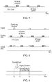
- FIG. 7 shows a time line of an example of discontinuous reception operation of a user equipment
- FIG. 8 shows a time line of an example of modified discontinuous reception operation of a user equipment
- FIG. 9 shows a time line of an example paging occasion during discontinuous reception operation of a user equipment
- FIG. 10 shows a time line of a further example of modified discontinuous reception operation of a user equipment
- FIG. 11 shows a signalling diagram of steps in a further example method for determining the position of a user equipment.
- FIG. 12 shows a signalling diagram of steps in a still further example method for determining the position of a user equipment.
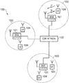
- FIG. 1 shows a schematic diagram illustrating some basic functionality of a mobile (cellular, wireless) telecommunications network/system, in this example operating generally in accordance with LTE principles, and which may be adapted to implement embodiments of the disclosure as described further below.
- Various elements of FIG. 1 and their respective modes of operation are well-known and defined in the relevant standards administered by the 3GPP® body, and also described in many books on the subject, for example, Holma, H. and Toskala, A. [1]. It will be appreciated that operational aspects of the telecommunications network which are not specifically described below may be implemented in accordance with any known techniques, for example according to the relevant standards and known variations thereof.
- the network 100 in FIG. 1 includes a plurality of base stations 101 connected to a core network 102 .
- Each base station provides a coverage area or cell 103 within which data can be communicated to and from terminal devices or user equipment 104 .
- Data is transmitted from base stations 101 to user equipment 104 within the respective coverage areas 103 via a radio downlink DL.
- Data is transmitted from user equipment 104 to the base stations 101 via a radio uplink UL.
- the uplink and downlink communications are made using radio resources that may be used by the operator of the network.
- the core network 102 routes data to and from each user equipment 104 via the respective base stations 101 and provides functions such as authentication, mobility management, charging and so on.
- the system may further comprise one or more relay nodes/devices (not shown), which may be used to enhance coverage for user equipment operating in the relevant cell(s).
- the deployment of relay nodes may follow generally established techniques for using relay nodes to support coverage in wireless telecommunications systems by assisting downlink and/or uplink communications.
- terminal devices may also be referred to as mobile stations, user equipment (UE), user terminal, terminal, mobile radio, mobile terminal, mobile device, or simply device, and so forth.
- Base stations may also be referred to as transceiver stations, nodeBs, e-nodeBs, eNBs and so forth.
- Mobile telecommunications systems such as those arranged in accordance with the 3GPP defined Long Term Evolution (LTE) architecture use an orthogonal frequency division multiplex (OFDM) based interface for the radio downlink (so-called OFDMA) and the radio uplink (so-called SC-FDMA).
- OFDM orthogonal frequency division multiplex
- FIG. 1A shows a schematic representation of an example of a user equipment 104 .
- the user equipment 104 comprises a transceiver unit 104 A for transmission and reception of wireless signals and a processor unit 104 B configured to control the user equipment.
- the processor unit 104 B may comprise various sub-units for providing functionality in accordance with embodiments of the present disclosure as explained further herein. These sub-units may be implemented as discrete hardware elements or as appropriately configured functions of the processor unit.
- the processor unit 104 B may comprise a processor unit which is suitably configured/programmed to provide the desired functionality described herein using conventional programming/configuration techniques for equipment in wireless telecommunications systems.
- the transceiver unit 104 A and the processor unit 104 B are schematically shown in FIG.
- the functionality of these units can be provided in various different ways, for example using a single suitably programmed general purpose computer, or suitably configured application-specific integrated circuit(s)/circuitry.
- the user equipment 104 will in general comprise various other elements associated with its operating functionality, for example a power source, user interface, and so forth, but these are not shown in FIG. 1A in the interests of simplicity.
- FIG. 1B shows a schematic representation of an example of a base station 101 .
- each base station 101 may be functionally identical but each serves a different geographical area (cells 103 ).
- Each base station 101 comprises a transceiver unit 101 A for transmission and reception of communications between the base station and any user equipment 104 in its cell, and the core network 102 .
- a base station 101 further comprises a processor unit 101 B configured to control the base station 101 to operate in accordance with embodiments of the present disclosure as described herein.
- the processor unit 101 B may again comprise various sub-units for providing functionality in accordance with embodiments of the present disclosure as explained herein. These sub-units may be implemented as discrete hardware elements or as appropriately configured functions of the processor unit.
- the processor unit 101 B may comprise a processor unit which is suitably configured/programmed to provide the desired functionality described herein using conventional programming/configuration techniques for equipment in wireless telecommunications systems.
- the transceiver unit 101 A and processor unit 101 B are schematically shown in FIG. 1B as separate elements for ease of representation.
- the functionality of these units can be provided in various different ways, for example using a single suitably programmed general purpose computer, or suitably configured application-specific integrated circuit(s)/circuitry.
- the base station 101 will in general comprise various other elements, for example a power supply, associated with its operating functionality.
- RRC Radio Resource Control
- a terminal device in addition to the device being wholly unconnected to the network (for example when the device is switched off), it is common to support an RRC idle mode and an RRC connected mode.
- RRC connected mode a terminal device is connected to a base station in the sense of being able to receive user plane data from the base station, whereas in RRC idle mode the terminal device is unconnected to a base station in the sense of not being able to receive user plane data from the base station.
- the terminal device may still receive some communications from base stations, for example reference signalling for cell reselection purposes and other broadcast signalling.
- the core network (CN) part of the wireless telecommunications system recognizes that the terminal device is present within the network, but the radio access network (RAN) part of the wireless telecommunications system (i.e. comprising the base stations) does not.
- the terminal device in RRC idle mode the terminal device is not connected to a base station, whereas in RRC connected mode the terminal device is connected/attached to a base station.
- the RRC connection setup procedure of going from RRC idle mode to RRC connected mode may be referred to as connecting to a cell/base station.
- radio resource control states may be defined for the terminal to have a full connection or a limited connection with a base station.
- a “full” connection or a terminal being “fully” connected (or simply “connected”) with a base station refers to a radio resource control (e.g. RRC in 3GPP) state or mode in which the terminal can (among other functions) exchange user data and signalling with a base station.
- a “limited” or idle connection refers to a radio resource control state or mode in which the terminal cannot exchange user data with a base station, but still retains some communications functionality.
- the terminal may be configured to do one or more of: monitoring and receiving paging information, carrying out measurements, handling mobility (e.g. to another cell), and the like.
- the terminal may be able to receive data in a broadcast manner such as by MBMS (Multimedia Broadcast Multicast Services) or eMBMS (evolved MBMS).
- MBMS Multimedia Broadcast Multicast Services
- eMBMS evolved MBMS
- One characteristic of the RRC connected mode is the allocation of a cell-specific radio network temporary identifier (C-RNTI) to the terminal device to allow the base station to which the terminal device is connected to address communications to the terminal device.
- C-RNTI cell-specific radio network temporary identifier
- RRC connected mode Another characteristic of the RRC connected mode is the association of one or more dedicated logical channels with the terminal device to allow the terminal device to exchange data with the base station to which it is connected.
- a terminal device in a conventional RRC idle mode will not be associated with this kind of dedicated logical communication channel.
- RRC connected mode Another characteristic of the RRC connected mode is that a terminal device in RRC connected mode will have established a security context by exchanging security settings with the base station to which it is attached as part of its RRC connection procedure. A terminal device in a conventional RRC idle mode will not have this kind of established security context.
- a base station to which a terminal device is connected in RRC connected mode will retain information relating to the terminal device, for example its allocated C-RNTI, logical channel configuration settings, security settings, and so on, to allow the base station to communicate with the terminal device.
- This information may generally be referred to as a terminal device context in/at the base station.
- the base station releases the terminal device context when a terminal device releases its RRC connection with respect to a particular base station and transitions to conventional RRC idle mode.
- a terminal device Whilst in RRC idle mode a terminal device will receive signalling from base stations covering its location (i.e. base stations within radio signalling range of its location), for example reference signalling and other broadcast signalling. Based on this signalling the terminal device is able to determine what is currently the most appropriate base station to connect to were the terminal device required to establish a connection to the network, for example to transmit uplink data or in response to a paging request. This ongoing procedure/process for determining the most appropriate base station to connect to is known as cell selection/reselection.
- the terminal device will synchronise to a selected base station and decode relevant broadcast information, for example information transmitted in master information block (MIB) and system information block (SIB) transmissions, from the selected base station so the terminal device is able to initiate a radio resource connection with the selected base station as and when appropriate.
- relevant broadcast information for example information transmitted in master information block (MIB) and system information block (SIB) transmissions, from the selected base station so the terminal device is able to initiate a radio resource connection with the selected base station as and when appropriate.
- MIB master information block
- SIB system information block
- a terminal device operating in an RRC idle mode wishes to transition to an RRC connected mode to exchange data with the network, it transmits an RRC connection request message to the currently selected base station to initiate an RRC connection procedure in accordance with well-established techniques.
- RRC connection request message In association with the RRC connection procedure, signalling is exchanged between the terminal device and the base station to allow the base station to establish a context for the terminal device to support subsequent communications in the RRC connected mode, for example to exchange information relating to a C-RNTI for the terminal device, dedicated logical channel configuration settings, and security settings.
- RRC idle mode can be beneficial for a terminal device, for example in terms of power saving.
- a drawback of switching to RRC idle is the signalling overhead associated with establishing a new RRC connection when the terminal device is required to reconnect to a base station and exchange data with the base station to allow the base station to establish a context for the terminal device.
- This signalling overhead has an impact for the terminal device in terms of using power and also for the wireless telecommunications network as a whole in terms of taking up radio resources that might otherwise be used for other communications. Consequently, there is typically a compromise to be made between entering RRC idle mode frequently (to preserve terminal device power) and remaining in RRC connected mode for longer periods (to reduce re-connection signalling overhead).
- the terminal device may be considered to be in a mode in which its RRC connection to a base station is suspended, as opposed to the connection being released as with conventional idle mode.
- the RRC suspend mode may be considered to correspond to a special case of the RRC idle mode.
- the terminal device when a terminal device in the RRC suspend mode wishes to re-establish a connection to a currently selected base station (i.e. selected in accordance with the terminal device's conventional cell (re)selection procedures), the terminal device transmits signalling corresponding to a RRC Connection Resume Request to the selected base station. Because the terminal device may have undergone a cell reselection while in the RRC suspend mode (e.g. due to mobility), it may seek to resume connection with a base station which is different from the base station to which the terminal device was previously connected (i.e. the base station storing the terminal device context information).
- the base station to which the terminal device is seeking to connect might not itself have a record of the relevant context information for the terminal device. Accordingly, it has been proposed for a terminal device requesting resumption of an RRC connection to provide an indication of the base station storing its context information (i.e. the base station to which the terminal device was connected before its RRC connection was suspended). In particular, it has been proposed that a terminal device seeking to re-establish connection to the network via a selected base station should convey an indication of what is referred to as a Resume ID.
- the Resume ID includes an indication of both the identity of the terminal device and the identity of the base station storing the terminal device's context information.
- the terminal device or UE when an RRC connection is suspended, the terminal device or UE stores a Resume ID and then transitions into what is otherwise an RRC idle state.
- the network Upon indication from the lower protocol layers that the RRC connection has been suspended, the network enters EMM (evolved packet system mobility management) idle mode with suspend indication, but does not consider the NAS signalling connection released. Then, in a message to resume, the UE provides the Resume ID to be used by a selected eNB to access the stored information required to resume the RRC connection.
- RRC configures the UE according to the RRC connection resume procedure based on the stored UE context and any RRC configuration received from the network.
- the RRC connection resume procedure re-activates security and re-establishes the usual connection radio bearers.
- the network Upon indication from the lower layers that the RRC connection has been resumed when in EMM idle mode with suspend indication, the network enters EMM connected mode.
- the suspend/resume procedure re-establishes radio bearers and continues security, the overhead of performing a full RRC Connection establishment procedure (from idle mode to connected mode) may be avoided. Thereby, the RRC signalling overhead when moving between RRC idle and RRC connected modes is reduced.
- RRC connected mode requires the exchange of a large amount of signals, for purposes such as the monitoring of control channels such as MPDCCH and NPDCCH. Accordingly, RRC connected mode operation can consume significantly more power than operation in an RRC idle mode or an RRC suspended mode. Consequently, in the context of the present disclosure, RRC idle and RRC suspended modes can be thought of as energy saving modes or low energy modes, as compared to an RRC connected mode, which is a high energy mode. Also, a mode using Discontinuous Reception (DRX) in which a long cycle time is employed can also be used as an energy saving mode, since most of the time the UE is asleep, and wakes up only periodically in time with the DRX cycle.
- DRX Discontinuous Reception
- RSTD Reference Signal Time Difference
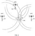
- FIG. 2 shows a schematic representation of this procedure.
- a UE 104 receives a signal from each of three eNBs 101 , one of which is designated as the reference eNB, and notes the time at which each signal arrives. Then, the difference in arrival time for the signal from each eNB compared to the arrival time from the reference eNB is determined; this is the RSTD.
- the accuracy of the position calculated for the UE is dependent upon the accuracy of the measured RSTD, which is turn depends on the accuracy of the measured arrival times. For example, in the FIG.
- the time of arrival from eNB 1 has an accuracy of ⁇ T 1 (being the error between the earliest and latest possible arrival times)
- the time of arrival from eNB 2 has an accuracy of ⁇ T 2
- the time of arrival from eNB 3 has an accuracy of ⁇ T 3 .
- This accuracy of the time of arrival measurement depends on the quality of the measured signal (a reference signal) and the bandwidth of that reference signal.
- the arrival times at the UE can be estimated using an existing signal, for example reference signals such as CRS (cell-specific reference signal), PSS (primary synchronisation signal) or SSS (secondary synchronisation signal).
- reference signals such as CRS (cell-specific reference signal), PSS (primary synchronisation signal) or SSS (secondary synchronisation signal).
- CRS cell-specific reference signal
- PSS primary synchronisation signal
- SSS secondary synchronisation signal
- PRS dedicated Positioning Reference Signals
- FIG. 3 shows examples of resource element locations of a set of PRS for an eNB; the location occupied is dependent upon the eNB's Cell ID.
- the N PRS consecutive subframes of PRS transmission are known as a Positioning Occasion.
- FIG. 4 shows an example of a sequence of transmitted radio frames incorporating PRS.
- Each radio frame is made up of ten subframes ( 0 to 9 ).
- the Positioning Occasion does not occur in every radio frame, but is repeated with a period T PRS .
- an OTDOA procedure starts with a network component such as a location server (the network serving mobile location centre (eSMLC)) requesting through the LPP layer (a LTE positioning protocol layer) an OTDOA measurement, requiring a set of RSTD measurements from a UE.
- a network component such as a location server (the network serving mobile location centre (eSMLC)) requesting through the LPP layer (a LTE positioning protocol layer) an OTDOA measurement, requiring a set of RSTD measurements from a UE.
- the assistance data includes a list of cells (eNBs) with their PRS parameters, including bandwidth, periodicity and the like.
- the UE then proceeds to perform these measurements, by estimating the exact time offsets between the PRS from different eNBs, during a given period of time, which may typically be up to eight or 16 periods of the PRS signals.
- the UE then reports to the location server these estimated time differences together with an estimate of the measurement quality.
- the eSMLC uses the measurements together with its knowledge of the eNBs (positions and PRS transmit time offsets) to estimate the position of the UE.
- positions and PRS transmit time offsets In the context of LTE, details of the LPP can be found in the 36.355 specification, details of PRS signals can be found in section 6.10.4 of the 36.211 specification, and an example OTDOA procedure appears in section 9 of the 37.571-1 specification.
- OTDOA As described above is performed when the UE is in RRC connected mode since a connection is required between the location server and the UE.
- a UE in RRC connected mode consumes significantly more power than one in RRC idle mode, because in RRC connected operation the UE has to monitor for downlink transmission on the MPDCCH/NPDCCH control channels. Consequently, significant energy may be required to perform OTDOA.
- a further positioning technique is Uplink Time Difference Of Arrival (UTDOA).
- a UE transmits an uplink pilot signal such as a SRS (Sounding Reference Signal) that is received by multiple eNBs.
- SRS Sounding Reference Signal
- FIG. 5 shows a schematic representation of an example UTDOA procedure.
- a location server initiates the procedure by requesting a position measurement for the UE 104 .
- an SRS uplink pilot signal
- eNB 1 , eNB 2 and eNB 3 receive the SRS at times ⁇ 1 , ⁇ 2 and ⁇ 3 respectively.
- the eNBs 101 each determine their own time of arrival of the SRS, and send these timings to a location server.
- the location server uses these measured timings to calculate the UE location based on triangulation.
- Transmission of SRS by a UE is configured by an eNB in RRC connected mode, where typically in this mode, large data transfer is expected.
- UEs are not expected to perform large data transfer but rather to transfer small amounts of data infrequently.
- maintaining a UE in a connected mode that is otherwise not needed solely for the purpose of positioning would consume UE battery life due to the high power consumption in RRC connected mode (from monitoring of control channels such as M-PDCCH and NPDCCH).
- both the conventional OTDOA and UTDOA positioning methods tend to require undesirably large levels of power consumption, reducing the battery life of UEs. Accordingly, it is proposed to carry out device positioning and the measurements required therefor using an energy-saving or low energy connection mode, in place of the conventional RRC connected mode.
- the UE may be in a RRC idle mode or a RRC suspended mode during the measurement procedure.
- OTDOA uses PRS signals sent from the eNBs and received by the UE
- UTDOA uses SRS or other pilot uplink signals sent from the UE and received by the eNBs.
- these signals may collectively be termed “positioning signals”, and the time period during which these positioning signals are sent and received, which is when the UE is participating in a measurement phase of the positioning method, is performed by the UE in an energy-saving mode.
- This phase may also be considered as a transmission phase, during which the positioning signals are transmitted between the UE and the eNB (in either direction, depending on the method).
- Various configurations are envisaged for the OTDOA and UTDOA alternatives. Firstly, we consider OTDOA in detail.
- the UE performs the RSTD measurements (recall that this is the measurement of arrival time differences for PRS transmissions from multiple eNBs) in an energy saving mode, such as RRC idle or RRC suspended.
- the UE operates a discontinuous receive (DRX) arrangement, checking for paging messages once every DRX cycle, and the DRX cycle period can be long.
- DRX discontinuous receive
- the UE moves to RRC connected mode so as to be able to transmit a report of the positioning (RSTD) measurements to the location server.
- PRS positioning occasion
- T PRS is long
- UE traffic may be infrequent (for example if the UE is an MTC) and consist of small packets only.
- the UE does not need to be connected for long periods of time (since the activity that requires connection is short and infrequent), and the UE is inactive most of the time when obtaining the PRS measurements.
- use of an energy saving radio resource mode for OTDOA enables the UE to sleep (that is, use of DRX) when obtaining the PRS measurements.
- OTDOA requires only downlink activity (transmission from eNB to UE), with uplink activities (such as timing advance and power control) being unnecessary for an accurate measurement of the PRS and calculation of the RSTD.
- positioning according to such a method would be useful for network-triggered aperiodic positioning reports, such as a dog owner requesting the location of his dog to which a UE is attached; this request would trigger a positioning report from the UE.
- the method is applicable to periodic positioning reporting if the time period between reports is large (for example of the order of a couple of seconds).
- the energy saving mode for OTDOA may be RRC suspended mode, as described above.
- LTE Long Term Evolution
- anchor eNB the last eNB to which the UE was connected before being suspended.
- Paging is performed within the RAN in order to make the RRC state transition to idle mode transparent to the core network. If the UE has moved to another cell, the RAN takes care of locating the UE via paging and transferring the UE context to the new eNB. Importantly, this would enable the UE power saving state in RAN to be transparent to the core network and the LPP server (location protocol), avoiding impact to LPP signalling procedures if positioning measurements are performed in the suspended state.
- LPP server location protocol
- the UE should be provided with necessary information to enable it to carry out the required functions for a positioning method, in particular the sending or receiving of positioning signals.
- this includes measurement of the incoming positioning signals, calculation of the RSTD and report of the RSTD values to the network.
- the functions include transmission of outgoing positioning signals. Providing the UE with the required information and parameters can be considered as configuration of the UE.
- the UE can be configured for positioning measurement and reporting while it is connected to the network.
- the UE can then move into the suspended mode, when it may perform PRS measurements. It should be appreciated that the UE is not required to move immediately to suspended mode once it has been configured for positioning measurements; rather the UE can perform user data transfer in connected mode prior to moving to the suspended mode.
- the UE can also perform PRS measurement in the connected mode as per conventional OTDOA if the data transfer period overlaps a Positioning Occasion.
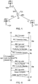
- FIG. 6 shows a schematic representation of steps in an example implementation, in the form of a signalling diagram.
- the UE establishes a RRC connection with an eNB in the network. This follows the usual steps of a RRC connection request sent from the UE to the eNB, RRC connection setup information signalling being sent from the eNB to the UE in reply to the request, and an acknowledgement that the RRC connection setup is complete sent from the UE back the eNB.
- the eNB configures the positioning parameters required by the UE for RSTD measurements, and sends them to the UE so that the UE is configured for positioning measurement and reporting (step 6 b ).
- the parameters may include the N PRS and T PRS parameters and notification of neighbouring eNBs.
- the UE may then also use its connected state to perform user data exchange but in this example, the eNB sends the UE directly into the suspended mode, in step 6 c.
- the UE stores the Resume ID, and the eNB retains the UE context.
- the UE wakes up during Positioning Occasions to perform PRS measurements (step 6 d ).
- the UE requests for its RRC connection to be resumed, including providing the Resume ID to the eNB.
- the eNB resumes the RRC connection with the UE, either by directly using the stored UE context or by transferring the UE context to another eNB into whose cell the UE has moved while suspended.
- the UE acknowledges to the eNB that the RRC connection resume is complete.
- the UE uses the RRC connection to submit the RSTD measurements to the network, by sending a positioning report to the eNB.
- this is one example of signalling to achieve OTDOA in an energy saving mode, and other signalling, for example including providing positioning configuration to the UE at the RRC Connection Setup Complete message, is possible.
- the use of a suspended mode for performing the PRS measurements is useful in that the RRC connection required for the UE to transmit the positioning report can be implemented more readily (with lower signalling overhead) than if the UE is in a full RRC idle mode.
- the positioning configuration may instead be broadcast in the system information.
- a UE can receive system information in the form of Master Information Blocks (MIB) and/or System Information Blocks (SIB) while in RRC idle mode (or RRC suspended mode), for the purpose of obtaining parameters necessary for functions including cell selection, paging message detection and network access, and the OTDOA configuration information can be included also.
- MIB Master Information Blocks
- SIB System Information Blocks
- RRC idle mode or RRC suspended mode
- This option saves the requirement for the UE to be in RRC connected mode for positioning configuration.
- Additional configuration if required, can then be configured at a time when the UE is RRC connected.
- An indication can be signalled to the UE to start the PRS measuring process. Such an indication can be signalled in a RRC message.
- a UE that has been preconfigured with positioning configurations is indicated when it is in idle mode to start the PRS measurement.
- This indication can be done via paging where the said indication can be included in the DownLink Control Information (DCI), or in a paging message.
- DCI DownLink Control Information
- the UE can search for its ID in the paging message. Once the indication is made, the UE can perform a RRC Connection to setup the security and obtain further PRS configuration such as assistance information to help the UE in PRS measurement, and then move to suspended mode to perform the PRS measurement as described above.
- the DCI or paging message can directly instruct the UE to perform PRS measurements without performing an RRC connection.
- the UE is not preconfigured in any way, all the positioning configuration parameters may be provided to the UE once it enters RRC connection mode in response to the positioning indication.
- a UE in suspended mode may be paged to perform PRS measurements.
- the paging message may contain positioning configurations, so the UE need not be preconfigured. Also, if the paging message contains all positioning configurations, the UE does not need to resume its RRC connection for further or updated configuration, and can proceed directly to PRS measurement. However, if the paging message includes only partial positioning configurations, the UE can enter RRC connected mode to obtain further configuration as above.
- a UE that has been preconfigured with positioning configurations is notified while in RRC connected mode to start PRS measurements. This may be via a DCI carried by an NPDCCH or MPDCCH, for example. The UE can then release its connection and move to suspended mode to perform the PRS measurements.
- the UE After the PRS measurements have been made and the RSTD values obtained, the UE needs to report the results to the network for the positioning triangulation calculation. Triggering of the reporting may be achieved in a variety of ways. For example, the UE may stop obtaining PRS measurements and resume its RRC connection to submit its positioning report when it has obtained a predefined number of RSTD measurements. This predefined number might be notified to the UE as a parameter in the positioning configuration, for example, or may be a function of the number of eNBs to be included in the PRS measurements which the UE determines when the OTDOA is initiated.
- the UE may stop obtaining PRS measurements and resume its RRC connection to submit its positioning report after a predefined period of time.
- This predefined period of time may be configured by the network as part of the positioning configuration provided to the UE, for example.
- the UE may stop obtaining the PRS measurements and resume its RRC connection to submit its positioning report when it is paged by the network. In other words, the UE will continue to perform PRS measurements until it is paged to submit the positioning report.
- the energy saving mode for OTDOA may be RRC idle mode, as described above, rather than RRC suspended mode. This may be implemented in various ways, depending on the mode of the UE at the time when OTDOA is required. If the UE is in RRC connected mode at this time, the RRC connection can be utilised to configure the UE, in that the PRS configuration is performed using unicast RRC messages. Alternatively configuration may be via the SIB. An indication to start the PRS measurements can be signalled in a RRC message, or in DCI. Once configured and notified to commence the OTDOA process, the UE can then move to the idle mode to perform the PRS measurements. For example, this may be done after a predefined period of time from the last user data transfer (over the RRC connection) or immediately after receipt of the starting indication (notification).
- the UE can establish an RRC connection to the eNB and move to connected mode to obtain the PRS positioning configuration. The UE can then be indicated to start PRS measurements, which prompts it to move back to RRC idle mode to perform the measurements.
- the positioning configuration can be performed using a paging message (which may include the UE ID), or indicated in the SIB. Once configured in any of these ways, the UE is then prompted to start PRS measurements using a paging message or a DCI. Once configured and prompted by an indication to perform OTDOA, the UE moves to idle mode to carry out the PRS measurements.
- the PRS measurement may be halted according to any of the previously described embodiments for triggering positioning reporting. Then, again as before, the UE performs RRC connection to submit its positioning report to the network.
- the RRC connection provides security to send the positioning report.
- the said energy saving mode for OTDOA may be an RRC connected mode operating with a long Discontinuous Reception (DRX) cycle period.
- DRX Discontinuous Reception
- the UE moves out of this long DRX to submit the positioning report using the RRC connection.
- Discontinuous Reception is a communication method intended to conserve device battery life by having the UE operate to check for paging messages only at specified phases (the DRX cycle), between which the UE switches off its receiver and enters a low power state.
- a default DRX cycle is broadcast in a System Information Block, but an individual UE may propose its own DRX cycle length.
- a long cycle time may be 256 radio frames, corresponding to 2560 ms. Note that DRX can be used in connected and idle modes.
- the UE is put into a long DRX in which the UE wakes up periodically to monitor for possible paging or grant.
- FIG. 7 illustrates this arrangement on a time line.
- the DRX cycle comprises periods of UE sleep (low power) interspersed with periods of UE wake-up activity (higher power).
- the DRX cycle time or period is the length of time from the start of one wake-up period to the next.
- the wake-up periods are Paging Occasions, and all have the same duration (note that different UEs may have wake-up periods of different duration, however), as do the sleep periods, with the wake-up period duration being significantly shorter than the sleep period.
- One sleep period plus one wake up period defines the DRX cycle time.
- the start time for a UE wake-up period will be dependent upon the UE ID, and hence the UEs in a cell wake up at different times; this allows the eNB to spread the traffic load more uniformly over time.
- the Positioning Occasion of the PRS used for OTDOA (see FIG. 4 ) is broadcast at a fixed time that is independent of any UE ID.
- the UE may be asleep during a Positioning Occasion if this does not coincide with a DRX wake-up period. Recognising this, in an embodiment an additional DRX mode is proposed, designated as Positioning DRX or P-DRX, and introduced in the said energy saving mode.
- FIG. 8 shows a time line of this modified DRX arrangement.
- the P-DRX is arranged so as to provide a UE wake-up period that coincides or overlaps with each PRX Positioning Occasion.
- Time line (a) shows this, with periodic wake-up periods (depicted as light shaded blocks) happening at the same time as the PRS is broadcast in its Positioning Occasions.
- the P-DRX are separated by the T PRS cycle time.
- the UE wakes up during Positioning Occasions to measure the PRS and sleeps in between Positioning Occasions.
- Time line (b) shows the existing DRX cycle previously shown in FIG.
- the UE wakes up to check for paging messages during Paging Occasions (darker shaded blocks).
- two DRX patterns for the UE are created, one being the energy saving mode existing DRX (e.g. Paging Occasion), and another the P-DRX.
- the resultant overall combined DRX pattern is shown in time line (c), and is the superposition of the existing DRX and P-DRX.
- the UE wakes up based on the two criteria of PRS and paging to perform one of two different tasks according to the current wake-up period, that is, to monitor for paging in a DRX wake-up period and to measure PRS in a P-DRX wake up period.
- the cycle period for DRX and P-DRX may be different and the start times for the two sets of wake-up periods are unrelated, so the duration of sleep periods is no longer constant.
- the addition of the P-DRX produces a modified DRX for use in a positioning method.
- FIG. 9 shows a time line of a DRX Paging Occasion of a UE, where the Paging Occasion starts at time ⁇ 1 and ends at time ⁇ 2 .
- the UE may need to wake up prior to its Paging Occasion, at earlier time ⁇ 0 , so as to have a “downlink sync” period between ⁇ 0 and ⁇ 1 in which to synchronise in the downlink in order to be ready and able to monitor for possible paging indications between times ⁇ 1 and ⁇ 2 .
- Performing downlink synchronisation consumes additional energy, however. Recognising this, in another embodiment, it is proposed that the UE's DRX cycle may be shifted such that its wake-up time for a Paging Occasion is adjacent or close to that of the Positioning Occasion so that the UE still maintains synchronisation when monitoring for paging and measuring PRS.
- FIG. 10 shows a time line illustrating this arrangement over several combined DRX cycles.
- the DRX cycle comprising the Paging Occasions (in idle or suspended mode), which is based on the UE ID, is shifted in time so that the Paging Occasions occur immediately before the Positioning Occasions (the PRS broadcast times are fixed so the P-DRX cycle cannot be shifted).
- a Paging Occasion end time coincides with a Positioning Occasion start time to give a longer combined wake-up period comprising a Paging Occasion plus a Positioning Occasion, plus a downlink sync period before each Paging Occasion.
- the number of downlink sync decodes required is reduced since the UE needs only a single downlink sync in order to both monitor in its Paging Occasion and measure PRS in the Positioning Occasion, rather than a downlink sync for each Paging Occasion and another down link sync for each Positioning Occasion.
- the P-DRX signal is broadcast less frequently than the paging messages, so that the DRX cycle period is half the length of the P-DRX cycle period. Hence, only every other Paging Occasion has a Positioning Occasion attached to it.
- n may be 1, 2, 3 or larger integers.
- a Positioning Occasion may occur before a Paging Occasion, rather than afterwards as in FIG. 10 .
- the Positioning Occasion and the Paging Occasion need not be immediately adjacent in time, and may instead be spaced apart but close enough that the two Occasions take place while the UE is still synchronised following a single downlink sync period.
- This shift in the Paging Occasion cycle is only required when the UE is measuring PRS, in other words in response to receipt by the UE of an indication to carry out OTDOA, and the Paging Occasion can revert back to its original DRX pattern once the PRS measurement is completed.
- the UE transmits positioning signals (uplink pilot such as SRS) which are received by a number of eNBs.
- uplink pilot such as SRS
- the UE is in RRC connected mode to transmit the positioning signals, but according to embodiments, the UE instead transmits in an energy saving (non-RRC connected) mode.
- UTDOA requires the transmission of uplink pilot signals by the UE, and according to embodiments, such transmission can be performed in a non-RRC connected mode.
- RRC connected mode in some examples the UE can instead be paged by one or more eNBs using a “Positioning Paging” message when it is in idle mode or suspended mode.
- the UE responds to this positioning paging message by transmitting the uplink pilot directly without transiting to RRC connected mode.
- the Positioning Paging message can both indicate to the UE that a UTDOA procedure is required, and notify the UE of the parameters and details of the uplink pilot to be transmitted. This configures the UE for UTDOA, similar to the configuration of a UE for OTDOA described above.
- the Positioning Paging message is a paging message.
- This paging message may contain a list of UE IDs and can further include indication(s) of the uplink resources for those UEs to transmit their uplink pilots.
- Each UE is assigned a different resource (time, frequency, code).
- the paging message is carried by the PDSCH and is scheduled by a DCI carried by an MPDCCH or NPDCCH.
- the Positioning Paging message is a new DCI carried by a MPDCCH or NPDCCH during the UE Paging Occasion.
- the DCI acts as an uplink grant containing uplink resources for transmission of an uplink pilot.
- the uplink pilot is a preamble sequence, or “Positioning Preamble”.
- the preamble sequence can be indicated in the positioning paging process, for example in a paging message or DCI as noted above.
- the preamble may come from a set of preambles that is different from those used for PRACH. This allows the eNBs to uniquely identify the UE.
- the positioning preamble may be unique within an area of multiple eNBs, such as within a tracking area, or a RAN routing area.
- a benefit of using a Positioning Paging message is that the network does not need to know the UE location at the cell level (which it will not when the UE is in idle mode or suspended mode). Thus UTDOA can be indicated to the UE while it remains in an energy saving mode.
- the eNBs that page this UE can listen for the unique preamble and calculate the time of arrival.
- Subsequent Positioning Paging can be sent by a particular eNB, for example reselected by the UE or by a set of eNBs closest to the UE since the network is aware of the UE's location once an initial location operation has been completed.
- the UTDOA parameters such as the resources (time & frequency) used for the uplink pilot and the sequence used for the uplink pilot (such as a preamble) are configured when the UE is connected to the eNB by an RRC connection, rather than being communicated by the Positioning Paging. Since RRC connection undergoes security authentication, the UTDOA configuration of the UE is therefore secured which prevents unauthorised request for the UE's position or a rogue UE indicating a false location.
- the configuration can further provide encryption keys in deciphering the Positioning Paging message. This configuration can be valid within a Tracking Area.
- FIG. 11 shows a signalling diagram of an example implementation of UTDOA.
- two eNBs eNB 1 and eNB 2
- eNB 1 and eNB 2 are comprised in a Tracking Area.
- additional eNBs may participate in the UTDOA; in other words a Tracking Area may consist of more than two eNBs.
- the UE when turned on first attaches to the network in step 11 a by establishing an RRC connection with eNB 1 , and is configured with one of the configurations being a positioning configuration which contains for example encryption keys used to decipher Positioning Paging messages and Positioning Preamble sequences. After configuration, the network releases the UE's RRC connection in step 11 b, and the UE moves into idle mode or suspended mode.
- the network pages the UE using a Positioning Paging message, for example carried by a PDSCH (step 11 c ).
- This paging message contains a list of UEs required to transmit an uplink pilot (taking the form of Positioning Preambles in this example), in the event that positions of multiple UEs are required, and also contains one or more of the time, frequency and code resources for the transmissions. It may further contain the number of repetitions on the Positioning Preambles.
- the UE transmits the Positioning Preamble, which is received by both eNB 1 and eNB 2 , and the times of reception noted.
- the network calculates a first estimate of the UE's location, using triangulation based on the reception times at the various eNBs and their positions (step 11 e ).
- the UE is estimated to be within eNB 1 's coverage area (cell).
- the network can then signal another Positioning Paging message to the UE which is sent by eNB 1 only (step 11 f ) since the UE is considered to be in the eNB 1 cell, to request further preamble transmissions.
- the UE responds by transmitting the Positioning Preamble again, which is received at the eNBs, and the arrival times used to refine the estimate of the UE position (step 11 h ).
- the UE may be configured to continue to monitor for further Positioning Paging messages after it has received the first Positioning Paging message (which will occur in its Paging Occasion).
- MTC devices for example, may be configured with very long DRX (that is, long periods of time between consecutive Paging Occasions) and hence if the network requires further uplink pilots, it does not need to wait until the next Paging Occasion but can instead send this request after the first Positioning Paging message.
- the UE should also stop monitoring for Positioning Paging messages and revert to its previous DRX cycle when the signal measurement phase is complete.
- an indication may be transmitted to the UE to stop monitoring for further Positioning Paging messages. This indication can be transmitted in a paging message or via a DCI carried by MPDCCH or NPDCCH, for example.
- a Positioning Paging message may contain Timing Advance (TA) information for the UE.
- TA Timing Advance
- the network may get a first estimate of the UE's position in response to the first Positioning Paging, and then subsequent Positioning Paging messages can contain TA information so that the UE can transmit its uplink pilot to arrive within a specified time window at the eNB.
- the eNB can determine the distance of the UE based on the sum of the timing advance and the arrival time of the uplink pilot within the time window. This can remove the need for a Positioning Preamble positioning signal.
- a first Positioning Paging message may be transmitted to the UE using a different scheme to a second Positioning Paging message.
- the first Positioning Paging message may be transmitted in the form of a paging message carried by a PDSCH that can contain detailed configuration information.
- Subsequent Positioning Paging messages may be transmitted using a DCI which contains less information (e.g. resources for uplink pilot, number of repetitions of uplink pilot, command to repeat transmission of a previous uplink pilot, change in the characteristics of the uplink pilot transmission relative to a previous uplink pilot transmission).
- TA information carried by a subsequent Positioning Paging message is carried by a DCI.
- the uplink pilot may be a Sounding Reference Signal (SRS).
- SRS Sounding Reference Signal
- the SRS can be transmitted when TA information is available, and when indicated by the network. So, in some examples the network can indicate to the UE the type of uplink pilot to be transmitted. This forms part of the configuration information. For example, the network can indicate a positioning preamble or a SRS.
- FIG. 12 shows a signalling diagram of an example procedure using different uplink pilots.
- Two eNBs namely eNB 1 and eNB 2 , are included, but note there can be more than two eNBs.
- the network does not know the location of the UE at cell level and hence transmits (from eNB 1 and eNB 2 ) a Positioning Paging message in the form of a paging message carried by PDSCH (step 12 a ).
- the UE responds at step 12 b by transmitting a first positioning signal in the form of a Positioning Preamble in the scheduled frequency, time and code resource (as defined by configuration information included in the Positioning Paging message or alternatively in an earlier RRC connected configuration).
- the preamble transmission is received by both eNBs, and using the preamble receive times at the eNBs, the network determines a first estimate of the UE position in step 12 c; here it is found to be located in eNB 1 's coverage. However, a further refined estimate of the position is required, so a further Positioning Paging message is transmitted from eNB 1 in step 12 d, this time in the form of a DCI (note this could also be in the form of a paging message). Additionally, TA information, which is estimated using the Positioning Preamble results, is included in the DCI.
- the UE uses the TA information to transmit a second positioning signal in the form of a SRS, with frequency hopping to cover a larger bandwidth (step 12 e ).
- the SRS is received at the eNBs, and the format of the signal provides the eNBs with improved granularity of the UE position in a second estimate (step 12 f ).
- the first uplink pilot using the preamble enables the network to determine the eNB closest to the UE and also the round trip time timing.
- a preamble typically occupies a small frequency bandwidth but a long period of time.
- the second uplink pilot using the SRS can occupy a larger frequency bandwidth but shorter time period to provide better accuracy.
- the SRS may be frequency-hopped to provide better accuracy.
- the network may determine a preferred timing advance value to be applied to a subsequent SRS transmission.
- the determination can either be performed by negotiation between a set of eNBs, or can be performed by a controlling network element, such as a location server. This feature is based on the observation that the best timing advance for the SRS for a group of eNBs may not be the same as the best timing advance for the cell closest to the UE.
- the mobile telecommunications network comprising a core network, two or more base stations each providing wireless connectivity within a base station cell, and a terminal device configured to communicate wirelessly with the base stations by a communication mode
- the method being a positioning method for determining a position of the terminal device, and the method comprising sending one or more positioning signals between the base stations and the terminal device during a transmission phase of the method, and using measured arrival times of the positioning signals to triangulate a position of the terminal device, wherein during the transmission phase the terminal device is in an energy saving communication mode.
Abstract
Description
-
- The core network such as the location server; or by
- a selected eNB, which signals the information to a group of eNBs that are participating in the transmission of the said Positioning Paging message; or by
- a selected eNB, which signals to the location server, which in turn then signals this information to the group of eNBs that are participating in the transmission of the said Positioning Paging message.
- Paragraph 1: A method for use in a wireless telecommunications network, the mobile telecommunications network comprising a core network, two or more base stations each providing wireless connectivity within a base station cell, and a terminal device configured to communicate wirelessly with the base stations by a communication mode, the method being a positioning method for determining a position of the terminal device, and the method comprising: sending one or more positioning signals between the base stations and the terminal device during a transmission phase of the method, and using measured arrival times of the positioning signals to triangulate a position of the terminal device, wherein during the transmission phase the terminal device is in an energy saving communication mode.
-
Paragraph 2. A method according toparagraph 1, in which the method is an observed time difference of arrival method comprising sending positioning signals from the base stations to arrive at the terminal device. -
Paragraph 3. A method according toparagraph 2, in which the energy saving communication mode is an idle communication mode. -
Paragraph 4. A method according toparagraph 2, in which the energy saving communication mode is a suspended communication mode. -
Paragraph 5. A method according to any one ofparagraphs 2 to 4, further comprising transitioning the terminal device to a connected communication mode when the transmission phase ends for the purpose of reporting time differences in the measured arrival times from the terminal device to elsewhere in the network. -
Paragraph 6. A method according toparagraph 5, in which the transmission phase is ended after a predetermined number of arrival time measurements. -
Paragraph 7. A method according toparagraph 5, in which the transmission phase is ended after a predetermined length of time. -
Paragraph 8. A method according toparagraph 5, in which the transmission phase is ended by sending a paging message from one or more base stations to the terminal device to notify the terminal device to cease arrival time measurement. -
Paragraph 9. A method according to any one ofparagraphs 2 to 8, further comprising configuring the terminal device for operation in the transmission phase using a connected communication mode before the transmission phase, and transitioning the terminal device into the energy saving communication mode for the transmission phase. - Paragraph 10. A method according to any one of
paragraphs 2 to 8, further comprising configuring the terminal device for operation in the transmission phase by broadcasting system information. - Paragraph 11. A method according to any one of
paragraphs 2 to 8, further comprising configuring the terminal device for operation in the transmission phase while the terminal device is in an idle communication mode or in a suspended communication mode by sending a paging message to the terminal device. - Paragraph 12. A method according to
paragraph 2, in which the energy saving communication mode comprises discontinuous reception operation of the terminal device in which the terminal device operates to receive paging messages during paging occasions, and operates additionally to receive positioning signals during positioning occasions during which the positioning signals are sent from the base stations. - Paragraph 13. A method according to paragraph 12, in which a cycle period of the discontinuous reception is shifted in time so that a start time of the positioning occasions or the paging occasions coincides with an end time of the paging occasions or the positioning occasions, or so that a paging occasion and a positioning occasion both occur while the terminal device maintains a synchronisation with the network achieved during a single downlink synchronisation procedure.
- Paragraph 14. A method according to paragraph 13, in which positioning occasions have a cycle time which is n times a cycle time of the paging occasions, where n is an integer equal to 1 or more.
- Paragraph 15. A method according to
paragraph 1, in which the method is an uplink time difference of arrival method comprising sending positioning signals from the terminal device to arrive at the base stations. - Paragraph 16. A method according to paragraph 15, in which the energy saving communication mode is an idle communication mode.
- Paragraph 17. A method according to claim 15, in which the energy saving communication mode is suspended communication mode.
- Paragraph 18. A method according to any one of paragraphs 15 to 17, further comprising configuring the terminal device for operation in the transmission phase using a connected communication mode before the transmission phase, and transitioning the terminal device to the energy saving communication mode for the transmission phase.
- Paragraph 19. A method according to any one of paragraphs 15 to 17, further comprising configuring the terminal device for operation in the transmission phase while the terminal device is in an idle communication mode or in a suspended communication mode by sending one or more paging messages to the terminal device.
- Paragraph 20. A method according to paragraph 19, wherein configuring the terminal device includes configuring the terminal device to monitor for further paging messages during the transmission phase outside of paging occasions of the energy saving communication mode.
- Paragraph 21. A method according to any one of paragraphs 15 to 20, in which the positioning signals comprise a preamble sequence according to configuration information sent to the terminal device during configuration of the terminal device for operation in the transmission phase.
- Paragraph 22. A method according to any one of paragraphs 15 to 20, in which the positioning signals comprise one or more sounding reference signals.
- Paragraph 23. A method according to paragraph 22, comprising communicating timing advance information to the terminal device for use in sending the sounding reference signals.
- Paragraph 24. A method according to any one of paragraphs 15 to 20, comprising sending a first paging message to the terminal device to configure the terminal device to send a preamble sequence positioning signal in the transmission phase, followed by sending a second paging message to the terminal device to configure the terminal device to send a sounding reference signal positioning signal after the preamble sequence positioning signal.
- Paragraph 25. A wireless telecommunications network comprising a core network, two or more base stations each providing wireless connectivity within a base station cell, and a terminal device configured to communicate wirelessly with the base stations by a communication mode, wherein the wireless telecommunications network is configured to carry out the method of any one of
paragraphs 1 to 24. - Paragraph 26. A method of operating a terminal device in a wireless telecommunications network to determine a position of the terminal device, the network further comprising a core network and two or more base stations each providing wireless connectivity within a base station cell and the terminal device configured to communicate wirelessly with the base stations by a communication mode; wherein the method comprises a transmission phase during which positioning signals are sent from the base stations to arrive at the terminal device or sent from the terminal device to arrive at the base stations, measurements of arrival times of the positioning signals being obtained for use in triangulating a position of the terminal device, and the terminal device being in an energy saving communication mode during the transmission phase.
- Paragraph 27. A terminal device for use in a wireless telecommunications network comprising the terminal device, a core network, and two or more base stations each providing wireless connectivity within a base station cell, wherein the terminal device comprises a controller unit and a transceiver unit and is configured to communicate wirelessly with the base stations by a communication mode, wherein the terminal device is further configured to: send one or more positioning signals to the base stations or receive positioning signals from the base stations during a transmission phase of a positioning method for determining a position of the terminal device by triangulation using measured arrival times of the positioning signals, the terminal device being in an energy saving communication mode during the transmission phase.
- Paragraph 28. Integrated circuitry for a terminal device for use in a wireless telecommunications network comprising the terminal device, a core network, and two or more base stations each providing wireless connectivity within a base station cell, wherein the integrated circuitry comprises a controller element and a transceiver element configured to operate together to: enable the terminal device to communicate wirelessly with the base stations by a communication mode; and send one or more positioning signals from the terminal device to the base stations or receive positioning signals at the terminal device from the base stations during a transmission phase of a positioning method for determining a position of the terminal device by triangulation using measured arrival times of the positioning signals, the terminal device being in an energy saving communication mode during the transmission phase.
- Paragraph 29. A method of operating a base station in a wireless telecommunications network to determine a position of a terminal device in the network, the network comprising a core network, two or more base stations each providing wireless connectivity with a base station cell, and a terminal device configured to communicate wirelessly with the base stations by a communication mode, wherein the method comprises a transmission phase during which positioning signals are sent from the base stations to arrive at the terminal device or sent from the terminal device to arrive at the base stations, measurements of arrival times of the positioning signals being obtained for use in triangulating a positon of the terminal device, and wherein during the transmission phase the base station sends or receives positioning signals when the terminal device is in an energy saving communication mode.
- Paragraph 30. A base station for use in a wireless telecommunications network comprising a core network, two or more base stations, and a terminal device configured to communicate wirelessly with the base stations by a communication mode, wherein the base station comprises a controller unit and a transceiver unit and is configured to provide wireless connectivity within a base station cell, the base station further configured to: receive one or more positioning signals from the terminal device or send one or more positioning signals to the terminal device during a transmission phase of a positioning method for determining a position of the terminal device by triangulation using measured arrival times of the positioning signals, the terminal device being in an energy saving communication mode during the transmission phase.
- Paragraph 31. Integrated circuitry for a base station for use in a wireless telecommunications network comprising a core network, two or more base stations and a terminal device configured to communicate wirelessly with the base stations by a communication mode, wherein the integrated circuitry comprises a controller element and a transceiver element configured to operate together to: enable the base station to provide wireless connectivity within a base station cell; and receive one or more positioning signals at the base station from the terminal device or send one or more positioning signals from the base station to the terminal device during a transmission phase of a positioning method for determining a position of the terminal device by triangulation using measured arrival times of the positioning signals, the terminal device being in an energy saving communication mode during the transmission phase.
- [1] Holma H. and Toskala A, “LTE for UMTS OFDMA and SC-FDMA based radio access”, John Wiley and Sons, 2009
Claims (16)
Applications Claiming Priority (4)
| Application Number | Priority Date | Filing Date | Title |
|---|---|---|---|
| EP16183546.7 | 2016-08-10 | ||
| EP16183546 | 2016-08-10 | ||
| EP16183546 | 2016-08-10 | ||
| PCT/EP2017/067746 WO2018028925A1 (en) | 2016-08-10 | 2017-07-13 | Methods, network, integrated cuircuity and apparatus for telecommunications device location |
Publications (2)
| Publication Number | Publication Date |
|---|---|
| US20190182794A1 US20190182794A1 (en) | 2019-06-13 |
| US10863473B2 true US10863473B2 (en) | 2020-12-08 |
Family
ID=56683776
Family Applications (1)
| Application Number | Title | Priority Date | Filing Date |
|---|---|---|---|
| US16/324,126 Active US10863473B2 (en) | 2016-08-10 | 2017-07-13 | Methods, network, integrated circuitry and apparatus for telecommunications device location |
Country Status (3)
| Country | Link |
|---|---|
| US (1) | US10863473B2 (en) |
| EP (1) | EP3497991B1 (en) |
| WO (1) | WO2018028925A1 (en) |
Cited By (2)
| Publication number | Priority date | Publication date | Assignee | Title |
|---|---|---|---|---|
| US20210195518A1 (en) * | 2018-08-31 | 2021-06-24 | Huawei Technologies Co., Ltd. | Reference signal sending method, reference signal receiving method, device, and system |
| EP4319344A1 (en) * | 2022-08-04 | 2024-02-07 | Nokia Technologies Oy | Positioning a user device |
Families Citing this family (38)
| Publication number | Priority date | Publication date | Assignee | Title |
|---|---|---|---|---|
| US20180054796A1 (en) * | 2016-08-21 | 2018-02-22 | Qualcomm Incorporated | Methods and systems for support of location for the internet of things |
| EP3301953A1 (en) * | 2016-09-29 | 2018-04-04 | Gemalto M2M GmbH | Method for cellular network based controlling of measurement by a low- capability wireless terminal |
| US11405863B2 (en) | 2016-10-05 | 2022-08-02 | Qualcomm Incorporated | Systems and methods to enable combined periodic and triggered location of a mobile device |
| WO2019095122A1 (en) * | 2017-11-14 | 2019-05-23 | 华为技术有限公司 | Data transmission method, network device, and server |
| CN111727640B (en) * | 2018-02-15 | 2023-08-08 | 索尼公司 | Electronic device, infrastructure equipment and method for transmitting paging message |
| CN110501668A (en) | 2018-05-17 | 2019-11-26 | 索尼公司 | User equipment, electronic equipment, method and storage medium in wireless communication system |
| WO2020080987A1 (en) | 2018-10-19 | 2020-04-23 | Telefonaktiebolaget Lm Ericsson (Publ) | Methods, wireless device and network node for communication in a wireless network |
| US11310762B2 (en) * | 2019-01-11 | 2022-04-19 | Nokia Technologies Oy | Method for idle-mode positioning of UEs using observed time difference of arrival |
| EP3949568A1 (en) * | 2019-03-25 | 2022-02-09 | Sony Group Corporation | Methods and devices for dual-direction positioning of a device |
| WO2020202582A1 (en) * | 2019-04-05 | 2020-10-08 | 株式会社Nttドコモ | User equipment and wireless base station |
| US11558162B2 (en) | 2019-08-12 | 2023-01-17 | Qualcomm Incorporated | Interaction of discontinuous reception (DRX) with positioning reference signal (PRS) resources |
| TWI767144B (en) * | 2019-09-27 | 2022-06-11 | 財團法人資訊工業策進會 | Threat detection apparatus and threat detection method therefor for wireless communication system |
| EP4040872A4 (en) * | 2019-09-30 | 2022-10-05 | Huawei Technologies Co., Ltd. | Preamble-based positioning method and device |
| JP2023512218A (en) * | 2020-01-29 | 2023-03-24 | クアルコム,インコーポレイテッド | Method and apparatus for positioning measurement/reporting with multiple discontinuous reception groups |
| CN115053628A (en) * | 2020-01-31 | 2022-09-13 | 高通股份有限公司 | Interaction of wake-up signal (WUS) with downlink Positioning Reference Signal (PRS) reception in wireless networks |
| CN113678535B (en) * | 2020-03-13 | 2024-03-01 | 北京小米移动软件有限公司 | Terminal positioning method, device, communication equipment and storage medium |
| CN113497687B (en) | 2020-03-20 | 2023-07-07 | 维沃移动通信有限公司 | SRS sending, configuring and measuring method, positioning method and equipment |
| US11678279B2 (en) * | 2020-06-04 | 2023-06-13 | Qualcomm Incorporated | Timing accuracy for reference signal transmission during user equipment (UE) power saving state |
| US11825438B2 (en) * | 2020-06-26 | 2023-11-21 | Qualcomm Incorporated | Positioning signal measurement with discontinuous reception and wake-up signal |
| US20210410063A1 (en) * | 2020-06-26 | 2021-12-30 | Qualcomm Incorporated | Positioning signal measurement with discontinuous reception |
| US11743008B2 (en) * | 2020-07-02 | 2023-08-29 | Qualcomm Incorporated | Indication of active time extension for DRX ON period |
| JP2023534806A (en) * | 2020-07-23 | 2023-08-14 | クゥアルコム・インコーポレイテッド | Enable user equipment positioning through paging |
| GB2597535B (en) * | 2020-07-28 | 2022-12-07 | Samsung Electronics Co Ltd | Method and apparatus for NR positioning in RRC idle/inactive state |
| CN114071699B (en) * | 2020-08-05 | 2023-06-23 | 维沃移动通信有限公司 | Positioning method, positioning device and related equipment |
| US20220046748A1 (en) * | 2020-08-05 | 2022-02-10 | Apple Inc. | Positioning SRS Transmissions During a Discontinuous Reception Cycle |
| CN114071670A (en) * | 2020-08-07 | 2022-02-18 | 大唐移动通信设备有限公司 | Uplink positioning method, device and storage medium |
| US11877262B2 (en) * | 2020-08-13 | 2024-01-16 | Qualcomm Incorporated | Interaction of uplink and downlink positioning reference signals (PRS) with respect to discontinuous reception (DRX) |
| US20220061122A1 (en) * | 2020-08-19 | 2022-02-24 | Qualcomm Incorporated | Discontinuous reception limitation condition associated with a positioning reference signal configuration |
| US11960019B2 (en) * | 2020-09-25 | 2024-04-16 | Qualcomm Incorporated | Techniques for ranging and positioning of distributed devices |
| US20220103976A1 (en) * | 2020-09-29 | 2022-03-31 | Qualcomm Incorporated | System and methods for power efficient positioning of a mobile device |
| US20230413217A1 (en) * | 2020-10-15 | 2023-12-21 | Sony Group Corporation | Methods and devices for positioning of a user equipment in a wireless network |
| CN114513832B (en) * | 2020-10-23 | 2024-04-16 | 大唐移动通信设备有限公司 | Terminal equipment positioning method, device, equipment and storage medium |
| WO2022116157A1 (en) * | 2020-12-04 | 2022-06-09 | Nokia Shanghai Bell Co., Ltd. | Receiving data in rrc idle/inactive state |
| CN112600657B (en) * | 2020-12-11 | 2022-06-28 | 紫光展锐(重庆)科技有限公司 | Positioning starting method and related device |
| CN115134742A (en) * | 2021-03-26 | 2022-09-30 | 维沃移动通信有限公司 | Positioning method, terminal and network side equipment |
| CN113552535B (en) * | 2021-07-21 | 2024-04-09 | 西安邮电大学 | Radio equipment monitoring method and device |
| WO2023055212A1 (en) * | 2021-09-30 | 2023-04-06 | 엘지전자 주식회사 | Positioning method and device for same |
| CN117062223A (en) * | 2022-05-05 | 2023-11-14 | 华为技术有限公司 | Communication method and device |
Citations (5)
| Publication number | Priority date | Publication date | Assignee | Title |
|---|---|---|---|---|
| US20090280828A1 (en) * | 2008-05-12 | 2009-11-12 | Lg Electronics Inc. | Access probe enhancements |
| US20150215989A1 (en) * | 2013-01-17 | 2015-07-30 | Intel IP Corporation | Techniques and systems for extended discontinuous reception |
| US20160065338A1 (en) * | 2013-05-30 | 2016-03-03 | Lg Electronics Inc. | Method and device for decoding downlink data |
| US20160345206A1 (en) * | 2015-05-22 | 2016-11-24 | Qualcomm Incorporated | Control flow enhancements for lte-unlicensed |
| US20170303152A1 (en) * | 2014-10-07 | 2017-10-19 | Lg Electronics Inc. | Method and device for selectively performing drs measurement or crs measurement |
-
2017
- 2017-07-13 WO PCT/EP2017/067746 patent/WO2018028925A1/en unknown
- 2017-07-13 EP EP17736976.6A patent/EP3497991B1/en active Active
- 2017-07-13 US US16/324,126 patent/US10863473B2/en active Active
Patent Citations (5)
| Publication number | Priority date | Publication date | Assignee | Title |
|---|---|---|---|---|
| US20090280828A1 (en) * | 2008-05-12 | 2009-11-12 | Lg Electronics Inc. | Access probe enhancements |
| US20150215989A1 (en) * | 2013-01-17 | 2015-07-30 | Intel IP Corporation | Techniques and systems for extended discontinuous reception |
| US20160065338A1 (en) * | 2013-05-30 | 2016-03-03 | Lg Electronics Inc. | Method and device for decoding downlink data |
| US20170303152A1 (en) * | 2014-10-07 | 2017-10-19 | Lg Electronics Inc. | Method and device for selectively performing drs measurement or crs measurement |
| US20160345206A1 (en) * | 2015-05-22 | 2016-11-24 | Qualcomm Incorporated | Control flow enhancements for lte-unlicensed |
Non-Patent Citations (7)
| Title |
|---|
| Deligiannis et al., "Hybrid TOA-AOA Location Positioning Techniques in GSM Networks", Wireless Personal Communication, vol. 54 No. 2, XP019832927, May 12, 2009, pp. 321-348. |
| Ericsson, "New WI proposal on Further Enhanced MTC", 3GPP TSG RAN Meeting No. 72 RP-161321 revision of RP-161319, Busan Korea, Jun. 13-16, 2016, 7 pages. |
| Holma et al., "LTE for UMTS OFDMA and SC-FDMA based radio access", John Wiley and Sons, 2009, 11 pages. |
| Hybrid TOA-AOA Location Positioning Techniques in GSM Networks (Wireless Pers Commun (2010) 54:321-348 DOI 10.1007/s11277-009-9728-x, Published online: May 12, 2009) (Year: 2009). * |
| International Search Report dated Oct. 2, 2017 for PCT/EP2017/067746 filed on Jul. 13, 2017, 8 pages. |
| NIKOS DELIGIANNIS ; SPIROS LOUVROS: "Hybrid TOA–AOA Location Positioning Techniques in GSM Networks", WIRELESS PERSONAL COMMUNICATIONS, KLUWER ACADEMIC PUBLISHERS, DO, vol. 54, no. 2, 12 May 2009 (2009-05-12), Do, pages 321 - 348, XP019832927, ISSN: 1572-834X |
| Vodafone, Huawei, HiSilicon, Ericsson, Qualcomm, "New work item proposal: Enhancements of NB-IoT", 3GPP TSG RAN Meeting No. 72 RP-161324, Busan Korea, Jun. 13-16, 2016, 8 pages. |
Cited By (2)
| Publication number | Priority date | Publication date | Assignee | Title |
|---|---|---|---|---|
| US20210195518A1 (en) * | 2018-08-31 | 2021-06-24 | Huawei Technologies Co., Ltd. | Reference signal sending method, reference signal receiving method, device, and system |
| EP4319344A1 (en) * | 2022-08-04 | 2024-02-07 | Nokia Technologies Oy | Positioning a user device |
Also Published As
| Publication number | Publication date |
|---|---|
| EP3497991A1 (en) | 2019-06-19 |
| US20190182794A1 (en) | 2019-06-13 |
| WO2018028925A1 (en) | 2018-02-15 |
| EP3497991B1 (en) | 2021-10-13 |
Similar Documents
| Publication | Publication Date | Title |
|---|---|---|
| US10863473B2 (en) | Methods, network, integrated circuitry and apparatus for telecommunications device location | |
| US11844048B2 (en) | To reduce power consumption for all types of terminal device | |
| EP2719207B1 (en) | Method and apparatus for performing neighbor discovery | |
| EP2856815B1 (en) | Long paging cycle and paging enhancement for power saving lte devices | |
| EP2556718B1 (en) | Methods and arrangements for ad-hoc wireless networks | |
| US20110194493A1 (en) | Method for Transferring a Base Station of a Wireless Communication Network from a Standby Mode to a Fully Activated Mode | |
| US11382037B2 (en) | Telecommunications apparatus and methods implementing wake-up signaling with validity period | |
| JP5582199B2 (en) | Radio base station apparatus, radio communication system, radio communication method in radio base station apparatus, and terminal apparatus | |
| US20150056982A1 (en) | Methods and Network Nodes for Management of Resources | |
| US20220045820A1 (en) | Network Operations Related to Receiving Positioning SRS Transmissions | |
| Peng et al. | Discovery of device-device proximity: Physical layer design for D2D discovery | |
| WO2022199689A1 (en) | Positioning method, terminal, and network side device | |
| WO2023066915A1 (en) | Cell wake-up signal or receiver | |
| US20220264521A1 (en) | Paging optimization based on proximity of mobile devices | |
| EP3036951B1 (en) | Methods and network nodes for management of resources | |
| US11974225B2 (en) | Telecommunications apparatus and methods implementing wake-up signaling with validity period | |
| CN117397361A (en) | Wireless communication method, terminal equipment and network equipment | |
| WO2024028419A1 (en) | Positioning of a wireless communication device operating in disconnected mode |
Legal Events
| Date | Code | Title | Description |
|---|---|---|---|
| AS | Assignment |
Owner name: SONY CORPORATION, JAPAN Free format text: ASSIGNMENT OF ASSIGNORS INTEREST;ASSIGNORS:WONG, SHIN HORNG;BEALE, MARTIN WARWICK;MARTIN, BRIAN ALEXANDER;SIGNING DATES FROM 20170711 TO 20181218;REEL/FRAME:048272/0240 |
|
| FEPP | Fee payment procedure |
Free format text: ENTITY STATUS SET TO UNDISCOUNTED (ORIGINAL EVENT CODE: BIG.); ENTITY STATUS OF PATENT OWNER: LARGE ENTITY |
|
| STPP | Information on status: patent application and granting procedure in general |
Free format text: RESPONSE TO NON-FINAL OFFICE ACTION ENTERED AND FORWARDED TO EXAMINER |
|
| STPP | Information on status: patent application and granting procedure in general |
Free format text: FINAL REJECTION MAILED |
|
| STPP | Information on status: patent application and granting procedure in general |
Free format text: DOCKETED NEW CASE - READY FOR EXAMINATION |
|
| STPP | Information on status: patent application and granting procedure in general |
Free format text: NON FINAL ACTION MAILED |
|
| AS | Assignment |
Owner name: INTERDIGITAL VC HOLDINGS, INC., DELAWARE Free format text: ASSIGNMENT OF ASSIGNORS INTEREST;ASSIGNOR:SONY CORPORATION;REEL/FRAME:052045/0297 Effective date: 20190829 |
|
| AS | Assignment |
Owner name: CONVIDA WIRELESS, LLC, DELAWARE Free format text: ASSIGNMENT OF ASSIGNORS INTEREST;ASSIGNOR:INTERDIGITAL VC HOLDINGS, INC.;REEL/FRAME:052089/0654 Effective date: 20200226 |
|
| STPP | Information on status: patent application and granting procedure in general |
Free format text: RESPONSE TO NON-FINAL OFFICE ACTION ENTERED AND FORWARDED TO EXAMINER |
|
| STPP | Information on status: patent application and granting procedure in general |
Free format text: FINAL REJECTION MAILED |
|
| STPP | Information on status: patent application and granting procedure in general |
Free format text: NOTICE OF ALLOWANCE MAILED -- APPLICATION RECEIVED IN OFFICE OF PUBLICATIONS |
|
| STCF | Information on status: patent grant |
Free format text: PATENTED CASE |
|
| AS | Assignment |
Owner name: INTERDIGITAL PATENT HOLDINGS, INC., DELAWARE Free format text: ASSIGNMENT OF ASSIGNORS INTEREST;ASSIGNOR:CONVIDA WIRELESS, LLC;REEL/FRAME:065853/0222 Effective date: 20231005 |