US10859895B2 - Projector apparatus - Google Patents
Projector apparatus Download PDFInfo
- Publication number
- US10859895B2 US10859895B2 US16/474,223 US201716474223A US10859895B2 US 10859895 B2 US10859895 B2 US 10859895B2 US 201716474223 A US201716474223 A US 201716474223A US 10859895 B2 US10859895 B2 US 10859895B2
- Authority
- US
- United States
- Prior art keywords
- lens
- base plate
- fixing devices
- guiding
- projector apparatus
- Prior art date
- Legal status (The legal status is an assumption and is not a legal conclusion. Google has not performed a legal analysis and makes no representation as to the accuracy of the status listed.)
- Active
Links
Images


Classifications
-
- G—PHYSICS
- G03—PHOTOGRAPHY; CINEMATOGRAPHY; ANALOGOUS TECHNIQUES USING WAVES OTHER THAN OPTICAL WAVES; ELECTROGRAPHY; HOLOGRAPHY
- G03B—APPARATUS OR ARRANGEMENTS FOR TAKING PHOTOGRAPHS OR FOR PROJECTING OR VIEWING THEM; APPARATUS OR ARRANGEMENTS EMPLOYING ANALOGOUS TECHNIQUES USING WAVES OTHER THAN OPTICAL WAVES; ACCESSORIES THEREFOR
- G03B21/00—Projectors or projection-type viewers; Accessories therefor
- G03B21/14—Details
- G03B21/142—Adjusting of projection optics
-
- G—PHYSICS
- G02—OPTICS
- G02B—OPTICAL ELEMENTS, SYSTEMS OR APPARATUS
- G02B7/00—Mountings, adjusting means, or light-tight connections, for optical elements
-
- G—PHYSICS
- G03—PHOTOGRAPHY; CINEMATOGRAPHY; ANALOGOUS TECHNIQUES USING WAVES OTHER THAN OPTICAL WAVES; ELECTROGRAPHY; HOLOGRAPHY
- G03B—APPARATUS OR ARRANGEMENTS FOR TAKING PHOTOGRAPHS OR FOR PROJECTING OR VIEWING THEM; APPARATUS OR ARRANGEMENTS EMPLOYING ANALOGOUS TECHNIQUES USING WAVES OTHER THAN OPTICAL WAVES; ACCESSORIES THEREFOR
- G03B21/00—Projectors or projection-type viewers; Accessories therefor
- G03B21/14—Details
- G03B21/145—Housing details, e.g. position adjustments thereof
-
- H—ELECTRICITY
- H04—ELECTRIC COMMUNICATION TECHNIQUE
- H04N—PICTORIAL COMMUNICATION, e.g. TELEVISION
- H04N5/00—Details of television systems
- H04N5/74—Projection arrangements for image reproduction, e.g. using eidophor
Definitions
- the present invention relates to a projector apparatus.
- Projector apparatuses that magnify and project a picture or image on a display device onto a projection surface, such as a screen, via a projection lens with light emitted by a light source device are known.
- Such a projector apparatus requires an image or the like to be projected at an accurate position on the projection surface, it includes a lens shifting unit for adjusting a projection position by moving the position of the projection lens in the horizontal or vertical direction (Patent Literature 1).
- a lens shifting unit of this kind includes a base plate and is attached to a casing of the projector apparatus by using fasteners, such as screws, at the peripheral edge of the base plate.
- lenses larger than those of general projector apparatuses for household use have been employed in projector apparatuses used for projection mapping, which displays an image on a building or an object, or in a space.
- a base plate used for attaching the lens shifting unit to a projector body is likely to undergo bending because a larger lens has a larger mass.
- the number of fixing locations has to be increased; however, positions to attach fasteners are restricted in a limited space.
- a lens shifting unit can be moved from a home position in three directions, namely X, Y, and Z axes
- the fasteners are hidden by components of the lens shifting unit in a situation where the lens shifting unit is moved from the home position, making replacement of parts of the lens shifting unit difficult.
- the present invention was made in order to solve the above challenge and an object thereof is to provide a projector apparatus that enables effective reduction in bending of a base plate supporting a lens thereon and that facilitates replacement of unit parts.
- a projector apparatus includes: a base plate attached inside a projector body; a lens supporting unit attached to the base plate and supporting a projection lens so as to be movable relative to the base plate; guiding mechanisms for guiding the lens supporting unit so as to be freely movable in a horizontal direction and a vertical direction relative to the base plate; and fixing devices which fix the base plate to the projector body.
- the fixing devices include a plurality of first fixing devices provided at a peripheral edge of the base plate, and second fixing devices provided on an inner side of the plurality of first fixing devices.
- the present invention can effectively reduce the bending of the base plate that occurs when a large lens is used since the lens shifting unit is fixed to the projector body by providing fixing devices at the peripheral edge and the inner side of the base plate.
- FIG. 1 is a perspective view showing how a lens is mounted to a lens shifting unit of a projector apparatus according to an embodiment of the present invention.
- FIG. 2 is a perspective view for describing a structure of the lens shifting unit of the projector apparatus according to the embodiment.
- FIG. 3 is a plan view of the lens shifting unit of the projector apparatus according to the embodiment as mounted on a projector body.
- FIG. 4 is a rear view of the lens shifting unit of the projector apparatus according to the embodiment.
- FIG. 5 is a side view of the lens shifting unit of the projector apparatus according to the embodiment.
- FIG. 6 is a partially cutaway perspective view of relevant portions of a linear guiding unit.
- FIG. 7 is a partially cutaway cross-sectional view of the linear guiding unit of FIG. 6 .
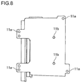
- FIG. 8 is a bottom view of the lens shifting unit of the projector apparatus according to the embodiment.
- FIG. 9 is a plan view showing the placement positions of second through-holes formed in a base plate.
- FIGS. 10(A) to 10(C) show examples of FEM analysis of the amount of displacement of components for a fixing form of a conventional lens shifting unit.
- FIGS. 11(A) to 11(C) show examples of FEM analysis of the amount of displacement of components for the fixing form of the lens shifting unit according to the embodiment.
- FIG. 1 is a perspective view showing how a lens is mounted to a lens shifting unit of a projector apparatus according to an embodiment of the present invention
- FIG. 2 is a perspective view for describing the structure of the lens shifting unit of the projector apparatus according to the embodiment
- FIG. 3 is a plan view of the lens shifting unit of the projector apparatus according to the embodiment as mounted on a projector body
- FIG. 4 is a rear view of the lens shifting unit of the projector apparatus according to the embodiment
- FIG. 5 is a side view of the lens shifting unit of the projector apparatus according to the embodiment
- FIG. 6 is a partially cutaway perspective view of relevant portions of a linear guiding unit
- FIG. 7 is a partially cutaway cross-sectional view of the linear guiding unit of FIG. 6 ;
- FIG. 8 is a bottom view of the lens shifting unit of the projector apparatus according to the embodiment.
- FIG. 9 is a plan view showing the placement positions of second through-holes formed in a base plate; and
- FIGS. 10 and 11 show an example of FEM analysis of the amount of displacement of components associated with the fixing form of the lens shifting unit.
- the up/down direction in FIG. 3 is referred to as X-axis (horizontal) direction; the left/right direction (optical axis direction) in FIG. 3 is as Y-axis (horizontal) direction; and the up/down direction in FIG. 2 is as Z-axis (normal) direction.
- the up/down direction in FIG. 3 is referred to as the left/right direction of the projector apparatus; the left/right direction in FIG. 5 is as the front/back direction of the projector apparatus; and the up/down direction in FIG. 5 is as the up/down direction of the projector apparatus.
- the projector apparatus includes a projector body 2 and a projection lens (hereinafter referred to as “lens 5 ”) which can be attached to and detached from the projector body 2 .
- the lens 5 includes a lens barrel 5 a housing multiple lens groups therein and is replaceable as appropriate.
- the lens 5 also includes a focus ring and a zoom ring, by rotation of which the focus and size of an image or the like projected on a projection surface are adjusted.
- the projector apparatus is utilized as a projector apparatus used for projection mapping, which displays an image onto a building or an object, or in a space, for example, and it employs a large lens having a larger mass than that of a lens used in a general, household-use projector apparatus for projecting an image or the like onto a screen.
- the projector body 2 has a casing 2 a , for example, as shown in FIG. 1 , with a display device, not illustrated, optical units including a light source device, and a lens shifting unit 10 for positional adjustment of the lens being accommodated in the casing 2 a .
- the lens 5 is detachably attached to the lens shifting unit 10 .
- the projector apparatus then magnifies and projects an image or the like on the display device onto a projection surface, such as a building, an object, or a space, via the lens 5 with light emitted from the light source device.
- a projection surface such as a building, an object, or a space
- the lens shifting unit 10 is supported such that the lens 5 is movable relative to the base plate 11 , and includes the base plate 11 which is fixed to a bottom surface 2 b of the casing 2 a , a lens supporting mechanism 20 (a lens supporting unit of the present application) which supports the lens 5 in a movable manner, and a guiding drive mechanism 50 (a guiding mechanism of the present application) which guides the lens supporting mechanism 20 so as to be freely movable in predetermined directions relative to the base plate 11 , as shown in FIGS. 1 and 2 .
- the lens supporting mechanism 20 includes a lens holding plate 21 which fixedly holds the lens 5 , and an intermediate unit 25 provided between the lens holding plate 21 and the base plate 11 .
- the lens holding plate 21 has an insertion hole 21 a of a substantially circular shape in front view, as shown in FIG. 2 .
- the lens 5 is inserted into the insertion hole 21 a and attached via supporting of a part of the lens 5 with a fastener or the like, not illustrated.
- On the outer surface of the insertion hole 21 a an outwardly projecting flange portion 22 is formed.
- the intermediate unit 25 includes a first intermediate member 26 which moves the lens 5 in the Y-axis direction relative to the base plate 11 and a second intermediate member 30 which moves the lens 5 in the X-axis direction relative to the base plate 11 .
- the first intermediate member 26 is a member formed in a substantially flat plate shape along an X-Y plane, for example, has approximately the same size as the base plate 11 , and is positioned overlapping with the base plate 11 .
- the second intermediate member 30 has a frame component 31 reinforced for supporting the lens 5 .
- the frame component 31 is positioned overlapping with the first intermediate member 26 and has a bottom wall portion 31 a formed substantially in the shape of a flat plate having approximately the same size as the first intermediate member 26 and along the X-Y plane, and a front wall portion 31 b and two side wall portions 31 c , 31 d standing on the front and opposite sides of the bottom wall portion 31 a , respectively.
- the front wall portion 31 b has a through-hole 32 for insertion of the lens 5 as shown in FIG. 4 , the through-hole 32 being formed in an ellipsoidal shape with its longer axis in the normal direction.
- the front wall portion 31 b is positioned behind the lens holding plate 21 , and the through-hole 32 formed in the front wall portion 31 b is positioned coaxially with the insertion hole 21 a formed in the lens holding plate 21 so that the front wall portion 31 b can be shifted in the up/down direction without interfering with the lens 5 when the lens 5 is attached.
- the guiding drive mechanism 50 includes first to third guiding drive mechanisms 50 A- 50 C for moving the lens 5 in the normal (Z-axis) and horizontal (X-axis and Y-axis) directions.
- the first guiding drive mechanism 50 A has a linear guiding unit 60 A and a driving unit 70 A. Included as the linear guiding unit 60 A are, as shown in FIG. 6 , a track rail 101 as a track member, a movement block 102 as a movement member incorporated so as to be capable of motion relative to the track rail 101 , and multiple balls 103 as rolling elements which are housed in array within an endless circulating path provided in the movement block 102 and which roll between the track rail 101 and the movement block 102 while receiving a load, for example. In this case, two movement blocks 102 are incorporated for one track rail 101 at the front and the back.
- the track rail 101 is formed such that its cross section perpendicular to the longitudinal direction is of a substantially rectangular shape, and rolling element rolling surfaces 101 - 1 are formed along the longitudinal direction at the opposite sides in the width direction of the track rail 101 .
- rolling element rolling surfaces 101 - 1 are formed along the longitudinal direction at the opposite sides in the width direction of the track rail 101 .
- a total of two strips of rolling element rolling surfaces 101 - 1 are formed, one for each side of the width direction.
- the number and positioning of the rolling element rolling surfaces 101 - 1 may be modified as appropriate.
- insertion holes 101 - 3 for insertion of fasteners are formed as appropriate along the longitudinal direction of the track rails 101 at certain intervals.
- the track rails 101 are fastened to the base plate 11 via the insertion holes 101 - 3 .
- the movement block 102 mentioned above is formed such that its cross section perpendicular to the movement direction is substantially squared U-shaped, and is disposed so as to straddle the track rail 101 .
- a pair of end seals 123 for sealing a clearance between the movement block 102 and the track rail 101 from the outside are mounted on a block body 121 and on a pair of end plates 122 fixed to the end faces of the block body 121 in the movement direction.
- the block body 121 has a horizontal portion 121 - 2 with an attachment surface 121 - 1 , and a pair of sleeve portions 121 - 3 hanging down from the opposite ends of the horizontal portion 121 - 2 .
- a loaded rolling element rolling groove 121 - 5 corresponding to the rolling element rolling surface 101 - 1 of the track rail 101 is provided on the inner surface of each sleeve portion 121 - 3 .
- a rolling element return path 121 - 6 is bored in parallel with the loaded rolling element rolling groove 121 - 5 .
- tap holes 121 - 7 into which bolts (not shown) for fastening the block body 121 are to be screwed are formed.
- the horizontal portion 121 - 2 is fastened to the first intermediate member 26 via the tap holes 121 - 7 .
- a direction changing path 122 - 1 for the balls 103 is formed in the pair of end plates 122 .
- the loaded rolling element rolling groove 121 - 5 of the block body 121 and the rolling element return path 121 - 6 are coupled in communication with each other by the direction changing path 122 - 1 , thus forming an endless circulating path.
- the balls 103 are housed in array within this endless circulating path and circulate in response to relative motion of the track rail 101 and the movement block 102 .
- the balls 103 then roll between the rolling element rolling surface 101 - 1 of the track rail 101 and the loaded rolling element rolling groove 121 - 5 of the movement block 102 while receiving a load.
- the linear guiding unit 60 B of the second guiding drive mechanism 50 B and the linear guiding unit 60 C of the third guiding drive mechanism 50 C shown in FIGS. 4 and 5 have also a similar structure to the linear guiding unit 60 A of the first guiding drive mechanism 50 A, and figures showing their details and descriptions are omitted.
- the track rails 101 are fixed at the right and left of the base plate 11 so as to extend in the front/back direction, the movement blocks 102 are fixed at the front and rear of the first intermediate member 26 respectively, and the first intermediate member 26 is coupled to the base plate 11 in a state that allows the first intermediate member 26 to be guided in the Y-axis direction.
- the track rails 101 are fixed at the front and rear of the first intermediate member 26 so as to extend in the left/right direction
- the movement blocks 102 are fixed on the right and left of the second intermediate member 30 respectively
- the second intermediate member 30 is coupled to the first intermediate member 26 in a state that allows the second intermediate member 30 to be guided in the X-axis direction.
- the track rails 101 are fixed on the right and left of the second intermediate member 30 so as to extend in the up/down direction, the movement blocks 102 are fixed at the right and left of the lens holding plate 21 respectively, and the lens holding plate 21 is coupled to the second intermediate member 30 in a state that allows the lens holding plate 21 to be guided in the Z-axis direction.
- the projector apparatus of this embodiment allows the lens 5 to be freely moved in the X-, Y-, and Z-axis directions relative to the base plate 11 , permitting positional adjustment of the lens 5 .
- the driving unit 70 A has an electric motor M as a driving source, feed screw devices positioned within the housing though not shown, and a transmission mechanism for transmitting the rotation of the electric motor to the feed screw devices.
- the feed screw devices are mounted in a state that allows them to freely rotate about their axes but prevents them from moving in the up-down or left/right direction.
- the driving unit 70 A is attached on the base plate 11 and the terminating end of the feed screw device is fixed to the first intermediate member 26 , so that the first intermediate member 26 is moved in the Y-axis direction by applying driving force in the Y-axis direction to the first intermediate member 26 .
- the driving unit 70 B is attached on the first intermediate member 26 and the terminating end of the feed screw device is fixed to the second intermediate member 30 , so that the second intermediate member is moved in the X-axis direction by applying driving force in the X-axis direction to the second intermediate member.
- the driving unit 70 C is attached to the side wall portion 31 c of the second intermediate member 30 and the terminating end of the feed screw device is fixed to the lens holding plate 21 , so that the lens holding plate 21 is moved in the Z-axis direction by applying driving force in the Z-axis direction to the lens holding plate 21 .
- the lens shifting unit 10 described above is fixed to the bottom surface 2 b of the casing 2 a via the base plate 11 by multiple fixing components 80 (fixing devices of the present application) as shown in FIGS. 1 and 3 .
- the fixing components 80 include multiple first fasteners 81 (the first fixing devices of the present application) provided at the peripheral edge of the base plate 11 and multiple second fasteners 85 (the second fixing devices of the present application) provided on the inner side of the multiple first fasteners 81 .
- the lens shifting unit 10 is fixed to the projector body 2 by the attachment of the fixing components 80 at the peripheral edge and the inner side of the base plate 11 as described above, bending of the base plate 11 that occurs when a large lens is used can be effectively reduced with a simple structure.
- the fixing components 80 may be screws or the like, for example; however, they are not limited to this form and any well-known fixing device capable of fastening between members can be used as appropriate.
- the first fasteners 81 are inserted through first through-holes 11 a , 11 a , 11 a , 11 a formed substantially at the four corners of the base plate 11 to fasten the base plate 11 and the casing 2 a to each other.
- the first through-holes 11 a are formed such that they are visible when seen from above in a situation where the first to third guiding drive mechanisms 50 A- 50 C are at a home position of the lens 5 (hereinafter referred to as “home position”). This allows easy manipulation of a tool during an operation for replacing parts of the lens shifting unit 10 .
- the home position refers to the position at which the lens shifting unit 10 supports the lens 5 in its stationary state (the origin position of the lens).
- the first through-holes 11 a are also formed with an offset in order to provide them outside a range of movement by the first to third guiding drive mechanisms 50 A- 50 C from the home position when seen from above. This allows manipulation of a tool and easy removal of the first fasteners even in a situation where the lens is shifted in the three, or X-, Y-, and Z-axis, directions from the home position. Thus, an operation for replacing parts of the lens shifting unit 10 can be easily performed.
- the second fasteners 85 are inserted through second through-holes 11 b , 11 b formed in the base plate 11 on the inner side of the linear guiding unit 60 A to the right and left of the first guiding drive mechanism 50 A, thereby fastening the base plate 11 and the casing 2 a to each other as shown in FIGS. 3, 8 and 9 .
- FIGS. 10 and 11 show an example of verifying the amount of displacement of components by FEM analysis for different fixing forms of the lens shifting unit 10 when a large lens 5 is attached.
- the difference between the fixing form for a conventional lens shifting unit and that of the present invention is that the fixing form of the conventional lens shifting unit 10 fixes it to the projector body 2 only at four locations in the peripheral edge of the base plate 11 , whereas the fixing form of the lens shifting unit 10 according to this embodiment fixes it to the projector body 2 at four locations in the peripheral edge of the base plate 11 and two locations on the inner side thereof, as shown in FIGS. 10(A) and 11(A) .
- filled areas indicate areas in which no displacement occurs in components
- white areas and hatched areas indicate areas in which displacement occurs in components due to self-weight.
- displacement occurs particularly in the inner side of the base plate 11 with the fixing form of the conventional lens shifting unit 10 , while no displacement occurs in the base plate 11 with the fixing form of the lens shifting unit 10 according to this embodiment.
- the second through-holes 11 b are disposed on the rear inner side of the base plate 11 because it was confirmed that bending occurred on the rear inner side of the base plate 11 as a result of conducting the aforementioned verification for the case of placing the projector apparatus on a floor.
- the second through-holes 11 b will be formed on the front inner side of the base plate 11 and the second fasteners 85 will be attached using the second through-holes 11 b.
- the second through-holes 11 b are formed on the inner side of the linear guiding unit 60 A of the first guiding drive mechanism 50 A and of the linear guiding unit 60 B of the second guiding drive mechanism 50 B in a situation where the first and second guiding drive mechanisms 50 A, 50 B are at the home position.
- each second through-hole 11 b is formed at a position of intersection between a line extended in the X-axis direction from the position at which the movement block 102 of the linear guiding unit 60 A of the first guiding drive mechanism 50 A is fixed and a line extended in the Y-axis direction from the position at which the movement block 102 of the linear guiding unit 60 B of the second guiding drive mechanism 50 B is fixed in a situation where the first and second guiding drive mechanisms 50 A, 50 B are at the home position.
- through-holes 27 , 35 are formed in the first intermediate member 26 and in the bottom wall portion 31 a of the second intermediate member 30 in order to create a space that allows manipulation of a tool for attaching or detaching the second fasteners 85 from above in a situation where the first to third guiding drive mechanisms are at the home position. This allows easy manipulation of a tool during an operation for replacing parts of the lens shifting unit 10 and facilitates the operation for replacing parts of the lens shifting unit 10 .
- the through-hole 35 has a size including the range of movement by the first to third guiding drive mechanisms 50 A- 50 C from the home position when seen from above. This enables manipulation of a tool via the through-hole 35 and allows for easy removal of the second fasteners 85 even in a situation where the lens shifting unit is shifted in the three, or X-, Y-, and Z-axis directions from the home position. Thus, an operation for replacing parts of the lens shifting unit 10 can be easily performed.
- the present invention is not limited to the above embodiment but may be modified in various manners within a range not altering the gist of the present invention.
- a space for manipulating a tool may be formed by cutting this portion from the back side. This would provide a space for allowing manipulation of a tool above the second fasteners 85 , thus permitting easy attachment and detachment of the second fasteners 85 and facilitating an operation for replacing parts of the lens shifting unit 10 .
- first fasteners 81 and the second fasteners 85 are both not limited but may be modified as appropriate.
- the structure of the guiding drive mechanism 50 shown in the above example is only illustrative and other well-known guiding drive mechanisms may be employed as appropriate.
Abstract
Description
- [Patent Literature 1] Japanese Patent No. 4545471
- 2 projector body
- 5 lens
- 10 lens shifting unit
- 11 base plate
- 50 guiding drive mechanism
- 80 fixing component
- 81 first fastener
- 85 second fastener
- 35 through-hole
Claims (4)
Applications Claiming Priority (3)
| Application Number | Priority Date | Filing Date | Title |
|---|---|---|---|
| JP2017006025 | 2017-01-17 | ||
| JP2017-006025 | 2017-01-17 | ||
| PCT/JP2017/039769 WO2018135090A1 (en) | 2017-01-17 | 2017-11-02 | Projector device |
Publications (2)
| Publication Number | Publication Date |
|---|---|
| US20190353991A1 US20190353991A1 (en) | 2019-11-21 |
| US10859895B2 true US10859895B2 (en) | 2020-12-08 |
Family
ID=62908324
Family Applications (1)
| Application Number | Title | Priority Date | Filing Date |
|---|---|---|---|
| US16/474,223 Active US10859895B2 (en) | 2017-01-17 | 2017-11-02 | Projector apparatus |
Country Status (6)
| Country | Link |
|---|---|
| US (1) | US10859895B2 (en) |
| JP (1) | JP7038066B2 (en) |
| CN (1) | CN110199225B (en) |
| DE (1) | DE112017006849T5 (en) |
| TW (1) | TWI762529B (en) |
| WO (1) | WO2018135090A1 (en) |
Families Citing this family (2)
| Publication number | Priority date | Publication date | Assignee | Title |
|---|---|---|---|---|
| KR20210079788A (en) * | 2019-12-20 | 2021-06-30 | 엘지전자 주식회사 | Projector |
| CA206058S (en) * | 2021-05-11 | 2023-07-05 | Roxx GmbH | Accessory holder for a lamp |
Citations (14)
| Publication number | Priority date | Publication date | Assignee | Title |
|---|---|---|---|---|
| JPH09222665A (en) | 1996-02-19 | 1997-08-26 | West Electric Co Ltd | Picture projector |
| JP2002124801A (en) | 2000-10-13 | 2002-04-26 | New Japan Radio Co Ltd | Satellite broadcast frequency converter with built-in transmission frequency band blocking filter |
| JP2004004206A (en) | 2002-05-31 | 2004-01-08 | Matsushita Electric Ind Co Ltd | Projection-type display device |
| US20050117127A1 (en) * | 2003-11-27 | 2005-06-02 | Samsung Electronics Co., Ltd. | Device for controlling projection lens shift in a projector |
| JP4545471B2 (en) | 2004-03-30 | 2010-09-15 | Thk株式会社 | Lens movement mechanism |
| JP2011158657A (en) | 2010-01-29 | 2011-08-18 | Sony Corp | Image projection unit and projection type image display device |
| US20110235002A1 (en) * | 2010-03-24 | 2011-09-29 | Hon Hai Precision Industry Co., Ltd. | Projector |
| US20110310364A1 (en) | 2010-06-22 | 2011-12-22 | Seiko Epson Corporation | Projector |
| US20120218527A1 (en) * | 2011-02-24 | 2012-08-30 | Canon Kabushiki Kaisha | Image projection apparatus |
| US20120249979A1 (en) * | 2011-04-01 | 2012-10-04 | Seiko Epson Corporation | Projector, projection unit, and interactive board |
| US20120327377A1 (en) | 2011-06-24 | 2012-12-27 | Casio Computer Co., Ltd. | Light source device and projector |
| WO2013054427A1 (en) | 2011-10-13 | 2013-04-18 | 日立コンシューマエレクトロニクス株式会社 | Projection video display device |
| US20130265551A1 (en) * | 2012-04-10 | 2013-10-10 | Seiko Epson Corporation | Projection system, support, and image display method |
| US20140036237A1 (en) * | 2012-08-06 | 2014-02-06 | Seiko Epson Corporation | Optical device, projector, and method of manufacturing optical device |
Family Cites Families (9)
| Publication number | Priority date | Publication date | Assignee | Title |
|---|---|---|---|---|
| US20020044264A1 (en) | 2000-10-17 | 2002-04-18 | Chang-Hsing Lu | Optical lens module adjustable in two dimensions |
| JP2007272071A (en) * | 2006-03-31 | 2007-10-18 | Sony Corp | Rear projection display device |
| JP2007286121A (en) * | 2006-04-12 | 2007-11-01 | Seiko Epson Corp | Manufacturing apparatus for optical device, manufacturing method therefor and projector |
| CN101464621B (en) * | 2008-12-17 | 2010-12-08 | 顾金昌 | Stereo digital jigsaw imaging lens moving apparatus and method thereof |
| JP2010160232A (en) * | 2009-01-07 | 2010-07-22 | Sanyo Electric Co Ltd | Projection type video display device |
| CN201732199U (en) * | 2010-02-09 | 2011-02-02 | 彩亿科技(深圳)有限公司 | Focusing device of miniature projector |
| JP5074603B2 (en) * | 2011-01-11 | 2012-11-14 | 三洋電機株式会社 | Lens moving mechanism and liquid crystal projector |
| CN106324960B (en) * | 2015-07-07 | 2018-10-30 | 中强光电股份有限公司 | Projection arrangement and camera lens module |
| CN205750250U (en) * | 2016-07-01 | 2016-11-30 | 和信精密科技(吴江)有限公司 | A kind of New Projection Display |
-
2017
- 2017-11-02 CN CN201780083676.3A patent/CN110199225B/en active Active
- 2017-11-02 DE DE112017006849.5T patent/DE112017006849T5/en active Pending
- 2017-11-02 JP JP2018562889A patent/JP7038066B2/en active Active
- 2017-11-02 US US16/474,223 patent/US10859895B2/en active Active
- 2017-11-02 WO PCT/JP2017/039769 patent/WO2018135090A1/en active Application Filing
- 2017-11-22 TW TW106140501A patent/TWI762529B/en active
Patent Citations (17)
| Publication number | Priority date | Publication date | Assignee | Title |
|---|---|---|---|---|
| JPH09222665A (en) | 1996-02-19 | 1997-08-26 | West Electric Co Ltd | Picture projector |
| JP2002124801A (en) | 2000-10-13 | 2002-04-26 | New Japan Radio Co Ltd | Satellite broadcast frequency converter with built-in transmission frequency band blocking filter |
| JP2004004206A (en) | 2002-05-31 | 2004-01-08 | Matsushita Electric Ind Co Ltd | Projection-type display device |
| US20050117127A1 (en) * | 2003-11-27 | 2005-06-02 | Samsung Electronics Co., Ltd. | Device for controlling projection lens shift in a projector |
| JP4545471B2 (en) | 2004-03-30 | 2010-09-15 | Thk株式会社 | Lens movement mechanism |
| JP2011158657A (en) | 2010-01-29 | 2011-08-18 | Sony Corp | Image projection unit and projection type image display device |
| US20110235002A1 (en) * | 2010-03-24 | 2011-09-29 | Hon Hai Precision Industry Co., Ltd. | Projector |
| JP2012008185A (en) | 2010-06-22 | 2012-01-12 | Seiko Epson Corp | Projector |
| US20110310364A1 (en) | 2010-06-22 | 2011-12-22 | Seiko Epson Corporation | Projector |
| US20120218527A1 (en) * | 2011-02-24 | 2012-08-30 | Canon Kabushiki Kaisha | Image projection apparatus |
| US20120249979A1 (en) * | 2011-04-01 | 2012-10-04 | Seiko Epson Corporation | Projector, projection unit, and interactive board |
| US20120327377A1 (en) | 2011-06-24 | 2012-12-27 | Casio Computer Co., Ltd. | Light source device and projector |
| JP2013008555A (en) | 2011-06-24 | 2013-01-10 | Casio Computer Co Ltd | Light source device and projector |
| WO2013054427A1 (en) | 2011-10-13 | 2013-04-18 | 日立コンシューマエレクトロニクス株式会社 | Projection video display device |
| US20140300829A1 (en) | 2011-10-13 | 2014-10-09 | Kazumasa Ueoka | Projection video display device |
| US20130265551A1 (en) * | 2012-04-10 | 2013-10-10 | Seiko Epson Corporation | Projection system, support, and image display method |
| US20140036237A1 (en) * | 2012-08-06 | 2014-02-06 | Seiko Epson Corporation | Optical device, projector, and method of manufacturing optical device |
Non-Patent Citations (1)
| Title |
|---|
| International Search Report dated Feb. 6, 2018, issued in counterpart application No. PCT/JP2017/039769 (2 pages). |
Also Published As
| Publication number | Publication date |
|---|---|
| JP7038066B2 (en) | 2022-03-17 |
| WO2018135090A1 (en) | 2018-07-26 |
| TWI762529B (en) | 2022-05-01 |
| CN110199225A (en) | 2019-09-03 |
| CN110199225B (en) | 2021-10-22 |
| TW201841013A (en) | 2018-11-16 |
| JPWO2018135090A1 (en) | 2019-11-07 |
| DE112017006849T5 (en) | 2019-09-26 |
| US20190353991A1 (en) | 2019-11-21 |
Similar Documents
| Publication | Publication Date | Title |
|---|---|---|
| US20200205305A1 (en) | Display installation apparatus and multi-display having the same | |
| US10859895B2 (en) | Projector apparatus | |
| KR20190074014A (en) | Surveillance camera assembly and method for installing the same | |
| JP2015200710A (en) | Display device mounting metal fitting and display device mounting fixture | |
| JP2018174345A (en) | Rack system | |
| KR20070072391A (en) | Rear projection display apparatus | |
| KR20180066493A (en) | Display Appratus | |
| KR20180032117A (en) | Display Appratus | |
| JP4545471B2 (en) | Lens movement mechanism | |
| KR20180046711A (en) | Display Appratus | |
| JP2008262045A (en) | Projection type image display apparatus | |
| JP4762003B2 (en) | Display device | |
| JP4749731B2 (en) | Rack mount | |
| KR101066139B1 (en) | Connecting device for screen display apparatus | |
| US10718927B2 (en) | Lens moving mechanism | |
| KR20180036045A (en) | multi-vision devices installed | |
| JP6120532B2 (en) | Multivision display device | |
| JP3888039B2 (en) | projector | |
| KR20070072405A (en) | Rear projection display apparatus | |
| US20190250365A1 (en) | Lens moving mechanism | |
| JP2011123509A (en) | Lens moving mechanism and liquid crystal projector | |
| CN214036416U (en) | Positioning and attaching device | |
| US10712528B2 (en) | Lens moving mechanism | |
| JP2018092203A (en) | Display unit fixture | |
| JP2010039130A (en) | Projection type video display apparatus |
Legal Events
| Date | Code | Title | Description |
|---|---|---|---|
| AS | Assignment |
Owner name: NEC DISPLAY SOLUTIONS, LTD., JAPAN Free format text: ASSIGNMENT OF ASSIGNORS INTEREST;ASSIGNORS:SHIMAMURA, MARIE;HIROTA, JUN;FUKUSHIMA, HAJIME;AND OTHERS;REEL/FRAME:049612/0077 Effective date: 20190621 Owner name: THK CO., LTD., JAPAN Free format text: ASSIGNMENT OF ASSIGNORS INTEREST;ASSIGNORS:SHIMAMURA, MARIE;HIROTA, JUN;FUKUSHIMA, HAJIME;AND OTHERS;REEL/FRAME:049612/0077 Effective date: 20190621 |
|
| FEPP | Fee payment procedure |
Free format text: ENTITY STATUS SET TO UNDISCOUNTED (ORIGINAL EVENT CODE: BIG.); ENTITY STATUS OF PATENT OWNER: LARGE ENTITY |
|
| STPP | Information on status: patent application and granting procedure in general |
Free format text: DOCKETED NEW CASE - READY FOR EXAMINATION |
|
| STPP | Information on status: patent application and granting procedure in general |
Free format text: NON FINAL ACTION MAILED |
|
| STPP | Information on status: patent application and granting procedure in general |
Free format text: RESPONSE TO NON-FINAL OFFICE ACTION ENTERED AND FORWARDED TO EXAMINER |
|
| AS | Assignment |
Owner name: THK CO., LTD., JAPAN Free format text: ASSIGNMENT OF ASSIGNORS INTEREST;ASSIGNOR:NEC DISPLAY SOLUTIONS, LTD.;REEL/FRAME:053999/0225 Effective date: 20200928 |
|
| STCF | Information on status: patent grant |
Free format text: PATENTED CASE |
|
| CC | Certificate of correction |