US10859820B2 - Head-up display device - Google Patents
Head-up display device Download PDFInfo
- Publication number
- US10859820B2 US10859820B2 US16/080,685 US201716080685A US10859820B2 US 10859820 B2 US10859820 B2 US 10859820B2 US 201716080685 A US201716080685 A US 201716080685A US 10859820 B2 US10859820 B2 US 10859820B2
- Authority
- US
- United States
- Prior art keywords
- display
- image
- control unit
- pixels
- luminance
- Prior art date
- Legal status (The legal status is an assumption and is not a legal conclusion. Google has not performed a legal analysis and makes no representation as to the accuracy of the status listed.)
- Expired - Fee Related, expires
Links
Images


Classifications
-
- G—PHYSICS
- G02—OPTICS
- G02B—OPTICAL ELEMENTS, SYSTEMS OR APPARATUS
- G02B27/00—Optical systems or apparatus not provided for by any of the groups G02B1/00 - G02B26/00, G02B30/00
- G02B27/01—Head-up displays
- G02B27/0101—Head-up displays characterised by optical features
-
- B—PERFORMING OPERATIONS; TRANSPORTING
- B60—VEHICLES IN GENERAL
- B60K—ARRANGEMENT OR MOUNTING OF PROPULSION UNITS OR OF TRANSMISSIONS IN VEHICLES; ARRANGEMENT OR MOUNTING OF PLURAL DIVERSE PRIME-MOVERS IN VEHICLES; AUXILIARY DRIVES FOR VEHICLES; INSTRUMENTATION OR DASHBOARDS FOR VEHICLES; ARRANGEMENTS IN CONNECTION WITH COOLING, AIR INTAKE, GAS EXHAUST OR FUEL SUPPLY OF PROPULSION UNITS IN VEHICLES
- B60K35/00—Instruments specially adapted for vehicles; Arrangement of instruments in or on vehicles
- B60K35/20—Output arrangements, i.e. from vehicle to user, associated with vehicle functions or specially adapted therefor
- B60K35/21—Output arrangements, i.e. from vehicle to user, associated with vehicle functions or specially adapted therefor using visual output, e.g. blinking lights or matrix displays
- B60K35/213—Virtual instruments
-
- B—PERFORMING OPERATIONS; TRANSPORTING
- B60—VEHICLES IN GENERAL
- B60K—ARRANGEMENT OR MOUNTING OF PROPULSION UNITS OR OF TRANSMISSIONS IN VEHICLES; ARRANGEMENT OR MOUNTING OF PLURAL DIVERSE PRIME-MOVERS IN VEHICLES; AUXILIARY DRIVES FOR VEHICLES; INSTRUMENTATION OR DASHBOARDS FOR VEHICLES; ARRANGEMENTS IN CONNECTION WITH COOLING, AIR INTAKE, GAS EXHAUST OR FUEL SUPPLY OF PROPULSION UNITS IN VEHICLES
- B60K35/00—Instruments specially adapted for vehicles; Arrangement of instruments in or on vehicles
- B60K35/20—Output arrangements, i.e. from vehicle to user, associated with vehicle functions or specially adapted therefor
- B60K35/21—Output arrangements, i.e. from vehicle to user, associated with vehicle functions or specially adapted therefor using visual output, e.g. blinking lights or matrix displays
- B60K35/215—Output arrangements, i.e. from vehicle to user, associated with vehicle functions or specially adapted therefor using visual output, e.g. blinking lights or matrix displays characterised by the combination of multiple visual outputs, e.g. combined instruments with analogue meters and additional displays
-
- B—PERFORMING OPERATIONS; TRANSPORTING
- B60—VEHICLES IN GENERAL
- B60K—ARRANGEMENT OR MOUNTING OF PROPULSION UNITS OR OF TRANSMISSIONS IN VEHICLES; ARRANGEMENT OR MOUNTING OF PLURAL DIVERSE PRIME-MOVERS IN VEHICLES; AUXILIARY DRIVES FOR VEHICLES; INSTRUMENTATION OR DASHBOARDS FOR VEHICLES; ARRANGEMENTS IN CONNECTION WITH COOLING, AIR INTAKE, GAS EXHAUST OR FUEL SUPPLY OF PROPULSION UNITS IN VEHICLES
- B60K35/00—Instruments specially adapted for vehicles; Arrangement of instruments in or on vehicles
- B60K35/20—Output arrangements, i.e. from vehicle to user, associated with vehicle functions or specially adapted therefor
- B60K35/21—Output arrangements, i.e. from vehicle to user, associated with vehicle functions or specially adapted therefor using visual output, e.g. blinking lights or matrix displays
- B60K35/23—Head-up displays [HUD]
-
- B—PERFORMING OPERATIONS; TRANSPORTING
- B60—VEHICLES IN GENERAL
- B60K—ARRANGEMENT OR MOUNTING OF PROPULSION UNITS OR OF TRANSMISSIONS IN VEHICLES; ARRANGEMENT OR MOUNTING OF PLURAL DIVERSE PRIME-MOVERS IN VEHICLES; AUXILIARY DRIVES FOR VEHICLES; INSTRUMENTATION OR DASHBOARDS FOR VEHICLES; ARRANGEMENTS IN CONNECTION WITH COOLING, AIR INTAKE, GAS EXHAUST OR FUEL SUPPLY OF PROPULSION UNITS IN VEHICLES
- B60K35/00—Instruments specially adapted for vehicles; Arrangement of instruments in or on vehicles
- B60K35/20—Output arrangements, i.e. from vehicle to user, associated with vehicle functions or specially adapted therefor
- B60K35/28—Output arrangements, i.e. from vehicle to user, associated with vehicle functions or specially adapted therefor characterised by the type of the output information, e.g. video entertainment or vehicle dynamics information; characterised by the purpose of the output information, e.g. for attracting the attention of the driver
-
- B—PERFORMING OPERATIONS; TRANSPORTING
- B60—VEHICLES IN GENERAL
- B60K—ARRANGEMENT OR MOUNTING OF PROPULSION UNITS OR OF TRANSMISSIONS IN VEHICLES; ARRANGEMENT OR MOUNTING OF PLURAL DIVERSE PRIME-MOVERS IN VEHICLES; AUXILIARY DRIVES FOR VEHICLES; INSTRUMENTATION OR DASHBOARDS FOR VEHICLES; ARRANGEMENTS IN CONNECTION WITH COOLING, AIR INTAKE, GAS EXHAUST OR FUEL SUPPLY OF PROPULSION UNITS IN VEHICLES
- B60K35/00—Instruments specially adapted for vehicles; Arrangement of instruments in or on vehicles
- B60K35/60—Instruments characterised by their location or relative disposition in or on vehicles
-
- B—PERFORMING OPERATIONS; TRANSPORTING
- B60—VEHICLES IN GENERAL
- B60K—ARRANGEMENT OR MOUNTING OF PROPULSION UNITS OR OF TRANSMISSIONS IN VEHICLES; ARRANGEMENT OR MOUNTING OF PLURAL DIVERSE PRIME-MOVERS IN VEHICLES; AUXILIARY DRIVES FOR VEHICLES; INSTRUMENTATION OR DASHBOARDS FOR VEHICLES; ARRANGEMENTS IN CONNECTION WITH COOLING, AIR INTAKE, GAS EXHAUST OR FUEL SUPPLY OF PROPULSION UNITS IN VEHICLES
- B60K35/00—Instruments specially adapted for vehicles; Arrangement of instruments in or on vehicles
- B60K35/80—Arrangements for controlling instruments
- B60K35/81—Arrangements for controlling instruments for controlling displays
-
- G—PHYSICS
- G02—OPTICS
- G02B—OPTICAL ELEMENTS, SYSTEMS OR APPARATUS
- G02B27/00—Optical systems or apparatus not provided for by any of the groups G02B1/00 - G02B26/00, G02B30/00
- G02B27/01—Head-up displays
-
- G—PHYSICS
- G09—EDUCATION; CRYPTOGRAPHY; DISPLAY; ADVERTISING; SEALS
- G09G—ARRANGEMENTS OR CIRCUITS FOR CONTROL OF INDICATING DEVICES USING STATIC MEANS TO PRESENT VARIABLE INFORMATION
- G09G5/00—Control arrangements or circuits for visual indicators common to cathode-ray tube indicators and other visual indicators
- G09G5/10—Intensity circuits
-
- G—PHYSICS
- G09—EDUCATION; CRYPTOGRAPHY; DISPLAY; ADVERTISING; SEALS
- G09G—ARRANGEMENTS OR CIRCUITS FOR CONTROL OF INDICATING DEVICES USING STATIC MEANS TO PRESENT VARIABLE INFORMATION
- G09G5/00—Control arrangements or circuits for visual indicators common to cathode-ray tube indicators and other visual indicators
- G09G5/36—Control arrangements or circuits for visual indicators common to cathode-ray tube indicators and other visual indicators characterised by the display of a graphic pattern, e.g. using an all-points-addressable [APA] memory
-
- H—ELECTRICITY
- H04—ELECTRIC COMMUNICATION TECHNIQUE
- H04N—PICTORIAL COMMUNICATION, e.g. TELEVISION
- H04N5/00—Details of television systems
- H04N5/74—Projection arrangements for image reproduction, e.g. using eidophor
-
- B—PERFORMING OPERATIONS; TRANSPORTING
- B60—VEHICLES IN GENERAL
- B60K—ARRANGEMENT OR MOUNTING OF PROPULSION UNITS OR OF TRANSMISSIONS IN VEHICLES; ARRANGEMENT OR MOUNTING OF PLURAL DIVERSE PRIME-MOVERS IN VEHICLES; AUXILIARY DRIVES FOR VEHICLES; INSTRUMENTATION OR DASHBOARDS FOR VEHICLES; ARRANGEMENTS IN CONNECTION WITH COOLING, AIR INTAKE, GAS EXHAUST OR FUEL SUPPLY OF PROPULSION UNITS IN VEHICLES
- B60K2360/00—Indexing scheme associated with groups B60K35/00 or B60K37/00 relating to details of instruments or dashboards
- B60K2360/20—Optical features of instruments
- B60K2360/33—Illumination features
- B60K2360/334—Projection means
-
- B60K2370/334—
-
- G—PHYSICS
- G02—OPTICS
- G02B—OPTICAL ELEMENTS, SYSTEMS OR APPARATUS
- G02B27/00—Optical systems or apparatus not provided for by any of the groups G02B1/00 - G02B26/00, G02B30/00
- G02B27/01—Head-up displays
- G02B27/0101—Head-up displays characterised by optical features
- G02B2027/0118—Head-up displays characterised by optical features comprising devices for improving the contrast of the display / brillance control visibility
-
- G—PHYSICS
- G02—OPTICS
- G02B—OPTICAL ELEMENTS, SYSTEMS OR APPARATUS
- G02B27/00—Optical systems or apparatus not provided for by any of the groups G02B1/00 - G02B26/00, G02B30/00
- G02B27/01—Head-up displays
- G02B27/0101—Head-up displays characterised by optical features
- G02B2027/014—Head-up displays characterised by optical features comprising information/image processing systems
-
- G—PHYSICS
- G09—EDUCATION; CRYPTOGRAPHY; DISPLAY; ADVERTISING; SEALS
- G09G—ARRANGEMENTS OR CIRCUITS FOR CONTROL OF INDICATING DEVICES USING STATIC MEANS TO PRESENT VARIABLE INFORMATION
- G09G2320/00—Control of display operating conditions
- G09G2320/06—Adjustment of display parameters
- G09G2320/0686—Adjustment of display parameters with two or more screen areas displaying information with different brightness or colours
-
- G—PHYSICS
- G09—EDUCATION; CRYPTOGRAPHY; DISPLAY; ADVERTISING; SEALS
- G09G—ARRANGEMENTS OR CIRCUITS FOR CONTROL OF INDICATING DEVICES USING STATIC MEANS TO PRESENT VARIABLE INFORMATION
- G09G2380/00—Specific applications
- G09G2380/10—Automotive applications
Definitions
- the present disclosure relates to a head-up display device.
- a head-up display device which projects a display image in a vehicle onto a projection member, which transmits an external real image, to display the display image superimposed on the external real image for virtual image display visible to an occupant in the vehicle.
- Patent Literature 1 As a type of the HUD device described above, disclosed in Patent Literature 1, a projection of a display image in a device that is superimposed on an external real image for virtual image display in order to notify an occupant in a vehicle of information is controlled by a navigation apparatus to adjust a virtual display state of the display image.
- the device disclosed in Patent Literature 1 contemplates a control that enables a visibility of the external real image to be enhanced by increasing an overall transparency of the display image.
- a head-up display device is configured to project a display image onto a projection member, which is configured to transmit an external real image, to display the display image superimposed on the external real image to indicate a virtual image visible to an occupant in the vehicle.
- the head-up display device comprises a projection unit configured to project a notification image as the display image onto the projection member to notify the occupant of specific information.
- the head-up display device further comprises a display control unit configured to control the projection unit to adjust a virtual image display state of the display image to cut specific pixels, which form an inner portion inside an outer edge portion of the notification image, in a virtual image display.
- FIG. 1 is a configuration diagram showing an HUD device according to a first embodiment
- FIG. 2 is a front view showing a virtual image display state by the HUD device according to the first embodiment
- FIG. 3 is a front view showing a notification image displayed as a virtual image by the HUD device according to the first embodiment
- FIG. 4 is a front view showing a superimposed state of the notification image displayed as the virtual image by the HUD device on an external real image according to the first embodiment
- FIG. 5 is a front view showing a notification image displayed as a virtual image by an HUD device according to a second embodiment
- FIG. 6 (a) to (e) are front views showing a superimposed state of a notification image displayed as a virtual image by the HUD device on an external real image every time according to a third embodiment
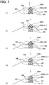
- FIG. 7 (a) to (e) are front views showing a superimposed state of a notification image displayed as a virtual image by the HUD device on an external real image every time according to a fourth embodiment
- FIG. 8 (a) to (e) are front views showing a superimposed state of a notification image displayed as a virtual image by the HUD device on an external real image every time according to a fifth embodiment
- FIG. 9 is a front view illustrating a modification of FIG. 3 .
- FIG. 10 is a front view illustrating a modification of FIG. 5 .
- FIG. 11 (a) to (e) are front views illustrating a modification of FIG. 6 .
- an HUD device 1 is mounted on a vehicle 2 .
- the HUD device 1 includes a projection unit 10 and a display control unit 20 .
- a vertical direction and a lateral direction in FIGS. 1 and 2 substantially coincide with the vertical direction and the horizontal direction of the vehicle 2 on a horizontal plane.
- the projection unit 10 is accommodated in an instrument panel 3 in the interior of the vehicle 2 .
- the projection unit 10 has a projector 11 and an optical system 12 .
- the projector 11 is, for example, a liquid crystal type or scanning type projector. In the present embodiment, the projector 11 forms and displays a color display image 9 .
- the optical system 12 includes at least one optical member such as a reflecting mirror. The optical system 12 guides a light flux of the display image 9 projected from the projector 11 to outside the instrument panel 3 by reflection or the like, for example.
- the light flux is guided by the optical system 12 as indicated by one-dot chain lines in FIG. 1 so that the display image 9 is projected onto a front windshield 4 of the vehicle 2 .
- the front windshield 4 which is made of a light transmissive glass as a “projection member,” reflects the light flux of the projected display image 9 and transmits a light flux of an external real image 5 existing outside and in front of the vehicle 2 .
- the light flux of the display image 9 reflected by the front windshield 4 and the light flux of the external real image 5 transmitted through the front windshield 4 are incident on pupils of an occupant 7 who is seated on a driver's seat 6 in the vehicle 2 .
- a virtual image of the display image 9 to be imaged ahead of the front windshield 4 out of the vehicle 2 is visually recognized on a driver's seat 6 side with respect to the external real image 5 by the occupant 7 .
- the display image 9 on which the external real image 5 is superimposed on the driver's seat 6 side is displayed as the virtual image visible to the occupant 7 .
- the display image 9 thus displayed as the virtual image fulfills a notifying function to notify the occupant 7 of predetermined information in the vehicle 2 .
- notification information by the display image 9 for example, instrument information such as a vehicle speed, traffic sign information such as a speed limit sign, warning information such as over speed warning, communication information on telephones or mails, path information such as turn by turn, and the like are cited.
- the path information is employed as “specific information” which has little influence on compliance with traffic regulations.
- the display image 9 for notifying the path information is set as the notification image 90 .
- the display control unit 20 is accommodated in the instrument panel 3 in the vehicle 2 together with the projection unit 10 .
- the display control unit 20 is mainly configured by a microcomputer and an image processing circuit.
- the display control unit 20 is electrically connected to at least the projector 11 of the projection unit 10 .
- the display control unit 20 is connected to electrical components required for a virtual image display, for example, another display control unit, a sensor, and so on of the vehicle 2 in a communicatable manner.
- the display control unit 20 controls the projection unit 10 based on signals from the connected electrical components. As a result, the display control unit 20 adjusts a virtual image display state of the display image 9 including a notification image 90 .
- the display control unit 20 forms the notification image 90 from normal pixels 90 a and specific pixels 90 b as shown in FIG. 3 .
- the normal pixels 90 a are set to a predetermined number of pixels forming an outline of an outer shape as an outer edge portion 900 on an outside of a one-dot chain line in a cross-hatched portion of the notification image 90 in FIG. 3 .
- the normal pixels 90 a are also set to a predetermined number of pixels forming a remaining part 902 , except for the specific pixels 90 b , as an inner portion 901 inside the one-dotted chain line in the cross-hatched portion of the notification image 90 in FIG. 3 , that is, inside the outer edge portion 900 .
- a contrast ratio of enhancing the visibility of the external real image 5 superimposed as shown in FIG. 4 is imparted to the normal pixels 90 a forming the outer edge portion 900 and the remaining part 902 of the inner portion 901 except for the specific pixels 90 b in the notification image 90 as described above. Therefore, the display control unit 20 forms the normal pixels 90 a with a color tone of relatively high luminance such as white where each gradation value of RGB is the maximum value, for example.
- the specific pixels 90 b are set to a predetermined number of pixels at each of multiple places where the normal pixels 90 a are not set in the inner portion 901 of the notification image 90 , as indicated by outlined squares in FIG. 3 .
- the virtual image display is cut in the specific pixels 90 b at the multiple places in the inner portion 901 of the notification image 90 so that the external real image 5 superimposed as shown in FIG. 4 is substantially transmitted as it is as shown in FIG. 4 .
- the notification image 90 realizes visibility as if it is translucent in a pseudo manner. Therefore, the display control unit 20 forms the specific pixels 90 b at all of the places, for example, with zero luminance where each gradation value of RGB becomes the minimum value.
- the display control unit 20 adjusts an outer shape of the specific pixels 90 b at each place, which is determined according to a placement mode of the component pixels to substantially the same shape.
- the display control unit 20 adjusts a lateral outer size Xp and a lateral placement interval Xi of the specific pixels 90 b at each place, which are determined according to the number of placement of the component pixels, to respective substantially constant dimensions.
- the display control unit 20 adjusts an outer size Yp in a vertical direction and a placement interval Yi in the vertical direction of the specific pixels 90 b at each place, which are determined according to the number of placement of the component pixels, to respective substantially constant dimensions.
- the specific pixels 90 b at each place are formed with a square shape whose outer sizes Xp and Yp are substantially the same dimensions so that a total area of the specific pixels 90 b at each place occupies, for example, a proportion of about 20 to 70% in an entire area of the notification image 90 .
- the virtual image display of the specific pixels 90 b forming the inner portion 901 inside the outer edge portion 900 is cut.
- the external real image 5 is substantially transmitted as it is at the specific pixels 90 b where the virtual image display is cut in the inner portion 901 , while a high-visibility contrast ratio to the external real image 5 can be imparted to the outer edge portion 900 and the inner portion 901 except for the specific pixels 90 b .
- the specific pixels 90 b in which the virtual image display is cut appears at the multiple places in the inner portion 901 of the notification image 90 , as a result of which the number of places where the external real image 5 is substantially transmitted as it is increases. Therefore, while ensuring the visibility of the external real image 5 , the high-visibility contrast ratio to the external real image 5 is imparted to the outer edge portion 900 of the notification image 90 and the inner portion 901 except for the specific pixels 90 b to enable the notification property of information to be ensured.
- the multiple places where the specific pixels 90 b where the virtual image display is cut appear are arranged in a checkered pattern at the inner portion 901 of the notification image 90 .
- image processing for forming the notification image 90 can be simplified, and a responsiveness of displaying the virtual image of the notification image 90 can be enhanced.
- a second embodiment of the present disclosure is a modification of the first embodiment.
- multiple places at which specific pixels 2090 b indicated by outlined squares in FIG. 5 appear on an inner portion 901 of a notification image 2090 are arranged at random.
- an outer shape of the specific pixels 2090 b at each place which is determined according to a placement mode of the component pixels, is adjusted to a similar shape by the display control unit 20 .
- a lateral outer size Xp and a lateral placement interval Xi of the specific pixels 2090 b at each place which are determined according to the number of placement of the component pixels, are adjusted to respective different dimensions by the display control unit 20 .
- an outer size Yp in a vertical direction and a placement interval Yi in the vertical direction of the specific pixels 2090 b at each place are adjusted to respective different dimensions by the display control unit 20 .
- the details of the specific pixels 2090 b other than those described above are substantially the same as those of the specific pixels 90 b described in the first embodiment.
- the multiple places at which the specific pixels 2090 b where the virtual image display is cut appear are arranged at random in the inner portion 901 of the notification image 2090 .
- the random arrangement described above the deterioration in visibility such as moiré caused by regular arrangement of the specific pixels 2090 b can be reduced.
- the effect of reducing the deterioration of visibility such as moiré increases.
- a third embodiment of the present disclosure is a modification of the first embodiment.
- multiple places at which specific pixels 3090 b indicated by outlined squares in (a) to (e) in FIG. 6 appear on an inner portion 901 of a notification image 3090 are displaced with time.
- the specific pixels 3090 b at each place is displaced from a lower side toward an upper side in the inner portion 901 in a virtual image display state, to thereby realize a frame animation moving in a traveling direction of the vehicle 2 .
- the specific pixels 3090 b in each place are formed by the display control unit 20 in a moving image form in which the component pixels decrease from the lower side and increase upward for each frame.
- the specific pixels 3090 b are formed in a moving image state in which the component pixels increase upward from the boundary for each frame.
- the specific pixels 3090 b are formed in a moving image state in which the component pixels decrease downward from the boundary for each frame.
- the details of the specific pixels 3090 b other than those described above are substantially the same as those of the specific pixels 90 b described in the first embodiment.
- the places at which the specific pixels 3090 b where the virtual image display is cut appear are displaced in the inner portion 901 of the notification image 3090 with time. According to the above configuration, since the places at which the specific pixels 3090 b appear are displaced with time as places at which the external real image 5 is transmitted as it is, discrimination of the external real image 5 shown in (a) to (e) in FIG. 6 can be enhanced while the notification property of the information by the notification image 3090 is ensured.
- a fourth embodiment of the present disclosure is a modification of the first embodiment. Increasing and decreasing luminance of normal pixels 4090 a are repeated for a notification image 4090 with a change in line spacing cross-hatched in (a) to (e) in FIG. 7 every time according to the fourth embodiment.
- a frame animation is realized in which the luminance of the virtual image display of the normal pixels 4090 a is alternately switched between a normal luminance Lh on a higher luminance side and a changed luminance Ll on a lower luminance side.
- a ratio between the number of frames at the time of the higher luminance and the number of frames at the time of the lower luminance is set to, for example, 1:1, 2:1, 3:1 or the like so as to prevent the occupant 7 from feeling flickering at the time of visual recognition.
- the normal pixels 4090 a at the time of the higher luminance shown in (a), (c), and (e) in FIG. 7 are formed by the display control unit 20 , for example, with a color tone of the normal luminance Lh such as white where each gradation value of RGB is the maximum value.
- each gradation value of RGB is an intermediate value.
- the details of the normal pixels 4090 a other than those described above are substantially the same as those of the normal pixels 90 a described in the first embodiment.
- the increasing and decreasing of the luminance of the virtual image display are repeated for the normal pixels 4090 a forming the outer edge portion 900 and the inner portion 901 except for the specific pixels 90 b in the notification image 4090 .
- the contrast ratio with the high visibility can be imparted to the external real image 5 substantially transmitted through the specific pixels 90 b as it is in the normal pixels 4090 a at the time of the higher luminance in which the luminance of the virtual image display is high.
- the external real image 5 of a portion which is adjacent to a portion substantially transmitted through the specific pixels 90 b as it is and superimposed with the normal pixels 4090 a is visually recognized as shown in (b) and (d) in FIG.
- a fifth embodiment of the present disclosure is a modification of the fourth embodiment.
- the frame animation disappearing intermittently as the entire notification image 5090 is realized.
- (b) and (d) in FIG. 8 show a state in which the virtual image display of the normal pixels 5090 a and the specific pixels 90 b is cut by two-dot chain lines in a pseudo manner.
- the normal pixels 5090 a at the time of the lower luminance shown in (b) and (d) in FIG. 8 are formed by the display control unit 20 , for example, with the zero luminance L 0 where each gradation value of RGB is the minimum value.
- the normal pixels 5090 a at the time of the higher luminance are formed by the display control unit 20 with the color tone of the normal luminance Lh similar to that of the fourth embodiment.
- the details of the normal pixels 5090 a other than those described above are substantially the same as those of the normal pixels 90 a described in the first embodiment.
- the luminance of the virtual image display of the normal pixels 5090 a in the notification image 5090 is alternately switched between the normal luminance Lh on the higher luminance side and the zero luminance L 0 that is the changed luminance Ll on the lower luminance side.
- the contrast ratio with the higher visibility can be imparted to the external real image 5 substantially transmitted through the specific pixels 90 b as it is in the normal pixels 5090 a at the time of the higher luminance in which the luminance of the virtual image display is switched to the normal luminance Lh.
- the external real image 5 can be substantially transmitted as it is and visually recognized.
- the notification property of the information by the notification image 5090 is maintained by the normal pixels 5090 a at the time of the higher luminance, the visibility of the external real image 5 can be surely enhanced by the specific pixels 90 b always cut and the normal pixels 5090 a at the time of the lower luminance.
- FIG. 9 shows Modification 1 related to the first and third to fifth embodiments.
- the specific pixels 90 b and 3090 b in the notification images 90 , 3090 , 4090 , and 5090 may be formed only in one place.
- FIG. 9 shows Modification 1 of the first embodiment as a representative.
- the specific pixels 2090 b at multiple places in the notification image 2090 may be adjusted such that the outer sizes Xp and Yp are kept substantially constant in each of the vertical direction and the lateral direction, and may be arranged at random.
- the placement intervals Xi and Yi are different from each other in the vertical direction and the lateral direction, respectively.
- the specific pixels 90 b , 2090 b , and 3090 b in the notification images 90 , 2090 , 3090 , 4090 , and 5090 may be formed in shapes other than a square, for example, a rectangular shape shown in FIG. 11 .
- FIG. 11 is representative of Modification 3 of the third embodiment.
- a frame animation according to the third embodiment may be realized in combination.
- a frame animation according to one of the fourth and fifth embodiments may be realized in combination.
- a frame animation according to one of the fourth and fifth embodiments may also be realized in combination.
- any one of the instrument information, the traffic sign information, the warning information, and the communication information exemplified in the first embodiment may be set as “specific information” notified by the notification images 90 , 2090 , 3090 , 4090 , and 5090 .
- a light transmissive combiner disposed in the vehicle 2 on the side of the driver's seat 6 rather than the front windshield 4 may be a “projection member”.
- the head-up display device 1 projects the display image 9 onto the projection member 4 that transmits, in the vehicle 2 , the external real image 5 to display the display image superimposed on the external real image for virtual image display visible to the occupant 7 in the vehicle.
- the head-up display device 1 includes the projection unit 10 and the display control unit.
- the projection unit 10 projects the notification image 90 , 2090 , 3090 , 4090 , or 5090 as the display image for notifying the occupant of the specific information onto the projection member.
- the display control unit serves as the display control unit 20 that controls the projection unit to adjust the virtual image display state of the display image and cut the virtual image display of the specific pixels 90 b , 2090 b , or 3090 b forming the inner portion 901 inside the outer edge portion 900 in the notification image.
- the virtual image display of the specific pixels forming the inside portion inside the outer edge portion is cut.
- the external real image is substantially transmitted as it is at the specific pixels where the virtual image display is cut in the inner portion, while a high-visibility contrast ratio to the external real image can be imparted to the outer edge portion and the inner portion except for the specific pixels. This makes it possible to ensure compatibility between the visibility of the external real image and the notification property of information by the notification image.
- the display control unit causes the specific pixels to appear at the multiple places in the inner portion of the notification image.
- the specific pixels in which the virtual image display is cut appears at the multiple places in the inner portion of the notification image, as a result of which the number of places where the external real image is substantially transmitted as it is increases. Therefore, while ensuring the visibility of the external real image, the high-visibility contrast ratio to the external real image is imparted to the outer edge portion of the notification image and the inner portion except for the specific pixels to enable the notification property of information to be ensured.
Landscapes
- Engineering & Computer Science (AREA)
- Physics & Mathematics (AREA)
- Combustion & Propulsion (AREA)
- Chemical & Material Sciences (AREA)
- Transportation (AREA)
- Mechanical Engineering (AREA)
- General Physics & Mathematics (AREA)
- Computer Hardware Design (AREA)
- Theoretical Computer Science (AREA)
- Optics & Photonics (AREA)
- Signal Processing (AREA)
- Multimedia (AREA)
- Instrument Panels (AREA)
- Controls And Circuits For Display Device (AREA)
- Transforming Electric Information Into Light Information (AREA)
Abstract
Description
Claims (8)
Applications Claiming Priority (3)
| Application Number | Priority Date | Filing Date | Title |
|---|---|---|---|
| JP2016-040331 | 2016-03-02 | ||
| JP2016040331A JP6551263B2 (en) | 2016-03-02 | 2016-03-02 | Head-up display device |
| PCT/JP2017/002843 WO2017150025A1 (en) | 2016-03-02 | 2017-01-27 | Head-up display device |
Publications (2)
| Publication Number | Publication Date |
|---|---|
| US20190064514A1 US20190064514A1 (en) | 2019-02-28 |
| US10859820B2 true US10859820B2 (en) | 2020-12-08 |
Family
ID=59742738
Family Applications (1)
| Application Number | Title | Priority Date | Filing Date |
|---|---|---|---|
| US16/080,685 Expired - Fee Related US10859820B2 (en) | 2016-03-02 | 2017-01-27 | Head-up display device |
Country Status (6)
| Country | Link |
|---|---|
| US (1) | US10859820B2 (en) |
| JP (1) | JP6551263B2 (en) |
| KR (1) | KR102093685B1 (en) |
| CN (1) | CN108780630B (en) |
| DE (1) | DE112017001091T5 (en) |
| WO (1) | WO2017150025A1 (en) |
Families Citing this family (3)
| Publication number | Priority date | Publication date | Assignee | Title |
|---|---|---|---|---|
| CN109478339A (en) * | 2016-07-29 | 2019-03-15 | 三菱电机株式会社 | Display device, display control device, and display control method |
| KR102856566B1 (en) * | 2022-02-11 | 2025-09-08 | 한국광기술원 | Augmented Reality Apparatus with Integrated Light Source and Optical System |
| CN115857168B (en) * | 2022-12-16 | 2025-06-27 | 浙江炽云科技有限公司 | Navigation information display method, head-up display device, carrier and storage medium |
Citations (17)
| Publication number | Priority date | Publication date | Assignee | Title |
|---|---|---|---|---|
| JPH0577679A (en) | 1991-09-21 | 1993-03-30 | Nissan Motor Co Ltd | Vehicle switch device |
| JPH08235376A (en) | 1995-02-22 | 1996-09-13 | Hitachi Ltd | Graphic editing device |
| JPH0935177A (en) | 1995-07-18 | 1997-02-07 | Hitachi Ltd | Driving support method and driving support device |
| JP2006284458A (en) | 2005-04-01 | 2006-10-19 | Denso Corp | Driving support information display system |
| JP2008136690A (en) | 2006-12-01 | 2008-06-19 | Sankyo Co Ltd | Slot machine |
| US7403639B2 (en) * | 2004-11-30 | 2008-07-22 | Honda Motor Co., Ltd. | Vehicle surroundings monitoring apparatus |
| WO2013046424A1 (en) | 2011-09-30 | 2013-04-04 | パイオニア株式会社 | Head-up display, control method, and display device |
| JP2013079930A (en) | 2012-02-07 | 2013-05-02 | Pioneer Electronic Corp | Head-up display, control method, and display device |
| US20140267398A1 (en) | 2013-03-14 | 2014-09-18 | Honda Motor Co., Ltd | Augmented reality heads up display (hud) for yield to pedestrian safety cues |
| US20140267402A1 (en) * | 2013-03-15 | 2014-09-18 | Honda Motor Co., Ltd. | Volumetric heads-up display with dynamic focal plane |
| US20140268353A1 (en) * | 2013-03-14 | 2014-09-18 | Honda Motor Co., Ltd. | 3-dimensional (3-d) navigation |
| US20140362195A1 (en) | 2013-03-15 | 2014-12-11 | Honda Motor, Co., Ltd. | Enhanced 3-dimensional (3-d) navigation |
| JP2015068831A (en) | 2013-09-30 | 2015-04-13 | 本田技研工業株式会社 | Function-extended three-dimensional (3d) navigation |
| US20150103174A1 (en) | 2013-10-10 | 2015-04-16 | Panasonic Intellectual Property Management Co., Ltd. | Display control apparatus, method, recording medium, and vehicle |
| JP2015120395A (en) | 2013-12-23 | 2015-07-02 | 日本精機株式会社 | Vehicle information projection system |
| JP2015166230A (en) | 2014-03-04 | 2015-09-24 | アイシン・エィ・ダブリュ株式会社 | Head-up display device |
| US20160329028A1 (en) * | 2013-03-15 | 2016-11-10 | John Castle Simmons | Light Management for Image and Data Control |
Family Cites Families (12)
| Publication number | Priority date | Publication date | Assignee | Title |
|---|---|---|---|---|
| US7561966B2 (en) * | 2003-12-17 | 2009-07-14 | Denso Corporation | Vehicle information display system |
| EP2221654A1 (en) * | 2009-02-19 | 2010-08-25 | Thomson Licensing | Head mounted display |
| US20130273005A1 (en) | 2010-12-20 | 2013-10-17 | Gilead Sciences, Inc. | Methods for treating hcv |
| JP5842419B2 (en) * | 2011-07-06 | 2016-01-13 | 日本精機株式会社 | Head-up display device |
| JP6027878B2 (en) * | 2012-12-12 | 2016-11-16 | 矢崎総業株式会社 | Compound display device |
| US20140176425A1 (en) * | 2012-12-20 | 2014-06-26 | Sl Corporation | System and method for identifying position of head-up display area |
| US20140240204A1 (en) * | 2013-02-22 | 2014-08-28 | E-Lead Electronic Co., Ltd. | Head-up display device for a smart phone |
| JP6044838B2 (en) * | 2013-04-04 | 2016-12-14 | 日本精機株式会社 | Head-up display device |
| FR3005361B1 (en) * | 2013-05-06 | 2018-05-04 | Dassault Aviation | CLEARANCE ASSISTING DEVICE FOR DISPLAYING ANIMATION AND ASSOCIATED METHOD |
| JP6149543B2 (en) * | 2013-06-28 | 2017-06-21 | アイシン・エィ・ダブリュ株式会社 | Head-up display device |
| KR101572065B1 (en) * | 2014-01-03 | 2015-11-25 | 현대모비스(주) | Method for compensating image distortion and Apparatus for the same |
| JP6550716B2 (en) * | 2014-10-16 | 2019-07-31 | 日本精機株式会社 | Head-up display device |
-
2016
- 2016-03-02 JP JP2016040331A patent/JP6551263B2/en not_active Expired - Fee Related
-
2017
- 2017-01-27 CN CN201780014163.7A patent/CN108780630B/en not_active Expired - Fee Related
- 2017-01-27 KR KR1020187027833A patent/KR102093685B1/en not_active Expired - Fee Related
- 2017-01-27 WO PCT/JP2017/002843 patent/WO2017150025A1/en not_active Ceased
- 2017-01-27 DE DE112017001091.8T patent/DE112017001091T5/en active Pending
- 2017-01-27 US US16/080,685 patent/US10859820B2/en not_active Expired - Fee Related
Patent Citations (18)
| Publication number | Priority date | Publication date | Assignee | Title |
|---|---|---|---|---|
| JPH0577679A (en) | 1991-09-21 | 1993-03-30 | Nissan Motor Co Ltd | Vehicle switch device |
| JPH08235376A (en) | 1995-02-22 | 1996-09-13 | Hitachi Ltd | Graphic editing device |
| JPH0935177A (en) | 1995-07-18 | 1997-02-07 | Hitachi Ltd | Driving support method and driving support device |
| US7403639B2 (en) * | 2004-11-30 | 2008-07-22 | Honda Motor Co., Ltd. | Vehicle surroundings monitoring apparatus |
| JP2006284458A (en) | 2005-04-01 | 2006-10-19 | Denso Corp | Driving support information display system |
| JP2008136690A (en) | 2006-12-01 | 2008-06-19 | Sankyo Co Ltd | Slot machine |
| WO2013046424A1 (en) | 2011-09-30 | 2013-04-04 | パイオニア株式会社 | Head-up display, control method, and display device |
| JP2013079930A (en) | 2012-02-07 | 2013-05-02 | Pioneer Electronic Corp | Head-up display, control method, and display device |
| US20140267398A1 (en) | 2013-03-14 | 2014-09-18 | Honda Motor Co., Ltd | Augmented reality heads up display (hud) for yield to pedestrian safety cues |
| US20140268353A1 (en) * | 2013-03-14 | 2014-09-18 | Honda Motor Co., Ltd. | 3-dimensional (3-d) navigation |
| US20140267402A1 (en) * | 2013-03-15 | 2014-09-18 | Honda Motor Co., Ltd. | Volumetric heads-up display with dynamic focal plane |
| US20140362195A1 (en) | 2013-03-15 | 2014-12-11 | Honda Motor, Co., Ltd. | Enhanced 3-dimensional (3-d) navigation |
| US20160329028A1 (en) * | 2013-03-15 | 2016-11-10 | John Castle Simmons | Light Management for Image and Data Control |
| JP2015068831A (en) | 2013-09-30 | 2015-04-13 | 本田技研工業株式会社 | Function-extended three-dimensional (3d) navigation |
| US20150103174A1 (en) | 2013-10-10 | 2015-04-16 | Panasonic Intellectual Property Management Co., Ltd. | Display control apparatus, method, recording medium, and vehicle |
| JP2015096946A (en) | 2013-10-10 | 2015-05-21 | パナソニックIpマネジメント株式会社 | Display controller, display control program and display control method |
| JP2015120395A (en) | 2013-12-23 | 2015-07-02 | 日本精機株式会社 | Vehicle information projection system |
| JP2015166230A (en) | 2014-03-04 | 2015-09-24 | アイシン・エィ・ダブリュ株式会社 | Head-up display device |
Also Published As
| Publication number | Publication date |
|---|---|
| CN108780630A (en) | 2018-11-09 |
| KR102093685B1 (en) | 2020-03-26 |
| CN108780630B (en) | 2020-12-22 |
| JP2017156580A (en) | 2017-09-07 |
| US20190064514A1 (en) | 2019-02-28 |
| KR20180117662A (en) | 2018-10-29 |
| DE112017001091T5 (en) | 2018-11-29 |
| WO2017150025A1 (en) | 2017-09-08 |
| JP6551263B2 (en) | 2019-07-31 |
Similar Documents
| Publication | Publication Date | Title |
|---|---|---|
| CN110341725B (en) | Display system in vehicle | |
| EP2863115B1 (en) | Head-up electronic-paper display system | |
| EP3147149B1 (en) | Display device | |
| KR20180093583A (en) | Head up display apparatus having multi display field capable of individual control and display control method for head up dispaly apparatus | |
| US20160082840A1 (en) | Information display system and information display device | |
| JP6695062B2 (en) | Display system, control device, control method, program, and moving body | |
| KR20180103947A (en) | Information display device | |
| US20180334101A1 (en) | Simulated mirror or remote view display via transparent display system and method | |
| US10859820B2 (en) | Head-up display device | |
| JP2013111999A (en) | Vehicle display device | |
| WO2017098688A1 (en) | Head-up display apparatus | |
| JP2013174667A (en) | Display device for vehicle | |
| JP2013137355A (en) | Display device and display method | |
| KR101408998B1 (en) | Apparatus and method for head up display | |
| US10102826B2 (en) | Method for operating a display device for a vehicle | |
| JP6780960B2 (en) | Image display device | |
| JP6287333B2 (en) | Head-up display device | |
| JP2018189956A (en) | Screen system, display system, method of controlling screen system, program, and mobile body having display system | |
| JP7556285B2 (en) | Display control device, head-up display device, and image display control method | |
| JP2023147782A (en) | display system | |
| JP7282573B2 (en) | vehicle display | |
| WO2020085159A1 (en) | Display device | |
| JP2019028328A (en) | Light presentation device | |
| JP2023015543A (en) | Display device | |
| JP2023182911A (en) | display system |
Legal Events
| Date | Code | Title | Description |
|---|---|---|---|
| AS | Assignment |
Owner name: DENSO CORPORATION, JAPAN Free format text: ASSIGNMENT OF ASSIGNORS INTEREST;ASSIGNOR:YAMAOKA, RYO;REEL/FRAME:046732/0893 Effective date: 20180705 |
|
| FEPP | Fee payment procedure |
Free format text: ENTITY STATUS SET TO UNDISCOUNTED (ORIGINAL EVENT CODE: BIG.); ENTITY STATUS OF PATENT OWNER: LARGE ENTITY |
|
| STPP | Information on status: patent application and granting procedure in general |
Free format text: APPLICATION DISPATCHED FROM PREEXAM, NOT YET DOCKETED |
|
| STPP | Information on status: patent application and granting procedure in general |
Free format text: DOCKETED NEW CASE - READY FOR EXAMINATION |
|
| STPP | Information on status: patent application and granting procedure in general |
Free format text: PUBLICATIONS -- ISSUE FEE PAYMENT VERIFIED |
|
| STCF | Information on status: patent grant |
Free format text: PATENTED CASE |
|
| FEPP | Fee payment procedure |
Free format text: MAINTENANCE FEE REMINDER MAILED (ORIGINAL EVENT CODE: REM.); ENTITY STATUS OF PATENT OWNER: LARGE ENTITY |
|
| LAPS | Lapse for failure to pay maintenance fees |
Free format text: PATENT EXPIRED FOR FAILURE TO PAY MAINTENANCE FEES (ORIGINAL EVENT CODE: EXP.); ENTITY STATUS OF PATENT OWNER: LARGE ENTITY |
|
| STCH | Information on status: patent discontinuation |
Free format text: PATENT EXPIRED DUE TO NONPAYMENT OF MAINTENANCE FEES UNDER 37 CFR 1.362 |
|
| FP | Lapsed due to failure to pay maintenance fee |
Effective date: 20241208 |