US10859455B2 - Brake inspection device and motor controller - Google Patents
Brake inspection device and motor controller Download PDFInfo
- Publication number
- US10859455B2 US10859455B2 US16/009,809 US201816009809A US10859455B2 US 10859455 B2 US10859455 B2 US 10859455B2 US 201816009809 A US201816009809 A US 201816009809A US 10859455 B2 US10859455 B2 US 10859455B2
- Authority
- US
- United States
- Prior art keywords
- brake
- motor
- inspection device
- load torque
- denotes
- Prior art date
- Legal status (The legal status is an assumption and is not a legal conclusion. Google has not performed a legal analysis and makes no representation as to the accuracy of the status listed.)
- Active, expires
Links
- 238000007689 inspection Methods 0.000 title claims abstract description 42
- 230000005856 abnormality Effects 0.000 claims description 39
- 238000005259 measurement Methods 0.000 abstract description 28
- 230000005484 gravity Effects 0.000 description 15
- 230000000694 effects Effects 0.000 description 3
- 238000000034 method Methods 0.000 description 3
- 230000007547 defect Effects 0.000 description 2
- 230000005284 excitation Effects 0.000 description 2
- 230000004048 modification Effects 0.000 description 2
- 238000012986 modification Methods 0.000 description 2
- NAWXUBYGYWOOIX-SFHVURJKSA-N (2s)-2-[[4-[2-(2,4-diaminoquinazolin-6-yl)ethyl]benzoyl]amino]-4-methylidenepentanedioic acid Chemical compound C1=CC2=NC(N)=NC(N)=C2C=C1CCC1=CC=C(C(=O)N[C@@H](CC(=C)C(O)=O)C(O)=O)C=C1 NAWXUBYGYWOOIX-SFHVURJKSA-N 0.000 description 1
- 238000013459 approach Methods 0.000 description 1
- 230000002950 deficient Effects 0.000 description 1
- 238000010586 diagram Methods 0.000 description 1
- 230000004044 response Effects 0.000 description 1
Images


Classifications
-
- G—PHYSICS
- G01—MEASURING; TESTING
- G01L—MEASURING FORCE, STRESS, TORQUE, WORK, MECHANICAL POWER, MECHANICAL EFFICIENCY, OR FLUID PRESSURE
- G01L5/00—Apparatus for, or methods of, measuring force, work, mechanical power, or torque, specially adapted for specific purposes
- G01L5/28—Apparatus for, or methods of, measuring force, work, mechanical power, or torque, specially adapted for specific purposes for testing brakes
-
- G—PHYSICS
- G05—CONTROLLING; REGULATING
- G05B—CONTROL OR REGULATING SYSTEMS IN GENERAL; FUNCTIONAL ELEMENTS OF SUCH SYSTEMS; MONITORING OR TESTING ARRANGEMENTS FOR SUCH SYSTEMS OR ELEMENTS
- G05B23/00—Testing or monitoring of control systems or parts thereof
- G05B23/02—Electric testing or monitoring
- G05B23/0205—Electric testing or monitoring by means of a monitoring system capable of detecting and responding to faults
- G05B23/0208—Electric testing or monitoring by means of a monitoring system capable of detecting and responding to faults characterized by the configuration of the monitoring system
- G05B23/0213—Modular or universal configuration of the monitoring system, e.g. monitoring system having modules that may be combined to build monitoring program; monitoring system that can be applied to legacy systems; adaptable monitoring system; using different communication protocols
-
- G—PHYSICS
- G01—MEASURING; TESTING
- G01L—MEASURING FORCE, STRESS, TORQUE, WORK, MECHANICAL POWER, MECHANICAL EFFICIENCY, OR FLUID PRESSURE
- G01L3/00—Measuring torque, work, mechanical power, or mechanical efficiency, in general
-
- G—PHYSICS
- G05—CONTROLLING; REGULATING
- G05B—CONTROL OR REGULATING SYSTEMS IN GENERAL; FUNCTIONAL ELEMENTS OF SUCH SYSTEMS; MONITORING OR TESTING ARRANGEMENTS FOR SUCH SYSTEMS OR ELEMENTS
- G05B2219/00—Program-control systems
- G05B2219/20—Pc systems
- G05B2219/24—Pc safety
- G05B2219/24065—Real time diagnostics
Definitions
- the present invention relates to a brake inspection device and a motor controller.
- a brake inspection device including: a load torque measurement unit configured to respectively measure: load torques as a motor is normally rotated and reversely rotated in a released state where an operation of a brake for holding a rotor with respect to a stator of the motor is released; and a load torque as the motor is rotationally driven in either one of a normal direction or a reverse direction in a locked state where the brake is operated; and a determination unit configured to determine a state of the brake based on the load torques measured by the load torque measurement unit.
- FIG. 1 is a block diagram showing a motor controller according to one embodiment of the present invention.
- FIG. 2 is a time chart showing the relationship between a brake command, a speed command, speed feedback and an electric current in the motor controller in FIG. 1 .
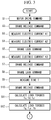
- FIG. 3 is a flowchart for describing the operation of a brake inspection device according to one embodiment of the present invention which is provided to the motor controller in FIG. 1 .
- FIG. 4 is a flowchart which is a continuation of FIG. 3 .
- FIG. 5 is a flowchart showing a modification of FIG. 3 and FIG. 4 .
- FIG. 6 is a flowchart which is a continuation of FIG. 5 .
- FIG. 7 is a flowchart showing another modification of FIG. 3 and FIG. 4 .
- a brake inspection device 11 and a motor controller 1 according to one embodiment of the present invention are described hereinafter with reference to drawings.
- the motor controller 1 is an apparatus which is connected to a motor 4 equipped with a brake 3 mounted on a mechanical unit 2 such as a machine tool, and is configured to control the motor 4 in accordance with a program operation command from the outside of the motor controller 1 .
- the motor controller 1 includes: a speed control unit 6 ; a current control unit 7 ; and the brake inspection device 11 according to this embodiment.
- the speed control unit 6 is configured to control a rotational speed of the motor 4 based on a rotational speed command (or a rotation angle command) for the motor 4 according to a program operation command inputted from the outside of the motor controller 1 , and based on a rotational speed of the motor 4 which is fed back from an encoder 5 .
- the current control unit 7 is configured to control an electric current to be supplied to the motor 4 based on a drive command outputted from the speed control unit 6 .
- a brake control unit 8 is connected to the brake 3 .
- the brake control unit 8 is configured to change over, in response to a command signal from the speed control unit 6 based on the program operation command, between a locked state where a rotor is braked with respect to a stator of the motor 4 and a released state where the locked state is released.
- the brake inspection device 11 includes: a memory unit 12 ; an inspection control unit 13 ; a current measurement unit (load torque measurement unit) 14 ; an arithmetic operation unit (load torque measurement unit) 15 ; a determination unit 16 ; and a notification unit 17 .
- the memory unit 12 is configured to store various constants and the like.
- the inspection control unit 13 is configured to execute an inspection program during control of the motor 4 based on a program operation command.
- the current measurement unit 14 is configured to measure an electric current to be supplied to the motor 4 by the current control unit 7 .
- the arithmetic operation unit 15 is configured to calculate a load torque using an electric current value measured by the current measurement unit 14 .
- the determination unit 16 is configured to determine a state of the brake 3 based on the load torque calculated by the arithmetic operation unit 15 .
- the notification unit 17 is configured to notify an abnormality when any abnormality is present as a result of the determination made by the determination unit 16 .
- the current control unit 7 is configured to control an electric current to be supplied to the motor 4 with the feedback of an electric current value measured by the current measurement unit 14 .
- the inspection control unit 13 is, with the reception of a rotational speed command from the speed control unit 6 , configured to control the current control unit 7 so as to output an electric current value measured by the current measurement unit 14 to the arithmetic operation unit 15 at a predetermined timing, and configured to control the speed control unit 6 so as to output a specific rotational speed command at a predetermined timing.
- the inspection control unit 13 is also configured to control the brake control unit 8 at a predetermined timing.
- Tu denotes a load torque at which the motor 4 is normally rotated in a released state
- Td denotes a load torque at which the motor 4 is reversely rotated in a released state
- Tu′ denotes a load torque at which the motor 4 is driven in a locked state
- Kt denotes a torque constant of the motor 4 stored in the memory unit 12
- a 1 denotes an electric current value at which the motor 4 is normally rotated at a constant speed in a released state
- a 2 denotes an electric current value at which the motor 4 is reversely rotated at a constant speed in a released state
- a 3 denotes an electric current value at which the motor 4 is rotationally driven in a locked state.
- the current measurement unit 14 measures electric current values A 1 , A 2 , A 3 .
- the inspection control unit 13 issues, to the speed control unit 6 , a command to normally rotate (or reversely rotate) the motor 4 with the brake 3 in a locked state and, at the point of time when a speed equal to or more than a predetermined threshold is generated due to the speed feedback from the encoder 5 , the electric current value A 3 is measured by the current measurement unit 14 .
- a speed which reaches 100% of a speed command may be selected as a speed equal to or more than a predetermined threshold, for example.
- an average value between an electric current value as the motor 4 is normally rotated and an electric current value as the motor 4 is reversely rotated may be adopted as the electric current value A 3 .
- the brake inspection device 11 also includes a timer 18 .
- the timer 18 is configured to measure a time T from the point of time when, as shown in FIG. 2 , in a state where the motor 4 is normally rotated with the brake 3 in a released state, the inspection control unit 13 controls the brake control unit 8 so as to change over a state of the brake 3 to a locked state to the point of time when a speed is lowered to a predetermined speed due to a speed feedback.
- a predetermined speed for example, a speed which is lowered to approximately 50% of a speed command may be selected.
- the arithmetic operation unit 15 is configured to calculate load torques Tg, T ⁇ , Tb using the following formulae.
- Tg ( Tu+Td )/2 (4)
- T ⁇ ( Tu ⁇ Td )/2 (5)
- Tb Tu′ ⁇ Tg (6)
- the determination unit 16 is configured to determine states of the brake 3 and the motor 4 using the following formulae. Tg/Tb ⁇ Th 1 (7) T ⁇ /Tb ⁇ Th 2 (8) T ⁇ Th 3 (9)
- Th 1 , Th 2 , Th 3 respectively denote predetermined thresholds.
- Tg denotes a gravity load torque
- T ⁇ denotes a mechanical friction torque
- Tu′ denotes a load torque in a locked state
- Tb denotes a brake holding torque obtained by removing a gravity load torque Tg from a load torque Tu′ in a locked state.
- the formula (7) shows the ratio of the magnitudes of a gravity load torque Tg to a brake holding torque Tb.
- the formula (8) shows the ratio of the magnitudes of a mechanical friction torque T ⁇ to a brake holding torque Tb.
- the determination unit 16 determines that an operation delay abnormality of the brake 3 is present.
- the notification unit 17 When it is determined by the determination unit 16 that an insufficient brake holding torque abnormality, a brake release abnormality or a motor abnormality is present, or when it is determined by the determination unit 16 that an operation delay abnormality of the brake 3 is present, the notification unit 17 notifies such an abnormality.
- any desired method may be adopted such as notification by displaying a letter or an image on a monitor, or by voice or vibration.
- the speed control unit 6 of the motor controller 1 outputs a drive command for the motor 4 (step S 1 ), and outputs an operation command for the brake control unit 8 .
- a rotational speed of the motor 4 is detected by the encoder 5 .
- the rotational speed of the motor 4 is fed back to the speed control unit 6 so that the speed control unit 6 controls a speed of the motor 4 based on the fed back rotational speed and the operation command.
- the current control unit 7 calculates an electric current to be supplied to the motor 4 based on the drive command outputted from the speed control unit 6 . Further, a value of an electric current, which is actually supplied to the motor 4 and is measured by the current measurement unit 14 , is fed back to the current control unit 7 . Accordingly, the current control unit 7 controls an electric current to be supplied to the motor 4 based on the fed back value of the electric current and the drive command.
- the brake control unit 8 outputs a release command for the brake 3 (step S 2 ).
- electric current values A 1 , A 2 as the motor 4 is normally rotated and reversely rotated are outputted to the arithmetic operation unit 15 , wherein the electric current values A 1 , A 2 are measured by the current measurement unit 14 with the mechanical unit 2 disposed at substantially the same position (steps S 3 , S 4 ).
- step S 5 After the electric current values A 1 , A 2 are outputted to the arithmetic operation unit 15 , in a state where the motor 4 is normally rotated with the brake 3 being in a released state, the inspection control unit 13 outputs, to the brake control unit 8 , a command to bring the brake 3 into a locked state (step S 5 ).
- An electric current value A 3 measured at the point of time when a rotational speed fed back from the encoder 5 exceeds a predetermined threshold, is outputted to the arithmetic operation unit 15 from the current measurement unit 14 (step S 6 ).
- the inspection control unit 13 outputs a command to change over a state of the brake 3 to a released state again (step S 7 ).
- the inspection control unit 13 In a state where the motor 4 is normally rotated with the brake 3 in a released state, the inspection control unit 13 outputs, to the brake control unit 8 , a command to bring the brake 3 into a locked state (step S 8 ).
- a time T from the point of time when the command to bring the brake 3 into a locked state is outputted to the point of time when the lowering of a speed is detected is measured (step S 9 ).
- the inspection control unit 13 outputs a command to change over a state of the brake 3 to a released state (step S 10 ).
- Load torques Tu, Td are calculates based on the measured electric current values A 1 , A 2 , and a load torque Tu′ is calculated based on the measured electric current value A 3 (step S 11 ).
- load torques Tg, T ⁇ , Tb are calculated using the measured electric current values A 1 , A 2 , A 3 (step S 12 ).
- a state of the brake 3 and a state of the motor 4 are determined.
- step S 13 it is determined whether or not the formula (7) is satisfied in step S 13 .
- step S 14 it is determined that an insufficient brake holding torque abnormality is present (step S 14 ).
- step S 15 It is determined whether or not the formula (8) is satisfied in step S 15 .
- step S 16 it is determined that a brake release abnormality is present.
- step S 17 it is determined whether or not the formula (9) is satisfied.
- step S 18 it is determined that a motor abnormality is present.
- step S 19 it is determined whether or not a time T is equal to or more than a predetermined threshold Th 4 in step S 19 .
- a time T is equal to or more than the threshold Th 4 , it is determined that a brake operation delay abnormality is present (step S 20 ).
- step S 21 it is determined whether or not an abnormality is determined between step S 13 and step S 20 .
- step S 22 it is determined that the brake 3 and the motor 4 are in a normal state.
- step S 23 it is notified by the notification unit 17 that such an abnormality is present.
- a brake holding torque Tb is calculated by the formula (6) where a gravity load torque Tg is removed from a load torque Tu′ in a locked state.
- a gravity load torque Tg with respect to the brake holding torque Tb is determined by the formula (7).
- a mechanical friction torque T ⁇ with respect to the brake holding torque Tb is determined by the formula (8). Accordingly, there is an advantageous effect that a state of the brake 3 can be accurately determined without being affected by the variation in magnitude of a gravity load torque Tg.
- the description is made with respect to a case where all of the determinations of the formulae (7) to (9) and the determination of a time T are performed.
- the present invention is not limited to such a case. That is, any one of the determinations of the formulae (7) to (9) and the determination of a time T may be performed. Alternatively, any two or more of the determinations of the formulae (7) to (9) and the determination of a time T may be performed in combination. For example, when only the determinations of the formulae (7) to (9) are performed, it is sufficient to perform the operation according to the flowcharts shown in FIG. 5 and FIG. 6 .
- an operation delay abnormality of the brake 3 is determined based on a time T measured by the timer 18 , it is unnecessary to measure an electric current value. Accordingly, an operation delay abnormality of the brake 3 may be individually determined according to the flowchart shown in FIG. 7 .
- a rotational speed of the motor 4 is exemplified as a rotation state of the motor 4 .
- a rotation angle position of the motor 4 may be adopted.
- the determination unit 16 determines that an insufficient brake holding torque abnormality is present when the formula (7) is satisfied.
- the determination unit 16 may determine that an insufficient brake holding torque abnormality is present when the following formula (10) is satisfied.
- Ag is equal to (A 1 +A 2 )/2, and Ab is equal to A 3 ⁇ Ag.
- the determination unit 16 determines that a brake release abnormality is present when the formula (8) is satisfied.
- the determination unit 16 may determine that a brake release abnormality is present when the following formula (11) is satisfied.
- a ⁇ is equal to (A 1 ⁇ A 2 )/2, and Ab is equal to A 3 ⁇ Ag.
- a brake inspection device including: a load torque measurement unit configured to respectively measure: load torques as a motor is normally rotated and reversely rotated in a released state where an operation of a brake for holding a rotor with respect to a stator of the motor is released; and a load torque as the motor is rotationally driven in either one of a normal direction or a reverse direction in a locked state where the brake is operated; and a determination unit configured to determine a state of the brake based on the load torques measured by the load torque measurement unit.
- a load torque of the motor is measured by the load torque measurement unit. Further, in a released state where the operation of the brake is released, a load torque of the motor is measured by the load torque measurement unit.
- a state of the brake is determined by the determination unit based on two load torques. That is, when the brake is in a defective state, for example, when the mechanical unit which releases the operation of the brake is out of order, a load torque measured in a released state increases and approaches a load torque during the operation of the brake.
- a state of the brake can be easily determined based on a load torque measured during the operation of the brake and a load torque measured during the release of the operation of the brake.
- a state of the brake can be accurately detected by measuring both of a load torque during the operation of the brake and a load torque during the release of the operation of the brake and by comparing both load torques with each other.
- Tu denotes a load torque at which the motor is normally rotated in the released state
- Td denotes a load torque at which the motor is reversely rotated in the released state
- Tu′ denotes a load torque at which the motor is driven in the locked state
- Kt denotes a torque constant of the motor
- a 1 denotes an electric current value at which the motor is normally rotated at a constant speed in the released state
- a 2 denotes an electric current value at which the motor is reversely rotated at a constant speed in the released state
- a 3 denotes an electric current value at which the motor is rotationally driven in the locked state.
- a load torque can be calculated in a simple manner based on electric current values measured by the load torque measurement unit by normally rotating and reversely rotating the motor in the released state.
- the load torque measurement unit may measure the load torque at which the motor is normally rotated in the released state and the load torque at which the motor is reversely rotated in the released state with the motor disposed at a same position.
- the load torque measurement unit may measure an electric current value at which the motor is rotationally driven in the locked state upon an increase in position or speed of the motor.
- the determination unit may determine that an insufficient brake holding torque abnormality is present when a following formula is satisfied. Tg/Tb ⁇ Th 1
- Tg is equal to (Tu+Td)/2
- Tb is equal to Tu′ ⁇ Tg
- Th 1 denotes a predetermined threshold
- a brake holding torque is insufficient when a gravity load torque, which is obtained by calculating an average between a load torque as the motor is normally rotated and a load torque as the motor is reversely rotated, is equal to or more than a predetermined value, or when a difference between a load torque at which the brake is in the locked state and the gravity load torque is equal to or smaller than a predetermined value.
- the determination unit may determine that an insufficient brake holding torque abnormality is present when a following formula is satisfied.
- Ag is equal to (A 1 +A 2 )/2
- Ab is equal to A 3 ⁇ Ag
- Th 1 denotes a predetermined threshold.
- the determination unit may determine that a brake release abnormality is present when a following formula is satisfied. T ⁇ /Tb ⁇ Th 2
- T ⁇ is equal to (Tu ⁇ Td)/2
- Tb is equal to Tu′ ⁇ Tg
- Th 2 denotes a predetermined threshold
- a brake release abnormality is present when a mechanical friction torque, which is obtained by calculating a half of a difference between a load torque as the motor is normally rotated and a load torque as the motor is reversely rotated, is equal to or larger than a predetermined value, or when a difference between a load torque at which the brake is in the locked state and the gravity load torque is equal to or smaller than a predetermined value.
- the determination unit may determine that a brake release abnormality is present when a following formula is satisfied.
- a ⁇ is equal to (A 1 ⁇ A 2 )/2
- Ab is equal to A 3 ⁇ Ag
- Th 2 denotes a predetermined threshold.
- Another aspect of the present invention provides a motor controller including any of the above-mentioned brake inspection devices, wherein the determination unit determines that a motor abnormality is present when a following formula is satisfied. T ⁇ Th 3
- T ⁇ is equal to (Tu ⁇ Td)/2
- Th 3 denotes a predetermined threshold
Landscapes
- Physics & Mathematics (AREA)
- General Physics & Mathematics (AREA)
- Engineering & Computer Science (AREA)
- Automation & Control Theory (AREA)
- Control Of Electric Motors In General (AREA)
- Stopping Of Electric Motors (AREA)
- Testing Of Engines (AREA)
- Braking Arrangements (AREA)
Abstract
Description
- {PTL 1} Japanese Unexamined Patent Application, Publication No. Hei6-284766
- {PTL 2} Japanese Unexamined Patent Application, Publication No. 2000-324885
Tu=Kt×A1 (1)
Td=Kt×A2 (2)
Tu′=Kt×A3 (3)
Tg=(Tu+Td)/2 (4)
Tμ=(Tu−Td)/2 (5)
Tb=Tu′−Tg (6)
Tg/Tb≥Th1 (7)
Tμ/Tb≥Th2 (8)
Tμ≥Th3 (9)
Aμ/Ab≥Th1 (10)
Aμ/Ab≥Th2 (11)
Tu=Kt×A1
Td=Kt×A2
Tu′=Kt×A3
Tg/Tb≥Th1
Ag/Ab≥Th1
Tμ/Tb≥Th2
Aμ/Ab≥Th2
Tμ≥Th3
- 1 motor controller
- 3 brake
- 4 motor
- 11 brake inspection device
- 14 current measurement unit (load torque measurement unit)
- 15 arithmetic operation unit (load torque measurement unit)
- 16 determination unit
Claims (9)
Tu=Kt×A1
Td=Kt×A2
Tu′=Kt×A3
Tg/Tb≥Th1
Ag/Ab≥Th1
Tμ/Tb≥Th2
Aμ/Ab≥Th2
Tμ≥Th3
Applications Claiming Priority (2)
| Application Number | Priority Date | Filing Date | Title |
|---|---|---|---|
| JP2017137152A JP6856465B2 (en) | 2017-07-13 | 2017-07-13 | Brake inspection device and motor control device |
| JP2017-137152 | 2017-07-13 |
Publications (2)
| Publication Number | Publication Date |
|---|---|
| US20190017890A1 US20190017890A1 (en) | 2019-01-17 |
| US10859455B2 true US10859455B2 (en) | 2020-12-08 |
Family
ID=64745320
Family Applications (1)
| Application Number | Title | Priority Date | Filing Date |
|---|---|---|---|
| US16/009,809 Active 2039-05-03 US10859455B2 (en) | 2017-07-13 | 2018-06-15 | Brake inspection device and motor controller |
Country Status (4)
| Country | Link |
|---|---|
| US (1) | US10859455B2 (en) |
| JP (1) | JP6856465B2 (en) |
| CN (1) | CN109254574B (en) |
| DE (1) | DE102018211153A1 (en) |
Families Citing this family (10)
| Publication number | Priority date | Publication date | Assignee | Title |
|---|---|---|---|---|
| JP6382882B2 (en) * | 2016-04-15 | 2018-08-29 | ファナック株式会社 | Brake inspection device and brake inspection method |
| JP7414462B2 (en) * | 2019-10-18 | 2024-01-16 | ファナック株式会社 | Machine tools and their brake inspection methods |
| CN114667677B (en) * | 2019-11-19 | 2022-10-28 | 三菱电机株式会社 | Motor drive control device and motor drive control system |
| CN111037605A (en) * | 2019-12-26 | 2020-04-21 | 中科新松有限公司 | A wear detection method for electromagnetic brakes of robot joints |
| DE102020205379A1 (en) * | 2020-04-28 | 2021-10-28 | Kuka Deutschland Gmbh | Method for detecting and evaluating a state of friction on a joint, robot arm and computer program product |
| CN112008761B (en) * | 2020-08-27 | 2022-01-11 | 中科新松有限公司 | Brake module with brake detection function and brake function detection method |
| CN112008762B (en) * | 2020-08-27 | 2022-02-01 | 中科新松有限公司 | Fully-sealed brake module with double-channel detection function and detection method |
| DE102021202612A1 (en) | 2021-03-18 | 2022-09-22 | Continental Teves Ag & Co. Ohg | Method for monitoring the release behavior of an electromechanical wheel brake of a vehicle |
| JPWO2024105725A1 (en) * | 2022-11-14 | 2024-05-23 | ||
| CN117484512B (en) * | 2023-12-29 | 2024-04-05 | 苏州钧舵机器人有限公司 | Electric clamping jaw control method and electric clamping jaw |
Citations (17)
| Publication number | Priority date | Publication date | Assignee | Title |
|---|---|---|---|---|
| JPH06284766A (en) | 1993-03-30 | 1994-10-07 | Toshiba Corp | Motor with brake |
| JP3081258B2 (en) | 1991-02-19 | 2000-08-28 | 帝人製機株式会社 | Brake failure detection method |
| JP2000324885A (en) | 1999-05-12 | 2000-11-24 | Amada Co Ltd | Method and apparatus for detecting brake failure of servo motor with brake |
| JP2005254410A (en) | 2004-03-12 | 2005-09-22 | Kawasaki Heavy Ind Ltd | Braking performance detection method and braking performance detection device |
| US20100058850A1 (en) | 2008-09-08 | 2010-03-11 | Tobias Ortmaier | Method to test a brake of a robot |
| JP2014227233A (en) | 2013-05-20 | 2014-12-08 | 株式会社日立製作所 | Elevator with safety device |
| US20150123577A1 (en) * | 2013-11-05 | 2015-05-07 | Denso Corporation | Control apparatus for ac motor |
| JP2015108764A (en) | 2013-12-05 | 2015-06-11 | コニカミノルタ株式会社 | Image forming device |
| US9260094B2 (en) * | 2012-05-28 | 2016-02-16 | Advics Co., Ltd. | Vehicle brake device |
| EP3025828A1 (en) | 2014-11-28 | 2016-06-01 | Kabushiki Kaisha Yaskawa Denki | Brake diagnosis device and brake diagnosis method |
| US20160346885A1 (en) | 2015-05-29 | 2016-12-01 | Fanuc Corporation | Motor control system provided with function to detect abnormal braking and method of detecting abnormal braking |
| US20170033714A1 (en) | 2015-07-31 | 2017-02-02 | Fanuc Corporation | Braking apparatus having function of detecting brake actuation and release faults |
| US20170108071A1 (en) | 2015-10-14 | 2017-04-20 | Fanuc Corporation | Motor drive apparatus equipped with life prediction function for motor brake |
| US9694688B2 (en) * | 2012-08-30 | 2017-07-04 | Hitachi Automotive Systems, Ltd. | Electric vehicle drive system |
| US9744862B2 (en) * | 2011-09-28 | 2017-08-29 | Continental Teves Ag & Co. Ohg | Slip-controlled braking system for electrically driven motor vehicles |
| JP2017192267A (en) | 2016-04-15 | 2017-10-19 | ファナック株式会社 | Brake inspection apparatus and brake inspection method |
| US10352383B2 (en) * | 2014-07-18 | 2019-07-16 | Ntn Corporation | Electric brake device |
Family Cites Families (4)
| Publication number | Priority date | Publication date | Assignee | Title |
|---|---|---|---|---|
| WO1996003744A1 (en) * | 1994-07-27 | 1996-02-08 | Sony Corporation | Diagnosis of machine or apparatus, and apparatus therefor |
| JP2012144345A (en) * | 2011-01-13 | 2012-08-02 | Toshiba Elevator Co Ltd | Method for diagnosing elevator brake torque |
| JP5602186B2 (en) * | 2012-05-28 | 2014-10-08 | マイクロスペース株式会社 | Motor drive control device |
| JP6377985B2 (en) * | 2014-07-24 | 2018-08-22 | ファナック株式会社 | Motor control device with torque command limiting function during power failure |
-
2017
- 2017-07-13 JP JP2017137152A patent/JP6856465B2/en active Active
-
2018
- 2018-06-15 US US16/009,809 patent/US10859455B2/en active Active
- 2018-07-06 DE DE102018211153.7A patent/DE102018211153A1/en active Pending
- 2018-07-10 CN CN201810751187.7A patent/CN109254574B/en active Active
Patent Citations (24)
| Publication number | Priority date | Publication date | Assignee | Title |
|---|---|---|---|---|
| JP3081258B2 (en) | 1991-02-19 | 2000-08-28 | 帝人製機株式会社 | Brake failure detection method |
| JPH06284766A (en) | 1993-03-30 | 1994-10-07 | Toshiba Corp | Motor with brake |
| JP2000324885A (en) | 1999-05-12 | 2000-11-24 | Amada Co Ltd | Method and apparatus for detecting brake failure of servo motor with brake |
| JP2005254410A (en) | 2004-03-12 | 2005-09-22 | Kawasaki Heavy Ind Ltd | Braking performance detection method and braking performance detection device |
| US20100058850A1 (en) | 2008-09-08 | 2010-03-11 | Tobias Ortmaier | Method to test a brake of a robot |
| KR20130099237A (en) | 2008-09-08 | 2013-09-05 | 쿠카 레보라토리즈 게엠베하 | Method for checking a brake of a robot and method for use of torque detected by a torque sensor to check a brake of a robot |
| US9744862B2 (en) * | 2011-09-28 | 2017-08-29 | Continental Teves Ag & Co. Ohg | Slip-controlled braking system for electrically driven motor vehicles |
| US9260094B2 (en) * | 2012-05-28 | 2016-02-16 | Advics Co., Ltd. | Vehicle brake device |
| US9694688B2 (en) * | 2012-08-30 | 2017-07-04 | Hitachi Automotive Systems, Ltd. | Electric vehicle drive system |
| JP2014227233A (en) | 2013-05-20 | 2014-12-08 | 株式会社日立製作所 | Elevator with safety device |
| US20150123577A1 (en) * | 2013-11-05 | 2015-05-07 | Denso Corporation | Control apparatus for ac motor |
| US20150160595A1 (en) | 2013-12-05 | 2015-06-11 | Konica Minolta, Inc. | Image forming apparatus |
| JP2015108764A (en) | 2013-12-05 | 2015-06-11 | コニカミノルタ株式会社 | Image forming device |
| US10352383B2 (en) * | 2014-07-18 | 2019-07-16 | Ntn Corporation | Electric brake device |
| US20160156288A1 (en) * | 2014-11-28 | 2016-06-02 | Kabushiki Kaisha Yaskawa Denki | Brake diagnosis device and brake diagnosis method |
| JP2016101643A (en) | 2014-11-28 | 2016-06-02 | 株式会社安川電機 | Brake diagnostic system and method for diagnosis of brake |
| EP3025828A1 (en) | 2014-11-28 | 2016-06-01 | Kabushiki Kaisha Yaskawa Denki | Brake diagnosis device and brake diagnosis method |
| US20160346885A1 (en) | 2015-05-29 | 2016-12-01 | Fanuc Corporation | Motor control system provided with function to detect abnormal braking and method of detecting abnormal braking |
| US20170033714A1 (en) | 2015-07-31 | 2017-02-02 | Fanuc Corporation | Braking apparatus having function of detecting brake actuation and release faults |
| JP2017034856A (en) | 2015-07-31 | 2017-02-09 | ファナック株式会社 | Brake device having a function of detecting brake operation and release abnormality |
| US20170108071A1 (en) | 2015-10-14 | 2017-04-20 | Fanuc Corporation | Motor drive apparatus equipped with life prediction function for motor brake |
| JP2017074837A (en) | 2015-10-14 | 2017-04-20 | ファナック株式会社 | Motor drive device with motor brake life prediction function |
| JP2017192267A (en) | 2016-04-15 | 2017-10-19 | ファナック株式会社 | Brake inspection apparatus and brake inspection method |
| US20170299452A1 (en) | 2016-04-15 | 2017-10-19 | Fanuc Corporation | Brake inspection device and brake inspection method |
Non-Patent Citations (3)
| Title |
|---|
| Japan Patent Office, Office Action dated Apr. 23, 2019 for Japan Patent Application No. 2017-137152. |
| Japan Patent Office, Office Action dated Mar. 20, 2018 for Japan Patent Application No. 2016-082220. |
| Japan Patent Office, Search Report dated Apr. 18, 2019 for Japan Patent Application No. 2017-137152. |
Also Published As
| Publication number | Publication date |
|---|---|
| DE102018211153A1 (en) | 2019-01-17 |
| JP2019022281A (en) | 2019-02-07 |
| US20190017890A1 (en) | 2019-01-17 |
| JP6856465B2 (en) | 2021-04-07 |
| CN109254574B (en) | 2023-01-10 |
| CN109254574A (en) | 2019-01-22 |
Similar Documents
| Publication | Publication Date | Title |
|---|---|---|
| US10859455B2 (en) | Brake inspection device and motor controller | |
| JP6294262B2 (en) | Abnormality detection device having abnormality detection function of machine tool and abnormality detection method | |
| JP5694481B1 (en) | Motor control device for detecting abnormality of power transmission part between main shaft and motor | |
| CN107298088B (en) | Brake verification device and brake verification method | |
| US9694456B2 (en) | Motor control system provided with function to detect abnormal braking and method of detecting abnormal braking | |
| US10454401B2 (en) | Motor controller | |
| US20160169755A1 (en) | Cogging torque measuring apparatus for motor | |
| JP6312645B2 (en) | Motor driving apparatus capable of reporting abnormal operation of fan and method thereof | |
| US10081088B2 (en) | Main spindle failure detection device for machine tool and method of detecting main spindle failure | |
| JP2008176559A (en) | Control unit | |
| TWI660162B (en) | Motor controlling device and motor device using the same | |
| JP2019110628A (en) | Servo motor load state diagnostic device, and load state diagnostic method thereof | |
| US20230173678A1 (en) | Method for detecting and evaluating a friction status at a joint, robotic arm and computer program product | |
| JP2011063404A (en) | Door control device of elevator | |
| WO2018083739A1 (en) | Elevator device and calibration method for weighing device | |
| US9692348B2 (en) | Motor control device that detects overload | |
| JP5240846B2 (en) | Fan monitoring and control device | |
| US9356550B2 (en) | Motor controller having abnormality detection function of power transmission unit between motor and main shaft | |
| US10668603B2 (en) | Impulse wrench rotation detection | |
| JP2006170741A (en) | Abnormality detector for motive power measurement system | |
| JP6892029B1 (en) | Motor drive control device and motor drive control system | |
| JP2016090454A (en) | Blake torque measurement device |
Legal Events
| Date | Code | Title | Description |
|---|---|---|---|
| AS | Assignment |
Owner name: FANUC CORPORATION, JAPAN Free format text: ASSIGNMENT OF ASSIGNORS INTEREST;ASSIGNORS:ONO, KATSUYA;UEMATSU, HIDETOSHI;TAMAKI, TAKESHI;REEL/FRAME:046101/0611 Effective date: 20180327 |
|
| FEPP | Fee payment procedure |
Free format text: ENTITY STATUS SET TO UNDISCOUNTED (ORIGINAL EVENT CODE: BIG.); ENTITY STATUS OF PATENT OWNER: LARGE ENTITY |
|
| STPP | Information on status: patent application and granting procedure in general |
Free format text: APPLICATION DISPATCHED FROM PREEXAM, NOT YET DOCKETED |
|
| STPP | Information on status: patent application and granting procedure in general |
Free format text: DOCKETED NEW CASE - READY FOR EXAMINATION |
|
| STPP | Information on status: patent application and granting procedure in general |
Free format text: NON FINAL ACTION MAILED |
|
| STPP | Information on status: patent application and granting procedure in general |
Free format text: RESPONSE TO NON-FINAL OFFICE ACTION ENTERED AND FORWARDED TO EXAMINER |
|
| STPP | Information on status: patent application and granting procedure in general |
Free format text: PUBLICATIONS -- ISSUE FEE PAYMENT VERIFIED |
|
| STCF | Information on status: patent grant |
Free format text: PATENTED CASE |
|
| MAFP | Maintenance fee payment |
Free format text: PAYMENT OF MAINTENANCE FEE, 4TH YEAR, LARGE ENTITY (ORIGINAL EVENT CODE: M1551); ENTITY STATUS OF PATENT OWNER: LARGE ENTITY Year of fee payment: 4 |