US10859415B2 - Flow measurement apparatus and method of use - Google Patents
Flow measurement apparatus and method of use Download PDFInfo
- Publication number
- US10859415B2 US10859415B2 US15/573,122 US201615573122A US10859415B2 US 10859415 B2 US10859415 B2 US 10859415B2 US 201615573122 A US201615573122 A US 201615573122A US 10859415 B2 US10859415 B2 US 10859415B2
- Authority
- US
- United States
- Prior art keywords
- sleeve
- flow
- fluid
- flow path
- measurement apparatus
- Prior art date
- Legal status (The legal status is an assumption and is not a legal conclusion. Google has not performed a legal analysis and makes no representation as to the accuracy of the status listed.)
- Active, expires
Links
- 238000005259 measurement Methods 0.000 title claims abstract description 188
- 238000000034 method Methods 0.000 title claims abstract description 38
- 239000012530 fluid Substances 0.000 claims abstract description 242
- 238000006073 displacement reaction Methods 0.000 claims abstract description 123
- 230000007246 mechanism Effects 0.000 claims description 37
- 230000002093 peripheral effect Effects 0.000 claims description 37
- 230000008859 change Effects 0.000 claims description 18
- 238000004891 communication Methods 0.000 claims description 13
- 238000011144 upstream manufacturing Methods 0.000 claims description 11
- 230000003628 erosive effect Effects 0.000 claims description 8
- 238000000576 coating method Methods 0.000 claims description 6
- 239000011248 coating agent Substances 0.000 claims description 5
- 230000000694 effects Effects 0.000 claims description 3
- 239000007789 gas Substances 0.000 description 9
- 238000004519 manufacturing process Methods 0.000 description 8
- PXHVJJICTQNCMI-UHFFFAOYSA-N Nickel Chemical compound [Ni] PXHVJJICTQNCMI-UHFFFAOYSA-N 0.000 description 2
- 210000001124 body fluid Anatomy 0.000 description 2
- 239000010839 body fluid Substances 0.000 description 2
- 230000008878 coupling Effects 0.000 description 2
- 238000010168 coupling process Methods 0.000 description 2
- 238000005859 coupling reaction Methods 0.000 description 2
- 238000010586 diagram Methods 0.000 description 2
- 230000006870 function Effects 0.000 description 2
- 239000000463 material Substances 0.000 description 2
- 239000011343 solid material Substances 0.000 description 2
- 239000002699 waste material Substances 0.000 description 2
- XLYOFNOQVPJJNP-UHFFFAOYSA-N water Substances O XLYOFNOQVPJJNP-UHFFFAOYSA-N 0.000 description 2
- VYZAMTAEIAYCRO-UHFFFAOYSA-N Chromium Chemical compound [Cr] VYZAMTAEIAYCRO-UHFFFAOYSA-N 0.000 description 1
- 208000027418 Wounds and injury Diseases 0.000 description 1
- 230000004913 activation Effects 0.000 description 1
- QVGXLLKOCUKJST-UHFFFAOYSA-N atomic oxygen Chemical compound [O] QVGXLLKOCUKJST-UHFFFAOYSA-N 0.000 description 1
- 230000000740 bleeding effect Effects 0.000 description 1
- 238000009530 blood pressure measurement Methods 0.000 description 1
- 238000005234 chemical deposition Methods 0.000 description 1
- 238000005229 chemical vapour deposition Methods 0.000 description 1
- 230000006378 damage Effects 0.000 description 1
- 230000001419 dependent effect Effects 0.000 description 1
- 238000001514 detection method Methods 0.000 description 1
- 230000007717 exclusion Effects 0.000 description 1
- 239000000446 fuel Substances 0.000 description 1
- 208000014674 injury Diseases 0.000 description 1
- 239000007788 liquid Substances 0.000 description 1
- 229910052751 metal Inorganic materials 0.000 description 1
- 239000002184 metal Substances 0.000 description 1
- 238000012544 monitoring process Methods 0.000 description 1
- 229910052759 nickel Inorganic materials 0.000 description 1
- 230000003287 optical effect Effects 0.000 description 1
- 239000001301 oxygen Substances 0.000 description 1
- 229910052760 oxygen Inorganic materials 0.000 description 1
- 238000007747 plating Methods 0.000 description 1
- 231100000614 poison Toxicity 0.000 description 1
- 230000007096 poisonous effect Effects 0.000 description 1
- 230000004044 response Effects 0.000 description 1
- 239000004576 sand Substances 0.000 description 1
- 239000007921 spray Substances 0.000 description 1
- 231100000331 toxic Toxicity 0.000 description 1
- 230000002588 toxic effect Effects 0.000 description 1
- UONOETXJSWQNOL-UHFFFAOYSA-N tungsten carbide Chemical compound [W+]#[C-] UONOETXJSWQNOL-UHFFFAOYSA-N 0.000 description 1
- 230000000007 visual effect Effects 0.000 description 1
- 238000003466 welding Methods 0.000 description 1
Images


Classifications
-
- G—PHYSICS
- G01—MEASURING; TESTING
- G01F—MEASURING VOLUME, VOLUME FLOW, MASS FLOW OR LIQUID LEVEL; METERING BY VOLUME
- G01F1/00—Measuring the volume flow or mass flow of fluid or fluent solid material wherein the fluid passes through a meter in a continuous flow
- G01F1/05—Measuring the volume flow or mass flow of fluid or fluent solid material wherein the fluid passes through a meter in a continuous flow by using mechanical effects
- G01F1/20—Measuring the volume flow or mass flow of fluid or fluent solid material wherein the fluid passes through a meter in a continuous flow by using mechanical effects by detection of dynamic effects of the flow
- G01F1/22—Measuring the volume flow or mass flow of fluid or fluent solid material wherein the fluid passes through a meter in a continuous flow by using mechanical effects by detection of dynamic effects of the flow by variable-area meters, e.g. rotameters
-
- G—PHYSICS
- G01—MEASURING; TESTING
- G01F—MEASURING VOLUME, VOLUME FLOW, MASS FLOW OR LIQUID LEVEL; METERING BY VOLUME
- G01F1/00—Measuring the volume flow or mass flow of fluid or fluent solid material wherein the fluid passes through a meter in a continuous flow
- G01F1/05—Measuring the volume flow or mass flow of fluid or fluent solid material wherein the fluid passes through a meter in a continuous flow by using mechanical effects
- G01F1/34—Measuring the volume flow or mass flow of fluid or fluent solid material wherein the fluid passes through a meter in a continuous flow by using mechanical effects by measuring pressure or differential pressure
- G01F1/36—Measuring the volume flow or mass flow of fluid or fluent solid material wherein the fluid passes through a meter in a continuous flow by using mechanical effects by measuring pressure or differential pressure the pressure or differential pressure being created by the use of flow constriction
- G01F1/40—Details of construction of the flow constriction devices
-
- G—PHYSICS
- G01—MEASURING; TESTING
- G01F—MEASURING VOLUME, VOLUME FLOW, MASS FLOW OR LIQUID LEVEL; METERING BY VOLUME
- G01F1/00—Measuring the volume flow or mass flow of fluid or fluent solid material wherein the fluid passes through a meter in a continuous flow
- G01F1/05—Measuring the volume flow or mass flow of fluid or fluent solid material wherein the fluid passes through a meter in a continuous flow by using mechanical effects
- G01F1/20—Measuring the volume flow or mass flow of fluid or fluent solid material wherein the fluid passes through a meter in a continuous flow by using mechanical effects by detection of dynamic effects of the flow
- G01F1/22—Measuring the volume flow or mass flow of fluid or fluent solid material wherein the fluid passes through a meter in a continuous flow by using mechanical effects by detection of dynamic effects of the flow by variable-area meters, e.g. rotameters
- G01F1/26—Measuring the volume flow or mass flow of fluid or fluent solid material wherein the fluid passes through a meter in a continuous flow by using mechanical effects by detection of dynamic effects of the flow by variable-area meters, e.g. rotameters of the valve type
-
- G—PHYSICS
- G01—MEASURING; TESTING
- G01F—MEASURING VOLUME, VOLUME FLOW, MASS FLOW OR LIQUID LEVEL; METERING BY VOLUME
- G01F1/00—Measuring the volume flow or mass flow of fluid or fluent solid material wherein the fluid passes through a meter in a continuous flow
- G01F1/05—Measuring the volume flow or mass flow of fluid or fluent solid material wherein the fluid passes through a meter in a continuous flow by using mechanical effects
- G01F1/34—Measuring the volume flow or mass flow of fluid or fluent solid material wherein the fluid passes through a meter in a continuous flow by using mechanical effects by measuring pressure or differential pressure
- G01F1/36—Measuring the volume flow or mass flow of fluid or fluent solid material wherein the fluid passes through a meter in a continuous flow by using mechanical effects by measuring pressure or differential pressure the pressure or differential pressure being created by the use of flow constriction
- G01F1/40—Details of construction of the flow constriction devices
- G01F1/44—Venturi tubes
-
- G—PHYSICS
- G01—MEASURING; TESTING
- G01F—MEASURING VOLUME, VOLUME FLOW, MASS FLOW OR LIQUID LEVEL; METERING BY VOLUME
- G01F15/00—Details of, or accessories for, apparatus of groups G01F1/00 - G01F13/00 insofar as such details or appliances are not adapted to particular types of such apparatus
- G01F15/001—Means for regulating or setting the meter for a predetermined quantity
-
- G—PHYSICS
- G01—MEASURING; TESTING
- G01F—MEASURING VOLUME, VOLUME FLOW, MASS FLOW OR LIQUID LEVEL; METERING BY VOLUME
- G01F15/00—Details of, or accessories for, apparatus of groups G01F1/00 - G01F13/00 insofar as such details or appliances are not adapted to particular types of such apparatus
- G01F15/005—Valves
-
- G—PHYSICS
- G01—MEASURING; TESTING
- G01F—MEASURING VOLUME, VOLUME FLOW, MASS FLOW OR LIQUID LEVEL; METERING BY VOLUME
- G01F1/00—Measuring the volume flow or mass flow of fluid or fluent solid material wherein the fluid passes through a meter in a continuous flow
- G01F1/05—Measuring the volume flow or mass flow of fluid or fluent solid material wherein the fluid passes through a meter in a continuous flow by using mechanical effects
- G01F1/20—Measuring the volume flow or mass flow of fluid or fluent solid material wherein the fluid passes through a meter in a continuous flow by using mechanical effects by detection of dynamic effects of the flow
- G01F1/32—Measuring the volume flow or mass flow of fluid or fluent solid material wherein the fluid passes through a meter in a continuous flow by using mechanical effects by detection of dynamic effects of the flow using swirl flowmeters
- G01F1/3209—Measuring the volume flow or mass flow of fluid or fluent solid material wherein the fluid passes through a meter in a continuous flow by using mechanical effects by detection of dynamic effects of the flow using swirl flowmeters using Karman vortices
-
- G—PHYSICS
- G01—MEASURING; TESTING
- G01F—MEASURING VOLUME, VOLUME FLOW, MASS FLOW OR LIQUID LEVEL; METERING BY VOLUME
- G01F1/00—Measuring the volume flow or mass flow of fluid or fluent solid material wherein the fluid passes through a meter in a continuous flow
- G01F1/05—Measuring the volume flow or mass flow of fluid or fluent solid material wherein the fluid passes through a meter in a continuous flow by using mechanical effects
- G01F1/34—Measuring the volume flow or mass flow of fluid or fluent solid material wherein the fluid passes through a meter in a continuous flow by using mechanical effects by measuring pressure or differential pressure
- G01F1/36—Measuring the volume flow or mass flow of fluid or fluent solid material wherein the fluid passes through a meter in a continuous flow by using mechanical effects by measuring pressure or differential pressure the pressure or differential pressure being created by the use of flow constriction
- G01F1/40—Details of construction of the flow constriction devices
- G01F1/42—Orifices or nozzles
-
- G—PHYSICS
- G01—MEASURING; TESTING
- G01F—MEASURING VOLUME, VOLUME FLOW, MASS FLOW OR LIQUID LEVEL; METERING BY VOLUME
- G01F1/00—Measuring the volume flow or mass flow of fluid or fluent solid material wherein the fluid passes through a meter in a continuous flow
- G01F1/05—Measuring the volume flow or mass flow of fluid or fluent solid material wherein the fluid passes through a meter in a continuous flow by using mechanical effects
- G01F1/34—Measuring the volume flow or mass flow of fluid or fluent solid material wherein the fluid passes through a meter in a continuous flow by using mechanical effects by measuring pressure or differential pressure
- G01F1/36—Measuring the volume flow or mass flow of fluid or fluent solid material wherein the fluid passes through a meter in a continuous flow by using mechanical effects by measuring pressure or differential pressure the pressure or differential pressure being created by the use of flow constriction
- G01F1/40—Details of construction of the flow constriction devices
- G01F1/46—Pitot tubes
-
- G—PHYSICS
- G01—MEASURING; TESTING
- G01F—MEASURING VOLUME, VOLUME FLOW, MASS FLOW OR LIQUID LEVEL; METERING BY VOLUME
- G01F1/00—Measuring the volume flow or mass flow of fluid or fluent solid material wherein the fluid passes through a meter in a continuous flow
- G01F1/56—Measuring the volume flow or mass flow of fluid or fluent solid material wherein the fluid passes through a meter in a continuous flow by using electric or magnetic effects
- G01F1/58—Measuring the volume flow or mass flow of fluid or fluent solid material wherein the fluid passes through a meter in a continuous flow by using electric or magnetic effects by electromagnetic flowmeters
-
- G—PHYSICS
- G01—MEASURING; TESTING
- G01F—MEASURING VOLUME, VOLUME FLOW, MASS FLOW OR LIQUID LEVEL; METERING BY VOLUME
- G01F1/00—Measuring the volume flow or mass flow of fluid or fluent solid material wherein the fluid passes through a meter in a continuous flow
- G01F1/66—Measuring the volume flow or mass flow of fluid or fluent solid material wherein the fluid passes through a meter in a continuous flow by measuring frequency, phase shift or propagation time of electromagnetic or other waves, e.g. using ultrasonic flowmeters
- G01F1/663—Measuring the volume flow or mass flow of fluid or fluent solid material wherein the fluid passes through a meter in a continuous flow by measuring frequency, phase shift or propagation time of electromagnetic or other waves, e.g. using ultrasonic flowmeters by measuring Doppler frequency shift
-
- G—PHYSICS
- G01—MEASURING; TESTING
- G01F—MEASURING VOLUME, VOLUME FLOW, MASS FLOW OR LIQUID LEVEL; METERING BY VOLUME
- G01F1/00—Measuring the volume flow or mass flow of fluid or fluent solid material wherein the fluid passes through a meter in a continuous flow
- G01F1/68—Measuring the volume flow or mass flow of fluid or fluent solid material wherein the fluid passes through a meter in a continuous flow by using thermal effects
-
- G—PHYSICS
- G01—MEASURING; TESTING
- G01F—MEASURING VOLUME, VOLUME FLOW, MASS FLOW OR LIQUID LEVEL; METERING BY VOLUME
- G01F1/00—Measuring the volume flow or mass flow of fluid or fluent solid material wherein the fluid passes through a meter in a continuous flow
- G01F1/76—Devices for measuring mass flow of a fluid or a fluent solid material
- G01F1/78—Direct mass flowmeters
- G01F1/80—Direct mass flowmeters operating by measuring pressure, force, momentum, or frequency of a fluid flow to which a rotational movement has been imparted
- G01F1/84—Coriolis or gyroscopic mass flowmeters
-
- G—PHYSICS
- G01—MEASURING; TESTING
- G01F—MEASURING VOLUME, VOLUME FLOW, MASS FLOW OR LIQUID LEVEL; METERING BY VOLUME
- G01F1/00—Measuring the volume flow or mass flow of fluid or fluent solid material wherein the fluid passes through a meter in a continuous flow
- G01F1/76—Devices for measuring mass flow of a fluid or a fluent solid material
- G01F1/86—Indirect mass flowmeters, e.g. measuring volume flow and density, temperature or pressure
- G01F1/90—Indirect mass flowmeters, e.g. measuring volume flow and density, temperature or pressure with positive-displacement meter or turbine meter to determine the volume flow
Definitions
- the present invention is a 35 U.S.C. ⁇ 371 U.S. National Stage of International Application No. PCT/GB2016/051543, filed on May 27, 2016, which claims priority to Great Britain Patent Application No. 1509334.7, filed May 29, 2015, the entire content of each of which is incorporated herein by reference.
- the present invention relates to a flow measurement apparatus and a method of use, and particular to flow measurement apparatus used to measure fluid flow rates in oil and gas industry systems. Aspects of the invention relate to an apparatus and method for measuring a flow rate in a production flow stream.
- One particular type of flow meter is a differential pressure flow meter which relies on the Bernoulli principle.
- the Bernoulli principle states that an increase in the speed of a fluid occurs simultaneously with a decrease in the pressure of the fluid.
- These measurement devices measure the differential pressure induced in the fluid as it flows through a constriction or around an obstacle in the fluid conduit. The flow rate of the fluid may then be accurately determined from the pressure difference.
- differential pressure flow meters are designed and calibrated for a specific fluid type and have a predetermined flow rate range.
- the fluid flow rate may vary considerably and may be outside the predetermined range that the meter is capable of accurately measuring. This may lead to inaccurate flow measurements or in some cases the flow meter not measuring the flow rate at all.
- a known method of changing flow rate measurement range of a flow meter is to change the dimensions of the constriction or obstacle to change the beta ratio of the flow meter.
- the beta ratio is the ratio of the diameter of the constriction or obstacle to the fluid conduit diameter.
- US 2012/0096949 discloses a device for changing a beta ratio of a flow measurement device.
- the device includes a flange and a sleeve extending axially from the flange.
- the sleeve may be inserted into a fluid conduit of the flow measurement device to reduce the inner diameter of the fluid conduit around a fluid displacement member.
- a disadvantage of the device described in US 2012/0096949 is that it requires the removal and replacement of components of the system from the pipeline which requires that the entire pipeline pressure to be bled off. This may result in flammable and potentially toxic fluids being released into the atmosphere around the pipeline. In addition, the pipeline bleeding operation can be time consuming and expensive especially if the pipeline is large and if the monetary value of the expelled fluid is high.
- fluid After reinstalling the measurement apparatus, fluid must be re-introduced slowly into the pipeline to ensure no leaks occur. During this operation the system production line must be offline, resulting in lost revenue and/or rig time.
- U.S. Pat. No. 5,404,758 discloses a flow meter device for determining the amount of flowing medium using an orifice and a resistor body in a cavity through which the medium to be measured flows.
- the orifice sleeve is displaced as a consequence of the varying primary pressure and the degree of opening of the flow orifice is determined depending on the amount of flow of the flowing medium.
- the flow meter device described in U.S. Pat. No. 5,404,758 has the disadvantage that it is not possible to accurately monitor the position of the orifice sleeve relative to the resistor during use of the flow meter.
- the position of the sleeve varies as the pressure of the fluid acting on the orifice sleeve changes. This limits the accuracy of the flow meter as precise measurement of the flow area is required to accurately determine a given flow rate. If the exact position of the orifice sleeve is unknown then calculation may be based on an incorrect beta ratio value. Failure to accurately measure the flow rate could have safety and financial impacts on oil and gas operations.
- a flow measurement apparatus comprising:
- a meter body comprising a throughbore with a fluid flow path
- a sleeve movably mounted within the fluid flow path
- the sleeve is configured to be movable between at least two axial positions within the fluid flow path to select a predetermined flow rate measurement range for the flow measurement apparatus.
- the above invention may facilitate a wide range of flow rates to be quickly and accurately measured by moving the sleeve to different axial positions in the fluid flow path and thereby changing the fluid flow area and/or beta ratio of the flow measurement apparatus.
- the sleeve may be set at different axial positions within the fluid flow path.
- the sleeve may be set at predetermined axial positions within the fluid flow path to allow a range of beta ratio values to be set in the flow measurement apparatus.
- the beta ratio can be reliably set and accurate flow rate measurement readings may be calculated. This may allow the user to select the most applicable measurement range (i.e. high range or low range) for the meter apparatus while the system and/or flowline is online and/or pressurised.
- the sleeve is configured to be slidably mounted within the fluid flow path.
- the sleeve may be any annular shape.
- the inner diameter of the sleeve may be smaller than the inner diameter of the meter body bore.
- the sleeve may be configured to change the diameter of the fluid flow path of the meter body throughbore.
- the diameter of the fluid flow path and the sleeve may be dimensioned to measure a range of flow rates.
- the sleeve is configured to move relative to the flow displacement member to change the flow area around the flow displacement member.
- the sleeve is configured to move relative to the flow displacement member to change the inner diameter of the bore surrounding the flow displacement member.
- the sleeve may be axially displaced away from the flow displacement member such that the flow area around the flow displacement member has the inner diameter of the meter body throughbore.
- the sleeve may surround the flow displacement member such that flow area around the flow displacement member has the inner diameter of the sleeve.
- the sleeve may have a range of sizes and/or shaped profiles.
- the sleeve may have an entrance throat section and/or an exit throat section.
- the entrance and/or exit throat sections may have an inclined, tapered or stepped profile.
- the stepped profile may comprise a series of steps.
- the inner diameter of each step of the entrance throat section and/or an exit throat section of the sleeve may have a predetermined diameter which may be different to the inner diameter of the other steps of the throat section and/or the inner diameter of the sleeve.
- the flow measurement apparatus may be a pitot tube, venturi, vortex, orifice, ultrasonic, turbine, nozzle, rotameter, calorimetric, electromagnetic, magnetic, Doppler, thermal, coriolis and/or pressure differential flow meter.
- the flow measurement apparatus is a pressure differential flow meter.
- a mechanism is configured to accurately adjust, control and/or set the axial position of the sleeve in the fluid flow path.
- the mechanism is located outside the fluid flow path.
- the mechanism may be selected from a linear motion, rotary motion, reciprocating motion and/or oscillating motion actuator.
- the mechanism may be selected from springs, levers, cams, cranks, screws, gears, pistons and/or pulleys.
- the gears may include spur, rack and pinion, bevel and/or worm gears.
- a component of the mechanism may extend into the fluid flow path to engage the sleeve.
- the component of the mechanism may comprise springs, levers, cams, cranks, screws, gears, pistons, pulleys and/or an actuator arm.
- the meter body may comprise an aperture configured to allow a component of the mechanism to extend into the fluid flow path of the meter body throughbore to engage and/or couple the sleeve.
- the mechanism may be manually, hydraulically, pneumatically, electrically or mechanically actuated.
- the fluid may be oil, gas, steam, water, waste product or any other suitable fluid.
- the meter body may have connectors such as flanges at each end to secure the meter body to a section of pipe work.
- the meter body may be clamped, bolted and/or welded to a section of pipe work.
- the flow displacement member is a conical cone.
- the flow displacement member may have a first diverging section and second converging section.
- the interface between diverging and converging section may form a peripheral edge.
- the flow displacement member may be positioned centrally in the fluid flow path.
- the flow displacement member may be supported by at least one support member.
- the distance between the peripheral edge of the displacement member and the inner diameter of the meter body throughbore, inner diameter of the sleeve and/or a inner diameter of the throat section of the sleeve may define a flow area and/or beta ratio.
- the ratio of the diameter of the peripheral edge of the displacement member to an inner diameter of the meter body throughbore or an inner diameter of the sleeve may define a beta ratio of the measurement apparatus.
- the ratio of diameter of the peripheral edge of the displacement member to an inner diameter of the sleeve throat section may define a beta ratio of the measurement apparatus.
- the cone may be hollow or made from a solid material.
- the cone may be made from a flat plate which is rolled to form a cone shape.
- the sleeve may be formed from metal, plastic, or any suitable material.
- the sleeve has an erosion resistant coating.
- the erosion resistant coating may comprise chrome plating, chemical deposition and/or welded overlay coatings such as InconelTM.
- the erosion resistant coating may comprise tungsten carbide or a nickel plated layer.
- the erosion resistant coating may be applied using a chemical vapour deposition or high velocity oxygen fuel spray technique.
- the meter body throughbore may have an inner diameter approximately the same as the inner diameter of pipe work to which the flow measurement apparatus is connected.
- the flow measurement apparatus may be connected to a control unit to monitor the fluid flow rates.
- the control unit may monitor the position of the sleeve.
- the control unit may control and/or set the position of the sleeve.
- seals are provided between the outer surface of the sleeve and the inner surface of the fluid flow path of the meter body to prevent fluid egress between the outer surface of the sleeve and the inner surface of the fluid flow path.
- a flow measurement apparatus comprising
- a meter body comprising a throughbore with a fluid flow path
- a sleeve movably mounted within the fluid flow path
- a mechanism operable to effect axial movement of the sleeve between at least two axial positions within the fluid flow path to select a predetermined flow rate measurement range.
- a flow measurement apparatus with a movable sleeve which is capable of being axially moved between at least two axial positions within the fluid flow path different flow areas may be provided in the fluid flow path which may facilitate the accurate measurement of different flow rate ranges. This may provide a flow measurement apparatus with increased reliability, accuracy and efficiency.
- the mechanism is configured to allow accurate positioning of the sleeve in the fluid flow path.
- the use of a mechanism to control and/or set the positioning of the sleeve from outside the fluid flow path avoids dismantling of the apparatus to select a different flow rate measurement range.
- the sleeve is configured to be axially moved from a first position to at least a second position within the fluid flow path.
- the sleeve is configured to at least partially enclose the flow displacement member when it is in the first or/and at least second position.
- the flow displacement member comprises a conical cone.
- the flow displacement member may have a first diverging section and second converging section.
- the interface between diverging and converging section may form a peripheral edge.
- a first flow area and/or first beta ratio is defined by the distance between the peripheral edge of the displacement member and the inner diameter of the meter body throughbore fluid flow path.
- a second flow area and/or first beta ratio is defined by the distance between the peripheral edge of the displacement member and the inner diameter of the sleeve and/or the inner diameter of a throat section of the sleeve.
- a first beta ratio is defined by the ratio of the diameter of the peripheral edge of the displacement member to the inner diameter of the meter body throughbore fluid flow path.
- a second beta ratio is defined by the ratio of the diameter of the peripheral edge of the displacement member to the inner diameter of the sleeve and/or the inner diameter of a throat section of the sleeve.
- the mechanism is located outside the fluid flow path and is configured to accurately control and set the axial position of the sleeve in the fluid flow path.
- the mechanism may be manually, hydraulically, pneumatically, electrically or mechanically actuated.
- the apparatus comprises at least one sensor to accurately detect and/or determine the position of the sleeve within the fluid flow path.
- the at least one sensor may be selected from a potentiometer, ohmmeter, gauss meter, ultrasonic sensor and/or distance encoder.
- the mechanism may be configured to monitor and/or track the axial position of the sleeve in the fluid flow path.
- the mechanism may be coupled to an indicator and/or display to indicate the position of the sleeve.
- the apparatus comprises a control unit.
- the control unit is configured to receive information from the at least one sensor.
- the control unit is configured be programmable.
- the control unit may comprise adjustable settings to be calibrated for specific parameters of the fluid, fluid properties, meter body throughbore and the sleeve including flow pressure, differential pressure between an upstream pressure and downstream pressure of a displacement member, flow temperature, sleeve type and dimensions and sleeve mechanism type.
- control unit is configured to activate an alarm.
- the alarm may be activated if the sleeve is detected in an incorrect axial position within the fluid flow path or if the sleeve and/or mechanism have not completely moved from the first position to the at least second position.
- the fluid may be oil, gas, steam, water, waste product or any other suitable fluid.
- Embodiments of the second aspect of the invention may include one or more features of the first aspect of the invention or its embodiments, or vice versa.
- a flow measurement apparatus comprising:
- a meter body comprising a throughbore with a fluid flow path
- a sleeve movably mounted within the fluid flow path
- the method may comprise obtaining a beta ratio value for the flow measurement apparatus at the first and/or at least second position.
- the method may comprise calculating a beta ratio value for a desired flow rate measurement and/or flow rate measurement range.
- the method may comprise determining the axial position of the sleeve required to obtain the desired flow rate measurement and/or flow rate measurement range.
- the method may comprise moving the axial position of the sleeve within the fluid flow path of the meter body throughbore to the second position which may be the determined axial position of the sleeve required to obtain the desired flow rate measurement and/or flow rate measurement range.
- the method may comprise setting the axial position of the sleeve at this second position.
- Embodiments of the third aspect of the invention may comprise features corresponding to the preferred or optional features of the first or second aspects of the invention or vice versa.
- a flow measurement apparatus comprising:
- a meter body comprising a throughbore with a fluid flow path
- a sleeve movably mounted within the fluid flow path
- the method may comprise detecting and/or identifying the axial position of the sleeve within the fluid flow path at a first axial position.
- the method may comprise detecting and/or identifying the axial position of the sleeve within the fluid flow path of the meter body throughbore at a second axial position.
- the method may comprise obtaining a beta ratio value for the flow measurement apparatus at a first and/or second axial position.
- the method may comprise calculating the mass and volume flow rate of the fluid at a first and/or second axial position.
- the method may comprise calculating a beta ratio value for a desired flow rate measurement and/or flow rate measurement range.
- the method may comprise determining the axial position of the sleeve required to obtain the desired flow rate measurement and/or flow rate measurement range and moving the sleeve axially within the fluid conduit to an axial position within the fluid flow path to change the flow rate measurement range to the desired flow rate measurement range.
- Embodiments of the fourth aspect of the invention may comprise features corresponding to the preferred or optional features of the first, second or third aspects of the invention or vice versa.
- a flow measurement apparatus comprising a
- a meter body comprising a throughbore with a fluid flow path
- the method may comprise detecting and/or identifying the axial position of the sleeve within the fluid conduit at a first position.
- the method may comprise detecting and/or identifying the axial position of the sleeve within the fluid conduit at a second position.
- the method may comprise obtaining a beta ratio value for the flow measurement apparatus at a first and/or second position.
- the method may comprise calculating the mass and volume flow rate of the fluid at a first and/or second position.
- the method may comprise calculating a beta ratio value for a desired flow rate measurement and/or flow rate measurement range.
- the method may comprise determining the axial position of the sleeve within the meter body throughbore fluid flow path required to obtain the desired flow rate measurement and/or flow rate measurement range and actuating the mechanism to move the sleeve axially within the fluid flow path to an axial position within the fluid flow path to change the flow rate measurement range to the desired flow rate measurement range.
- Embodiments of the fifth aspect of the invention may comprise features corresponding to the preferred or optional features of the first to fourth aspects of the invention or vice versa.
- FIGS. 1A and 1B are longitudinal sectional schematic views of a flow measurement apparatus according to a first embodiment of the invention
- FIGS. 2A to 2I are longitudinal sectional schematic views of a flow measurement apparatus according to a second embodiment of the invention.
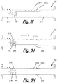
- FIGS. 3A to 3K are longitudinal sectional schematic views of a flow measurement apparatus according to a third embodiment of the invention.
- FIGS. 4A and 4B are longitudinal sectional schematic views of a flow measurement apparatus according to a fourth embodiment of the invention.
- FIGS. 5A and 5B are longitudinal sectional schematic views of a flow measurement apparatus according to a fifth embodiment of the invention.
- FIGS. 6 a to 6 O are longitudinal sectional schematic views of a flow measurement apparatus according to a sixth embodiment of the invention.
- FIG. 7 is block diagram representing steps of calculating the flow rate of a fluid in a production pipeline.
- FIGS. 1A and 1B show longitudinal sectional schematic views of flow measurement apparatus 10 according to a first embodiment of the invention.
- the flow measurement apparatus 10 can be seen to comprise a meter body 11 having a throughbore 11 a with a fluid flow path 12 through which fluid is configured to flow.
- the apparatus 10 is configured to be installed and/or connected in a pipeline structure.
- Flanges 13 are located at the ends of the meter body 11 and are configured to be secured to a pipeline structure (not shown) via bolts or any other affixing manner such as welding if the material is suitable. Seals 19 are provided between the flange sections 13 and the fluid flow path 12
- a flow displacement member 14 is centrally disposed in the fluid flow path 12 and suspended from the meter body 11 via a support 16 .
- the flow displacement member 14 is configured to introduce a pressure difference between the fluid upstream of the displacement member 14 and the fluid downstream.
- the profile shape of the displacement member is configured to induce a pressure drop in the fluid as it passes over the displacement member in the fluid flow path.
- the displacement member 14 comprises a diverging cone section 14 a and a converging cone section 14 b . This is a one example and alternative shaped displacement members suitable for creating a pressure differential in the fluid may be used.
- the flow displacement member 14 is manufactured from a flat plate, which is rolled and welded to produce a hollow rolled flat plate conical shape. This rolled plate cone is configured to be less likely to vibrate during flowing conditions. Alternatively, the flow displacement member may be machined from solid material.
- the flow displacement member may optionally be supported by an additional support member 16 a to reduce vibration of the flow displacement member during fluid flow.
- the flow measurement apparatus 10 has a first pressure outlet 20 and a second pressure outlet 22 .
- the first pressure outlet 20 is configured to be in fluid communication with the fluid flow path 12 at a position upstream of the flow displacement member.
- the second pressure outlet 22 is connected to an interior passageway 24 which extends through the flow displacement member 14 and the support member 16 .
- the second pressure outlet 22 is configured to be in fluid communication with the fluid flow path 12 at a position downstream of the flow displacement member via the interior passageway of the flow displacement member 14 and the support member 16 .
- An annular sleeve 30 is slidably mounted in the fluid flow path 12 .
- the sleeve is configured to move axially between a first and at least a second position. Although it is shown in FIGS. 1A and 1B that the sleeve is moved between a first ( FIG. 1A ) a second ( FIG. 1B ) position, intermediate positions between these positions may be selected.
- the sleeve 30 has an outer diameter and the inner diameter.
- the sleeve is dimensioned such that it is able to slide axially within the inner diameter of the meter body throughbore 11 a.
- Seals 36 are positioned between the outer surface of the sleeve 30 and the inner surface of the throughbore 11 a to prevent fluid egress between the outer surface of the sleeve and the inner surface of the throughbore 11 a.
- the sleeve 30 comprises a rack section 32 which is configured to mesh with a gear pinion 38 connected to a drive mechanism 40 .
- the gear pinion 38 is configured to extend through a slot 39 in the meter body to mesh with the rack section 32 to axially move the annular sleeve 30 within the fluid flow path 12 .
- annular sleeve 30 is located in a first position which is at its outermost extended position from the displacement member 14 .
- the flow area of the fluid is defined by the peripheral edge 45 of the displacement member and the inner diameter of the throughbore 11 a.
- FIG. 1B the annular sleeve 30 has been moved to a second position which partially encloses the displacement member 14 within the flow path 12 .
- the flow area of the fluid is defined by the peripheral edge 45 of the displacement member and the inner diameter of the annular sleeve 30 .
- the sleeve 30 has an inner diameter which is smaller than the inner diameter of the throughbore 11 a . This means that the beta ratio of the measurement apparatus has been reduced when the sleeve is moved to the second position.
- the flow measurement range of the apparatus depends on the beta ratio value of the apparatus.
- the beta ratio value is the ratio of the diameter of the peripheral edge of flow displacement member and the inner diameter of the throughbore 11 a .
- the beta ratio value is the ratio of the diameter of the peripheral edge of flow displacement member and the inner diameter of the sleeve.
- Q m mass flow rate at the flowing pressure P f and flowing temperature T f
- Q v volume flow rate at the flowing pressure P f and flowing temperature T f
- X 3 constant values, determined by the chosen units of measurement.
- ⁇ P Differential Pressure across the meter
- P f Fluid absolute pressure at the upstream pressure tap.
- k Gas Isentropic Exponent
- ⁇ tp Fluid density at flowing conditions.
- Each beta ratio value has a corresponding Coefficient of discharge, which is used along with the measured parameters of Differential Pressure, Flowing Pressure and Temperature to calculate the mass and volume flow rate of the flowing fluid.
- a simple visual pointer may be connected to the sleeve and/or the mechanism to detect where the axial position of the sleeve in the fluid flow path.
- a distance encoder sensor such as an optical rotary encoder may be connected to the sleeve and/or the mechanism. This sensor provides real-time position feedback of the position of the sleeve.
- a graduation scale may be engraved on along the surface of the sleeve to identify the axial position of the sleeve.
- FIGS. 2A to 2I show longitudinal sectional schematic views of flow measurement apparatus 100 according to a second embodiment of the invention.
- the flow measurement apparatus 100 is similar to the apparatus 10 and will be understood from FIGS. 1A and 1B and the accompanying description.
- flow measurement apparatus 100 has an alternative mechanism used to control the axial movement and positioning of the sleeve.
- the flow measurement apparatus 100 can be seen to comprise a meter body 111 having a throughbore 111 a with a fluid flow path 112 through which fluid is configured to flow.
- An annular sleeve 130 is slidably mounted in the fluid flow path 112 .
- the sleeve 130 comprises a series of blind bore holes 132 which are configured to engage locator bolts 108 a and 108 b .
- the blind holes are arranged on the outer surface of the sleeve 130 and do not extend through the inner surface of the sleeve 130 .
- the distance between the series of the blind bore holes 132 is configured to locate the sleeve in predetermined positions within the fluid flow path.
- the entrance throat 134 to the sleeve has a smooth tapered surface.
- the meter body 111 comprises a hatch section 102 with a removable hatch cover 104 .
- the hatch cover 104 comprises boreholes 106 through which locator bolts 108 a and 108 b may extend and securely engage the blind bore holes 132 of the sleeve 130 .
- a first high range beta ratio position shown in FIG. 2A the sleeve is at the outermost extended position downstream from the displacement member 114 .
- the flow area of the fluid and/or the beta ratio of the measurement apparatus is defined by the peripheral edge 145 of the displacement member and the inner diameter of the throughbore 111 a .
- the meter is capable of measuring a high range of flow rate.
- the sleeve is located downstream of the displacement member at a distance equal or greater than the diameter of the throughbore 111 a and/or the diameter of the pipework to which the apparatus is connected.
- a second low range beta ratio position shown in FIG. 2I the sleeve partially encloses the displacement member 114 within the flow path 112 .
- the flow area of the fluid and/or the beta ratio of the measurement apparatus is defined by the peripheral edge 145 of the displacement member and the inner diameter of the annular sleeve 130 .
- the sleeve 130 has an inner diameter which is smaller than the inner diameter of the throughbore 111 a .
- the meter is capable of measuring a low range of flow rate.
- FIGS. 2C to 2I show the stages of adjusting the axial position of the sleeve 130 in the flow path from the first to the second position.
- Locator bolt 108 a is removed from the hatch section 102 and secured in blind borehole 132 b of the sleeve 130 .
- the locator bolt 108 a is pulled generally in direction show as arrow X to axially move the sleeve axially closer to the displacement member within the fluid flow path as shown in FIG. 2D
- the locator bolt 108 a is removed from the blind borehole 132 b of the sleeve 130 and subsequently secured in blind borehole 132 c .
- the locator bolt 108 a is again pulled generally in direction show as arrow X to axially move the sleeve within the fluid flow path as shown in FIG. 2F .
- the locator bolt 108 a is removed from the blind borehole 132 c of the sleeve 130 and subsequently secured in blind borehole 132 d .
- the locator bolt 108 a is pulled in a direction show as arrow X to axially move the sleeve within the fluid flow path as shown in FIG. 2H .
- the locator bolt 108 a is removed from the blind borehole 132 d of the sleeve 130 .
- the hatch cover is secured to the hatch section of the fluid flow path.
- Locator bolts 108 a and 108 b are secured through the boreholes of the hatch cover and are secured in blind boreholes 132 c and 132 d of the sleeve 130 to secure the sleeve in the second position.
- a potentiometer or magnetic position sensor may be used to accurately determine the position of sleeve within the flow path.
- a graduation scale may be engraved along the surface of the sleeve to identify the axial position of the sleeve within the fluid flow path and/or relative to the displacement member. The graduation scale and therefore the axial position of the sleeve may observed through the hatch section 102 .
- FIGS. 3A to 3K show longitudinal section schematic views of flow measurement apparatus 200 according to a third embodiment of the invention.
- the flow measurement apparatus 200 is similar to the apparatus 10 and will be understood from FIGS. 1A and 1B and the accompanying description.
- flow measurement apparatus 200 has an alternative sleeve throat section profile.
- the flow measurement apparatus 200 can be seen to comprise a meter body 211 having a throughbore 211 a with a fluid flow path 212 through which fluid is configured to flow.
- a sleeve 230 comprises a series of blind bore holes 232 which are configured to engage locator bolts 208 and 208 b .
- the blind bore holes are arranged on the outer surface of the sleeve 230 and do not extend through to the inner surface of the sleeve 230 .
- the distance between the series of the blind bore holes 232 is configured to locate the sleeve in predetermined positions within the fluid flow path relative to a displacement member 214 .
- the meter body 211 comprises a hatch section 202 with a removable hatch cover 204 .
- the hatch cover 204 comprises boreholes 206 through which locator bolts 208 may extend and securely engage the blind bore holes 232 of the sleeve 230 .
- the entrance throat 250 of the sleeve comprises a series of relatively short, inward aligned steps 250 a and 250 b .
- the stepped entrance throat is configured to gradually reduce the inner diameter of sleeve from the inner diameter of the outer step 250 a of the entrance throat of the sleeve to the inner diameter of the sleeve.
- three stepped diameters 250 a , 250 b and the inner diameter of the sleeve can be seen.
- any other number of stepped diameters may be used.
- the sleeve In a first position shown in FIG. 3A the sleeve is at the outermost extended position downstream from the displacement member 214 . In this first position the flow area of the fluid is defined by the peripheral edge 245 of the displacement member and the inner diameter of the throughbore 211 a . To avoid erosion of the sleeve during use of the meter in this first position the sleeve is located downstream of the displacement member at a distance equal or greater than the diameter of the throughbore 111 a and/or the diameter of the pipework to which the apparatus is connected.
- FIGS. 3A to 3I show the stages of adjusting the beta ratio of the flow measurement apparatus by changing the axial position of the sleeve 230 in the flow path.
- the hatch cover 204 is removed from the hatch section 202 by removing fixing bolts (not shown).
- Locator bolt 208 a is removed from the hatch section 202 and secured in blind borehole 232 b of the sleeve 230 .
- the locator bolt 208 a is pulled in a direction show as arrow X to axially move the sleeve to a position closer to the flow displacement member.
- the locator bolt 208 a is removed from the blind borehole 232 b of the sleeve 230 and subsequently secured in blind borehole 232 c .
- the locator bolt 208 a is pulled in a direction show as arrow X to axially move the sleeve within the fluid flow path to a second position as shown in FIG. 3E .
- the sleeve is positioned around the flow displacement member such that the peripheral edge 245 of the displacement member and the inner diameter of the first step 250 a of the throat section of the annular sleeve 230 define flow area of the fluid.
- the first step 250 a has an inner diameter which is smaller than the inner diameter of the throughbore 211 a . This means that the beta ratio of the measurement apparatus has been reduced when the sleeve is moved from the first position as shown in FIG. 3A to the second position as shown in FIG. 3E .
- the locator bolt 208 a is removed from the blind borehole 232 c of the sleeve 230 .
- the hatch cover is secured to the hatch section.
- Locator bolts 208 a and 208 b are secured through the boreholes of the hatch cover and are secured in blind boreholes 232 c and 232 e of the sleeve 230 to secure the sleeve in this second position.
- Locator bolt 208 a is removed from the hatch section 202 and secured in blind borehole 232 d .
- the locator bolt 208 a is pulled in a general direction show as arrow X to axially move the sleeve within the fluid flow path from a second position to a third position.
- the sleeve is positioned around the flow displacement member such that the peripheral edge 245 of the displacement member and the inner diameter of the second step 250 b of the throat section of the annular sleeve define a flow area for the fluid.
- the second step 250 b has an inner diameter which is smaller than the inner diameter of the first step 250 a of the throat section of the sleeve. This means that the beta ratio of the measurement apparatus has been reduced when the sleeve is moved from the second position to a third position.
- the locator bolt 208 a is removed from the blind borehole 232 c of the sleeve 230 .
- the hatch cover 204 is secured to the hatch section 202 .
- Locator bolts 208 a and 208 b are secured through the boreholes of the hatch cover and are secured in blind boreholes 232 d and 232 f of the sleeve 230 to secure the sleeve in this third position.
- Locator bolt 208 a is removed from the hatch section 202 and secured in blind borehole 232 e .
- the locator bolt 208 a is pulled in a direction show as arrow X to axially move the sleeve within the fluid flow path from a third position to a fourth position.
- the sleeve is positioned around the flow displacement member such that the peripheral edge 245 of the displacement member and the inner diameter of the sleeve define a flow area for the fluid.
- the inner diameter of the sleeve has a diameter which is smaller than the inner diameter of the second step 250 b of the throat section of the sleeve. This means that the beta ratio of the measurement apparatus has been reduced when the sleeve is moved from the third position to the fourth position.
- the locator bolt 208 a is removed from the blind borehole 232 e of the sleeve 230 .
- the hatch cover is secured to the hatch section.
- Locator bolts 208 a and 208 b are secured through the boreholes of the hatch cover and are secured in blind boreholes 232 e and 232 g of the sleeve 230 to secure the sleeve in this fourth position.
- An externally mounted resistor or magnetic type position indicator may be used to accurately indicate the position of the sleeve in the fluid flow path.
- an externally mounted resistor may be configured to provide a different resistance reading when the sleeve is located in each of the first to fourth positions.
- the resistor may be configured to have a resistance reading of between 1 and 1.5 Ohms when the sleeve is located in the first position where the flow area of the fluid is defined by the peripheral edge 245 of the displacement member and the inner diameter of the meter body throughbore 211 a.
- the resistor may be configured to have a resistance reading of between 2.0 to 2.5 Ohms when the sleeve is located in the second position where the sleeve is positioned around the flow displacement member such that the peripheral edge 245 of the displacement member and the inner diameter of the first step 250 a of the throat section of the annular sleeve 230 define flow area of the fluid.
- the resistor may be configured to have a resistance reading of between 3.0 to 3.5 Ohms when the sleeve is positioned around the flow displacement member such that the peripheral edge 245 of the displacement member and the inner diameter of the second step 250 b of the throat section of the annular sleeve define a flow area for the fluid.
- the resistor may be configured to have a resistance reading of between 4.0 to 4.5 Ohms when the sleeve is positioned around the flow displacement member such that the peripheral edge 245 of the displacement member and the inner diameter of the sleeve define a flow area for the fluid.
- the control unit may be configured to ignore flow readings when the sleeve is located midway between the any of the predetermined first to fourth positions and only measure flow readings when positioned at the first to fourth positions. Therefore, reading will only be measured if the resistor reading is between 1 and 1.5 Ohms, 2 and 2.5 Ohms, 3 and 3.5 Ohms, 4 and 4.5 Ohms and will be ignored at all other resistance levels to mitigate inaccurate measurements when the sleeve is in one of the correct positions.
- the above resistance readings are provided as an example and alternative resistor readings and/or settings may be used. It will be clear that certain selected above steps may be reversed to the change the position of the sleeve from the fourth to the first positions or intermediate positions therebetween.
- FIGS. 4A and 4B shows longitudinal section schematic views of flow measurement apparatus 300 according to a fourth embodiment of the invention.
- the flow measurement apparatus 300 is similar to the apparatus 10 and will be understood from FIGS. 1A and 1B and the accompanying description.
- flow measurement apparatus 300 has an alternative mechanism used to control the axial movement of the sleeve.
- the flow measurement apparatus 300 can be seen to comprise a meter body 311 having a throughbore 311 a with a fluid flow path 312 through which fluid is configured to flow.
- the flow path 312 comprises a hatch section 302 through which a coupling 320 of an actuator arm 321 extends.
- the sleeve 330 is connected to the coupling 320 such that activation of the actuator arm 321 axially moves the sleeve axially within the fluid flow path.
- the actuator arm 321 is configured to move between an innermost retracted position as shown in FIG. 4A and an outermost extended position as shown in FIG. 4B .
- the arm 321 may be moved to an intermediate position between the innermost retracted position and outermost extended positions.
- FIG. 4A the annular sleeve 330 is shown in a first position where the actuator arm 321 is retracted to its innermost position such that the sleeve is axially displaced away from the displacement member 314 .
- the flow area of the fluid is defined by the peripheral edge 345 of the displacement member and the inner diameter of the fluid flow path of throughbore 311 a of the meter body.
- This provides a first beta ratio valve for the measurement apparatus which allows a first range of flow rates to be measured.
- FIG. 4B the annular sleeve 330 is shown in a second position where the actuator arm 321 is extended to it outermost position such that the sleeve 330 partially encloses the displacement member 314 within the flow path 312 .
- the flow area of the fluid is defined by the peripheral edge 345 of the displacement member and the inner diameter of the annular sleeve 330 .
- the sleeve 330 has an inner diameter which is smaller than the inner diameter of the throughbore 311 a . This provides a second beta ratio of the measurement apparatus which allows a second range of flow rates to be measured.
- FIGS. 5A and 5B shows longitudinal section schematic views of flow measurement apparatus 400 according to a fifth embodiment of the invention.
- the flow measurement apparatus 300 is similar to the apparatus 10 and will be understood from FIGS. 1A and 1B and the accompanying description.
- flow measurement apparatus 400 has an alternative mechanism used to control the axial movement of the sleeve.
- the flow measurement apparatus 400 can be seen to comprise a meter body 411 having a throughbore 411 a with a fluid flow path 412 through which fluid is configured to flow.
- the meter body 411 comprises a first pressure port 402 and a second pressure port 404 .
- the first pressure port 402 is configured to be in fluid communication with a first differential fluid area 406 defined by the outer surface 416 of the sleeve 430 , a raised edge 417 a of the outer surface of the sleeve 430 and a stepped channel 407 on the inner surface of the throughbore 411 a of the meter body.
- the second pressure port 404 is in fluid communication with a second differential fluid area 408 defined by the outer surface 416 of the sleeve 430 , a raised edge 417 b of the outer surface of the sleeve 430 and a stepped channel 407 on the inner surface of the throughbore 411 a of the meter body.
- the first pressure port 402 and the first differential fluid area 404 are operable to function as a pressure activated piston to move the sleeve 430 in a first direction generally shown as arrow Y.
- the second pressure port 404 and the second differential fluid area are operable to function as a pressure activated piston to move the sleeve is a second direction generally shown as arrow Z.
- a pressure source (not shown) is applied to the first pressure port 402 .
- the increase in pressure acts on the differential area 406 and moves the annular sleeve to a first position shown in FIG. 5A , such that the sleeve is axially displaced away from the displacement member 414 .
- the flow area of the fluid is defined by the peripheral edge 445 of the displacement member and the inner diameter of the throughbore 411 a .
- the throughbore 411 a has an inner diameter which is larger than the inner diameter of the sleeve. This provides a first beta ratio value of the measurement apparatus which allows a first range of flow rates to be measured.
- a pressure source (not shown) is applied to the second pressure port 404 .
- the increase in pressure acts on the differential area 408 and moves the annular sleeve axially within fluid flow path to a second position shown in FIG. 5B , such that the sleeve partially encloses the displacement member 414 within the flow path 412 .
- the flow area of the fluid is defined by the peripheral edge 445 of the displacement member and the inner diameter of the annular sleeve 430 .
- the sleeve 430 has an inner diameter which is smaller than the inner diameter of the meter body throughbore 411 a . This provides a second beta ratio value for the measurement apparatus which allows a second range of flow rates to be measured.
- a spring such as metallic or gas spring may be coupled between the meter body and the annular sleeve to act as a fail-safe mechanism to move the sleeve to a predetermined safe position in the event of a leak in the pressure source.
- FIGS. 6A to 6K show longitudinal sectional schematic views of flow measurement apparatus 500 according to a sixth embodiment of the invention.
- the flow measurement apparatus 500 is similar to the apparatus 200 and will be understood from FIGS. 3A to 3K and the accompanying description.
- flow measurement apparatus 500 has an alternative sleeve throat section profile.
- the flow measurement apparatus 500 can be seen to comprise a meter body 511 having a throughbore 511 a with a fluid flow path 512 through which fluid is configured to flow.
- the sleeve 530 comprises a series of blind bore holes 532 which are configured to engage locator bolts 508 .
- the blind bore holes are arranged on the outer surface of the sleeve 530 and do not extend through to the inner surface of the sleeve 530 .
- the distance between the series of the blind bore holes 532 is configured to locate the sleeve in predetermined positions within the fluid flow path relative to a displacement member 514 .
- the entrance throat 550 to the sleeve is tapered.
- the tapered throat is configured to gradually reduce the inner diameter of sleeve from the inner diameter of the outer edge of the entrance throat of the sleeve to the inner diameter of the sleeve.
- the sleeve In a first position shown in FIG. 6A the sleeve is at the outermost extended position downstream from the displacement member 514 . In this first position the flow area of the fluid is defined by the peripheral edge 545 of the displacement member and the inner diameter of the meter throughbore 511 a . To avoid erosion of the sleeve during fluid flow in this first position the sleeve is located downstream of the displacement member at a distance equal or greater than the diameter of the pipe.
- FIGS. 6A to 6N show the stages of adjusting the beta ratio of the flow measurement apparatus by changing the axial position of the sleeve 530 in the flow path.
- a hatch cover 504 is removed from a hatch section 502 on the meter body 511 by removing fixing bolts.
- the locator bolt 508 a may engage blind boreholes 532 a to 532 l of the sleeve 530 and may be pulled in a direction show as arrow X to axially move the sleeve 530 within the fluid flow path 512 in a similar manner as described in the description of FIGS. 3A to 3K .
- the sleeve is positioned in a second position where the sleeve is located partially around flow displacement member such that the peripheral edge 545 of the displacement member 514 and the inner diameter of the opening edge of the throat section of the annular sleeve 530 define flow area of the fluid.
- the opening edge of the throat section of the annular sleeve 530 has an inner diameter which is slightly smaller than the inner diameter of the meter body throughbore 511 a . This means that the beta ratio of the measurement apparatus has been reduced when the sleeve is moved from the first position shown in FIG. 6A to the second position shown in FIG. 6E .
- the hatch cover 504 and locator bolts 508 a and 508 b may be secured through the boreholes and blind boreholes 532 c and 532 e as shown in FIG. 6F .
- the sleeve is moved from the second position to a third position shown in FIG. 6H .
- the locator bolt 508 a engages blind borehole 532 e of the sleeve 530 and is pulled in a direction show as arrow X to axially move the sleeve within the fluid flow path from a second position to a third position.
- the sleeve is positioned around the flow displacement member such that flow area defined by the peripheral edge 545 of the displacement member and the inner diameter of the throat section is smaller than the flow area in the second position as shown in FIG. 6H .
- This means that the beta ratio of the measurement apparatus has been reduced when the sleeve is moved from the second position to the third position. The change in the beta ratio allows the measurement apparatus to measure a different flow rate range.
- the hatch cover 504 and locator bolts 508 a and 508 b may secured through the boreholes and blind boreholes 532 d and 532 f as shown in FIG. 6I .
- the sleeve is moved from the third position to a fourth position shown in FIG. 6K .
- the locator bolt 508 a engages blind borehole 532 f of the sleeve 530 and is pulled in a direction show as arrow X to axially move the sleeve within the fluid flow path from a third position to a fourth position.
- the sleeve is positioned around the flow displacement member such that flow area defined by the peripheral edge 545 of the displacement member and the inner diameter of the throat section is smaller than the flow area in the third position as shown in FIG. 6K .
- the hatch cover 504 and locator bolts 508 a and 508 b may secured through the boreholes and blind boreholes 532 e and 532 g as shown in FIG. 6L .
- the sleeve is moved from the fourth position to a fifth position shown in FIG. 6N .
- the locator bolt 508 a engages blind borehole 532 f of the sleeve 530 and is pulled generally in a direction show as arrow X to axially move the sleeve within the fluid flow path from a fourth position to a fifth position.
- the sleeve is positioned around the flow displacement member such that the peripheral edge 545 of the displacement member and the inner diameter of the sleeve 530 define a flow area of the fluid.
- the inner diameter of the sleeve is smaller than the sleeve throat section as shown in FIG. 6N . This means that the beta ratio of the measurement apparatus has been reduced when the sleeve is moved from the fourth position to the fifth position.
- the locator bolt 508 a is removed from the blind borehole 532 f of the sleeve 530 .
- the hatch cover is secured to the hatch section of the meter body.
- Locator bolts 508 a and 508 b are secured through the boreholes of the hatch cover and are secured in blind boreholes 532 e and 532 g of the sleeve 530 to secure the sleeve in this fifth position.
- a control unit is programmable and has adjustable settings to allow the measurement apparatus to be calibrated for specific parameters of the fluid, meter body and the sleeve including flow pressure, differential pressure between an upstream and downstream of a displacement member, flow temperature, fluid properties, sleeve type and dimensions, meter body throughbore dimensions, displacement member dimensions and sleeve mechanism type.
- parameters including fluid properties (Step 601 ), flow pressure levels (Step 602 ) and temperature levels (Step 603 ) are measured and communicated to a control unit.
- control unit is able to calculate the fluid base density, flowing density, base compressibility and flowing compressibility of the fluid (Step 604 ).
- Pressure measurement readings of the differential pressure between an upstream and downstream of the displacement member are communicated to the control unit. These readings are time stamped and logged by the control unit.
- a beta ratio for the measurement device is calculated based on the position of the sleeve within the flow path.
- the precise axial position of the sleeve within the meter body bore flow path is communicated to the control unit where a real time beta ratio is calculated.
- the position of the sleeve may be entered into the control unit manually by the user setting its position or automatically by the position of the sleeve being detected using position detection sensors to determine the sleeve position (Step 606 ).
- the beta ratio and coefficient of discharge values are calculated from preset tables parameters including inner diameter of the meter body throughbore, inner diameter of the sleeve and/or inner diameter of a sleeve throat section, beta ratio and coefficient of discharge value for the corresponding preset position of the sleeve within the fluid flow path of the meter body (Step 607 ).
- the control unit calculates the mass and volume flow rate of the fluid (Step 608 ). If the flow of fluid falls to a level outside the range of the measurement apparatus the user moves and sets a new axially position of sleeve within the fluid flow path of the meter body. Alternatively the control unit may be configured to move the sleeve to a new axially position. The new position of the sleeve is communicated to the control unit where a real time beta ratio is calculated. The new sleeve position produces a change in the beta ratio of the measurement apparatus which adjusts the flow rate measurement range of the apparatus. Using the calculated real time beta ratio the control unit calculates the mass and volume flow rate of the fluid.
- the control unit displays parameters such as differential pressure readings, pressure readings, temperature, flowing density, flowing compressibility, sleeve position in the meter body fluid flow path, mass and volume flow rate, beta ratio, coefficient of discharge, inner diameter of the meter body throughbore, inner diameter of the sleeve and/or inner diameter of a sleeve throat section for the user to verify that the calculation is being carried correctly (Step 609 ).
- the control unit stores or logs the apparatus, fluid and flow parameters to memory for later assessment or use by the user. This data may be assessed to filter out erroneous data or track recorded data to monitor measurement accuracy (Step 610 ).
- the control unit activates an alarm if the sleeve is in a position where the control unit cannot accurately determine and/or measure a parameter such as differential pressure readings, pressure readings, temperature, flowing density, flowing compressibility, sleeve position in the meter body fluid flow path, mass and volume flow rate, beta ratio, coefficient of discharge, inner diameter of the meter body throughbore, inner diameter of the sleeve and/or inner diameter of a sleeve throat section (Step 611 ).
- the alarm will continue to be activated until such time as the sleeve is moved to an acceptable position or the parameter can be accurately determined or measured.
- sleeve and/or mechanism may be connected to a control unit and/or computer which may be configured to control the positioning of the annular sleeve in response to output flow rates or flow rates ranges.
- the invention provides an apparatus and method for measuring fluid flow rates.
- the apparatus comprises a meter body comprising a throughbore with a fluid flow path and a flow displacement member.
- the apparatus also provides a sleeve slidably mounted within the fluid flow path.
- the sleeve is configured to be movable between at least two axial positions within the fluid flow path to select a predetermined flow rate measurement range for the flow measurement apparatus.
Landscapes
- Physics & Mathematics (AREA)
- Fluid Mechanics (AREA)
- General Physics & Mathematics (AREA)
- Measuring Volume Flow (AREA)
Abstract
Description
Mass Flow Rate Q m =X*Cd*E v *Y*(β*D)2*√/(ΔP*ρ tp) and Volume Flow Rate Q v =Q m/ρtp Where:
Qm=mass flow rate at the flowing pressure Pf and flowing temperature Tf
Qv=volume flow rate at the flowing pressure Pf and flowing temperature Tf
X, X3=constant values, determined by the chosen units of measurement.
Cd=Coefficient of Discharge for that specific meter geometry, measured during calibration
E v=1/√(1−β2)
Y=1−(0.696+0.696*β4)*ΔP/(k*Pf*X3), for gases, For Liquids, Y=1
β=beta ratio=√(D2−d2)/D
D=Inside diameter of meter body throughbore
d=Diameter of peripheral edge of the displacement member
ΔP=Differential Pressure across the meter
Pf=Fluid absolute pressure at the upstream pressure tap.
k=Gas Isentropic Exponent
ρtp=Fluid density at flowing conditions.
Claims (34)
Applications Claiming Priority (3)
| Application Number | Priority Date | Filing Date | Title |
|---|---|---|---|
| GB1509334.7A GB2538805B (en) | 2015-05-29 | 2015-05-29 | Improved flow measurement apparatus and method of use |
| GB1509334.7 | 2015-05-29 | ||
| PCT/GB2016/051543 WO2016193681A1 (en) | 2015-05-29 | 2016-05-27 | Improved flow measurement apparatus and method of use |
Publications (2)
| Publication Number | Publication Date |
|---|---|
| US20180128661A1 US20180128661A1 (en) | 2018-05-10 |
| US10859415B2 true US10859415B2 (en) | 2020-12-08 |
Family
ID=53677479
Family Applications (1)
| Application Number | Title | Priority Date | Filing Date |
|---|---|---|---|
| US15/573,122 Active 2036-10-30 US10859415B2 (en) | 2015-05-29 | 2016-05-27 | Flow measurement apparatus and method of use |
Country Status (8)
| Country | Link |
|---|---|
| US (1) | US10859415B2 (en) |
| EP (1) | EP3304007B1 (en) |
| AU (1) | AU2016272452B2 (en) |
| CA (1) | CA2985283C (en) |
| DK (1) | DK3304007T3 (en) |
| GB (1) | GB2538805B (en) |
| SA (1) | SA517390412B1 (en) |
| WO (1) | WO2016193681A1 (en) |
Cited By (5)
| Publication number | Priority date | Publication date | Assignee | Title |
|---|---|---|---|---|
| US20230063460A1 (en) * | 2021-08-27 | 2023-03-02 | Sensia Llc | Ultrasonic flow meter with inner and outer flow channels |
| US11661805B2 (en) | 2021-08-02 | 2023-05-30 | Weatherford Technology Holdings, Llc | Real time flow rate and rheology measurement |
| US11702896B2 (en) | 2021-03-05 | 2023-07-18 | Weatherford Technology Holdings, Llc | Flow measurement apparatus and associated systems and methods |
| US20230288304A1 (en) * | 2022-03-10 | 2023-09-14 | Aramco Oversea Company UK Ltd | Adjustable cone meter with symmetrical sleeve |
| US12222268B1 (en) | 2023-07-20 | 2025-02-11 | Weatherford Technology Holdings, Llc | Non-intrusive rheometer for use in well operations |
Families Citing this family (12)
| Publication number | Priority date | Publication date | Assignee | Title |
|---|---|---|---|---|
| CN105865538B (en) * | 2016-05-25 | 2023-09-05 | 中国大唐集团科学技术研究院有限公司西北分公司 | Automatic measuring device for air-supply coal powder flow |
| EP3524943A4 (en) * | 2017-12-11 | 2019-11-20 | Wuxi Sea Pioneers Technologies Co. Ltd | Wet gas flow measurement device based on exempt radioactive source |
| DE102017012066A1 (en) * | 2017-12-29 | 2019-07-04 | Endress+Hauser Flowtec Ag | Flow meter according to the vortex meter principle, measuring tube therefor and method for measuring the flow or the flow velocity of a medium |
| US11920469B2 (en) | 2020-09-08 | 2024-03-05 | Saudi Arabian Oil Company | Determining fluid parameters |
| US11519767B2 (en) | 2020-09-08 | 2022-12-06 | Saudi Arabian Oil Company | Determining fluid parameters |
| US11644351B2 (en) | 2021-03-19 | 2023-05-09 | Saudi Arabian Oil Company | Multiphase flow and salinity meter with dual opposite handed helical resonators |
| US11913464B2 (en) | 2021-04-15 | 2024-02-27 | Saudi Arabian Oil Company | Lubricating an electric submersible pump |
| US11994016B2 (en) | 2021-12-09 | 2024-05-28 | Saudi Arabian Oil Company | Downhole phase separation in deviated wells |
| US12085687B2 (en) | 2022-01-10 | 2024-09-10 | Saudi Arabian Oil Company | Model-constrained multi-phase virtual flow metering and forecasting with machine learning |
| EP4273514B1 (en) * | 2022-05-06 | 2024-09-18 | Abb Schweiz Ag | System and method for determining at least one calculated process parameter of a fluid in a pipe |
| CN116295674A (en) * | 2023-03-17 | 2023-06-23 | 陕西景特智能科技有限公司 | Barometer |
| CN118424405B (en) * | 2024-06-29 | 2025-01-17 | 江苏华尔威科技集团有限公司 | A flow meter with temperature measurement alarm function |
Citations (16)
| Publication number | Priority date | Publication date | Assignee | Title |
|---|---|---|---|---|
| US3182501A (en) | 1962-05-18 | 1965-05-11 | Bendix Corp | Flow measuring apparatus |
| US3554031A (en) | 1968-06-11 | 1971-01-12 | Gervase Instr Ltd | Flow rate meter |
| GB1274651A (en) | 1968-06-28 | 1972-05-17 | Atomic Energy Authority Uk | Improvements in or relating to flow measuring devices |
| EP0124666A1 (en) | 1983-05-06 | 1984-11-14 | Harold George Abbey | Fluidic control system including variable venturi |
| US4873873A (en) * | 1988-02-01 | 1989-10-17 | James L. Day Co., Inc. | Air flow metering terminal and control system |
| US5127173A (en) * | 1990-10-12 | 1992-07-07 | Allied-Signal Inc. | Volumetric fluid flowmeter and method |
| US5404758A (en) | 1992-09-03 | 1995-04-11 | Knorr-Bremse Ag | Flowmeter for determining flowing mediums |
| JPH0875621A (en) | 1994-08-31 | 1996-03-22 | Tsukasa Sotsuken:Kk | Constant flow rate sampling apparatus using variable cross section critical flow venturi tube using movable venturi tube |
| JPH09218062A (en) | 1996-02-13 | 1997-08-19 | Tsukasa Sotsuken:Kk | Variable sectional area venturi type flow meter |
| EP0971211A2 (en) | 1998-07-09 | 2000-01-12 | Honda Giken Kogyo Kabushiki Kaisha | Exhaust gas sampling method using a flow rate detector with variable Venturi |
| JP2000028407A (en) | 1998-07-09 | 2000-01-28 | Honda Motor Co Ltd | Variable venturi flow detection mechanism |
| US7992453B1 (en) * | 2011-01-14 | 2011-08-09 | Cameron International Corporation | Erosion-resistant insert for flow measurement devices |
| US20110259119A1 (en) * | 2007-07-13 | 2011-10-27 | McCrometer, Inc | Two-phase flow meter |
| US20120096949A1 (en) * | 2009-07-13 | 2012-04-26 | Cameron International Corporation | Beta ratio changer for flow measurement devices |
| KR20120056382A (en) | 2010-11-25 | 2012-06-04 | 주식회사 하이트롤 | Venturi meter |
| US20130213142A1 (en) | 2012-02-21 | 2013-08-22 | Halliburton Energy Services, Inc. | Pressure differential flow meter including a constriction device that can create multiple areas of constriction |
Family Cites Families (1)
| Publication number | Priority date | Publication date | Assignee | Title |
|---|---|---|---|---|
| US4003253A (en) * | 1975-09-08 | 1977-01-18 | Fischer & Porter Co. | Multi-range vortex-shedding flowmeter |
-
2015
- 2015-05-29 GB GB1509334.7A patent/GB2538805B/en active Active
-
2016
- 2016-05-27 EP EP16733667.6A patent/EP3304007B1/en active Active
- 2016-05-27 DK DK16733667.6T patent/DK3304007T3/en active
- 2016-05-27 CA CA2985283A patent/CA2985283C/en active Active
- 2016-05-27 WO PCT/GB2016/051543 patent/WO2016193681A1/en not_active Ceased
- 2016-05-27 AU AU2016272452A patent/AU2016272452B2/en active Active
- 2016-05-27 US US15/573,122 patent/US10859415B2/en active Active
-
2017
- 2017-11-26 SA SA517390412A patent/SA517390412B1/en unknown
Patent Citations (16)
| Publication number | Priority date | Publication date | Assignee | Title |
|---|---|---|---|---|
| US3182501A (en) | 1962-05-18 | 1965-05-11 | Bendix Corp | Flow measuring apparatus |
| US3554031A (en) | 1968-06-11 | 1971-01-12 | Gervase Instr Ltd | Flow rate meter |
| GB1274651A (en) | 1968-06-28 | 1972-05-17 | Atomic Energy Authority Uk | Improvements in or relating to flow measuring devices |
| EP0124666A1 (en) | 1983-05-06 | 1984-11-14 | Harold George Abbey | Fluidic control system including variable venturi |
| US4873873A (en) * | 1988-02-01 | 1989-10-17 | James L. Day Co., Inc. | Air flow metering terminal and control system |
| US5127173A (en) * | 1990-10-12 | 1992-07-07 | Allied-Signal Inc. | Volumetric fluid flowmeter and method |
| US5404758A (en) | 1992-09-03 | 1995-04-11 | Knorr-Bremse Ag | Flowmeter for determining flowing mediums |
| JPH0875621A (en) | 1994-08-31 | 1996-03-22 | Tsukasa Sotsuken:Kk | Constant flow rate sampling apparatus using variable cross section critical flow venturi tube using movable venturi tube |
| JPH09218062A (en) | 1996-02-13 | 1997-08-19 | Tsukasa Sotsuken:Kk | Variable sectional area venturi type flow meter |
| EP0971211A2 (en) | 1998-07-09 | 2000-01-12 | Honda Giken Kogyo Kabushiki Kaisha | Exhaust gas sampling method using a flow rate detector with variable Venturi |
| JP2000028407A (en) | 1998-07-09 | 2000-01-28 | Honda Motor Co Ltd | Variable venturi flow detection mechanism |
| US20110259119A1 (en) * | 2007-07-13 | 2011-10-27 | McCrometer, Inc | Two-phase flow meter |
| US20120096949A1 (en) * | 2009-07-13 | 2012-04-26 | Cameron International Corporation | Beta ratio changer for flow measurement devices |
| KR20120056382A (en) | 2010-11-25 | 2012-06-04 | 주식회사 하이트롤 | Venturi meter |
| US7992453B1 (en) * | 2011-01-14 | 2011-08-09 | Cameron International Corporation | Erosion-resistant insert for flow measurement devices |
| US20130213142A1 (en) | 2012-02-21 | 2013-08-22 | Halliburton Energy Services, Inc. | Pressure differential flow meter including a constriction device that can create multiple areas of constriction |
Non-Patent Citations (1)
| Title |
|---|
| International Search Report and Written Opinion for international application No. PCT/GB2016/051543 dated Oct. 7, 2016. |
Cited By (8)
| Publication number | Priority date | Publication date | Assignee | Title |
|---|---|---|---|---|
| US11702896B2 (en) | 2021-03-05 | 2023-07-18 | Weatherford Technology Holdings, Llc | Flow measurement apparatus and associated systems and methods |
| US11661805B2 (en) | 2021-08-02 | 2023-05-30 | Weatherford Technology Holdings, Llc | Real time flow rate and rheology measurement |
| US12188801B2 (en) | 2021-08-02 | 2025-01-07 | Weatherford Technology Holdings, Llc | Real time flow rate and rheology measurement |
| US20230063460A1 (en) * | 2021-08-27 | 2023-03-02 | Sensia Llc | Ultrasonic flow meter with inner and outer flow channels |
| US11846531B2 (en) * | 2021-08-27 | 2023-12-19 | Sensia Llc | Ultrasonic flow meter with inner and outer flow channels |
| US20230288304A1 (en) * | 2022-03-10 | 2023-09-14 | Aramco Oversea Company UK Ltd | Adjustable cone meter with symmetrical sleeve |
| US11761868B1 (en) * | 2022-03-10 | 2023-09-19 | Saudi Arabian Oil Company | Adjustable cone meter with symmetrical sleeve |
| US12222268B1 (en) | 2023-07-20 | 2025-02-11 | Weatherford Technology Holdings, Llc | Non-intrusive rheometer for use in well operations |
Also Published As
| Publication number | Publication date |
|---|---|
| GB2538805A (en) | 2016-11-30 |
| AU2016272452B2 (en) | 2021-08-12 |
| GB2538805B (en) | 2018-06-27 |
| GB201509334D0 (en) | 2015-07-15 |
| WO2016193681A1 (en) | 2016-12-08 |
| US20180128661A1 (en) | 2018-05-10 |
| AU2016272452A1 (en) | 2018-01-18 |
| SA517390412B1 (en) | 2021-05-27 |
| CA2985283A1 (en) | 2016-12-08 |
| DK3304007T3 (en) | 2023-01-16 |
| EP3304007A1 (en) | 2018-04-11 |
| EP3304007B1 (en) | 2022-10-12 |
| CA2985283C (en) | 2023-10-03 |
Similar Documents
| Publication | Publication Date | Title |
|---|---|---|
| US10859415B2 (en) | Flow measurement apparatus and method of use | |
| US8561480B2 (en) | Erosion-resistant insert for flow measurement devices | |
| US10247590B2 (en) | Balancing valve for adjusting the distribution of fluids in multiple pipes | |
| US12247857B2 (en) | Flow measurement apparatus and method of use | |
| US8683875B2 (en) | Beta ratio changer for flow measurement devices | |
| CA2929823C (en) | Flow conditioner having integral pressure tap | |
| CN105021236B (en) | Flow meter | |
| WO2018083453A1 (en) | Improvements in or relating to the monitoring of fluid flow | |
| US5548990A (en) | Methods and systems for calibrating flow meters | |
| EP4166824B1 (en) | An improved valve assembly | |
| Tang et al. | Pressure, temperature, and other effects on turbine meter gas flow measurement | |
| Hodges et al. | Cone DP meter calibration issues | |
| EP4521072B1 (en) | Pressure transducer for measuring flows of gaseous and liquid fluids and corresponding method | |
| Lomas et al. | Application and Selection | |
| Krishna et al. | Experimental Analysis of Multiport Averaging Device and Effect of Body Shape on Flow Coefficient. | |
| Lau | Calculation of flow rate from differential pressure devices–orifice plates | |
| Harvey et al. | Flow measurement in gas drainage | |
| Filardi et al. | Experimental flow measurement with integral orifice | |
| CALLEJAS et al. | Design of characterization system for differential pressure flow meters | |
| Rudroff | Onsite proving of gas turbine meters | |
| Rouss et al. | Determination of Discharge Coefficient for Ball Valves With Calibrated Inserts | |
| Mattingly | _ FIVE | |
| Rouss et al. | Determination of Discharge Coefficient for Ball Valves With Calibrated Inserts | |
| Ao et al. | Paper 3.1 Evaluation of Clamp-on Ultrasonic Gas Transit Time Flowmeters for Natural Gas Applications | |
| KOPP et al. | 2.27 Variable-Area, Gap, and Vane Flowmeters |
Legal Events
| Date | Code | Title | Description |
|---|---|---|---|
| FEPP | Fee payment procedure |
Free format text: ENTITY STATUS SET TO UNDISCOUNTED (ORIGINAL EVENT CODE: BIG.); ENTITY STATUS OF PATENT OWNER: SMALL ENTITY |
|
| AS | Assignment |
Owner name: GM FLOW MEASUREMENT SERVICES LIMITED, UNITED KINGDOM Free format text: ASSIGNMENT OF ASSIGNORS INTEREST;ASSIGNOR:MUNRO, GAVIN;REEL/FRAME:044156/0688 Effective date: 20171116 Owner name: GM FLOW MEASUREMENT SERVICES LIMITED, UNITED KINGD Free format text: ASSIGNMENT OF ASSIGNORS INTEREST;ASSIGNOR:MUNRO, GAVIN;REEL/FRAME:044156/0688 Effective date: 20171116 |
|
| FEPP | Fee payment procedure |
Free format text: ENTITY STATUS SET TO SMALL (ORIGINAL EVENT CODE: SMAL); ENTITY STATUS OF PATENT OWNER: SMALL ENTITY |
|
| STPP | Information on status: patent application and granting procedure in general |
Free format text: DOCKETED NEW CASE - READY FOR EXAMINATION |
|
| STPP | Information on status: patent application and granting procedure in general |
Free format text: NON FINAL ACTION MAILED |
|
| STPP | Information on status: patent application and granting procedure in general |
Free format text: RESPONSE TO NON-FINAL OFFICE ACTION ENTERED AND FORWARDED TO EXAMINER |
|
| STPP | Information on status: patent application and granting procedure in general |
Free format text: RESPONSE AFTER FINAL ACTION FORWARDED TO EXAMINER |
|
| STPP | Information on status: patent application and granting procedure in general |
Free format text: ADVISORY ACTION MAILED |
|
| STPP | Information on status: patent application and granting procedure in general |
Free format text: DOCKETED NEW CASE - READY FOR EXAMINATION |
|
| STCF | Information on status: patent grant |
Free format text: PATENTED CASE |
|
| MAFP | Maintenance fee payment |
Free format text: PAYMENT OF MAINTENANCE FEE, 4TH YR, SMALL ENTITY (ORIGINAL EVENT CODE: M2551); ENTITY STATUS OF PATENT OWNER: SMALL ENTITY Year of fee payment: 4 |