US10858972B2 - Oil pressure control device - Google Patents
Oil pressure control device Download PDFInfo
- Publication number
- US10858972B2 US10858972B2 US16/463,918 US201716463918A US10858972B2 US 10858972 B2 US10858972 B2 US 10858972B2 US 201716463918 A US201716463918 A US 201716463918A US 10858972 B2 US10858972 B2 US 10858972B2
- Authority
- US
- United States
- Prior art keywords
- oil
- oil pressure
- engine
- cooler
- valve
- Prior art date
- Legal status (The legal status is an assumption and is not a legal conclusion. Google has not performed a legal analysis and makes no representation as to the accuracy of the status listed.)
- Active
Links
- 239000003921 oil Substances 0.000 claims abstract description 216
- 239000010705 motor oil Substances 0.000 claims abstract description 54
- 239000000446 fuel Substances 0.000 claims abstract description 23
- 238000002347 injection Methods 0.000 claims abstract description 22
- 239000007924 injection Substances 0.000 claims abstract description 22
- 230000007257 malfunction Effects 0.000 description 3
- 239000012466 permeate Substances 0.000 description 2
- 238000001816 cooling Methods 0.000 description 1
- 230000000694 effects Effects 0.000 description 1
- 230000001050 lubricating effect Effects 0.000 description 1
- 238000005259 measurement Methods 0.000 description 1
- 239000000243 solution Substances 0.000 description 1
- 238000011144 upstream manufacturing Methods 0.000 description 1
Images


Classifications
-
- F—MECHANICAL ENGINEERING; LIGHTING; HEATING; WEAPONS; BLASTING
- F01—MACHINES OR ENGINES IN GENERAL; ENGINE PLANTS IN GENERAL; STEAM ENGINES
- F01M—LUBRICATING OF MACHINES OR ENGINES IN GENERAL; LUBRICATING INTERNAL COMBUSTION ENGINES; CRANKCASE VENTILATING
- F01M1/00—Pressure lubrication
- F01M1/16—Controlling lubricant pressure or quantity
-
- F—MECHANICAL ENGINEERING; LIGHTING; HEATING; WEAPONS; BLASTING
- F01—MACHINES OR ENGINES IN GENERAL; ENGINE PLANTS IN GENERAL; STEAM ENGINES
- F01M—LUBRICATING OF MACHINES OR ENGINES IN GENERAL; LUBRICATING INTERNAL COMBUSTION ENGINES; CRANKCASE VENTILATING
- F01M1/00—Pressure lubrication
- F01M1/18—Indicating or safety devices
- F01M1/20—Indicating or safety devices concerning lubricant pressure
-
- F—MECHANICAL ENGINEERING; LIGHTING; HEATING; WEAPONS; BLASTING
- F01—MACHINES OR ENGINES IN GENERAL; ENGINE PLANTS IN GENERAL; STEAM ENGINES
- F01M—LUBRICATING OF MACHINES OR ENGINES IN GENERAL; LUBRICATING INTERNAL COMBUSTION ENGINES; CRANKCASE VENTILATING
- F01M5/00—Heating, cooling, or controlling temperature of lubricant; Lubrication means facilitating engine starting
- F01M5/002—Cooling
-
- F—MECHANICAL ENGINEERING; LIGHTING; HEATING; WEAPONS; BLASTING
- F01—MACHINES OR ENGINES IN GENERAL; ENGINE PLANTS IN GENERAL; STEAM ENGINES
- F01M—LUBRICATING OF MACHINES OR ENGINES IN GENERAL; LUBRICATING INTERNAL COMBUSTION ENGINES; CRANKCASE VENTILATING
- F01M5/00—Heating, cooling, or controlling temperature of lubricant; Lubrication means facilitating engine starting
- F01M5/005—Controlling temperature of lubricant
-
- F—MECHANICAL ENGINEERING; LIGHTING; HEATING; WEAPONS; BLASTING
- F01—MACHINES OR ENGINES IN GENERAL; ENGINE PLANTS IN GENERAL; STEAM ENGINES
- F01M—LUBRICATING OF MACHINES OR ENGINES IN GENERAL; LUBRICATING INTERNAL COMBUSTION ENGINES; CRANKCASE VENTILATING
- F01M7/00—Lubrication means specially adapted for machine or engine running-in
-
- F—MECHANICAL ENGINEERING; LIGHTING; HEATING; WEAPONS; BLASTING
- F01—MACHINES OR ENGINES IN GENERAL; ENGINE PLANTS IN GENERAL; STEAM ENGINES
- F01P—COOLING OF MACHINES OR ENGINES IN GENERAL; COOLING OF INTERNAL-COMBUSTION ENGINES
- F01P11/00—Component parts, details, or accessories not provided for in, or of interest apart from, groups F01P1/00 - F01P9/00
- F01P11/08—Arrangements of lubricant coolers
-
- F—MECHANICAL ENGINEERING; LIGHTING; HEATING; WEAPONS; BLASTING
- F02—COMBUSTION ENGINES; HOT-GAS OR COMBUSTION-PRODUCT ENGINE PLANTS
- F02D—CONTROLLING COMBUSTION ENGINES
- F02D2200/00—Input parameters for engine control
- F02D2200/02—Input parameters for engine control the parameters being related to the engine
- F02D2200/023—Temperature of lubricating oil or working fluid
-
- F—MECHANICAL ENGINEERING; LIGHTING; HEATING; WEAPONS; BLASTING
- F02—COMBUSTION ENGINES; HOT-GAS OR COMBUSTION-PRODUCT ENGINE PLANTS
- F02D—CONTROLLING COMBUSTION ENGINES
- F02D2200/00—Input parameters for engine control
- F02D2200/02—Input parameters for engine control the parameters being related to the engine
- F02D2200/024—Fluid pressure of lubricating oil or working fluid
-
- F—MECHANICAL ENGINEERING; LIGHTING; HEATING; WEAPONS; BLASTING
- F16—ENGINEERING ELEMENTS AND UNITS; GENERAL MEASURES FOR PRODUCING AND MAINTAINING EFFECTIVE FUNCTIONING OF MACHINES OR INSTALLATIONS; THERMAL INSULATION IN GENERAL
- F16N—LUBRICATING
- F16N2250/00—Measuring
- F16N2250/04—Pressure
-
- F—MECHANICAL ENGINEERING; LIGHTING; HEATING; WEAPONS; BLASTING
- F16—ENGINEERING ELEMENTS AND UNITS; GENERAL MEASURES FOR PRODUCING AND MAINTAINING EFFECTIVE FUNCTIONING OF MACHINES OR INSTALLATIONS; THERMAL INSULATION IN GENERAL
- F16N—LUBRICATING
- F16N2270/00—Controlling
- F16N2270/60—Pressure
Definitions
- the present disclosure relates to an oil pressure control apparatus.
- Hydraulic circuits are used for cooling and lubricating engine members.
- Engine oil that circulates in a hydraulic circuit cools and lubricates the engine members, such as bearings and the like (e.g., a connecting rod bearing and a main bearing).
- bearings and the like e.g., a connecting rod bearing and a main bearing.
- the oil pressure of the engine oil becomes lower than the proper oil pressure due to a malfunction caused in the hydraulic circuit, there arises a problem of a decrease in durability reliability of each of the engine members.
- Examples of such a malfunction of the hydraulic circuit include sticking and failure of a relief valve attached to an oil pump.
- the oil pump circulates the engine oil in the hydraulic circuit.
- the relief valve reduces the oil pressure by opening a relief orifice to discharge excessive engine oil from the relief orifice when the oil pressure of the engine oil flowing into the oil pump reaches a threshold. That is, the normally functioning relief valve reduces an unusual rise in oil pressure of the engine oil flowing into the oil pump, and functions to maintain the proper oil pressure.
- the sticking or failure of the relief valve is caused somehow, the oil pressure of the engine oil is caused to be lower than the proper oil pressure.
- the proper oil pressure of the engine oil depends on an engine speed, fuel injection quantity, and/or the like. Therefore, in order to control such that the proper oil pressure is always maintained by lowering the oil temperature of the engine oil, it is necessary to determine whether or not to lower the oil temperature depending on the engine speed and fuel injection quantity.
- the engine oil flows through the oil cooler and is cooled only during normal traveling in which the oil temperature is high and the oil pressure is low. That is, when the oil temperature is low, for example, the engine oil is not cooled and the oil pressure is not raised. Therefore, there is a problem in that the oil pressure of the engine oil cannot be the proper oil pressure when the oil temperature is low.
- An object of the present disclosure is to provide an oil pressure control apparatus which makes it possible to secure a proper oil pressure of engine oil even when the oil temperature is low.
- An oil pressure control apparatus is configured to include: an oil cooler that cools engine oil that circulates in a hydraulic circuit of an engine; a bypass oilway that bypasses the oil cooler; an oil-cooler bypassing valve that switches a channel of the engine between a channel through the oil cooler and a channel through the bypass oilway; an oil pressure sensor that measures a first oil pressure that is an oil pressure of the engine oil; and a valve control section that controls opening and closing of the oil-cooler bypassing valve so as to reduce a magnitude of a difference value between the first oil pressure and a second oil pressure that is a target oil pressure determined based on an engine speed and a fuel injection quantity of the engine.
- an oil pressure control apparatus which makes it possible to secure a proper oil pressure of engine oil even when the oil temperature is low can be provided.
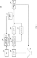
- FIG. 1 illustrates a configuration of an oil pressure control apparatus of the present disclosure
- FIG. 2 is a flowchart for explaining processing by the oil pressure control apparatus of the present disclosure.
- FIG. 3 shows an example of a lookup table for target oil pressures used in the oil pressure control apparatus of the present disclosure.
- FIG. 1 illustrates a configuration of oil pressure control apparatus 100 of the present disclosure.
- An engine oil flow in a hydraulic circuit and an electrical signal flow in oil pressure control apparatus 100 are indicated by respective different types of arrows in FIG. 1 .
- FIG. 1 illustrates that engine oil is sucked from oil pan 110 through an oil strainer (not illustrated) to oil pump 120 .
- the engine oil coming out of oil pump 120 is sent under pressure to electrically controlled oil-cooler bypassing valve 130 .
- electrically controlled oil-cooler bypassing valve 130 When electrically controlled oil-cooler bypassing valve 130 is open, the engine oil is sent under pressure to oil cooler 140 , and is then sent under pressure to cylinder block oil gallery 170 after cooled by oil cooler 140 .
- electrically controlled oil-cooler bypassing valve 130 When electrically controlled oil-cooler bypassing valve 130 is closed, the engine oil is sent under pressure to bypass oilway 150 , and is then sent under pressure to cylinder block oil gallery 170 without flowing through oil cooler 140 . In this case, the engine oil is not cooled by oil cooler 140 .
- the engine oil sent under pressure to cylinder block oil gallery 170 is supplied to a piston, cam head, main bearing, and connecting rod bearing (none of them are illustrated), which are engine members, and serves to lubricate these members. Part of the engine oil is supplied to the piston as an oil jet, and also serves to cool the piston. Then, the engine oil is returned to oil pan 110 .
- Oil pressure sensor 160 measures the oil pressure of the engine oil, and generates information indicating the oil pressure of the engine oil based on a measured result. Since oil pressure control apparatus 100 controls the oil pressure of the engine oil based on the result of measurement by oil pressure sensor 160 , it is preferable that oil pressure sensor 160 be disposed at a position in the hydraulic circuit where it is necessary to secure the oil pressure. By way of an example, oil pressure sensor 160 is disposed downstream of oil cooler 140 and bypass oilway 150 . Oil pressure sensor 160 is disposed in cylinder block oil gallery 170 , for example.
- Valve control section 220 is electrically connected to oil pressure sensor 160 , and obtains the information indicating the oil pressure of the engine oil from oil pressure sensor 160 . Further, valve control section 220 is electrically connected to ECU (engine control unit or electronic control unit) 210 , and obtains information indicating the engine speed and the fuel injection quantity of the engine from ECU 210 .
- ECU engine control unit or electronic control unit
- Valve control section 220 determines opening and closing of electrically controlled oil-cooler bypassing valve 130 based on the oil pressure of the engine oil.
- valve control section 220 determines a target oil pressure of the engine oil based on the engine speed and the fuel injection quantity, and determines the opening and closing of electrically controlled oil-cooler bypassing valve 130 based on a difference value between the target oil pressure and the measured oil pressure.
- valve control section 220 is provided with lookup table storage section 222 .
- Lookup table storage section 222 stores therein a lookup table specifying target oil pressures corresponding respectively to engine speeds and fuel injection quantities.
- valve control section 220 determines the target oil pressure of the engine oil corresponding to the engine speed and the fuel injection quantity using the information indicating the engine speed and the fuel injection quantity obtained from ECU 210 and using the lookup table read out from lookup table storage section 222 .
- the target oil pressure of the engine oil is determined using linear interpolation in a case of an engine speed and a fuel injection quantity which do not exist in the lookup table.
- FIG. 2 is a flowchart for explaining processing by oil pressure control apparatus 100 of the present disclosure.
- the processing of the flowchart illustrated in FIG. 2 is implemented, for example, by a program stored in a ROM (not illustrated) being read out and executed by a CPU (not illustrated) in oil pressure control apparatus 100 upon starting the engine of a vehicle.
- the processing of the flowchart illustrated in FIG. 2 is executed periodically (e.g., once per minute).
- valve control section 220 obtains the information indicating the engine speed from ECU 210 (step S 110 ). Next, valve control section 220 obtains the information indicating the fuel injection quantity from ECU 210 (step S 120 ).
- valve control section 220 determines the target oil pressure (step S 130 ). For example, valve control section 220 determines the target oil pressure of the engine oil corresponding to the engine speed and the fuel injection quantity using the information indicating the engine speed and the fuel injection quantity obtained from ECU 210 and using the lookup table read out from lookup table storage section 222 .
- FIG. 3 shows an example of the lookup table for the target oil pressures used in oil pressure control apparatus 100 of the present disclosure.
- the lookup table illustrated in FIG. 3 is a lookup table created by measuring oil pressures in a case of a normal oil flow and in a case of an oil temperature of 80 degrees Celsius and by recording the measured oil pressures for combinations of engine speeds and fuel injection quantities.
- valve control section 220 determines that the target oil pressure is 270 kPa.
- Oil pressure sensor 160 measures the oil pressure of the engine oil and generates the information indicating the measured oil pressure (step S 140 ). Then, valve control section 220 obtains the information indicating the measured oil pressure from oil pressure sensor 160 .
- valve control section 220 determines whether or not the difference value is greater than permissible error ⁇ (step S 160 ).
- permissible error ⁇ is a permissible error used when the measured oil pressure is adjusted to the target oil pressure.
- step S 160 When a determination result indicates that the difference value is greater than permissible error ⁇ (step S 160 : Yes), the processing proceeds to step S 170 .
- the processing proceeds to step S 170 in this case.
- Valve control section 220 opens electrically controlled oil-cooler bypassing valve 130 at step S 170 . Then, the processing proceeds to step S 140 .
- a predetermined wait time is elapsed before the processing proceeds to step S 140 .
- step S 160 when the difference value is not greater than permissible error E (step S 160 : No), the processing proceeds to step S 180 .
- valve control section 220 determines whether or not the difference value is smaller than ⁇ , which is a minus value of permissible error ⁇ .
- ⁇ which is a minus value of permissible error ⁇ .
- the processing proceeds to step S 190 .
- the difference value is ⁇ 20 kPa and is less than the minus value of permissible error E of ⁇ 13.5 kPa. Therefore, the processing proceeds to step S 190 in this case.
- Valve control section 220 closes electrically controlled oil-cooler bypassing valve 130 at step S 190 . Since the oil that circulates inside the engine flows through bypass oilway 150 that bypasses oil cooler 140 when electrically controlled oil-cooler bypassing valve 130 is closed, the oil is not cooled by oil cooler 140 . Then, the processing proceeds to step S 140 .
- a predetermined wait time is elapsed before the processing proceeds to step S 140 .
- step S 180 the processing is ended when the difference value is not less than ⁇ (step S 180 : No).
- oil pressure control apparatus 100 of the present disclosure the proper oil pressure of the engine oil depending on the engine speed and the fuel injection quantity can be secured. Accordingly, even when the hydraulic circuit malfunctions, damage to the engine can be mitigated and the durability reliability can be increased.
- the engine oil is not cooled and the oil pressure is not raised when the oil temperature is low. Therefore, there is a problem in that the oil pressure of the engine oil cannot be the proper oil pressure when the oil temperature is low. In contrast to this, the engine oil is cooled and the oil pressure is raised in the present disclosure even when the oil temperature is low. Therefore, the oil pressure of the engine oil can be the proper oil pressure even when the oil temperature is low.
- the oil temperature is not lowered when the proper oil pressure is already secured according to oil pressure control apparatus 100 of the present disclosure. Therefore, excellent fuel efficiency can be secured since it is possible to avoid an increase in friction between the engine members due to unnecessarily lowering the oil temperature.
- a temperature sensing section and a pressure sensing section disclosed in PTL 1 measure the pressure and the temperature of an oilway at the upstream side from an oil cooler (see FIGS. 2 and 3 ), and do not measure the pressure and the temperature of a main gallery.
- oil pressure sensor 160 is disposed, for example, in cylinder block oil gallery 170 in oil pressure control apparatus 100 of the present disclosure. Accordingly, it is possible to measure the oil pressure at a position where securing the oil pressure is needed more and to control such that the oil pressure is the proper oil pressure in oil pressure control apparatus 100 of the present disclosure.
- the target oil pressure of the engine oil corresponding to the engine speed and the fuel injection quantity is determined using the lookup table in the first embodiment.
- the target oil pressure may also be determined using a calculation formula based on the engine speed and the fuel injection quantity.
- ECU 210 and valve control section 220 are disposed as separate sections in the first embodiment. Alternatively, another embodiment in which ECU 210 and valve control section 220 are integrated is also possible.
- the engine oil that circulates inside the engine flows through oil cooler 140 when electrically controlled oil-cooler bypassing valve 130 is opened in the first embodiment. Meanwhile, the oil that circulates inside the engine flows through bypass oilway 150 that bypasses oil cooler 140 when electrically controlled oil-cooler bypassing valve 130 is closed. Alternatively, another embodiment in which the engine oil that circulates inside the engine flows through oil cooler 140 when electrically controlled oil-cooler bypassing valve 130 is closed is also possible. In this case, the engine oil that circulates inside the engine flows through bypass oilway 150 that bypasses oil cooler 140 , when electrically controlled oil-cooler bypassing valve 130 is opened.
- the state of electrically controlled oil-cooler bypassing valve 130 is changed between an opened state or a closed state in the first embodiment.
- another embodiment is also possible in which the extent of how much electrically controlled oil-cooler bypassing valve 130 is opened is adjusted depending on the magnitude of the difference value computed by subtracting the measured oil pressure from the target oil pressure. In this case, only part of the engine oil that circulates inside the engine is cooled by oil cooler 140 . This makes it possible to control the oil temperature and the oil pressure more smoothly.
- Permissible error ⁇ is a predetermined proportion (e.g., 5%) of the target oil pressure in the first embodiment.
- permissible error ⁇ is an error determined depending on the target oil pressure and the engine speed.
- the oil pressure control apparatus according to the present disclosure is suitable to be used in the vehicle in which an engine is mounted.
Landscapes
- Engineering & Computer Science (AREA)
- Mechanical Engineering (AREA)
- General Engineering & Computer Science (AREA)
- Chemical & Material Sciences (AREA)
- Combustion & Propulsion (AREA)
- Lubrication Of Internal Combustion Engines (AREA)
Abstract
Description
- 100 Oil pressure control apparatus
- 110 Oil pan
- 120 Oil pump
- 130 Electrically controlled oil-cooler bypassing valve
- 140 Oil cooler
- 150 Bypass oilway
- 160 Oil pressure sensor
- 170 Cylinder block oil gallery
- 210 ECU
- 220 Valve control section
- 222 Lookup table storage section
Claims (5)
Applications Claiming Priority (3)
| Application Number | Priority Date | Filing Date | Title |
|---|---|---|---|
| JP2016-229138 | 2016-11-25 | ||
| JP2016229138A JP6750476B2 (en) | 2016-11-25 | 2016-11-25 | Hydraulic control device |
| PCT/JP2017/041915 WO2018097151A1 (en) | 2016-11-25 | 2017-11-22 | Oil pressure control device |
Publications (2)
| Publication Number | Publication Date |
|---|---|
| US20190390579A1 US20190390579A1 (en) | 2019-12-26 |
| US10858972B2 true US10858972B2 (en) | 2020-12-08 |
Family
ID=62195582
Family Applications (1)
| Application Number | Title | Priority Date | Filing Date |
|---|---|---|---|
| US16/463,918 Active US10858972B2 (en) | 2016-11-25 | 2017-11-22 | Oil pressure control device |
Country Status (5)
| Country | Link |
|---|---|
| US (1) | US10858972B2 (en) |
| EP (1) | EP3546710B1 (en) |
| JP (1) | JP6750476B2 (en) |
| CN (1) | CN109952417B (en) |
| WO (1) | WO2018097151A1 (en) |
Citations (19)
| Publication number | Priority date | Publication date | Assignee | Title |
|---|---|---|---|---|
| JPS5928613U (en) | 1982-08-14 | 1984-02-22 | 三菱自動車工業株式会社 | Oil cooler bypass device |
| JPS59167904U (en) | 1983-04-26 | 1984-11-10 | 日野自動車株式会社 | Oil cooler inflow oil control device |
| US5339776A (en) | 1993-08-30 | 1994-08-23 | Chrysler Corporation | Lubrication system with an oil bypass valve |
| JPH10288022A (en) | 1997-04-11 | 1998-10-27 | Mitsubishi Motors Corp | Lubricating device for engine |
| JP2004003480A (en) | 2002-05-15 | 2004-01-08 | Dana Automotive Ltd | Lubrication system for engine and its operating method, lubricant removing method, change over valve, and lubricant sump |
| JP2010203263A (en) | 2009-02-27 | 2010-09-16 | Toyota Motor Corp | Control device of internal combustion engine |
| JP2010216411A (en) | 2009-03-18 | 2010-09-30 | Mazda Motor Corp | Engine cooling device |
| JP2013007306A (en) | 2011-06-23 | 2013-01-10 | Nippon Soken Inc | Engine oil cooling device |
| US8375917B1 (en) * | 2009-07-23 | 2013-02-19 | Gene Neal | Engine oil cooler |
| US20130151113A1 (en) * | 2011-12-13 | 2013-06-13 | Kia Motors Corporation | Oil pump control system for vehicle |
| JP2014015898A (en) | 2012-07-09 | 2014-01-30 | Isuzu Motors Ltd | Internal combustion engine and method for controlling internal combustion engine |
| WO2014073444A1 (en) | 2012-11-07 | 2014-05-15 | 日産自動車株式会社 | Oil supply device for internal combustion engine |
| US20140317923A1 (en) * | 2012-03-12 | 2014-10-30 | Kennieth Neal | Oil system for diesel engines that operate in cold environments |
| US8939132B2 (en) * | 2011-10-17 | 2015-01-27 | Mitsubishi Electric Corporation | Ignition control apparatus |
| US20170248065A1 (en) * | 2014-08-19 | 2017-08-31 | Borgwarner Inc. | Thermal management system and method ofmaking and using the same |
| US20170268587A1 (en) * | 2016-03-18 | 2017-09-21 | Honda Motor Co., Ltd. | Hydraulic system |
| US20180230870A1 (en) * | 2017-02-10 | 2018-08-16 | GM Global Technology Operations LLC | Engine oil pump with electronic oil pressure control |
| US20180274406A1 (en) * | 2015-01-26 | 2018-09-27 | Modine Manufacturing Company | Thermal Management Unit for Vehicle Powertrain |
| US20180274564A1 (en) * | 2015-09-29 | 2018-09-27 | Cnh Industrial America Llc | Hydraulic circuit for use on cvt vehicle |
Family Cites Families (4)
| Publication number | Priority date | Publication date | Assignee | Title |
|---|---|---|---|---|
| JPS5928613A (en) | 1982-08-09 | 1984-02-15 | Kobe Steel Ltd | Measuring device for wall thickness using oblique angle type two-probe method |
| MX2007006337A (en) * | 2004-11-30 | 2008-01-22 | Ap Moeller Maersk As | Method and system for reducing fuel consumption in a diesel engine. |
| JP2012145021A (en) * | 2011-01-11 | 2012-08-02 | Mitsubishi Heavy Ind Ltd | Cooling device for engine |
| EP2818652B1 (en) * | 2013-06-27 | 2016-04-27 | Volvo Car Corporation | lubrication system for combustion engine |
-
2016
- 2016-11-25 JP JP2016229138A patent/JP6750476B2/en active Active
-
2017
- 2017-11-22 WO PCT/JP2017/041915 patent/WO2018097151A1/en unknown
- 2017-11-22 US US16/463,918 patent/US10858972B2/en active Active
- 2017-11-22 CN CN201780070655.8A patent/CN109952417B/en active Active
- 2017-11-22 EP EP17873738.3A patent/EP3546710B1/en active Active
Patent Citations (20)
| Publication number | Priority date | Publication date | Assignee | Title |
|---|---|---|---|---|
| JPS5928613U (en) | 1982-08-14 | 1984-02-22 | 三菱自動車工業株式会社 | Oil cooler bypass device |
| JPS59167904U (en) | 1983-04-26 | 1984-11-10 | 日野自動車株式会社 | Oil cooler inflow oil control device |
| US5339776A (en) | 1993-08-30 | 1994-08-23 | Chrysler Corporation | Lubrication system with an oil bypass valve |
| JPH10288022A (en) | 1997-04-11 | 1998-10-27 | Mitsubishi Motors Corp | Lubricating device for engine |
| JP2004003480A (en) | 2002-05-15 | 2004-01-08 | Dana Automotive Ltd | Lubrication system for engine and its operating method, lubricant removing method, change over valve, and lubricant sump |
| US20040031463A1 (en) | 2002-05-15 | 2004-02-19 | Williams David John | Engine lubrication system |
| JP2010203263A (en) | 2009-02-27 | 2010-09-16 | Toyota Motor Corp | Control device of internal combustion engine |
| JP2010216411A (en) | 2009-03-18 | 2010-09-30 | Mazda Motor Corp | Engine cooling device |
| US8375917B1 (en) * | 2009-07-23 | 2013-02-19 | Gene Neal | Engine oil cooler |
| JP2013007306A (en) | 2011-06-23 | 2013-01-10 | Nippon Soken Inc | Engine oil cooling device |
| US8939132B2 (en) * | 2011-10-17 | 2015-01-27 | Mitsubishi Electric Corporation | Ignition control apparatus |
| US20130151113A1 (en) * | 2011-12-13 | 2013-06-13 | Kia Motors Corporation | Oil pump control system for vehicle |
| US20140317923A1 (en) * | 2012-03-12 | 2014-10-30 | Kennieth Neal | Oil system for diesel engines that operate in cold environments |
| JP2014015898A (en) | 2012-07-09 | 2014-01-30 | Isuzu Motors Ltd | Internal combustion engine and method for controlling internal combustion engine |
| WO2014073444A1 (en) | 2012-11-07 | 2014-05-15 | 日産自動車株式会社 | Oil supply device for internal combustion engine |
| US20170248065A1 (en) * | 2014-08-19 | 2017-08-31 | Borgwarner Inc. | Thermal management system and method ofmaking and using the same |
| US20180274406A1 (en) * | 2015-01-26 | 2018-09-27 | Modine Manufacturing Company | Thermal Management Unit for Vehicle Powertrain |
| US20180274564A1 (en) * | 2015-09-29 | 2018-09-27 | Cnh Industrial America Llc | Hydraulic circuit for use on cvt vehicle |
| US20170268587A1 (en) * | 2016-03-18 | 2017-09-21 | Honda Motor Co., Ltd. | Hydraulic system |
| US20180230870A1 (en) * | 2017-02-10 | 2018-08-16 | GM Global Technology Operations LLC | Engine oil pump with electronic oil pressure control |
Non-Patent Citations (2)
| Title |
|---|
| Extended EP Search Report from EP Application No. 17873738.3 dated Oct. 31, 2019, 8 pages. |
| International Search Report from International Application No. PCT/JP2017/041915 dated Dec. 26, 2017. |
Also Published As
| Publication number | Publication date |
|---|---|
| CN109952417B (en) | 2021-03-30 |
| EP3546710A4 (en) | 2019-12-04 |
| JP2018084217A (en) | 2018-05-31 |
| CN109952417A (en) | 2019-06-28 |
| EP3546710B1 (en) | 2023-03-29 |
| JP6750476B2 (en) | 2020-09-02 |
| EP3546710A1 (en) | 2019-10-02 |
| US20190390579A1 (en) | 2019-12-26 |
| WO2018097151A1 (en) | 2018-05-31 |
Similar Documents
| Publication | Publication Date | Title |
|---|---|---|
| CN105804829B (en) | Filter diagnostics and prediction | |
| US9175595B2 (en) | Engine with engine oil viscosity control and method for controlling the same | |
| US10400641B2 (en) | Fluid supply system | |
| EP1936135A1 (en) | Hydraulic control device for engine | |
| US20130206083A1 (en) | Engine with electronically controlled piston cooling jets and method for controlling the same | |
| KR101459891B1 (en) | Method for diagnosing failure of thermostat | |
| US20170074131A1 (en) | Method For Operating An Oil Circuit, In Particular For A Vehicle | |
| GB2484748A (en) | Oil Supply Control for Internal Combustion Engine Pistons | |
| US10858972B2 (en) | Oil pressure control device | |
| US20150330273A1 (en) | Method and apparatus for diagnosing bypass valve on oil cooling circuit for vehicles | |
| KR20140137671A (en) | Lubricating oil supplying apparatus of enging for ship | |
| US10487707B2 (en) | Fluid supply system | |
| JP2009191634A (en) | Lubricating device for internal combustion engine | |
| JP2006291758A (en) | Lubricating device and engine | |
| JP2009197664A (en) | Cooling device for engine | |
| JP4983560B2 (en) | Engine cooling system | |
| US20150204231A1 (en) | System for pressurizing a cooling circuit of an internal combustion engine equipped with a turbocompressor unit | |
| JP2010138817A (en) | Engine oil circulation system | |
| US10309276B2 (en) | On-engine fluid monitoring system | |
| CN109804153A (en) | Method and additional controller for internal combustion engine cold start-up optimization | |
| EP2863031B1 (en) | Engine with a viscosity measurement device | |
| JP2017082614A (en) | Oil pump oil passage system | |
| CN107587912B (en) | Method and system for diagnosing working state of oil cooler | |
| IT201600112687A1 (en) | Method of controlling the supply of oil to an internal combustion engine | |
| JP2015232309A (en) | Cylinder block lower part temperature estimation device |
Legal Events
| Date | Code | Title | Description |
|---|---|---|---|
| AS | Assignment |
Owner name: ISUZU MOTORS LIMITED, JAPAN Free format text: ASSIGNMENT OF ASSIGNORS INTEREST;ASSIGNORS:MURATA, YUUICHI;SUZUKI, KEN;HASHIMOTO, KOUJI;REEL/FRAME:049276/0113 Effective date: 20190522 |
|
| FEPP | Fee payment procedure |
Free format text: ENTITY STATUS SET TO UNDISCOUNTED (ORIGINAL EVENT CODE: BIG.); ENTITY STATUS OF PATENT OWNER: LARGE ENTITY |
|
| STPP | Information on status: patent application and granting procedure in general |
Free format text: DOCKETED NEW CASE - READY FOR EXAMINATION |
|
| STPP | Information on status: patent application and granting procedure in general |
Free format text: NON FINAL ACTION MAILED |
|
| STPP | Information on status: patent application and granting procedure in general |
Free format text: RESPONSE TO NON-FINAL OFFICE ACTION ENTERED AND FORWARDED TO EXAMINER |
|
| STPP | Information on status: patent application and granting procedure in general |
Free format text: NOTICE OF ALLOWANCE MAILED -- APPLICATION RECEIVED IN OFFICE OF PUBLICATIONS |
|
| STPP | Information on status: patent application and granting procedure in general |
Free format text: PUBLICATIONS -- ISSUE FEE PAYMENT VERIFIED |
|
| STCF | Information on status: patent grant |
Free format text: PATENTED CASE |
|
| MAFP | Maintenance fee payment |
Free format text: PAYMENT OF MAINTENANCE FEE, 4TH YEAR, LARGE ENTITY (ORIGINAL EVENT CODE: M1551); ENTITY STATUS OF PATENT OWNER: LARGE ENTITY Year of fee payment: 4 |