US10858866B2 - Housing for a latch with water drain opening and method of draining water from a latch - Google Patents
Housing for a latch with water drain opening and method of draining water from a latch Download PDFInfo
- Publication number
- US10858866B2 US10858866B2 US15/165,354 US201615165354A US10858866B2 US 10858866 B2 US10858866 B2 US 10858866B2 US 201615165354 A US201615165354 A US 201615165354A US 10858866 B2 US10858866 B2 US 10858866B2
- Authority
- US
- United States
- Prior art keywords
- housing
- latch
- interior
- fluid pathway
- wall member
- Prior art date
- Legal status (The legal status is an assumption and is not a legal conclusion. Google has not performed a legal analysis and makes no representation as to the accuracy of the status listed.)
- Expired - Fee Related, expires
Links
Images


Classifications
-
- E—FIXED CONSTRUCTIONS
- E05—LOCKS; KEYS; WINDOW OR DOOR FITTINGS; SAFES
- E05B—LOCKS; ACCESSORIES THEREFOR; HANDCUFFS
- E05B85/00—Details of vehicle locks not provided for in groups E05B77/00 - E05B83/00
- E05B85/02—Lock casings
-
- E—FIXED CONSTRUCTIONS
- E05—LOCKS; KEYS; WINDOW OR DOOR FITTINGS; SAFES
- E05B—LOCKS; ACCESSORIES THEREFOR; HANDCUFFS
- E05B77/00—Vehicle locks characterised by special functions or purposes
- E05B77/34—Protection against weather or dirt, e.g. against water ingress
-
- E—FIXED CONSTRUCTIONS
- E05—LOCKS; KEYS; WINDOW OR DOOR FITTINGS; SAFES
- E05B—LOCKS; ACCESSORIES THEREFOR; HANDCUFFS
- E05B77/00—Vehicle locks characterised by special functions or purposes
- E05B77/44—Burglar prevention, e.g. protecting against opening by unauthorised tools
Definitions
- the door latch assembly includes an actuator having a motor for manipulating the state of the latch between locked and unlocked and/or opened and closed.
- electrical components may also be provided that generate signals indicative of the state of the latch. These signals may be provided by sensors or switches that are typically exposed to various environmental conditions and the historical performance of such systems have exhibited a distinct need to function flawlessly in wet environments.
- the latch and its associated actuator can be sealed from the environment. However, this adds cost and complexity to the latch assembly.
- some door latch actuators may be designed to be fully sealed units to prevent water ingress, which is very difficult to achieve practically and cost effectively.
- the plastic actuator cases are either laser welded (or ultrasonic welded) or screwed/clipped together with a seal gasket between the mating halves of the cases. These sealing methods require high levels of accuracy especially for the molded components and expensive manufacturing methods and controls.
- a drain opening is provided in the latch housing by providing an opening or window into the interior of the housing, the opening or window may not provide a suitable path for egress of fluids from the housing.
- a housing for a vehicle latch having a fluid pathway extending from an interior of the housing to an exterior of the housing through a perimeter wall, wherein the fluid pathway is defined by an inclined surface that extends downwardly and away from an interior of the housing to an exterior of the housing.
- a vehicle latch having: a housing; a fluid pathway extending from an interior of the housing to an exterior of the housing through a perimeter wall of the housing, wherein the fluid pathway is defined by an inclined surface that extends downwardly and away from an interior of the housing to an exterior of the housing when the latch is in an installed configuration.
- a method of draining fluids from an interior of a vehicle latch including the steps of: locating a fluid pathway in a housing of the vehicle latch, wherein the fluid pathway extends from an interior of the housing to an exterior of the housing through a perimeter wall of the housing, wherein the fluid pathway is defined by an inclined surface that extends downwardly and away from an interior of the housing to an exterior of the housing when the latch is in an installed configuration.
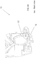
- FIG. 1 is a perspective front view of a latch assembly without a drain opening in accordance with an embodiment of the present invention
- FIG. 2 is a perspective front view of the latch assembly of FIG. 1 with a portion of the latch assembly removed;
- FIG. 3 is a perspective front view of the housing of the latch assembly illustrating a drain opening in accordance with an embodiment of the present invention
- FIG. 4A is an enlarged front perspective view of a housing without a drain opening in accordance with an embodiment of the present invention.
- FIG. 4B is an enlarged front perspective view of a housing with a drain opening in accordance with an embodiment of the present invention.
- FIG. 5A is a back view of the housing of FIGS. 1 and 2 without a drain opening in accordance with an embodiment of the present invention
- FIG. 5B is a back view of the housing of FIGS. 1 and 2 with a drain opening in accordance with an embodiment of the present invention
- FIG. 6A is an enlarged rear view of a housing without a drain opening in accordance with an embodiment of the present invention.
- FIG. 6B is an enlarged rear view of a housing with a drain opening in accordance with an embodiment of the present invention.
- FIG. 7A is a rear perspective view of a housing without a drain opening in accordance with an embodiment of the present invention.
- FIG. 7B is a rear perspective view of a housing with a drain opening in accordance with an embodiment of the present invention.
- FIG. 8A is a cross sectional rear perspective view of a housing without a drain opening in accordance with an embodiment of the present invention.
- FIG. 8B is a cross sectional rear perspective view of a housing with a drain opening in accordance with an embodiment of the present invention.
- FIG. 9A is a cross sectional front perspective view of a housing without a drain opening in accordance with an embodiment of the present invention.
- FIG. 9B is a cross sectional front perspective view of a housing with a drain opening in accordance with an embodiment of the present invention.
- FIG. 10 is a perspective view of the latch housing with a drain opening in accordance with an embodiment of the present invention
- FIG. 11 is a cross sectional perspective view of a housing with a drain opening in accordance with an embodiment of the present invention.
- FIG. 12 is a perspective view of the latch housing without a drain opening in accordance with an embodiment of the present invention.
- a latch housing is configured to have a water drain or fluid passageway extending therethrough that will enable the latch assembly to shed water and drain it away from critical areas within the latch or latch assembly, rather than attempt to design them to be completely sealed units.
- latch or latch assembly 10 may be contemplated for use with a vehicle door latch.
- the housing 10 is applicable to any environment where the features of various embodiments of the invention are desired.
- the latch assembly or latch can be attached to a vehicle structure such that the fork bolt is moved between the open position and the closed position when a hood, door, window, lift gate, etc. is opened and closed and the fork bolt engages a striker that is attached to the hood, door, window, lift gate, etc.
- the latch or latch assembly 10 may be secured to the hood, door, window, lift gate, etc. and the striker is secured to the vehicle body at an opening into which the hood, door, window, lift gate, etc. is received.
- the latch or latch assembly 10 may be located on a first element or first vehicle component which is either a frame (e.g., body member surrounding or proximate to an opening the movable member covers) or a movable member (e.g., door, window, lift gate, hood, etc.) of the vehicle.
- a frame e.g., body member surrounding or proximate to an opening the movable member covers
- a movable member e.g., door, window, lift gate, hood, etc.
- FIGS. 1, 2, 4A, 5A, 6A, 7A, 8A, 9A and 12 illustrate a latch or latch assembly or portions thereof without a drain opening in accordance with an exemplary embodiment of the present invention
- FIGS. 3, 4B, 5B, 6B, 7B, 8B, 9B, 10 and 11 illustrate a latch or latch assembly or portions thereof with a drain opening in accordance with an exemplary embodiment of the present invention.
- the latch or latch assembly has a housing or latch housing 12 that has a liquid fluid pathway or water pathway 14 extending from an interior 16 of the housing 12 to an exterior 18 of the housing 12 .
- the opening, or fluid pathway or liquid pathway 14 extends through a perimeter wall 20 , wherein the fluid pathway is formed such that water or fluid flow from the interior 16 of the housing 12 to the exterior 18 is allowed or unimpeded in a first direction represented by arrows 22 .
- the perimeter wall 20 may be located proximate to the outer periphery of the housing 12 .
- the housing 12 of the latch or latch assembly 10 is formed from an easily moldable material such as plastic.
- the opening or fluid pathway 14 has an inclined or downwardly sloping surface 24 so that gravity can pull fluids from the interior 16 of the latch or latch assembly 10 towards the exterior 18 of the latch or latch assembly 10 .
- the configurations illustrated in the attached FIGS. represent the installed configuration of the latch or latch assembly 10 so that water and fluids will be drawn from the interior 16 of the latch or latch assembly 10 to the exterior 18 of the latch or latch assembly 10 .
- the drain path and/or sloping surface 24 are designed in such a way to prevent against direct air flow into the housing and, therefore, avoid dust intrusion into latch assembly 10 .
- the opening 14 of the latch or latch assembly 10 also includes a wall member 26 that extends from the inclined surface and is positioned in order to prevent unauthorized access into the interior 16 of the latch or latch assembly 10 in an attempt to manipulate the latch or latch assembly 10 with a tool or other device capable of being inserted into the latch or latch assembly 10 .
- the wall member 26 which is functionally considered a guard wall member, is configured to prevent unauthorized operation of the latch or latch assembly 10 while still allowing fluids to drain from the interior 18 of the latch or latch assembly 10 to the exterior of the latch or latch assembly 10 .
- the inclined or ramped surface 24 prevents accumulation of fluids in the interior of the housing 12 , which may freeze if the temperatures the latch or latch assembly 10 is exposed to is less than the freezing point of the accumulated fluids.
- frozen fluids or ice is illustrated as item 27 in FIG. 12 . If the fluids freeze they may interfere or prohibit operational movement of movably component(s) 28 of the latch or latch assembly 10 .
- the movable component 28 is a release lever of the latch 10 .
- other movable components of latch 10 are considered to be within the scope of various embodiments of the present invention.
- the inclined or ramped surface 24 into the housing 12 of the latch or latch assembly 10 fluids are able to be drawn by gravity from the interior 16 of the latch or latch assembly 10 to the exterior 18 of the latch or latch assembly 10 .
- one of the intended benefits is to prevent the accumulation of fluids that may freeze within the interior 16 of the housing of the latch or latch assembly 10 .
- Prior latch housing designs do not allow water to flow out of the latch assembly, causing water to accumulate in the bottom of housing and freeze when exposed to cold environments (temperatures below water freezing point); ice formation may not allow proper function of a release lever or other components of the latch, which will prevent the door latch from being able to open via inside and outside release handles.
- Various embodiments of the present invention provide a new feature that includes a water drain hole with an angled bottom wall that avoids water accumulation, and still protects the latch assembly against theft (antitheft feature) by two walls ( 30 and 32 ) that prevent an external object from being introduced to the latch to get it to open (unlatch).
- drain path is designed in such a way to prevent against direct air flow and, therefore, avoid dust intrusion into latch assembly.
- the terms “first,” “second,” and the like, herein do not denote any order, quantity, or importance, but rather are used to distinguish one element from another, and the terms “a” and “an” herein do not denote a limitation of quantity, but rather denote the presence of at least one of the referenced item.
- the terms “bottom” and “top” are used herein, unless otherwise noted, merely for convenience of description, and are not limited to any one position or spatial orientation.
Landscapes
- Lock And Its Accessories (AREA)
Abstract
Description
Claims (20)
Priority Applications (1)
| Application Number | Priority Date | Filing Date | Title |
|---|---|---|---|
| US15/165,354 US10858866B2 (en) | 2015-05-26 | 2016-05-26 | Housing for a latch with water drain opening and method of draining water from a latch |
Applications Claiming Priority (2)
| Application Number | Priority Date | Filing Date | Title |
|---|---|---|---|
| US201562166425P | 2015-05-26 | 2015-05-26 | |
| US15/165,354 US10858866B2 (en) | 2015-05-26 | 2016-05-26 | Housing for a latch with water drain opening and method of draining water from a latch |
Publications (2)
| Publication Number | Publication Date |
|---|---|
| US20160348407A1 US20160348407A1 (en) | 2016-12-01 |
| US10858866B2 true US10858866B2 (en) | 2020-12-08 |
Family
ID=57281806
Family Applications (1)
| Application Number | Title | Priority Date | Filing Date |
|---|---|---|---|
| US15/165,354 Expired - Fee Related US10858866B2 (en) | 2015-05-26 | 2016-05-26 | Housing for a latch with water drain opening and method of draining water from a latch |
Country Status (3)
| Country | Link |
|---|---|
| US (1) | US10858866B2 (en) |
| CN (2) | CN205778044U (en) |
| DE (1) | DE102016109556A1 (en) |
Cited By (4)
| Publication number | Priority date | Publication date | Assignee | Title |
|---|---|---|---|---|
| FR3123674A1 (en) * | 2021-06-07 | 2022-12-09 | Psa Automobiles Sa | Improved lock cover for motor vehicle doors |
| USD1057636S1 (en) * | 2022-07-22 | 2025-01-14 | Inteva Products, Llc | Vehicle latch |
| USD1057635S1 (en) * | 2022-06-13 | 2025-01-14 | Inteva Products, Llc | Vehicle latch |
| USD1082491S1 (en) | 2022-07-22 | 2025-07-08 | Inteva Products, Llc | Vehicle latch |
Families Citing this family (2)
| Publication number | Priority date | Publication date | Assignee | Title |
|---|---|---|---|---|
| DE102016109556A1 (en) | 2015-05-26 | 2016-12-01 | Inteva Products, Llc | Housing for a lock with water drainage opening and method for draining water from a lock |
| JP6762242B2 (en) * | 2017-01-30 | 2020-09-30 | ジーコム コーポレイションGecom Corporation | Vehicle door latch device |
Citations (18)
| Publication number | Priority date | Publication date | Assignee | Title |
|---|---|---|---|---|
| US3969789A (en) | 1975-05-27 | 1976-07-20 | General Motors Corporation | Door hold-open mechanism |
| US5169186A (en) * | 1988-07-21 | 1992-12-08 | Aisin Seiki Kabushiki Kaisha | Door lock device |
| US5678869A (en) * | 1995-06-01 | 1997-10-21 | Mitsui Kinzoku Kogyo Kabushiki Kaisha | Switch for detecting full-latch condition in vehicle door latch device |
| US6375234B1 (en) * | 1999-05-04 | 2002-04-23 | Kiekert Ag | Motor-vehicle door latch with sealed housing |
| US6568741B1 (en) | 2002-06-26 | 2003-05-27 | General Motors Corporation | Door hinge for vehicle |
| US6679531B2 (en) | 2001-05-03 | 2004-01-20 | Delphi Technologies, Inc. | Vehicle compartment latch |
| US20040262927A1 (en) * | 2003-01-30 | 2004-12-30 | Aisin Seiki Kabushiki Kaisha | Door lock device |
| US20050140148A1 (en) * | 2003-12-10 | 2005-06-30 | Frank Stoof | Vehicle latch with partially decoupled key cylinder lever |
| US7637542B2 (en) | 2005-02-23 | 2009-12-29 | Aisin Seiki Kabushiki Kaisha | Door lock apparatus |
| US20100127512A1 (en) | 2008-11-26 | 2010-05-27 | Inteva Products Llp | Vehicle door latch |
| US20110204659A1 (en) | 2010-02-18 | 2011-08-25 | Eduardo Estrada | Vehicle door latch |
| US20120292927A1 (en) | 2011-05-19 | 2012-11-22 | Francisco Javier Vazquez | Vehicle latch |
| US8348310B2 (en) | 2009-08-06 | 2013-01-08 | Inteva Products, Llc | Hold open lever integrated to latch housing |
| CN202997173U (en) | 2012-12-14 | 2013-06-12 | 胡连精密股份有限公司 | Electrical connector with drainage function |
| CN203499347U (en) | 2013-08-08 | 2014-03-26 | 上海威士迪电子技术有限公司 | Water-proof device of electronic lock shell |
| CN104347296A (en) | 2013-08-06 | 2015-02-11 | 上海海拉电子有限公司 | Automobile starting switch |
| DE102014102538A1 (en) | 2013-11-22 | 2015-05-28 | Inteva Products, Llc | Housing for a lock with a drainage labyrinth |
| US20160348407A1 (en) | 2015-05-26 | 2016-12-01 | Inteva Products, Llc | Housing for a latch with water drain opening and method of draining water from a latch |
Family Cites Families (1)
| Publication number | Priority date | Publication date | Assignee | Title |
|---|---|---|---|---|
| US10000949B2 (en) | 2013-03-29 | 2018-06-19 | Inteva Products, Llc | Apparatus and method for preventing undesired engagement of hold open lever in a latch |
-
2016
- 2016-05-24 DE DE102016109556.7A patent/DE102016109556A1/en not_active Ceased
- 2016-05-25 CN CN201620485499.4U patent/CN205778044U/en not_active Withdrawn - After Issue
- 2016-05-25 CN CN201610353036.7A patent/CN106193846B/en not_active Expired - Fee Related
- 2016-05-26 US US15/165,354 patent/US10858866B2/en not_active Expired - Fee Related
Patent Citations (20)
| Publication number | Priority date | Publication date | Assignee | Title |
|---|---|---|---|---|
| US3969789A (en) | 1975-05-27 | 1976-07-20 | General Motors Corporation | Door hold-open mechanism |
| US5169186A (en) * | 1988-07-21 | 1992-12-08 | Aisin Seiki Kabushiki Kaisha | Door lock device |
| US5678869A (en) * | 1995-06-01 | 1997-10-21 | Mitsui Kinzoku Kogyo Kabushiki Kaisha | Switch for detecting full-latch condition in vehicle door latch device |
| US6375234B1 (en) * | 1999-05-04 | 2002-04-23 | Kiekert Ag | Motor-vehicle door latch with sealed housing |
| US6679531B2 (en) | 2001-05-03 | 2004-01-20 | Delphi Technologies, Inc. | Vehicle compartment latch |
| US6568741B1 (en) | 2002-06-26 | 2003-05-27 | General Motors Corporation | Door hinge for vehicle |
| US20040262927A1 (en) * | 2003-01-30 | 2004-12-30 | Aisin Seiki Kabushiki Kaisha | Door lock device |
| US20050140148A1 (en) * | 2003-12-10 | 2005-06-30 | Frank Stoof | Vehicle latch with partially decoupled key cylinder lever |
| US7637542B2 (en) | 2005-02-23 | 2009-12-29 | Aisin Seiki Kabushiki Kaisha | Door lock apparatus |
| CN102199962A (en) | 2005-02-23 | 2011-09-28 | 爱信精机株式会社 | Door lock apparatus |
| US20100127512A1 (en) | 2008-11-26 | 2010-05-27 | Inteva Products Llp | Vehicle door latch |
| US8348310B2 (en) | 2009-08-06 | 2013-01-08 | Inteva Products, Llc | Hold open lever integrated to latch housing |
| US20110204659A1 (en) | 2010-02-18 | 2011-08-25 | Eduardo Estrada | Vehicle door latch |
| US20120292927A1 (en) | 2011-05-19 | 2012-11-22 | Francisco Javier Vazquez | Vehicle latch |
| CN202997173U (en) | 2012-12-14 | 2013-06-12 | 胡连精密股份有限公司 | Electrical connector with drainage function |
| CN104347296A (en) | 2013-08-06 | 2015-02-11 | 上海海拉电子有限公司 | Automobile starting switch |
| CN203499347U (en) | 2013-08-08 | 2014-03-26 | 上海威士迪电子技术有限公司 | Water-proof device of electronic lock shell |
| DE102014102538A1 (en) | 2013-11-22 | 2015-05-28 | Inteva Products, Llc | Housing for a lock with a drainage labyrinth |
| US20160348407A1 (en) | 2015-05-26 | 2016-12-01 | Inteva Products, Llc | Housing for a latch with water drain opening and method of draining water from a latch |
| CN205778044U (en) | 2015-05-26 | 2016-12-07 | 因特瓦产品有限责任公司 | There is the lock bolt housing of discharge outlet |
Non-Patent Citations (16)
| Title |
|---|
| CN Office Action for Application No. 201610353036.7. |
| CN Office Action for Application No. 201610353036.7; dated Aug. 17, 2020. |
| CN Office Action for Application No. 201610353036.7; dated Jan. 2, 2019. |
| CN Office Action for Application No. 201610353036.7; dated Jul. 12, 2019. |
| Decision on Rejection for Application 201610353036.7; dated Jan. 21, 2020. |
| English Machine Translation to Abstract CN104347296. |
| English Machine Translation to Abstract CN202997173. |
| English Machine Translation to Abstract CN203499347. |
| English Machine Translation to Abstract DE102014102538. |
| English Translation of Decision on Rejection for Application 201610353036.7; dated Jan. 21, 2020. |
| English Translation to CN Office Action for Application No. 201610353036.7. |
| English Translation to CN Office Action for Application No. 201610353036.7; dated Aug. 17, 2020. |
| English Translation to CN Office Action for Application No. 201610353036.7; dated Jan. 2, 2019. |
| English Translation to CN Office Action for Application No. 201610353036.7; dated Jul. 12, 2019. |
| Search Report for Application No. 201610353036.7. |
| Search Report for Application No. 201610353036.7; dated Aug. 7, 2020. |
Cited By (4)
| Publication number | Priority date | Publication date | Assignee | Title |
|---|---|---|---|---|
| FR3123674A1 (en) * | 2021-06-07 | 2022-12-09 | Psa Automobiles Sa | Improved lock cover for motor vehicle doors |
| USD1057635S1 (en) * | 2022-06-13 | 2025-01-14 | Inteva Products, Llc | Vehicle latch |
| USD1057636S1 (en) * | 2022-07-22 | 2025-01-14 | Inteva Products, Llc | Vehicle latch |
| USD1082491S1 (en) | 2022-07-22 | 2025-07-08 | Inteva Products, Llc | Vehicle latch |
Also Published As
| Publication number | Publication date |
|---|---|
| DE102016109556A1 (en) | 2016-12-01 |
| US20160348407A1 (en) | 2016-12-01 |
| CN106193846B (en) | 2021-01-15 |
| CN205778044U (en) | 2016-12-07 |
| CN106193846A (en) | 2016-12-07 |
Similar Documents
| Publication | Publication Date | Title |
|---|---|---|
| US10858866B2 (en) | Housing for a latch with water drain opening and method of draining water from a latch | |
| US8196974B2 (en) | Vehicle door latch assembly | |
| US20180216370A1 (en) | Vehicle door latch device | |
| JP5070649B2 (en) | Vehicle door latch device | |
| KR20190141182A (en) | Car lock | |
| CN105916715B (en) | Body construction with door sealing part | |
| CN102822434A (en) | Vehicle door lock device | |
| JP6716988B2 (en) | Vehicle door latch device | |
| US20190323271A1 (en) | Latch housing and method for isolating components in a latch housing | |
| US20190106913A1 (en) | Cable for vehicle door | |
| US6375234B1 (en) | Motor-vehicle door latch with sealed housing | |
| US8677692B2 (en) | Door latch cover | |
| US20150135782A1 (en) | Push button lock | |
| US20120043766A1 (en) | Hood latch with theft protection feature | |
| US11519205B2 (en) | Closure latch assembly with power lock mechanism having outside lock lever water protection | |
| GB2528747A (en) | Vehicle door latch device | |
| WO2017154733A1 (en) | Ultra-low temperature freezer | |
| US6471266B1 (en) | Door latch cover for automotive vehicle | |
| JP6183321B2 (en) | Vehicle filler lid structure | |
| JP6707002B2 (en) | Vehicle door latch device | |
| CN102606005A (en) | Door assembly with anti-theft device | |
| US20150292242A1 (en) | Enclosures with integrated locking system | |
| JP6346026B2 (en) | Vehicle door lock device | |
| WO2021098601A1 (en) | Latch assembly for door-in-door refrigeration appliance | |
| JP4396991B2 (en) | cabinet |
Legal Events
| Date | Code | Title | Description |
|---|---|---|---|
| AS | Assignment |
Owner name: INTEVA PRODUCTS, LLC, MICHIGAN Free format text: ASSIGNMENT OF ASSIGNORS INTEREST;ASSIGNORS:MADRID, JOSE MANUEL;GUEVARA, FRANCISCO JAVIER;ESCAMILLA, MANUEL;SIGNING DATES FROM 20160520 TO 20160523;REEL/FRAME:038728/0556 |
|
| AS | Assignment |
Owner name: DEUTSCHE BANK AG NEW YORK BRANCH, AS COLLATERAL AGENT, NEW YORK Free format text: SECURITY AGREEMENT;ASSIGNOR:INTEVA PRODUCTS, LLC;REEL/FRAME:039973/0305 Effective date: 20160908 Owner name: DEUTSCHE BANK AG NEW YORK BRANCH, AS COLLATERAL AG Free format text: SECURITY AGREEMENT;ASSIGNOR:INTEVA PRODUCTS, LLC;REEL/FRAME:039973/0305 Effective date: 20160908 |
|
| AS | Assignment |
Owner name: WELLS FARGO BANK, NATIONAL ASSOCIATION, NEW YORK Free format text: SECURITY AGREEMENT;ASSIGNOR:INTEVA PRODUCTS, LLC;REEL/FRAME:042857/0001 Effective date: 20160908 |
|
| AS | Assignment |
Owner name: INTEVA PRODUCTS, LLC, MICHIGAN Free format text: RELEASE BY SECURED PARTY;ASSIGNOR:DEUTSCHE BANK AG NEW YORK BRANCH;REEL/FRAME:043038/0246 Effective date: 20170627 |
|
| STPP | Information on status: patent application and granting procedure in general |
Free format text: RESPONSE TO NON-FINAL OFFICE ACTION ENTERED AND FORWARDED TO EXAMINER |
|
| STPP | Information on status: patent application and granting procedure in general |
Free format text: FINAL REJECTION MAILED |
|
| STCV | Information on status: appeal procedure |
Free format text: NOTICE OF APPEAL FILED |
|
| STCV | Information on status: appeal procedure |
Free format text: APPEAL BRIEF (OR SUPPLEMENTAL BRIEF) ENTERED AND FORWARDED TO EXAMINER |
|
| STPP | Information on status: patent application and granting procedure in general |
Free format text: NON FINAL ACTION MAILED |
|
| STPP | Information on status: patent application and granting procedure in general |
Free format text: RESPONSE TO NON-FINAL OFFICE ACTION ENTERED AND FORWARDED TO EXAMINER |
|
| STPP | Information on status: patent application and granting procedure in general |
Free format text: FINAL REJECTION MAILED |
|
| STPP | Information on status: patent application and granting procedure in general |
Free format text: RESPONSE AFTER FINAL ACTION FORWARDED TO EXAMINER |
|
| STPP | Information on status: patent application and granting procedure in general |
Free format text: NOTICE OF ALLOWANCE MAILED -- APPLICATION RECEIVED IN OFFICE OF PUBLICATIONS |
|
| STCF | Information on status: patent grant |
Free format text: PATENTED CASE |
|
| AS | Assignment |
Owner name: CERBERUS BUSINESS FINANCE, LLC, AS COLLATERAL AGENT, NEW YORK Free format text: PATENT SECURITY AGREEMENT;ASSIGNOR:INTEVA PRODUCTS, LLC;REEL/FRAME:059766/0348 Effective date: 20220322 |
|
| FEPP | Fee payment procedure |
Free format text: MAINTENANCE FEE REMINDER MAILED (ORIGINAL EVENT CODE: REM.); ENTITY STATUS OF PATENT OWNER: LARGE ENTITY |
|
| LAPS | Lapse for failure to pay maintenance fees |
Free format text: PATENT EXPIRED FOR FAILURE TO PAY MAINTENANCE FEES (ORIGINAL EVENT CODE: EXP.); ENTITY STATUS OF PATENT OWNER: LARGE ENTITY |
|
| STCH | Information on status: patent discontinuation |
Free format text: PATENT EXPIRED DUE TO NONPAYMENT OF MAINTENANCE FEES UNDER 37 CFR 1.362 |
|
| FP | Lapsed due to failure to pay maintenance fee |
Effective date: 20241208 |