US10857638B2 - Vise clamp - Google Patents
Vise clamp Download PDFInfo
- Publication number
- US10857638B2 US10857638B2 US15/678,873 US201715678873A US10857638B2 US 10857638 B2 US10857638 B2 US 10857638B2 US 201715678873 A US201715678873 A US 201715678873A US 10857638 B2 US10857638 B2 US 10857638B2
- Authority
- US
- United States
- Prior art keywords
- clamp
- vise
- nose
- face
- angled
- Prior art date
- Legal status (The legal status is an assumption and is not a legal conclusion. Google has not performed a legal analysis and makes no representation as to the accuracy of the status listed.)
- Expired - Fee Related, expires
Links
Images


Classifications
-
- B—PERFORMING OPERATIONS; TRANSPORTING
- B23—MACHINE TOOLS; METAL-WORKING NOT OTHERWISE PROVIDED FOR
- B23Q—DETAILS, COMPONENTS, OR ACCESSORIES FOR MACHINE TOOLS, e.g. ARRANGEMENTS FOR COPYING OR CONTROLLING; MACHINE TOOLS IN GENERAL CHARACTERISED BY THE CONSTRUCTION OF PARTICULAR DETAILS OR COMPONENTS; COMBINATIONS OR ASSOCIATIONS OF METAL-WORKING MACHINES, NOT DIRECTED TO A PARTICULAR RESULT
- B23Q3/00—Devices holding, supporting, or positioning work or tools, of a kind normally removable from the machine
- B23Q3/02—Devices holding, supporting, or positioning work or tools, of a kind normally removable from the machine for mounting on a work-table, tool-slide, or analogous part
- B23Q3/06—Work-clamping means
- B23Q3/069—Work-clamping means for pressing workpieces against a work-table
-
- B—PERFORMING OPERATIONS; TRANSPORTING
- B25—HAND TOOLS; PORTABLE POWER-DRIVEN TOOLS; MANIPULATORS
- B25B—TOOLS OR BENCH DEVICES NOT OTHERWISE PROVIDED FOR, FOR FASTENING, CONNECTING, DISENGAGING, OR HOLDING
- B25B5/00—Clamps
- B25B5/06—Arrangements for positively actuating jaws
- B25B5/10—Arrangements for positively actuating jaws using screws
- B25B5/104—Arrangements for positively actuating jaws using screws with one screw and one clamping lever and one fulcrum element
- B25B5/105—Arrangements for positively actuating jaws using screws with one screw and one clamping lever and one fulcrum element with one end of the lever resting on a table and the screw being positioned between the ends of the lever
-
- B—PERFORMING OPERATIONS; TRANSPORTING
- B25—HAND TOOLS; PORTABLE POWER-DRIVEN TOOLS; MANIPULATORS
- B25B—TOOLS OR BENCH DEVICES NOT OTHERWISE PROVIDED FOR, FOR FASTENING, CONNECTING, DISENGAGING, OR HOLDING
- B25B5/00—Clamps
- B25B5/06—Arrangements for positively actuating jaws
- B25B5/10—Arrangements for positively actuating jaws using screws
- B25B5/104—Arrangements for positively actuating jaws using screws with one screw and one clamping lever and one fulcrum element
- B25B5/106—Arrangements for positively actuating jaws using screws with one screw and one clamping lever and one fulcrum element with one end of the lever resting on an additional block and the screw being positioned between the ends of the lever
- B25B5/107—Blocks therefor
Definitions
- the present disclosure relates, in general, to clamps, and more particularly to clamping devices for use in precise machining situations utilizing slotted work tables such as would be found on metal milling or broaching machines.
- Prior art vise clamps are merely rectangular metal blocks having upper peripheral flanges and central orifices for the passage of a T nut and a bolt to secure the blocks to the slotted worktable.
- the problem herein lies when attempting to clamp a vise or work piece that has its own raised, top face peripheral edge. This does not provide a substantial gripping contact and under load may allow the vise or clamped work piece to move.
- the clamp's body is rectangular, when clamping angularly, it does not allow the clamp's upper peripheral flange to extend onto the vise or work piece a substantial distance because of the physical interference with the clamp's corners.
- the pressure per square inch is reduced which results in a minimized gripping or clamping ability.
- an improved vise clamp for use on a slotted work table that accommodates all styles of vises (with or without raised peripheral edges), can provide a substantial gripping surface, can get its body close or into contact with the vise/work piece, and has an enhanced gripping force, would fulfill a long felt need in the metal machining and fabrication industry.
- This new invention utilizes and combines known and new technologies in a unique and novel configuration to overcome the aforementioned problems and accomplish this.
- a clamp for use on a slotted work table that can abut the vise/work piece with one of its body's angled side faces is provided.
- a clamp with an extended nose for depth of contact onto the vise/work piece to ensure adequate gripping contact onto the appropriate surface.
- a clamp with a radiused linear groove formed thereon to accommodate clamping to a vise with a raise peripheral rib is provided.
- a clamp capable of generating increased clamping forces/friction on both the slotted table and the vise/work piece.
- a clamp in yet another aspect, has an elongated or elliptical central through bore to accommodate adjustable clamp placement with respect to the location of the work table slots
- FIG. 1 is an exploded perspective view of the vise clamp
- FIG. 2 is an assembled view of the vise clamp
- FIG. 3 is a side view of the assembled vise clamp
- FIG. 4 is a top view of the assembled vise clamp
- FIG. 5 is a back view of the assembled vise clamp
- FIG. 6 is a side perspective view of the vise clamp body
- FIG. 7 is a top view of the vise clamp body
- FIG. 8 is a left side view of the vise clamp body
- FIG. 9 is a back view of the vise clamp body
- FIG. 10 is a right side view of the vise clamp body
- FIG. 11 is a nose or front end view of the vise clamp body
- FIG. 12 is a bottom view of the vise clamp body
- FIG. 13 is a side perspective view of the T bolt
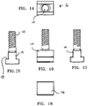
- FIG. 14 is a top view of the T bolt
- FIG. 15 is a back view of the T bolt
- FIG. 16 is a right side view of the T bolt
- FIG. 17 is a front view of the T bolt
- FIG. 18 is a bottom view of the T bolt
- FIG. 19 is a left side view of the T bolt
- FIG. 20 is a top view of the T nut
- FIG. 21 is a perspective side view of the T nut
- FIG. 22 is a right side view of the T nut
- FIG. 23 is a left side view of the T nut
- FIG. 24 is a bottom view of the T nut
- FIG. 25 is a perspective side view of the anchor dowel
- FIG. 26 is a perspective view of the body and anchor dowel as used in a clamping environment
- FIG. 27 is a top view of the first alternate embodiment vise clamp body.
- FIG. 28 is a side view of the second alternate embodiment vise clamp body.
- the directional prepositions of up, upwardly, down, downwardly, front, back, top, upper, bottom, lower, left, right and other such terms refer to the device as it is oriented and appears in the drawings and are used for convenience only; they are not intended to be limiting or to imply that the device has to be used or positioned in any particular orientation.
- the present invention relates to a novel design for a clamp to be used on a slotted work table such as would be found on a commercial milling machine. It may be used to secure a vise that holds the work piece or to secure the work piece itself directly to the slotted work table.
- the vise clamp 2 can best be seen. It is comprised of a vise clamp body 4 , a T bolt 6 and a T nut 8 .
- the T bolt 6 has a T shaped solid cylindrical body 14 (preferably made of a high carbon content hardened steel) from which a threaded stud 10 extends from the approximate center of its top face 12 . ( FIGS. 13-19 )
- the bottom segment of the T bolt 6 has the widest dimension of the T bolt, as its top face (known as the shoulder 18 ) will be drawn into frictional contact with the top face of the slotted channel in the slotted work table.
- the bottom face 16 of the T bolt is planar and the distance between the bottom face and the shoulders 18 is less than the standardized depth of the channel in commercial slotted work tables so as to allow for the siding adjustment of the T bolt 6 in the channel before its T nut 8 is threaded downwards, drawing the shoulders 18 upward and into frictional contact with the work table.
- the preferred thread 20 for the threaded stud 10 is a course 14 mm metric thread.
- This T nut 8 is a double thick wall nut and has a peripheral flange 22 extending normally from its bottom edge so as to simulate a washer, spreading out the clamping force onto the vise body's top face 24 .
- Its internal thread 26 is matingly conformed to the 14 mm external metric thread of the threaded stud 10 , however its hexagonal body is dimensioned as a 3 ⁇ 4 inch imperial dimension. This serves the purpose of preventing the T bolt and T nut combination designed and provided with the vise clamp 2 , from being mis-matched with any lower grade, inferior nut or bolt. This ensures that the proper sized and strength mechanical members for the vise clamp body 4 are always used together.
- the vise clamp body 4 is a one piece. solid, preferably cast but alternatively machined element. In the preferred embodiment it has an overall length of approximately 35 ⁇ 8′′ from the nose proximal face 42 of its nose 44 to the back of its pressure foot 36 . It has a height of 1.407′′ and its nose 44 rises 0.700′′ above the top face 46 of the central block 30 .
- the central block 30 has a central bolting orifice 32 formed therethrough. At the distal end 34 of the central block 30 is a generally rectangular block that functions as the pressure foot 36 for the device 2 .
- This linear pressure foot 36 extends below the bottom face 38 of the clamp body 4 and also extends out perpendicularly from the side walls of the central block 30 .
- the pressure foot 36 has a planar bottom face 40 .
- This pressure foot is dimensioned so as to be large enough to span across the slots in a slotted work table regardless of what angle the vise clamp 2 is affixed to the slotted work table. It has enough area on its bottom face 40 so that it will not ever tip into a slot.
- the pressure foot 36 is 2 1/32′′ long, 3 ⁇ 4′′ wide and 1 ⁇ 2′′ high.
- the entire distal nose face 50 of this nose 44 is a vertically angled arc 41 to allow the clearance of a box end or open end wrench or an imperial socket fitted onto the double thick side walls of the T nut 8 .
- the nose 44 also has nose side faces 52 and a nose top face 54 that each taper inward towards the planar, vertical proximal nose face 42 for the purpose of allowing tooling clearance.
- arced groove 58 cut. This has a 0.165′′ radius to accommodate the anchor dowel 61 . ( FIGS. 25 and 26 .) In the preferred embodiment this radius has been chosen to accommodate a 5/16 inch or 8 mm dowel pin.
- the front face 48 of the proximal end of central block 30 has six separate angled faces.
- any vise clamp is positioned with its body perpendicular to the linear axis of the vise/work piece to be clamped.
- the upper vertical row 60 is designed to provide three planar faces, any one of which may be placed in contact with one of the sides of the vise or work piece when the vise, work piece or clamp 2 is angularly placed on the slotted work table with respect to the linear axis of the slots.
- the vise clamp 2 has a central face 66 that is perpendicular to the linear axis of the vise clamp 2 and two side faces 68 extending 30 degrees back from its vertical plane.
- the two 30 degree angled faces in the upper (contact) vertical row 60 allow the vise clamp 2 to be rotated 30 degrees either direction and still maintain good side contact and stability with the vise/work piece, and good nose coverage onto the vise/work piece.
- the lower (relief) angled row 62 has three similar faces aligned with the three faces in the upper (contact) vertical row 60 , but they are angled away from their vertical planes approximately 45 degrees. This provides relief clearance as the vise clamp 2 may be clamped on an angle as shown in FIG. 26 .
- the vertical thickness (height) of the nose 44 is dimensioned so as to be less than the 1 inch reference CAD operational tooling lower limits. It is also to be noted that the vertical thickness (height) of the nose 44 exceeds the height of the T nut so that nothing extends above the top of the vise clamp body 4 .
- FIG. 27 shows an alternate embodiment vise clamp 70 that has an enlongated, slotted bolting orifice 72 to accommodate finer adjustment and range of motion of the vise clamp 2 on the slotted table.
- the vise clamp 2 may be brought closer to the vise/work piece.
- the vise clamp body 4 may or may not be lengthened.
- FIG. 28 shows a second alternate embodiment 74 of the vise clamp that utilizes a stepped pressure foot 76 .
- This type of vise clamp is used with specific tooling and clamps.
- the vise clamp 2 is positioned nest to the vise/work piece such that one of the three faces in upper (contact) vertical row 60 is placed into contact with the vise/work piece; only the pressure foot is contacting the slotted table; and the nose 44 is adequately positioned over the vise/work piece.
- the T bolt's cylindrical body 14 is slid into the slot on the slotted work table into a position appropriate for passage of its threaded stud through the bolting orifice of the vise clamp 2 . If there is a peripheral lip on the vise a dowel pin 61 (having a diameter greater than the height of the vise lip) is placed onto the top of the vise underneath the arced groove 58 in the nose 44 .
- the T nut 8 is threaded onto the T bolt and tightened to a secure clamping force.
- the reduced area of the pressure foot increases the pressure per unit area compared to that if there were no pressure foot, thereby increasing the clamping ability of the vise clam.
- the dowel pin allows the clamping pressure to reside on the top surface of the vise/work piece rather than the raise peripheral rim which would wear away under heavy milling operations of have too little surface area to adequately keep the vise from shaking under load.
Landscapes
- Engineering & Computer Science (AREA)
- Mechanical Engineering (AREA)
- Jigs For Machine Tools (AREA)
Abstract
Description
Claims (5)
Priority Applications (1)
| Application Number | Priority Date | Filing Date | Title |
|---|---|---|---|
| US15/678,873 US10857638B2 (en) | 2017-08-16 | 2017-08-16 | Vise clamp |
Applications Claiming Priority (1)
| Application Number | Priority Date | Filing Date | Title |
|---|---|---|---|
| US15/678,873 US10857638B2 (en) | 2017-08-16 | 2017-08-16 | Vise clamp |
Publications (2)
| Publication Number | Publication Date |
|---|---|
| US20190054584A1 US20190054584A1 (en) | 2019-02-21 |
| US10857638B2 true US10857638B2 (en) | 2020-12-08 |
Family
ID=65360573
Family Applications (1)
| Application Number | Title | Priority Date | Filing Date |
|---|---|---|---|
| US15/678,873 Expired - Fee Related US10857638B2 (en) | 2017-08-16 | 2017-08-16 | Vise clamp |
Country Status (1)
| Country | Link |
|---|---|
| US (1) | US10857638B2 (en) |
Families Citing this family (4)
| Publication number | Priority date | Publication date | Assignee | Title |
|---|---|---|---|---|
| JP7444429B2 (en) * | 2019-11-20 | 2024-03-06 | 株式会社W&N | clamp device |
| CN112658724A (en) * | 2020-12-15 | 2021-04-16 | 西安飞机工业(集团)有限责任公司 | Compaction structure and compaction method of numerical control machining part |
| CN117428569A (en) * | 2023-11-22 | 2024-01-23 | 中国第一汽车股份有限公司 | Quick and lightweight mould adjustment system |
| US12098739B1 (en) * | 2024-02-21 | 2024-09-24 | Henry Wang | Clamp assembly |
Citations (9)
| Publication number | Priority date | Publication date | Assignee | Title |
|---|---|---|---|---|
| US1676289A (en) * | 1927-01-12 | 1928-07-10 | Schmalz Albano | Machinist's work clamp |
| US2619010A (en) * | 1950-09-15 | 1952-11-25 | Albert O Mathison | Work holding clamp |
| US2994236A (en) * | 1959-07-13 | 1961-08-01 | Dapter Company J | Machine clamp |
| US3194548A (en) * | 1962-05-21 | 1965-07-13 | Feinmechanik G M B H | Clamping arrangement |
| US3712606A (en) * | 1970-12-04 | 1973-01-23 | G Cole | Clamping device |
| US4304399A (en) * | 1979-03-28 | 1981-12-08 | Bermer Tool & Die, Inc. | Workpiece clamp |
| US5025987A (en) * | 1989-08-07 | 1991-06-25 | Harnischfeger Engineers, Inc. | Rail securement apparatus |
| US20020182003A1 (en) * | 2001-04-12 | 2002-12-05 | Hans-Herlof Hardtke | Clamping device for clamping girders |
| US8459624B2 (en) * | 2007-01-16 | 2013-06-11 | Ev Ip Lp | Clamp head |
-
2017
- 2017-08-16 US US15/678,873 patent/US10857638B2/en not_active Expired - Fee Related
Patent Citations (9)
| Publication number | Priority date | Publication date | Assignee | Title |
|---|---|---|---|---|
| US1676289A (en) * | 1927-01-12 | 1928-07-10 | Schmalz Albano | Machinist's work clamp |
| US2619010A (en) * | 1950-09-15 | 1952-11-25 | Albert O Mathison | Work holding clamp |
| US2994236A (en) * | 1959-07-13 | 1961-08-01 | Dapter Company J | Machine clamp |
| US3194548A (en) * | 1962-05-21 | 1965-07-13 | Feinmechanik G M B H | Clamping arrangement |
| US3712606A (en) * | 1970-12-04 | 1973-01-23 | G Cole | Clamping device |
| US4304399A (en) * | 1979-03-28 | 1981-12-08 | Bermer Tool & Die, Inc. | Workpiece clamp |
| US5025987A (en) * | 1989-08-07 | 1991-06-25 | Harnischfeger Engineers, Inc. | Rail securement apparatus |
| US20020182003A1 (en) * | 2001-04-12 | 2002-12-05 | Hans-Herlof Hardtke | Clamping device for clamping girders |
| US8459624B2 (en) * | 2007-01-16 | 2013-06-11 | Ev Ip Lp | Clamp head |
Also Published As
| Publication number | Publication date |
|---|---|
| US20190054584A1 (en) | 2019-02-21 |
Similar Documents
| Publication | Publication Date | Title |
|---|---|---|
| US10857638B2 (en) | Vise clamp | |
| US4186916A (en) | Precision workpiece positioning means for machine tools | |
| JP2889375B2 (en) | Precision machine vise | |
| US7854072B2 (en) | Precision sine vise | |
| US3629919A (en) | Tool and tool holder assembly | |
| US4923186A (en) | Quick lock in parallel and angle plate system for machining vise | |
| US9545734B2 (en) | Micro fence adjuster assembly | |
| US20150298273A1 (en) | Micro-Adjustable Flip-Away Work Stop for Strut Systems | |
| US20130087963A1 (en) | Machine vise parallel with angled edges | |
| US4049253A (en) | Toe clamp | |
| US20160193661A1 (en) | Plate member of cutting tool, tool block, clamp member, and cutting tool | |
| US6945150B2 (en) | Feeding device for a table saw | |
| US4198038A (en) | Device for clamping a workpiece to a supporting surface | |
| US5037075A (en) | Quick lock in parallel and angle plate system for machining vise | |
| US20220305621A1 (en) | Vise | |
| US4607988A (en) | Reversible cutting bit | |
| US3986237A (en) | Cutting tools | |
| US5897109A (en) | Quickly adjustable vise | |
| US5244194A (en) | Work holder for vice | |
| US3050828A (en) | Tool holder | |
| US7128501B1 (en) | Lathe tool assembly | |
| US7152855B1 (en) | Vise jaw with work stop | |
| CN218926282U (en) | Groove machining tool with adjustable machining depth | |
| US3144795A (en) | Tool | |
| US4489928A (en) | Vise having adjustable features |
Legal Events
| Date | Code | Title | Description |
|---|---|---|---|
| STPP | Information on status: patent application and granting procedure in general |
Free format text: NON FINAL ACTION MAILED |
|
| STPP | Information on status: patent application and granting procedure in general |
Free format text: RESPONSE TO NON-FINAL OFFICE ACTION ENTERED AND FORWARDED TO EXAMINER |
|
| STPP | Information on status: patent application and granting procedure in general |
Free format text: NON FINAL ACTION MAILED |
|
| FEPP | Fee payment procedure |
Free format text: ENTITY STATUS SET TO MICRO (ORIGINAL EVENT CODE: MICR); ENTITY STATUS OF PATENT OWNER: SMALL ENTITY |
|
| STPP | Information on status: patent application and granting procedure in general |
Free format text: RESPONSE TO NON-FINAL OFFICE ACTION ENTERED AND FORWARDED TO EXAMINER |
|
| STPP | Information on status: patent application and granting procedure in general |
Free format text: FINAL REJECTION MAILED |
|
| STPP | Information on status: patent application and granting procedure in general |
Free format text: RESPONSE AFTER FINAL ACTION FORWARDED TO EXAMINER |
|
| STCF | Information on status: patent grant |
Free format text: PATENTED CASE |
|
| FEPP | Fee payment procedure |
Free format text: MAINTENANCE FEE REMINDER MAILED (ORIGINAL EVENT CODE: REM.); ENTITY STATUS OF PATENT OWNER: SMALL ENTITY |
|
| LAPS | Lapse for failure to pay maintenance fees |
Free format text: PATENT EXPIRED FOR FAILURE TO PAY MAINTENANCE FEES (ORIGINAL EVENT CODE: EXP.); ENTITY STATUS OF PATENT OWNER: SMALL ENTITY |
|
| STCH | Information on status: patent discontinuation |
Free format text: PATENT EXPIRED DUE TO NONPAYMENT OF MAINTENANCE FEES UNDER 37 CFR 1.362 |
|
| FP | Lapsed due to failure to pay maintenance fee |
Effective date: 20241208 |