US10857504B2 - Two-stage catalyst for removal of NOx from exhaust gas stream - Google Patents
Two-stage catalyst for removal of NOx from exhaust gas stream Download PDFInfo
- Publication number
- US10857504B2 US10857504B2 US16/435,773 US201916435773A US10857504B2 US 10857504 B2 US10857504 B2 US 10857504B2 US 201916435773 A US201916435773 A US 201916435773A US 10857504 B2 US10857504 B2 US 10857504B2
- Authority
- US
- United States
- Prior art keywords
- exhaust gas
- gas stream
- layered oxide
- spinel
- catalyst system
- Prior art date
- Legal status (The legal status is an assumption and is not a legal conclusion. Google has not performed a legal analysis and makes no representation as to the accuracy of the status listed.)
- Active
Links
Images
Classifications
-
- B—PERFORMING OPERATIONS; TRANSPORTING
- B01—PHYSICAL OR CHEMICAL PROCESSES OR APPARATUS IN GENERAL
- B01J—CHEMICAL OR PHYSICAL PROCESSES, e.g. CATALYSIS OR COLLOID CHEMISTRY; THEIR RELEVANT APPARATUS
- B01J23/00—Catalysts comprising metals or metal oxides or hydroxides, not provided for in group B01J21/00
- B01J23/005—Spinels
-
- B—PERFORMING OPERATIONS; TRANSPORTING
- B01—PHYSICAL OR CHEMICAL PROCESSES OR APPARATUS IN GENERAL
- B01D—SEPARATION
- B01D53/00—Separation of gases or vapours; Recovering vapours of volatile solvents from gases; Chemical or biological purification of waste gases, e.g. engine exhaust gases, smoke, fumes, flue gases, aerosols
- B01D53/34—Chemical or biological purification of waste gases
- B01D53/92—Chemical or biological purification of waste gases of engine exhaust gases
- B01D53/94—Chemical or biological purification of waste gases of engine exhaust gases by catalytic processes
- B01D53/9404—Removing only nitrogen compounds
- B01D53/9409—Nitrogen oxides
- B01D53/9413—Processes characterised by a specific catalyst
-
- B—PERFORMING OPERATIONS; TRANSPORTING
- B01—PHYSICAL OR CHEMICAL PROCESSES OR APPARATUS IN GENERAL
- B01D—SEPARATION
- B01D53/00—Separation of gases or vapours; Recovering vapours of volatile solvents from gases; Chemical or biological purification of waste gases, e.g. engine exhaust gases, smoke, fumes, flue gases, aerosols
- B01D53/34—Chemical or biological purification of waste gases
- B01D53/92—Chemical or biological purification of waste gases of engine exhaust gases
- B01D53/94—Chemical or biological purification of waste gases of engine exhaust gases by catalytic processes
- B01D53/9445—Simultaneously removing carbon monoxide, hydrocarbons or nitrogen oxides making use of three-way catalysts [TWC] or four-way-catalysts [FWC]
- B01D53/945—Simultaneously removing carbon monoxide, hydrocarbons or nitrogen oxides making use of three-way catalysts [TWC] or four-way-catalysts [FWC] characterised by a specific catalyst
-
- B—PERFORMING OPERATIONS; TRANSPORTING
- B01—PHYSICAL OR CHEMICAL PROCESSES OR APPARATUS IN GENERAL
- B01D—SEPARATION
- B01D53/00—Separation of gases or vapours; Recovering vapours of volatile solvents from gases; Chemical or biological purification of waste gases, e.g. engine exhaust gases, smoke, fumes, flue gases, aerosols
- B01D53/34—Chemical or biological purification of waste gases
- B01D53/92—Chemical or biological purification of waste gases of engine exhaust gases
- B01D53/94—Chemical or biological purification of waste gases of engine exhaust gases by catalytic processes
- B01D53/9459—Removing one or more of nitrogen oxides, carbon monoxide, or hydrocarbons by multiple successive catalytic functions; systems with more than one different function, e.g. zone coated catalysts
- B01D53/9463—Removing one or more of nitrogen oxides, carbon monoxide, or hydrocarbons by multiple successive catalytic functions; systems with more than one different function, e.g. zone coated catalysts with catalysts positioned on one brick
-
- B—PERFORMING OPERATIONS; TRANSPORTING
- B01—PHYSICAL OR CHEMICAL PROCESSES OR APPARATUS IN GENERAL
- B01D—SEPARATION
- B01D53/00—Separation of gases or vapours; Recovering vapours of volatile solvents from gases; Chemical or biological purification of waste gases, e.g. engine exhaust gases, smoke, fumes, flue gases, aerosols
- B01D53/34—Chemical or biological purification of waste gases
- B01D53/92—Chemical or biological purification of waste gases of engine exhaust gases
- B01D53/94—Chemical or biological purification of waste gases of engine exhaust gases by catalytic processes
- B01D53/9459—Removing one or more of nitrogen oxides, carbon monoxide, or hydrocarbons by multiple successive catalytic functions; systems with more than one different function, e.g. zone coated catalysts
- B01D53/9477—Removing one or more of nitrogen oxides, carbon monoxide, or hydrocarbons by multiple successive catalytic functions; systems with more than one different function, e.g. zone coated catalysts with catalysts positioned on separate bricks, e.g. exhaust systems
-
- B—PERFORMING OPERATIONS; TRANSPORTING
- B01—PHYSICAL OR CHEMICAL PROCESSES OR APPARATUS IN GENERAL
- B01J—CHEMICAL OR PHYSICAL PROCESSES, e.g. CATALYSIS OR COLLOID CHEMISTRY; THEIR RELEVANT APPARATUS
- B01J23/00—Catalysts comprising metals or metal oxides or hydroxides, not provided for in group B01J21/00
- B01J23/70—Catalysts comprising metals or metal oxides or hydroxides, not provided for in group B01J21/00 of the iron group metals or copper
- B01J23/74—Iron group metals
- B01J23/755—Nickel
-
- B—PERFORMING OPERATIONS; TRANSPORTING
- B01—PHYSICAL OR CHEMICAL PROCESSES OR APPARATUS IN GENERAL
- B01J—CHEMICAL OR PHYSICAL PROCESSES, e.g. CATALYSIS OR COLLOID CHEMISTRY; THEIR RELEVANT APPARATUS
- B01J23/00—Catalysts comprising metals or metal oxides or hydroxides, not provided for in group B01J21/00
- B01J23/70—Catalysts comprising metals or metal oxides or hydroxides, not provided for in group B01J21/00 of the iron group metals or copper
- B01J23/76—Catalysts comprising metals or metal oxides or hydroxides, not provided for in group B01J21/00 of the iron group metals or copper combined with metals, oxides or hydroxides provided for in groups B01J23/02 - B01J23/36
- B01J23/83—Catalysts comprising metals or metal oxides or hydroxides, not provided for in group B01J21/00 of the iron group metals or copper combined with metals, oxides or hydroxides provided for in groups B01J23/02 - B01J23/36 with rare earths or actinides
-
- B01J35/0013—
-
- B01J35/023—
-
- B—PERFORMING OPERATIONS; TRANSPORTING
- B01—PHYSICAL OR CHEMICAL PROCESSES OR APPARATUS IN GENERAL
- B01J—CHEMICAL OR PHYSICAL PROCESSES, e.g. CATALYSIS OR COLLOID CHEMISTRY; THEIR RELEVANT APPARATUS
- B01J35/00—Catalysts, in general, characterised by their form or physical properties
- B01J35/40—Catalysts, in general, characterised by their form or physical properties characterised by dimensions, e.g. grain size
- B01J35/45—Nanoparticles
-
- B—PERFORMING OPERATIONS; TRANSPORTING
- B01—PHYSICAL OR CHEMICAL PROCESSES OR APPARATUS IN GENERAL
- B01J—CHEMICAL OR PHYSICAL PROCESSES, e.g. CATALYSIS OR COLLOID CHEMISTRY; THEIR RELEVANT APPARATUS
- B01J35/00—Catalysts, in general, characterised by their form or physical properties
- B01J35/70—Catalysts, in general, characterised by their form or physical properties characterised by their crystalline properties, e.g. semi-crystalline
- B01J35/77—Compounds characterised by their crystallite size
-
- F—MECHANICAL ENGINEERING; LIGHTING; HEATING; WEAPONS; BLASTING
- F01—MACHINES OR ENGINES IN GENERAL; ENGINE PLANTS IN GENERAL; STEAM ENGINES
- F01N—GAS-FLOW SILENCERS OR EXHAUST APPARATUS FOR MACHINES OR ENGINES IN GENERAL; GAS-FLOW SILENCERS OR EXHAUST APPARATUS FOR INTERNAL-COMBUSTION ENGINES
- F01N3/00—Exhaust or silencing apparatus having means for purifying, rendering innocuous, or otherwise treating exhaust
- F01N3/08—Exhaust or silencing apparatus having means for purifying, rendering innocuous, or otherwise treating exhaust for rendering innocuous
- F01N3/10—Exhaust or silencing apparatus having means for purifying, rendering innocuous, or otherwise treating exhaust for rendering innocuous by thermal or catalytic conversion of noxious components of exhaust
- F01N3/24—Exhaust or silencing apparatus having means for purifying, rendering innocuous, or otherwise treating exhaust for rendering innocuous by thermal or catalytic conversion of noxious components of exhaust characterised by constructional aspects of converting apparatus
- F01N3/28—Construction of catalytic reactors
- F01N3/2882—Catalytic reactors combined or associated with other devices, e.g. exhaust silencers or other exhaust purification devices
-
- B—PERFORMING OPERATIONS; TRANSPORTING
- B01—PHYSICAL OR CHEMICAL PROCESSES OR APPARATUS IN GENERAL
- B01D—SEPARATION
- B01D2255/00—Catalysts
- B01D2255/20—Metals or compounds thereof
- B01D2255/204—Alkaline earth metals
- B01D2255/2042—Barium
-
- B—PERFORMING OPERATIONS; TRANSPORTING
- B01—PHYSICAL OR CHEMICAL PROCESSES OR APPARATUS IN GENERAL
- B01D—SEPARATION
- B01D2255/00—Catalysts
- B01D2255/20—Metals or compounds thereof
- B01D2255/206—Rare earth metals
- B01D2255/2063—Lanthanum
-
- B—PERFORMING OPERATIONS; TRANSPORTING
- B01—PHYSICAL OR CHEMICAL PROCESSES OR APPARATUS IN GENERAL
- B01D—SEPARATION
- B01D2255/00—Catalysts
- B01D2255/20—Metals or compounds thereof
- B01D2255/207—Transition metals
- B01D2255/20738—Iron
-
- B—PERFORMING OPERATIONS; TRANSPORTING
- B01—PHYSICAL OR CHEMICAL PROCESSES OR APPARATUS IN GENERAL
- B01D—SEPARATION
- B01D2255/00—Catalysts
- B01D2255/20—Metals or compounds thereof
- B01D2255/207—Transition metals
- B01D2255/20746—Cobalt
-
- B—PERFORMING OPERATIONS; TRANSPORTING
- B01—PHYSICAL OR CHEMICAL PROCESSES OR APPARATUS IN GENERAL
- B01D—SEPARATION
- B01D2255/00—Catalysts
- B01D2255/20—Metals or compounds thereof
- B01D2255/207—Transition metals
- B01D2255/20753—Nickel
-
- B—PERFORMING OPERATIONS; TRANSPORTING
- B01—PHYSICAL OR CHEMICAL PROCESSES OR APPARATUS IN GENERAL
- B01D—SEPARATION
- B01D2255/00—Catalysts
- B01D2255/20—Metals or compounds thereof
- B01D2255/209—Other metals
- B01D2255/2092—Aluminium
-
- B—PERFORMING OPERATIONS; TRANSPORTING
- B01—PHYSICAL OR CHEMICAL PROCESSES OR APPARATUS IN GENERAL
- B01D—SEPARATION
- B01D2255/00—Catalysts
- B01D2255/40—Mixed oxides
- B01D2255/402—Perovskites
-
- B—PERFORMING OPERATIONS; TRANSPORTING
- B01—PHYSICAL OR CHEMICAL PROCESSES OR APPARATUS IN GENERAL
- B01D—SEPARATION
- B01D2255/00—Catalysts
- B01D2255/40—Mixed oxides
- B01D2255/405—Spinels
-
- B—PERFORMING OPERATIONS; TRANSPORTING
- B01—PHYSICAL OR CHEMICAL PROCESSES OR APPARATUS IN GENERAL
- B01D—SEPARATION
- B01D2255/00—Catalysts
- B01D2255/90—Physical characteristics of catalysts
- B01D2255/904—Multiple catalysts
-
- B—PERFORMING OPERATIONS; TRANSPORTING
- B01—PHYSICAL OR CHEMICAL PROCESSES OR APPARATUS IN GENERAL
- B01D—SEPARATION
- B01D2255/00—Catalysts
- B01D2255/90—Physical characteristics of catalysts
- B01D2255/92—Dimensions
- B01D2255/9202—Linear dimensions
-
- B—PERFORMING OPERATIONS; TRANSPORTING
- B01—PHYSICAL OR CHEMICAL PROCESSES OR APPARATUS IN GENERAL
- B01J—CHEMICAL OR PHYSICAL PROCESSES, e.g. CATALYSIS OR COLLOID CHEMISTRY; THEIR RELEVANT APPARATUS
- B01J2235/00—Indexing scheme associated with group B01J35/00, related to the analysis techniques used to determine the catalysts form or properties
- B01J2235/15—X-ray diffraction
-
- F—MECHANICAL ENGINEERING; LIGHTING; HEATING; WEAPONS; BLASTING
- F01—MACHINES OR ENGINES IN GENERAL; ENGINE PLANTS IN GENERAL; STEAM ENGINES
- F01N—GAS-FLOW SILENCERS OR EXHAUST APPARATUS FOR MACHINES OR ENGINES IN GENERAL; GAS-FLOW SILENCERS OR EXHAUST APPARATUS FOR INTERNAL-COMBUSTION ENGINES
- F01N2370/00—Selection of materials for exhaust purification
- F01N2370/02—Selection of materials for exhaust purification used in catalytic reactors
-
- F—MECHANICAL ENGINEERING; LIGHTING; HEATING; WEAPONS; BLASTING
- F01—MACHINES OR ENGINES IN GENERAL; ENGINE PLANTS IN GENERAL; STEAM ENGINES
- F01N—GAS-FLOW SILENCERS OR EXHAUST APPARATUS FOR MACHINES OR ENGINES IN GENERAL; GAS-FLOW SILENCERS OR EXHAUST APPARATUS FOR INTERNAL-COMBUSTION ENGINES
- F01N2570/00—Exhaust treating apparatus eliminating, absorbing or adsorbing specific elements or compounds
- F01N2570/14—Nitrogen oxides
-
- Y—GENERAL TAGGING OF NEW TECHNOLOGICAL DEVELOPMENTS; GENERAL TAGGING OF CROSS-SECTIONAL TECHNOLOGIES SPANNING OVER SEVERAL SECTIONS OF THE IPC; TECHNICAL SUBJECTS COVERED BY FORMER USPC CROSS-REFERENCE ART COLLECTIONS [XRACs] AND DIGESTS
- Y02—TECHNOLOGIES OR APPLICATIONS FOR MITIGATION OR ADAPTATION AGAINST CLIMATE CHANGE
- Y02C—CAPTURE, STORAGE, SEQUESTRATION OR DISPOSAL OF GREENHOUSE GASES [GHG]
- Y02C20/00—Capture or disposal of greenhouse gases
- Y02C20/10—Capture or disposal of greenhouse gases of nitrous oxide (N2O)
Definitions
- the present disclosure generally relates to catalysts for treatment of an exhaust gas stream and, more particularly, to two-stage catalysts for removal of nitrogen oxides from an exhaust gas stream generated by an internal combustion engine.
- Catalysts effective at removing NO x from exhaust emissions are desirable, in order to protect the environment and to comport with regulations directed to that purpose. It is preferable that such catalysts convert NO x to inert nitrogen gas, instead of converting NO x to other nitrogen-containing compounds. Catalysts that are effective at low temperature may have additional utility.
- the present teachings provide a catalytic converter for the removal of NO x from an exhaust gas stream.
- the catalytic converter includes an inlet configured to receive the exhaust gas stream into an enclosure; and an outlet configured to allow the exhaust gas stream to exit the enclosure.
- the catalytic converter further includes a co-catalyst system contained inside the enclosure.
- the co-catalyst system includes a layered oxide configured for catalyzing a reduction reaction of at least one of NO and NO 2 to generate N 2 O.
- the co-catalyst system also includes a spinel having a formula, Ni y Co 1-y CoAlO 4 , wherein y is a value within a range of about 0.1 to about 0.9, inclusive, for catalyzing a decomposition reaction of N 2 O to N 2 .
- the present teachings provide a two-stage method for the removal of NO x from an exhaust gas stream.
- the method includes a step of flowing the exhaust gas stream through a co-catalyst system.
- the flowing step includes exposing the exhaust gas stream to a layered oxide and catalyzing a reduction of at least one of NO and NO 2 to generate N 2 O.
- the flowing step also includes exposing the exhaust gas stream to a spinel having a formula Ni 0.15 Co 0.85 CoAlO 4 to decompose the N 2 O to N 2 .
- the present teachings provide a catalytic converter for the removal of NO x from an exhaust gas stream.
- the catalytic converter includes an inlet configured to receive the exhaust gas stream into an enclosure; and an outlet configured to allow the exhaust gas stream to exit the enclosure.
- the catalytic converter further includes a co-catalyst system contained inside the enclosure.
- the co-catalyst system includes a layered oxide configured for catalyzing a reduction reaction of at least one of NO and NO 2 to generate N 2 O.
- the layered oxide has a formula, La 2-x M x QO 4 , wherein: M is a cationic metal selected from the group consisting of: Ca, Sr, Ba, and a combination thereof; Q is a cationic metal selected from the group consisting of: Fe, Ni, Co, and a combination thereof; and x is within a range of from about 0.01 to about 1.5, inclusive.
- the co-catalyst system also includes a spinel having a formula, Ni y Co 1-y CoAlO 4 , wherein y is a value within a range of about 0.1 to about 0.9, inclusive, for catalyzing a decomposition reaction of N 2 O to N 2 .
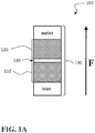
- FIG. 1A is a side schematic view of a variation of a co-catalyst system of the present disclosure
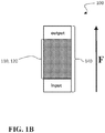
- FIG. 1B is a side schematic view of another variation of the co-catalyst system
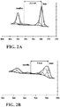
- FIG. 2A is a Co2p 3/2 x-ray photoelectron spectroscopy (XPS) spectrum of a LaBaCoO 4 layered oxide;
- FIG. 2B is a Fe2p 3/2 XPS of a LaBaCoO 4 layered oxide
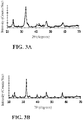
- FIG. 3A is an x-ray diffraction (XRD) pattern of the layered oxide of FIG. 2A ;
- FIG. 3B is an XRD pattern of the layered oxide of FIG. 2B ;
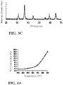
- FIG. 3C is an XRD pattern of Ni 0.15 Co 0.85 CoAlO 4 spinel
- FIG. 4A is a plot of NO conversion percentage as a function of temperature for LaBaCoO 4 ;
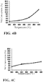
- FIG. 4B is a plot of NO conversion percentage as a function of temperature for LaBaFeO 4 ;
- FIG. 4C is a plot of NO conversion percentage as a function of temperature for Ni 0.15 Co 0.85 CoAlO 4 ;
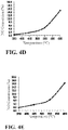
- FIG. 4D is a plot of NO conversion percentage as a function of temperature for a co-catalyst system having LaBaCoO 4 +Ni 0.15 Co 0.85 CoAlO 4 ;
- FIG. 4E is a plot of NO conversion percentage as a function of temperature for a co-catalyst system having LaBaFeO 4 +Ni 0.15 Co 0.85 CoAlO 4 ;
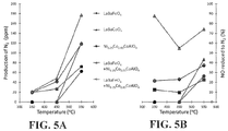
- FIGS. 5A and 5B plot production of N 2 and percentage of NO reduced to N 2 , respectively, by various catalyst compositions.
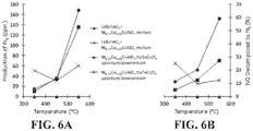
- FIGS. 6A and 6B are plots of N 2 production and percentage of decomposed NO converted to N 2 , respectively, for various alternative co-catalyst configurations.
- the present teachings provide two-stage catalysts for the removal of nitrogen oxides (NO x ) from an exhaust gas stream.
- the presently disclosed two-stage catalysts employ a two-step chemical transformation to decompose NO x to nitrogen and oxygen gas, even at relatively low temperature.
- the presently disclosed two-stage catalysts include a layered oxide, for the decomposition of NO x to N 2 O, and a spinel component, for the decomposition of the N 2 O intermediate to N 2 and O 2 .
- layered oxides are most effective at decomposing NO into N 2 O, not N 2 .
- N 2 O is known for being a major greenhouse gas and powerful pollutant. This characteristic of N 2 O formation makes layered oxides a problematic and non-obvious NO catalytic material, especially at lower temperatures ⁇ 550° C. where layered oxides are not particularly active at N 2 production to offset this N 2 O formation.
- the design of a co-catalyst that purposely uses the layered oxide N 2 O formation to provide a functional advantage is needed.
- the coupling of the layered oxide with a spinel of overlapping temperature range activity for N 2 O decomposition, as described below, allows for the N 2 O generated to be further decomposed to N 2 .
- the decomposition of NO to N 2 is approximately doubled using the co-catalyst design compared to either of the constituent catalysts individually.
- the co-catalyst system 100 includes a layered oxide 110 .
- the layered oxide can include layered oxide nanoparticles.
- the layered oxide 110 can have a formula according to Formula A: La 2-x M x QO 4 A. where M is a cation of at least one Group II metal; Q is a cation of iron, cobalt, nickel, or a combination thereof; and x is a value within a range of about 0.1 to about 1.5, inclusive.
- M can be a cation of strontium, barium, calcium, or a combination thereof.
- the layered oxide can be a layered perovskite oxide, wherein lanthanum and M include divalent cations, and Q includes tetravalent cations.
- the layered oxide 110 can be at least one of LaBaCoO 4 and LaBaFeO 4 .
- the layered oxide will be configured to decompose NO x substantially to N 2 O. Without implying limitation, such decomposition catalyzed by the layered oxide 110 can proceed, for example, through reactions such as shown below in Reactions I and II: 4NO 2 ⁇ 2N 2 O+3O 2 (I) 4NO ⁇ 2N 2 O+O 2 (II)
- the co-catalyst further includes a spinel 120 .
- the spinel 120 can have a formula, Ni y Co 1-y CoAlO 4 , wherein y is a value within a range of about 0.1 to about 0.9, inclusive.
- the spinel 120 can be Ni 0.15 Co 0.85 CoAlO 4 .
- the spinel 120 will be configured to decompose N 2 O to N 2 and O 2 . Without implying limitation, such decomposition catalyzed by the spinel 120 can proceed, for example, through reactions such as shown below in Reaction III: 2N 2 O ⁇ 2N 2 +O 2 (III)
- the layered oxide 110 operates, in part, to partially decompose NO x and produce an intermediate species, N 2 O.
- the spinel 120 then operates to further decompose the intermediate species, N 2 O, to the desired products, N 2 and O 2 .
- the layered oxide 110 and the spinel 120 can be spatially separated from one another, as illustrated in the example of FIG. 1A .
- the layered oxide and spinel 110 , 120 can be in adjacent contact, or, as shown in FIG. 1A , can be separated by a separation space 130 .
- a separation space can be substantially vacant, or can be occupied with a porous, gas permeable, or other suitable material.
- a co-catalyst system 100 of the present disclosure can be deployed in an enclosure 140 having an inlet and an outlet.
- the enclosure 140 can be configured to receive an exhaust gas stream through the inlet and to exit the exhaust gas stream through the outlet, such that the exhaust gas stream has a flow direction (represented by the arrow F in FIGS. 1A and 1B ).
- the layered oxide 110 and spinel 120 are spatially separated ( FIG. 1A )
- the layered oxide 110 can be positioned in an upstream portion of the exhaust gas stream and the spinel 120 can be positioned in a downstream portion of the exhaust gas stream.
- the expression “upstream portion” can refer to a region proximal to a gas inlet portion; and the expression “downstream portion” can refer to a region proximal to a gas outlet portion.
- the layered oxide 110 is positioned in an upstream portion of the exhaust gas stream and the spinel 120 is positioned in a downstream portion of the exhaust gas stream, this can cause the exhaust gas stream to encounter the layered oxide 110 before the exhaust gas stream encounters the spinel 120 .
- the exhaust gas stream flows through the co-catalyst system 100 , it first encounters the layered oxide 110 so that NO x within the exhaust gas stream is substantially or entirely decomposed to N 2 O in consequence.
- the layered oxide and spinel 110 , 120 can be intermixed, substantially occupying the same space, as shown in FIG. 1B .
- the layered oxide and spinel 110 , 120 occupy overlapping regions such that NO x are converted to N 2 O, and N 2 O is converted to N 2 and O 2 , within overlapping regions.
- various intermediate positions can also be employed, such as partial overlap, stepped or gradual concentration gradients, etc.
- a co-catalyst system 100 in which the layered oxide 110 and the spinel 120 are substantially intermixed, as shown in FIG. 1B , can be referred to alternatively as a “mixed co-catalyst”.
- FIGS. 2A and 2B show x-ray photoelectron spectroscopy (XPS) data for two exemplary layered oxides, LaBaCoO 4 and LaBaFeO 4 , respectively.
- the surfaces of the LaBaCoO 4 and LaBaFeO 4 exemplary layered oxides 110 contain Co 3+ and Fe 3+ cations, respectively, based on the XPS binding energy differences between the main and satellite peaks shown in FIGS. 2A and 2B .
- Binding energy differences of 11.5 and 7.8 eV at the 2p 3/2 binding energies are representative of Co 3+ and Fe 3+ , respectively. This is in contrast to the anticipated observation, where binding energy differences between the main and satellite peaks would be ⁇ 4.8 and ⁇ 5.9 eV.
- Powder x-ray diffraction (XRD) patterns for LaBaCoO 4 , LaBaFeO 4 , and Ni 0.15 Co 0.85 CoAlO 4 are shown in FIGS. 3A-3C , respectively.
- Scherrer analysis of the XRD peak broadening for LaBaCoO 4 , LaBaFeO 4 and Ni 0.15 Co 0.85 CoAlO 4 determined crystallite sizes to be 14, 7, and 11 nm, respectively, in these examples.
- FIGS. 4A-E show nitric oxide (NO) conversion percentages for five different catalysts exposed to a nitric oxide stream at varying temperatures, under conditions described below in the Examples section.
- the five catalysts of FIGS. 4A-E are: LaBaCoO 4 only ( FIG. 4A ); LaBaFeO 4 only ( FIG. 4B ); Ni 0.15 Co 0.85 CoAlO 4 only ( FIG. 4C ); a co-catalyst system 100 having LaBaCoO 4 upstream of Ni 0.15 Co 0.85 CoAlO 4 ( FIG. 4D ); and a co-catalyst system 100 having LaBaFeO 4 upstream of Ni 0.15 Co 0.85 CoAlO 4 ( FIG. 4E ). It is to be noted that the total amount of catalyst present is the same in each of the samples corresponding to FIGS. 4A-4E .
- FIG. 4A shows that, while LaBaFeO 4 and LaBaCoO 4 have very comparable NO conversion percentages across the temperature range 350-550° C., LaBaCoO 4 converts about 50% more NO at 650° C. This result suggests that LaBaCoO 4 may be particularly suitable as a layered oxide 110 .
- a comparison to the results in FIG. 4C indicates that the exemplary spinel 120 , by itself, has only half the NO conversion percentage shown by LaBaCoO 4 ( FIG. 4A ) and 75% of that recorded for LaBaFeO 4 ( FIG. 4B ) at 650° C. However, at lower temperatures, the spinel 120 exhibits moderately higher NO conversion percentages than do the layered oxides 110 .
- the co-catalyst systems 100 of FIGS. 4D and 4E are arrayed as shown in FIG. 1A , with the layered oxide 110 upstream and the spinel 120 downstream. It will thus be appreciated that in FIGS. 4D and 4E , the layered oxide 110 (LaBaCoO 4 or LaBaFeO 4 ) is encountered first by the NO gas stream, and the spinel 120 (Ni 0.15 Co 0.85 CoAlO 4 ) is subsequently encountered by the gas stream.
- FIGS. 4A-4E shows that the co-catalysts 100 ( FIGS. 4D and 4E ) have comparable NO decomposition percentages to those of the individual components ( FIGS. 4A-4C ) at lower temperatures, with improved NO decomposition percentages at higher temperatures.
- FIG. 5A illustrates plots of N 2 production by the five catalysts of FIGS. 4A-4E , in the temperature range 350-550° C. It is readily apparent that the two co-catalyst systems 100 produce N 2 as or more efficiently than do the layered oxides 110 or the spinel 120 alone, at all temperatures. The co-catalyst systems 100 produce N 2 more efficiently than do all of the individual components at 450° C. In particular, the layered oxides 110 produce virtually no N 2 in the temperature range 350-450° C. This demonstrates that the NO that is decomposed by these layered oxides 100 alone within that temperature range ( FIGS. 4A and 4B ) is converted to other nitrogen-containing species.
- FIG. 5B illustrates plots of the percentage of NO reduced to N 2 for the same five catalysts, in the temperature range 350-550° C. Stated alternatively, of that portion of NO that is decomposed by a given catalyst at a given temperature ( FIGS. 4A-4E ), FIG. 5B plots the percentage of it that is converted to N 2 , as opposed to another species. Stated yet more succinctly, FIG. 5B shows the N 2 specificity of product formation. The results show that both of the co-catalyst systems 100 have superior N 2 specificity compared to the layered oxides 110 or the spinel 120 alone at 350-450° C. The co-catalyst system 100 having a layered oxide 110 of LaBaCoO 4 , in particular, has superior N 2 specificity at all temperatures, with an approximately 6-fold higher specificity than the spinel 120 alone at the low temperature of 350° C.
- FIGS. 4A-4E and FIGS. 5A-5B generally indicate that deployment of the layered oxide 110 and the spinel 120 in the arrangement of FIG. 1A results in a synergistic effect, and is consistent with the concept of a two-stage catalysis operating through an N 2 O intermediate, as discussed above.
- the results further suggest that LaBaCoO 4 is a particularly effective layered oxide 110 for use in the co-catalyst system 100 .
- FIG. 6A plots N 2 production catalyzed by two mixed co-catalysts and two inverted co-catalysts.
- FIG. 6B shows N 2 specificity of product formation for the same four catalysts.
- the expression “inverted co-catalyst” refers to a catalyst similar to the co-catalyst system as shown in FIG. 1A , but with the positions of layered oxide 110 and spinel 120 reversed relative to the flow direction, F. Stated alternatively, an inverted co-catalyst is one in which the spinel 120 is upstream and the layered oxide 110 is downstream.
- FIGS. 6A-6B A comparison of FIGS. 6A-6B to FIGS. 5A-5B indicates that the co-catalyst systems 100 having intermixed layered oxide 110 and spinel 120 , as in FIG. 1B , are generally less effective than are the co-catalyst systems 100 having layered oxide 110 upstream and spinel 120 downstream, as in FIG. 1A .
- the results further indicate that the inverted co-catalysts are even less effective. This further supports the view that a co-catalyst system 100 of the present disclosure operates through an N 2 O intermediate, as discussed above.
- the method for removal of NO x from an exhaust gas stream includes a step of flowing the exhaust gas stream through a co-catalyst system 100 .
- the co-catalyst system 100 as employed in the method for removal of NO x from an exhaust gas stream, is as described above.
- the flowing step thus includes: (i) exposing the exhaust gas stream to a layered oxide and catalyzing a reduction of at least one of NO and NO 2 to generate N 2 O; and (ii) contacting the exhaust gas stream with a spinel to decompose the N 2 O to N 2 .
- the layered oxide and the spinel are the same in all respects as the layered oxide and spinel as described above.
- the layered oxide has the formula La 2-x M x QO 4
- the spinel has the formula Ni y Co 1-y CoAlO 4 , as described above.
- exposing and “contacting” does not necessarily denote manner of physical interaction between the exhaust gas and the layered oxide is different from the manner of physical interaction between the exhaust gas and the spinel.
- the term “two-stage” as used with respect to the method thus indicates that the exhaust gas stream is exposed to two distinct catalysts, the first catalyst producing, at least in part, an N 2 O intermediate, and the second catalyst producing N 2 .
- exposing the exhaust gas stream to a layered oxide can partially or completely chronologically precede contacting the exhaust gas stream with the spinel.
- the exhaust gas stream will generally encounter the layered oxide prior to the spinel.
- the exhaust gas stream can include a step of recirculating the exhaust gas stream through the co-catalyst system 100 .
- the method includes first exposing the exhaust gas stream to the layered oxide, then contacting the exhaust gas stream with the spinel, then repeating in the same order.
- an exhaust gas stream produced by a manufacturing facility can be recirculated through the co-catalyst system 100 one or more times prior to an eventual release or additional processing.
- the apparatus includes an enclosure; an inlet, configured to receive the exhaust gas stream into the enclosure; and an outlet, configured to allow the exhaust to exit the enclosure.
- the apparatus further includes a co-catalyst system 100 inside the enclosure, and that is as described above.
- the inlet and outlet of the apparatus can generally correspond to the inlet and outlet of FIGS. 1A and/or 1B .
- An example of such an apparatus can be a catalytic converter.
- Example syntheses are conducted under ambient conditions. All chemicals are used as received. With regard to the layered oxides, the metal salt solutions used throughout all of the syntheses are formed most efficiently with sonication. Also, using pre-formed metal salt solutions also dramatically increased the ease of creating reaction emulsions. All emulsions are kept stirring throughout the syntheses so as to avoid any of them breaking. The layered oxide calcination procedures conducted are all done in the same manner for all samples, under a flow of argon with a dwell temperature of 400° C. for 6 hours.
- a solution of 3.5 g NaOH dissolved in 25 mL H 2 O is added to a flask.
- 23 mL n-butanol, 112 mL hexane, 22.5 g cetyltrimethylammonium bromide (CTAB), and a stir bar is then added to this flask.
- the mixture is stirred vigorously to fully dissolve/disperse all components.
- the temperature is increased to 300° C., linearly at 1° C./min, and held for one hour to decarbonize the sample.
- the decarbonized sample is ground thoroughly with an agate mortar and pestle, placed in a furnace, under air, and the temperature is increased to 600° C. at 1° C./min, and held for four hours prior to returning to ambient condition.
- NO decomposition performance is evaluated using a fixed bed quartz tubular reactor (PID Particulate Systems Microactivity Reference) with 1 cm diameter, while flowing 1% NO/He with 1% Ar tracer, over four separate catalyst configurations.
- the configuration corresponding to FIG. 1B (mixed co-catalysts or single component catalysts) is a single bed, composed of a mixture of approximately 500 mg catalyst diluted with 100 mg quartz sand, to yield a bed length of 1 cm while maintaining a GHSV of 2,100 h ⁇ 1 .
- the samples are divided into two separate 1 cm length beds, separated by quartz wool.
- the catalysts Prior to reaction, the catalysts are pretreated in UHP He for 30 minutes at 400° C., and reactions are conducted for two hours each at 350, 450, 550, and 650° C., utilizing only the last 10 minutes of data at each condition.
- An online mass spectrometer (MKS Instruments Inc. Cirrus-2) is utilized to calculate NO conversion by linear interpolation between the base line m/z 30 signal (He flow only), and the m/z 30 signal of the reaction mixture through reactor bypass, while monitoring m/z 28, 32, 40, 44, 46 (N 2 , O 2 , Ar, N 2 O, NO 2 ).
- the calibration curve is utilized to calculate a quantified N 2 production.
- the terms “comprise” and “include” and their variants are intended to be non-limiting, such that recitation of items in succession or a list is not to the exclusion of other like items that may also be useful in the devices and methods of this technology.
- the terms “can” and “may” and their variants are intended to be non-limiting, such that recitation that an embodiment can or may comprise certain elements or features does not exclude other embodiments of the present technology that do not contain those elements or features.
Landscapes
- Chemical & Material Sciences (AREA)
- Engineering & Computer Science (AREA)
- Chemical Kinetics & Catalysis (AREA)
- Materials Engineering (AREA)
- Organic Chemistry (AREA)
- Combustion & Propulsion (AREA)
- Health & Medical Sciences (AREA)
- Environmental & Geological Engineering (AREA)
- Biomedical Technology (AREA)
- Analytical Chemistry (AREA)
- General Chemical & Material Sciences (AREA)
- Oil, Petroleum & Natural Gas (AREA)
- Toxicology (AREA)
- Mechanical Engineering (AREA)
- General Engineering & Computer Science (AREA)
- Dispersion Chemistry (AREA)
- Catalysts (AREA)
Abstract
Description
La2-xMxQO4 A.
where M is a cation of at least one Group II metal; Q is a cation of iron, cobalt, nickel, or a combination thereof; and x is a value within a range of about 0.1 to about 1.5, inclusive. In some implementations, M can be a cation of strontium, barium, calcium, or a combination thereof. In certain implementations, the layered oxide can be a layered perovskite oxide, wherein lanthanum and M include divalent cations, and Q includes tetravalent cations.
4NO2→2N2O+3O2 (I)
4NO→2N2O+O2 (II)
2N2O→2N2+O2 (III)
Claims (14)
Priority Applications (1)
| Application Number | Priority Date | Filing Date | Title |
|---|---|---|---|
| US16/435,773 US10857504B2 (en) | 2017-03-31 | 2019-06-10 | Two-stage catalyst for removal of NOx from exhaust gas stream |
Applications Claiming Priority (2)
| Application Number | Priority Date | Filing Date | Title |
|---|---|---|---|
| US15/476,374 US10316722B2 (en) | 2017-03-31 | 2017-03-31 | Two-stage catalyst for removal of NOx from exhaust gas stream |
| US16/435,773 US10857504B2 (en) | 2017-03-31 | 2019-06-10 | Two-stage catalyst for removal of NOx from exhaust gas stream |
Related Parent Applications (1)
| Application Number | Title | Priority Date | Filing Date |
|---|---|---|---|
| US15/476,374 Continuation-In-Part US10316722B2 (en) | 2017-03-31 | 2017-03-31 | Two-stage catalyst for removal of NOx from exhaust gas stream |
Publications (2)
| Publication Number | Publication Date |
|---|---|
| US20190291051A1 US20190291051A1 (en) | 2019-09-26 |
| US10857504B2 true US10857504B2 (en) | 2020-12-08 |
Family
ID=67983341
Family Applications (1)
| Application Number | Title | Priority Date | Filing Date |
|---|---|---|---|
| US16/435,773 Active US10857504B2 (en) | 2017-03-31 | 2019-06-10 | Two-stage catalyst for removal of NOx from exhaust gas stream |
Country Status (1)
| Country | Link |
|---|---|
| US (1) | US10857504B2 (en) |
Citations (15)
| Publication number | Priority date | Publication date | Assignee | Title |
|---|---|---|---|---|
| US6023929A (en) * | 1995-08-26 | 2000-02-15 | Ford Global Technologies, Inc. | Engine with cylinder deactivation |
| US6378359B1 (en) * | 2000-01-07 | 2002-04-30 | Ford Global Technologies, Inc. | Method and system for evaluating exhaust on-board diagnostics system |
| US7146802B2 (en) | 2004-10-07 | 2006-12-12 | General Motors Corporation | Reducing NOx emissions with a staged catalyst |
| US20070044444A1 (en) * | 2004-11-26 | 2007-03-01 | Yukio Oshimi | Honeycomb structured body |
| US20070116870A1 (en) * | 1996-06-21 | 2007-05-24 | Engelhard Corporation | Monolithic Catalysts and Related Process for Manufacture |
| KR20110055024A (en) * | 2009-11-19 | 2011-05-25 | 현대자동차주식회사 | Catalysts for gasoline vehicles to improve low temperature activity |
| US20130149225A1 (en) * | 2010-06-04 | 2013-06-13 | Thyssenkrupp Uhde Gmbh | Process and Apparatus for Eliminating NOx and N2O |
| US20130312407A1 (en) | 2012-05-25 | 2013-11-28 | Ford Global Technologies, Llc | Exhaust air injection |
| US20140171302A1 (en) * | 2012-12-18 | 2014-06-19 | Hyundai Motor Company | Lnt catalyst with enhanced nitrogen oxide storage capacity at low temperature |
| US8883102B1 (en) * | 2014-01-14 | 2014-11-11 | Ford Global Technologies, Llc | Methods for controlling nitrous oxide emissions |
| US20140363359A1 (en) * | 2011-12-16 | 2014-12-11 | Thyssenkrupp Industrial Solutions Ag | Device and method for eliminating nox and n2o |
| US20150148216A1 (en) | 2013-11-26 | 2015-05-28 | Clean Diesel Technologies, Inc. | Spinel compositions and applications thereof |
| US20150375207A1 (en) * | 2013-02-14 | 2015-12-31 | Haldor Topsoe A/S | Method and catalyst for the simultaneous removal of carbon monoxide and nitrogen oxides from flue or exhaust gas |
| US20170362984A1 (en) * | 2014-12-08 | 2017-12-21 | Basf Corporation | Nitrous oxide removal catalysts for exhaust systems |
| US20180283251A1 (en) | 2017-03-31 | 2018-10-04 | Toyota Motor Engineering & Manufacturing North America, Inc. | TWO-STAGE CATALYST FOR REMOVAL OF NOx FROM EXHAUST GAS STREAM |
-
2019
- 2019-06-10 US US16/435,773 patent/US10857504B2/en active Active
Patent Citations (16)
| Publication number | Priority date | Publication date | Assignee | Title |
|---|---|---|---|---|
| US6023929A (en) * | 1995-08-26 | 2000-02-15 | Ford Global Technologies, Inc. | Engine with cylinder deactivation |
| US20070116870A1 (en) * | 1996-06-21 | 2007-05-24 | Engelhard Corporation | Monolithic Catalysts and Related Process for Manufacture |
| US6378359B1 (en) * | 2000-01-07 | 2002-04-30 | Ford Global Technologies, Inc. | Method and system for evaluating exhaust on-board diagnostics system |
| US7146802B2 (en) | 2004-10-07 | 2006-12-12 | General Motors Corporation | Reducing NOx emissions with a staged catalyst |
| US20070044444A1 (en) * | 2004-11-26 | 2007-03-01 | Yukio Oshimi | Honeycomb structured body |
| KR20110055024A (en) * | 2009-11-19 | 2011-05-25 | 현대자동차주식회사 | Catalysts for gasoline vehicles to improve low temperature activity |
| US20130149225A1 (en) * | 2010-06-04 | 2013-06-13 | Thyssenkrupp Uhde Gmbh | Process and Apparatus for Eliminating NOx and N2O |
| US20140363359A1 (en) * | 2011-12-16 | 2014-12-11 | Thyssenkrupp Industrial Solutions Ag | Device and method for eliminating nox and n2o |
| US20130312407A1 (en) | 2012-05-25 | 2013-11-28 | Ford Global Technologies, Llc | Exhaust air injection |
| US20140171302A1 (en) * | 2012-12-18 | 2014-06-19 | Hyundai Motor Company | Lnt catalyst with enhanced nitrogen oxide storage capacity at low temperature |
| US20150375207A1 (en) * | 2013-02-14 | 2015-12-31 | Haldor Topsoe A/S | Method and catalyst for the simultaneous removal of carbon monoxide and nitrogen oxides from flue or exhaust gas |
| US20150148216A1 (en) | 2013-11-26 | 2015-05-28 | Clean Diesel Technologies, Inc. | Spinel compositions and applications thereof |
| US9511358B2 (en) * | 2013-11-26 | 2016-12-06 | Clean Diesel Technologies, Inc. | Spinel compositions and applications thereof |
| US8883102B1 (en) * | 2014-01-14 | 2014-11-11 | Ford Global Technologies, Llc | Methods for controlling nitrous oxide emissions |
| US20170362984A1 (en) * | 2014-12-08 | 2017-12-21 | Basf Corporation | Nitrous oxide removal catalysts for exhaust systems |
| US20180283251A1 (en) | 2017-03-31 | 2018-10-04 | Toyota Motor Engineering & Manufacturing North America, Inc. | TWO-STAGE CATALYST FOR REMOVAL OF NOx FROM EXHAUST GAS STREAM |
Non-Patent Citations (9)
| Title |
|---|
| Belt, J. et al., "Calendar and PHEV Cycle life aging of high-energy, lithium-ion cells containing blended spinel and layered-oxide cathodes," Journal of Power Sources, vol. 196, Iss. 23, (Dec. 1, 2011) pp. 10213-10221. |
| Clement, R. et al., "Review-Manganese-Based P2-Type Transition Metal Oxides as Sodium-Ion Battery Cathode Materials," Journal of the Electrochemical Society, 162(14) (2015) pp. A2589-A2604. |
| Clement, R. et al., "Review—Manganese-Based P2-Type Transition Metal Oxides as Sodium-Ion Battery Cathode Materials," Journal of the Electrochemical Society, 162(14) (2015) pp. A2589-A2604. |
| Pan, K.L. et al., "Direct N2O decomposition over La2NiO4-based perovskite-type oxides", Journal of the Air & Waste Management Association 64 (2014) pp. 1260-1269. |
| Zhang, Chi, et al. "Catalytic Decomposition of N2O . . . " Chem. Cat., 8. 2155-2164 (2016) (Year: 2016). * |
| Zhang, H.J. et al., "Catalytic decomposition of N2O over NixCo1-xAlO4 spinel oxides prepared by sol-gel method", Journal of Fuel Chemistry and Technology 43 (2015) pp. 81-87. |
| Zhu, J. et al., "Effect of Ce on NO direct decomposition in the absence/presence of O2 over La1-xCexSrNiO4 (0≤x≤0.3)", Journal of Molecular Catalysis A: Chemical 234 (2005) p. 9. |
| Zhu, J. et al., "Study of La2-xSrxCuO4 (x=0.0, 0.5, 1.0) catalysts for NO + CO reaction form the measurements of O2-TPD, H2 TPD and cyclic voltammetry", Journal of Molecular Catalysis A: Chemical 238 (2005) p. 35. |
| Zhu, Y. et al., "Direct NO decomposition over La2 xBaxNiO4 catalysts containing BaCO3 phase", Applied Catalysis B: Environmental 82 (2008) pp. 255-263. |
Also Published As
| Publication number | Publication date |
|---|---|
| US20190291051A1 (en) | 2019-09-26 |
Similar Documents
| Publication | Publication Date | Title |
|---|---|---|
| Zhang et al. | Design of high-performance iron–niobium composite oxide catalysts for NH3-SCR: Insights into the interaction between Fe and Nb | |
| Mu et al. | Inductive Effect Boosting Catalytic Performance of Advanced Fe1–x V x Oδ Catalysts in Low-Temperature NH3 Selective Catalytic Reduction: Insight into the Structure, Interaction, and Mechanisms | |
| Xie et al. | Copper single atom-triggered niobia–ceria catalyst for efficient low-temperature reduction of nitrogen oxides | |
| Yang et al. | Hexavalent metal cations doped into ceria inducing the formation of binuclear sites Ce3+–O–Ce3+ to boost the NH3-SCR reaction | |
| Li et al. | Insight into the combined catalytic removal properties of Pd modification V/TiO2 catalysts for the nitrogen oxides and benzene by: an experiment and DFT study | |
| EP3409360A1 (en) | Hybrid binary catalysts, methods and uses thereof | |
| Li et al. | Performance of K and Ni substituted La1− xKxCo1− yNiyO3− δ perovskite catalysts used for soot combustion, NOx storage and simultaneous NOx-soot removal | |
| US20180296978A1 (en) | COPPER OXIDES SUPPORTED ON SPINEL OXIDES AS CATALYSTS FOR LOW TEMPERATURE DIRECT NOx DECOMPOSITION | |
| JP2013503731A (en) | Method for producing SCR active zeolite catalyst and SCR active zeolite catalyst | |
| US10316722B2 (en) | Two-stage catalyst for removal of NOx from exhaust gas stream | |
| Kwon et al. | Influence of support composition on enhancing the performance of Ce-V on TiO2 comprised tungsten-silica for NH3-SCR | |
| Xue et al. | Investigation of the hydrothermal aging of an Mn-based mullite SmMn 2 O 5 catalyst of NO oxidation | |
| CN113559850A (en) | Manganese-based composite oxide catalyst and preparation method and use thereof | |
| Zheng et al. | Promotional role of Co on Cu-SAPO-34 towards enhanced denitration performance and SO2 tolerance | |
| CN113874109A (en) | Denitration catalyst and method for producing the same | |
| Li et al. | Highly Efficient RuO x/NbO x-ZrO x Catalysts for Ammonia Removal via Tuning Acidic Active Species | |
| CN105561977A (en) | Metal tungstates for use as nitrogen oxides reduction catalysts | |
| Yin et al. | Investigation of graphic carbon nitride supported Ag-modified cobalt oxides for N2O decomposition at low temperature | |
| US10857504B2 (en) | Two-stage catalyst for removal of NOx from exhaust gas stream | |
| JP2005081189A (en) | Catalyst for denitrifying high temperature waste gas | |
| Zhang et al. | Reasonably designed CuSbTiO x series catalysts with high NH 3-SCR activity and obviously improved SO 2 tolerance | |
| CN111545055B (en) | Application of hydrotalcite-like compound derived composite oxide material | |
| US10596519B1 (en) | Modified ferrite catalysts for direct no decomposition and a method of making and using a catalyst | |
| Li et al. | Surface reconstruction-induced heterostructures in La0. 5Sr0. 5MnO3 for stable oxygen vacancies and enhanced hydrolysis-assisted oxidation of chlorobenzene | |
| US11110432B2 (en) | Multi-transition metal doped copper-cobalt spinel catalyst material for NOx decomposition |
Legal Events
| Date | Code | Title | Description |
|---|---|---|---|
| FEPP | Fee payment procedure |
Free format text: ENTITY STATUS SET TO UNDISCOUNTED (ORIGINAL EVENT CODE: BIG.); ENTITY STATUS OF PATENT OWNER: LARGE ENTITY |
|
| AS | Assignment |
Owner name: TOYOTA MOTOR ENGINEERING & MANUFACTURING NORTH AME Free format text: ASSIGNMENT OF ASSIGNORS INTEREST;ASSIGNORS:PECK, TORIN C.;ROWE, MICHAEL PAUL;JONES, MICHAEL;REEL/FRAME:049568/0775 Effective date: 20190607 Owner name: TOYOTA MOTOR ENGINEERING & MANUFACTURING NORTH AMERICA, INC., TEXAS Free format text: ASSIGNMENT OF ASSIGNORS INTEREST;ASSIGNORS:PECK, TORIN C.;ROWE, MICHAEL PAUL;JONES, MICHAEL;REEL/FRAME:049568/0775 Effective date: 20190607 |
|
| STPP | Information on status: patent application and granting procedure in general |
Free format text: DOCKETED NEW CASE - READY FOR EXAMINATION |
|
| STPP | Information on status: patent application and granting procedure in general |
Free format text: NON FINAL ACTION MAILED |
|
| STPP | Information on status: patent application and granting procedure in general |
Free format text: RESPONSE TO NON-FINAL OFFICE ACTION ENTERED AND FORWARDED TO EXAMINER |
|
| STPP | Information on status: patent application and granting procedure in general |
Free format text: NOTICE OF ALLOWANCE MAILED -- APPLICATION RECEIVED IN OFFICE OF PUBLICATIONS |
|
| STCF | Information on status: patent grant |
Free format text: PATENTED CASE |
|
| AS | Assignment |
Owner name: TOYOTA JIDOSHA KABUSHIKI KAISHA, JAPAN Free format text: ASSIGNMENT OF ASSIGNORS INTEREST;ASSIGNOR:TOYOTA MOTOR ENGINEERING & MANUFACTURING NORTH AMERICA, INC.;REEL/FRAME:054916/0292 Effective date: 20201208 |
|
| CC | Certificate of correction | ||
| MAFP | Maintenance fee payment |
Free format text: PAYMENT OF MAINTENANCE FEE, 4TH YEAR, LARGE ENTITY (ORIGINAL EVENT CODE: M1551); ENTITY STATUS OF PATENT OWNER: LARGE ENTITY Year of fee payment: 4 |