US10857254B2 - Protective pipe for a UV tube, in particular a UV-C tube - Google Patents

Protective pipe for a UV tube, in particular a UV-C tube Download PDF

Info

Publication number
US10857254B2
US10857254B2 US15/561,102 US201615561102A US10857254B2 US 10857254 B2 US10857254 B2 US 10857254B2 US 201615561102 A US201615561102 A US 201615561102A US 10857254 B2 US10857254 B2 US 10857254B2
Authority
US
United States
Prior art keywords
protective pipe
pipe
tube
hose
radiation
Prior art date
Legal status (The legal status is an assumption and is not a legal conclusion. Google has not performed a legal analysis and makes no representation as to the accuracy of the status listed.)
Active
Application number
US15/561,102
Other versions
US20180117208A1 (en
Inventor
Martin Graupner
Simon Schlegel
Current Assignee (The listed assignees may be inaccurate. Google has not performed a legal analysis and makes no representation or warranty as to the accuracy of the list.)
Sterilair AG
Original Assignee
Sterilair AG
Priority date (The priority date is an assumption and is not a legal conclusion. Google has not performed a legal analysis and makes no representation as to the accuracy of the date listed.)
Filing date
Publication date
Application filed by Sterilair AG filed Critical Sterilair AG
Assigned to STERILAIR AG reassignment STERILAIR AG ASSIGNMENT OF ASSIGNORS INTEREST (SEE DOCUMENT FOR DETAILS). Assignors: GRAUPNER, MARTIN, SCHLEGEL, SIMON
Publication of US20180117208A1 publication Critical patent/US20180117208A1/en
Application granted granted Critical
Publication of US10857254B2 publication Critical patent/US10857254B2/en
Active legal-status Critical Current
Anticipated expiration legal-status Critical

Links

Images

Classifications

    • AHUMAN NECESSITIES
    • A61MEDICAL OR VETERINARY SCIENCE; HYGIENE
    • A61LMETHODS OR APPARATUS FOR STERILISING MATERIALS OR OBJECTS IN GENERAL; DISINFECTION, STERILISATION OR DEODORISATION OF AIR; CHEMICAL ASPECTS OF BANDAGES, DRESSINGS, ABSORBENT PADS OR SURGICAL ARTICLES; MATERIALS FOR BANDAGES, DRESSINGS, ABSORBENT PADS OR SURGICAL ARTICLES
    • A61L9/00Disinfection, sterilisation or deodorisation of air
    • A61L9/16Disinfection, sterilisation or deodorisation of air using physical phenomena
    • A61L9/18Radiation
    • A61L9/20Ultraviolet radiation
    • HELECTRICITY
    • H01ELECTRIC ELEMENTS
    • H01JELECTRIC DISCHARGE TUBES OR DISCHARGE LAMPS
    • H01J61/00Gas-discharge or vapour-discharge lamps
    • H01J61/02Details
    • H01J61/30Vessels; Containers
    • H01J61/34Double-wall vessels or containers
    • AHUMAN NECESSITIES
    • A61MEDICAL OR VETERINARY SCIENCE; HYGIENE
    • A61LMETHODS OR APPARATUS FOR STERILISING MATERIALS OR OBJECTS IN GENERAL; DISINFECTION, STERILISATION OR DEODORISATION OF AIR; CHEMICAL ASPECTS OF BANDAGES, DRESSINGS, ABSORBENT PADS OR SURGICAL ARTICLES; MATERIALS FOR BANDAGES, DRESSINGS, ABSORBENT PADS OR SURGICAL ARTICLES
    • A61L2/00Methods or apparatus for disinfecting or sterilising materials or objects other than foodstuffs or contact lenses; Accessories therefor
    • A61L2/02Methods or apparatus for disinfecting or sterilising materials or objects other than foodstuffs or contact lenses; Accessories therefor using physical phenomena
    • A61L2/08Radiation
    • A61L2/10Ultraviolet radiation
    • FMECHANICAL ENGINEERING; LIGHTING; HEATING; WEAPONS; BLASTING
    • F21LIGHTING
    • F21VFUNCTIONAL FEATURES OR DETAILS OF LIGHTING DEVICES OR SYSTEMS THEREOF; STRUCTURAL COMBINATIONS OF LIGHTING DEVICES WITH OTHER ARTICLES, NOT OTHERWISE PROVIDED FOR
    • F21V7/00Reflectors for light sources
    • F21V7/005Reflectors for light sources with an elongated shape to cooperate with linear light sources
    • HELECTRICITY
    • H01ELECTRIC ELEMENTS
    • H01JELECTRIC DISCHARGE TUBES OR DISCHARGE LAMPS
    • H01J61/00Gas-discharge or vapour-discharge lamps
    • H01J61/02Details
    • H01J61/50Auxiliary parts or solid material within the envelope for reducing risk of explosion upon breakage of the envelope, e.g. for use in mines

Definitions

  • the invention relates to a protective pipe for a UV lamp for accommodation of a tube having a rod-shaped encasing pipe, wherein a viewing window is provided on the circumferential surface, through which viewing window the radiation, particularly UV-C radiation, emitted by the tube can exit. Furthermore, it relates to the use of polytetrafluoroethylene for a UV lamp.
  • UV means ultraviolet with reference to this application, and is used for characterization of a defined wavelength range.
  • UV-C UV-C
  • UV sterilization acts, in particular, on bacteria, viruses, yeasts and molds. These microorganisms are effectively inactivated by means of what is called UV disinfection of air, water or surfaces.
  • the technology of UV sterilization does not utilize any chemistry and no toxic compounds, and does not lead to mutation-related resistance formation.
  • the undesirable microorganisms become inactive within seconds, while the product properties of the irradiated product remain almost unchanged. UV sterilization is particularly used in the sectors in which great demands exist with regard to consumer protection and requirements based on the HACCP concept.
  • Ultraviolet radiation is very energy-rich and triggers photochemical reactions in the respective nucleic acids of the exposed cell when the radiation is absorbed. If two thymines lie next to one another in the DNA strand, they react and form a dimer that is unusable for duplication and transcription. If multiple damage occurs, the cell is no longer able to regenerate. It loses the ability to divide and reproduce, and dies.
  • UV dose that leads to inactivation of the microorganisms differs by species, in this regard. While the predominant part of bacteria and viruses become inactive at a relatively slight dose, yeasts, molds, fungi, and spores require a correspondingly higher dose.
  • Short-wave UV-C radiation can be shielded against with usual window glass, transparent plastic, such as Makrolon® or acrylic glass, for example, as well as practically all non-transparent materials.
  • UV-C sterilization is particularly used in the foods-processing industry. Special demands are set for the UV-C source, on the basis of the environment in which the radiation sources are used. It must at least satisfy the IP52 standard.
  • the UV-C source is generally surrounded by an encasing pipe.
  • This encasing pipe consists of a quartz glass that surrounds the radiation source.
  • the encasing pipe with the UV source and the corresponding connectors forms the tube. If a UV-C source is provided, one also speaks of a UV-C tube.
  • the electrical connectors i.e. the connection from the UV-C source to a current connector, is formed by a socket that has corresponding electrical contacts, preferably pins. These are plugged into a holder, in the manner of a plug, in order to produce electrical contacts.
  • a protective pipe surrounds the encasing pipe.
  • This protective pipe consist of a basic body composed of stainless steel or aluminum, preferably having rotation symmetry, and is dimensioned in such a manner that this basic body surrounds the encasing pipe at a distance.
  • a viewing window is provided on the circumferential surface, from which the radiation emitted by the radiation source exits.
  • This viewing window is generally milled or lasered.
  • the inner wall of the protective pipe has a reflector, in such a manner that the radiation emitted passes through the viewing window at least in partially concentrated manner.
  • This reflector generally consists of an aluminum layer or an aluminum alloy, such as aluminum/manganese, for example.
  • an elongated UV light source is proposed as a radiation source, which is surrounded by an extremely reflective casing.
  • This casing is a plastic pipe that has an aperture opening. The size of this aperture opening is defined.
  • the casing is structured in such a manner that it is thin with regard to its wall, so that the radiation that is not reflected, and is converted to heat, can exit directly from the casing, because this has a negative influence on the power of the UV source.
  • Aluminum or aluminum alloy has a degree of reflection of approximately 87-89%. As a result, the emitted power is low, and corresponding losses occur as a result.
  • the task of the invention consists of increasing the emitted power of the UV-C tube, without changing the tube or the UV source and without losing the advantages of the protective pipe.
  • the first part of the basic idea of the solution consists in using a material that demonstrates better reflection in comparison with aluminum or the aluminum alloy, in order to thereby increase the emitted power from the viewing window.
  • the solution consists in using polytetrafluoroethylene (abbreviated PTFE, occasionally also polytetrafluoroethane), as the reflector material. Colloquially, this plastic is often identified with the trade name Teflon®.
  • PTFE polytetrafluoroethylene
  • Teflon® Teflon®
  • a surrounding transparent hose also protects the encasing pipe, which would be freely accessible through the viewing window as such.
  • the transmission capacity is only slightly influenced by the selection of the material of the protective hose.
  • the basic idea of the invention is to use a material that demonstrates almost uniformly high reflection properties over a wavelength bandwidth from 1000 nm to 250 nm as the reflection material for the reflector.
  • Polytetrafluoroethylene demonstrates these properties.
  • a preferred solution consists in using polytetrafluoroethylene in an optically pure white grade, as a diffusively reflective coating. Colloquially, this is also called optical PTFE.
  • the polytetrafluoroethylene consists of a layer of up to 2 mm and has reflection properties of more than 97%, specifically over the bandwidth from 1000 nm to 250 nm. It is preferably white and heat-resistant up to about 250-260° C.; it is non-combustible.
  • a further significant advantage in the use of polytetrafluoroethylene as the reflection material can be seen in that the material has a heat-insulating effect.
  • the effect consists, among other things, in that the emitted power is far below standard. In this manner, the UV source can now be used also in a cold temperature environment, or one with an alternating temperature, so that a broad application spectrum occurs, with great power efficiency.
  • a reflector can be additionally introduced, with an aluminum body that is easy to produce, which reflector guides at least part of the emitted rays of the UV source in the direction of a viewing window provided in the protective pipe.
  • the viewing window extends in the longitudinal direction, over part of the mantle surface of the protective pipe.
  • This reflector can have a high degree of reflection in that it is disposed rotationally around the encasing pipe (the material can be formed in this manner and does not have to be configured in facet-like manner), and consists of a material that possesses a high degree of reflection.
  • a further advantage when using polytetrafluoroethylene lies in that it can be affixed very close to the UV lamp, because it very precisely follows the cylindrical shape of the encasing pipe.
  • the gap between the encasing pipe and the reflector is small, as a result. This additionally increases the reflection power. Furthermore, an additional heat effect occurs, which is beneficial with regard to the emitted power.
  • the region of the viewing window is covered by a transparent material. Because this viewing window or any other aperture opening, as well, offers a possibility for influences from the environment, such as temperature, dirt, etc. to nevertheless penetrate into the protective pipe, but also the temperature in the protective pipe, which is advantageously constant, cannot be maintained, it is provided to dispose a transparent polytetrafluoroethylene hose over the entire encasing pipe, part of which hose covers the viewing window. Since polytetrafluoroethylene has a very low index of refraction, the deflection or also reflection of the UV radiation that exits from the viewing window and is emitted through the hose is very slight. The hose therefore encases the entire protective pipe and ends in the threaded region at the sides, in each instance. Because this hose is also tear-resistant, unintentional “breaking into” the viewing window cannot take place.
  • the hose over the protective pipe can simply be drawn over it in the manner of a bag, and heat-shrunk onto it, so that close contact with the protective pipe is achieved, without liquid or moisture, for example, being able to get between the inner side of the hose and the outer side of the protective pipe.
  • a transparent plastic hose with a corresponding tear resistance can also be drawn on and heat-shrunk on.
  • a lens can also be set in front of the viewing window, by means of the formation of a hose, so that the emitted rays are focused or can be output from the viewing window in diffuse manner.
  • FIG. 1 a perspective view of the UV lamp with protective pipe, as an example, in an exploded representation
  • FIG. 2 a perspective view of the protective pipe according to the invention
  • FIG. 3 a perspective view of the protective pipe, as well as a hose that surrounds the protective pipe, partly in section.
  • a UV lamp 1 is shown.
  • This UV lamp 1 consists of a UV tube 2 , which in turn comprises a socket 3 with an electrical connector 4 .
  • a UV source is coupled with the socket 3 ; the source is not shown in any detail in the drawing.
  • the UV source is surrounded by a rod-shaped encasing pipe 5 .
  • the encasing pipe 5 generally consists of a quartz glass.
  • the end of the UV tube 2 that lies opposite the socket 3 has an end element 6 .
  • a protective pipe 8 having a circumferential surface 7 surrounds the encasing pipe 5 .
  • the protective pipe 8 has rotation symmetry and is open at both its end faces. In this way, it is possible to push the protective pipe 8 over the encasing pipe 5 .
  • the protective pipe 8 has elements 9 on both sides, which each interact with inside threads 10 within the protective pipe 8 , so that the UV tube 2 can be firmly positioned within the protective pipe 8 .
  • Alternative attachment means for the elements 9 are also conceivable, such as, for example, a magnetic closure, bayonet closure, etc.
  • the protective pipe 8 as also shown in FIG. 2 —furthermore has a viewing window 11 .
  • This viewing window 11 extends over a partial region of the circumferential surface 7 of the protective pipe 8 .
  • This viewing window 11 gives access to the encasing pipe 5 and has no transparent covering. This brings with it the advantage that the radiation 12 of the UV source, which is emitted out of the encasing pipe 5 , is released in the direction shown.
  • the coating 13 of polytetrafluoroethylene is affixed within the protective pipe 8 and forms a reflector 14 .
  • a major portion (approximately 95%) of the radiation emitted from the protective pipe 8 is reflected into the environment by way of the reflector.
  • the reflector 14 can be shaped to fit the encasing pipe 5 . Furthermore, very close contact with the encasing pipe 5 is possible, because a facet-like configuration, as it is known when using aluminum, is eliminated.
  • FIG. 3 a perspective view of the protective pipe 8 according to FIG. 2 is shown, but with the difference that this pipe is surrounded by a protective hose 15 .
  • This protective hose 15 surrounds the protective pipe 8 completely and lies closely against its circumferential surface 7 .
  • This protective hose 15 extends over the free ends of the protective pipe 8 , and is accommodated by the elements 9 , together with the corresponding seals. The seals lie closely against the outer wall of the protective hose 15 . In this way, the encasing pipe 5 that lies on the inside is completely sealed off.
  • the UV source is exposed to extreme environmental conditions, dirt also cannot get to the encasing pipe from the outside, since the viewing window 11 is completely covered by the hose 15 , which consists of transparent material.
  • the material is selected in such a manner that the emitted radiation 12 is not influenced or is only influenced slightly.
  • a transparent Teflon material is proposed, since this is also extremely tear-resistant.
  • a protective pipe 8 having a reflector 14 as well as a hose 15 that surrounds the protective pipe 8 is made available, which pipe provides uniform UV radiation quality and power almost independent of the field of use, with reference to the environment, because it was surprisingly found that a constant local environment for the radiation source has a significant influence on the emitted radiation power. Furthermore, such a UV source can also be used in critical areas, for example the foods industry.

Landscapes

  • Health & Medical Sciences (AREA)
  • Epidemiology (AREA)
  • Life Sciences & Earth Sciences (AREA)
  • Animal Behavior & Ethology (AREA)
  • General Health & Medical Sciences (AREA)
  • Public Health (AREA)
  • Veterinary Medicine (AREA)
  • Engineering & Computer Science (AREA)
  • General Engineering & Computer Science (AREA)
  • Apparatus For Disinfection Or Sterilisation (AREA)

Abstract

A protective pipe for a UV lamp for accommodating a tube includes a rod-shaped encasing pipe, wherein a viewing window is provided on the circumferential surface, through which viewing window the radiation, in particular the UV-C radiation, emitted by the tube can escape. A coating made of polytetrafluoroethylene is applied to the inner face of the protective pipe as a reflector. The protective pipe is composed of metal and is surrounded, at least in the region of the viewing window, by an at least partially transparent hose composed of plastic. Preferably, a transparent Teflon material is proposed for the hose.

Description

CROSS REFERENCE TO RELATED APPLICATIONS
This application is the National Stage of PCT/IB2016/051967 filed on Apr. 7, 2016, which claims priority under 35 U.S.C. § 119 of German Application No. 102015105362.4 filed on Apr. 9, 2015, the disclosure of which is incorporated by reference. The international application under PCT article 21(2) was not published in English.
TECHNICAL FIELD
The invention relates to a protective pipe for a UV lamp for accommodation of a tube having a rod-shaped encasing pipe, wherein a viewing window is provided on the circumferential surface, through which viewing window the radiation, particularly UV-C radiation, emitted by the tube can exit. Furthermore, it relates to the use of polytetrafluoroethylene for a UV lamp.
DEFINITIONS
UV means ultraviolet with reference to this application, and is used for characterization of a defined wavelength range.
Ultraviolet rays form part of the natural sunlight spectrum. Short-wave ultraviolet rays belong to the group of optical rays. Nevertheless, they are invisible for the human eye. The UV rays from what is called the C band (therefore referred to as UV-C) have a strong germicidal effect around 260 nm (nanometers). The kill rate is subject to the dose/effect principle; for this reason, technical characteristic data regarding tube power and the irradiation period are decisive for functionally reliable UV-C sterilization.
The germicidal effect acts, in particular, on bacteria, viruses, yeasts and molds. These microorganisms are effectively inactivated by means of what is called UV disinfection of air, water or surfaces. The technology of UV sterilization does not utilize any chemistry and no toxic compounds, and does not lead to mutation-related resistance formation. The undesirable microorganisms become inactive within seconds, while the product properties of the irradiated product remain almost unchanged. UV sterilization is particularly used in the sectors in which great demands exist with regard to consumer protection and requirements based on the HACCP concept.
Ultraviolet radiation is very energy-rich and triggers photochemical reactions in the respective nucleic acids of the exposed cell when the radiation is absorbed. If two thymines lie next to one another in the DNA strand, they react and form a dimer that is unusable for duplication and transcription. If multiple damage occurs, the cell is no longer able to regenerate. It loses the ability to divide and reproduce, and dies.
From economic aspects, germ reduction all the way to the 5-log stage is possible. The precise UV dose that leads to inactivation of the microorganisms differs by species, in this regard. While the predominant part of bacteria and viruses become inactive at a relatively slight dose, yeasts, molds, fungi, and spores require a correspondingly higher dose.
Short-wave UV-C radiation can be shielded against with usual window glass, transparent plastic, such as Makrolon® or acrylic glass, for example, as well as practically all non-transparent materials.
STATE OF THE ART
UV-C sterilization is particularly used in the foods-processing industry. Special demands are set for the UV-C source, on the basis of the environment in which the radiation sources are used. It must at least satisfy the IP52 standard.
The UV-C source is generally surrounded by an encasing pipe. This encasing pipe consists of a quartz glass that surrounds the radiation source. The encasing pipe with the UV source and the corresponding connectors forms the tube. If a UV-C source is provided, one also speaks of a UV-C tube. The electrical connectors, i.e. the connection from the UV-C source to a current connector, is formed by a socket that has corresponding electrical contacts, preferably pins. These are plugged into a holder, in the manner of a plug, in order to produce electrical contacts.
In order to protect the encasing pipe against breakage and to prevent splinters from being scattered in the event of breakage, it is provided that a protective pipe surrounds the encasing pipe. This protective pipe consist of a basic body composed of stainless steel or aluminum, preferably having rotation symmetry, and is dimensioned in such a manner that this basic body surrounds the encasing pipe at a distance.
Furthermore, a viewing window is provided on the circumferential surface, from which the radiation emitted by the radiation source exits. This viewing window is generally milled or lasered.
The inner wall of the protective pipe has a reflector, in such a manner that the radiation emitted passes through the viewing window at least in partially concentrated manner. This reflector generally consists of an aluminum layer or an aluminum alloy, such as aluminum/manganese, for example.
A highly efficient illumination source and a lighting system with an improved emitted radiation intensity is known from DE 699 12 253 T2. In the embodiments described, an elongated UV light source is proposed as a radiation source, which is surrounded by an extremely reflective casing. This casing is a plastic pipe that has an aperture opening. The size of this aperture opening is defined. In this regard, the casing is structured in such a manner that it is thin with regard to its wall, so that the radiation that is not reflected, and is converted to heat, can exit directly from the casing, because this has a negative influence on the power of the UV source.
Disadvantages of the State of the Art Part of the power of the UV-C tube is lost due to reflection of the UV radiation within the protective pipe. This means that little power is transported through the viewing window. For example, at a power of the tube of 58 W, an emitted UV-C irradiation intensity of approximately 14 mW/cm2 is achieved at a distance of 2 cm relative to the opening window.
Aluminum or aluminum alloy has a degree of reflection of approximately 87-89%. As a result, the emitted power is low, and corresponding losses occur as a result.
However, aluminum can only be disposed in facet-like manner as a reflector; a surface that is round in cross-section and homogeneous is not formed. As a result, different reflection surfaces are obtained, which lead to different ray directions.
Task of the Invention
The task of the invention consists of increasing the emitted power of the UV-C tube, without changing the tube or the UV source and without losing the advantages of the protective pipe.
Solution of the Task
The first part of the basic idea of the solution consists in using a material that demonstrates better reflection in comparison with aluminum or the aluminum alloy, in order to thereby increase the emitted power from the viewing window.
The solution consists in using polytetrafluoroethylene (abbreviated PTFE, occasionally also polytetrafluoroethane), as the reflector material. Colloquially, this plastic is often identified with the trade name Teflon®.
In this way, great power constancy of the UV source is achieved.
A surrounding transparent hose also protects the encasing pipe, which would be freely accessible through the viewing window as such. The transmission capacity is only slightly influenced by the selection of the material of the protective hose.
Advantages of the Invention
The basic idea of the invention is to use a material that demonstrates almost uniformly high reflection properties over a wavelength bandwidth from 1000 nm to 250 nm as the reflection material for the reflector. Polytetrafluoroethylene demonstrates these properties.
A preferred solution consists in using polytetrafluoroethylene in an optically pure white grade, as a diffusively reflective coating. Colloquially, this is also called optical PTFE.
The polytetrafluoroethylene consists of a layer of up to 2 mm and has reflection properties of more than 97%, specifically over the bandwidth from 1000 nm to 250 nm. It is preferably white and heat-resistant up to about 250-260° C.; it is non-combustible.
A further significant advantage in the use of polytetrafluoroethylene as the reflection material can be seen in that the material has a heat-insulating effect. This means that the heat generated by the UV lamp, particularly the UV-C source, remains in the protective pipe. This results in a closed environment for the UV lamp, which is almost independent of the outside temperature. This makes it possible to use the UV lamp also in areas in which it has not been stable until now and has reacted with temperature sensitivity. The effect consists, among other things, in that the emitted power is far below standard. In this manner, the UV source can now be used also in a cold temperature environment, or one with an alternating temperature, so that a broad application spectrum occurs, with great power efficiency.
Because of the placement of the reflection material and thereby the configuration as a reflector, the result is achieved that a reflector can be additionally introduced, with an aluminum body that is easy to produce, which reflector guides at least part of the emitted rays of the UV source in the direction of a viewing window provided in the protective pipe. The viewing window extends in the longitudinal direction, over part of the mantle surface of the protective pipe. This reflector can have a high degree of reflection in that it is disposed rotationally around the encasing pipe (the material can be formed in this manner and does not have to be configured in facet-like manner), and consists of a material that possesses a high degree of reflection.
A further advantage when using polytetrafluoroethylene lies in that it can be affixed very close to the UV lamp, because it very precisely follows the cylindrical shape of the encasing pipe. The gap between the encasing pipe and the reflector is small, as a result. This additionally increases the reflection power. Furthermore, an additional heat effect occurs, which is beneficial with regard to the emitted power.
It is provided, as a further advantageous embodiment, that at least the region of the viewing window is covered by a transparent material. Because this viewing window or any other aperture opening, as well, offers a possibility for influences from the environment, such as temperature, dirt, etc. to nevertheless penetrate into the protective pipe, but also the temperature in the protective pipe, which is advantageously constant, cannot be maintained, it is provided to dispose a transparent polytetrafluoroethylene hose over the entire encasing pipe, part of which hose covers the viewing window. Since polytetrafluoroethylene has a very low index of refraction, the deflection or also reflection of the UV radiation that exits from the viewing window and is emitted through the hose is very slight. The hose therefore encases the entire protective pipe and ends in the threaded region at the sides, in each instance. Because this hose is also tear-resistant, unintentional “breaking into” the viewing window cannot take place.
If, in spite of this, the encasing pipe or the UV source itself proves to be defective and breaks, no splinters will get outside of the protective pipe, since the hose encloses the protective pipe, including the region of the viewing window. Therefore use in highly sensitive areas, for example in foods production, is also possible.
The hose over the protective pipe can simply be drawn over it in the manner of a bag, and heat-shrunk onto it, so that close contact with the protective pipe is achieved, without liquid or moisture, for example, being able to get between the inner side of the hose and the outer side of the protective pipe.
Alternatively, a transparent plastic hose with a corresponding tear resistance can also be drawn on and heat-shrunk on.
A lens can also be set in front of the viewing window, by means of the formation of a hose, so that the emitted rays are focused or can be output from the viewing window in diffuse manner.
Surprisingly, it has been found that specifically by means of the closed mantling of the UV source, the radiation power is good, independent of the environment, and specifically, the opposite effect is utilized, namely that of keeping the heat generated by the radiation source within the protective pipe. Since a Teflon material is used as the reflector, which material has a high degree of reflection, overheating of the UV source is nevertheless prevented. Therefore the interplay between protective pipe, reflector, and also hose is decisive for the operation of a stable UV source.
Further advantageous embodiments can be derived from the following description, the claims, and the drawings.
DRAWINGS
The drawing shows:
FIG. 1 a perspective view of the UV lamp with protective pipe, as an example, in an exploded representation;
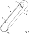
FIG. 2 a perspective view of the protective pipe according to the invention;
FIG. 3 a perspective view of the protective pipe, as well as a hose that surrounds the protective pipe, partly in section.
DESCRIPTION OF AN EXEMPLARY EMBODIMENT
In FIG. 1, a UV lamp 1 is shown. This UV lamp 1 consists of a UV tube 2, which in turn comprises a socket 3 with an electrical connector 4. A UV source is coupled with the socket 3; the source is not shown in any detail in the drawing. The UV source is surrounded by a rod-shaped encasing pipe 5. The encasing pipe 5 generally consists of a quartz glass. The end of the UV tube 2 that lies opposite the socket 3 has an end element 6. A protective pipe 8 having a circumferential surface 7 surrounds the encasing pipe 5. The protective pipe 8 has rotation symmetry and is open at both its end faces. In this way, it is possible to push the protective pipe 8 over the encasing pipe 5. In a preferred exemplary embodiment, which is shown in FIG. 1, the protective pipe 8 has elements 9 on both sides, which each interact with inside threads 10 within the protective pipe 8, so that the UV tube 2 can be firmly positioned within the protective pipe 8. Alternative attachment means for the elements 9 are also conceivable, such as, for example, a magnetic closure, bayonet closure, etc.
The protective pipe 8—as also shown in FIG. 2—furthermore has a viewing window 11. This viewing window 11 extends over a partial region of the circumferential surface 7 of the protective pipe 8. This viewing window 11 gives access to the encasing pipe 5 and has no transparent covering. This brings with it the advantage that the radiation 12 of the UV source, which is emitted out of the encasing pipe 5, is released in the direction shown.
The coating 13 of polytetrafluoroethylene is affixed within the protective pipe 8 and forms a reflector 14. A major portion (approximately 95%) of the radiation emitted from the protective pipe 8 is reflected into the environment by way of the reflector. Because of the very simple processing of polytetrafluoroethylene, the reflector 14 can be shaped to fit the encasing pipe 5. Furthermore, very close contact with the encasing pipe 5 is possible, because a facet-like configuration, as it is known when using aluminum, is eliminated.
In FIG. 3, a perspective view of the protective pipe 8 according to FIG. 2 is shown, but with the difference that this pipe is surrounded by a protective hose 15. This protective hose 15, as it is shown in FIG. 3, surrounds the protective pipe 8 completely and lies closely against its circumferential surface 7. This protective hose 15 extends over the free ends of the protective pipe 8, and is accommodated by the elements 9, together with the corresponding seals. The seals lie closely against the outer wall of the protective hose 15. In this way, the encasing pipe 5 that lies on the inside is completely sealed off. If the UV source is exposed to extreme environmental conditions, dirt also cannot get to the encasing pipe from the outside, since the viewing window 11 is completely covered by the hose 15, which consists of transparent material. The material is selected in such a manner that the emitted radiation 12 is not influenced or is only influenced slightly. Preferably, a transparent Teflon material is proposed, since this is also extremely tear-resistant.
In this way, a protective pipe 8 having a reflector 14 as well as a hose 15 that surrounds the protective pipe 8 is made available, which pipe provides uniform UV radiation quality and power almost independent of the field of use, with reference to the environment, because it was surprisingly found that a constant local environment for the radiation source has a significant influence on the emitted radiation power. Furthermore, such a UV source can also be used in critical areas, for example the foods industry.
REFERENCE SYMBOL LIST
Protective Pipe for a UV Tube, Particularly a UV-C Tube
  • 1 UV lamp
  • 2 tube
  • 3 socket
  • 4 connector
  • 5 encasing pipe
  • 6 end element
  • 7 circumferential surface
  • 8 protective pipe
  • 9 elements
  • 10 inside thread
  • 11 viewing window
  • 12 radiation
  • 13 coating
  • 14 reflector
  • 15 hose

Claims (3)

The invention claimed is:
1. A protective tube for a UV lamp for accommodating a light-emitting device on having a rod-shaped casing tube,
wherein the light-emitting device emits UVC radiation,
wherein the protective tube comprises a circumferential surface and a window extending over a partial region only of the circumferential surface,
wherein radiation emitted by the rod-shaped casing tube can emerge through the window,
wherein a coating composed of polytetrafluoroethylene is applied as a reflector to the inner side of the protective tube,
wherein the protective tube comprises metal, and
wherein the window is surrounded by a hose that comprises plastic and is at least partially transparent, at least in a region of the window, the hose lying directly against the entire circumferential surface of the protective tube.
2. The protective tube according to claim 1, wherein the protective tube comprises stainless steel or aluminum.
3. The protective tube according to claim 1, wherein the hose comprises polytetrafluoroethylene.
US15/561,102 2015-04-09 2016-04-07 Protective pipe for a UV tube, in particular a UV-C tube Active US10857254B2 (en)

Applications Claiming Priority (4)

Application Number Priority Date Filing Date Title
DE102015105362.4A DE102015105362A1 (en) 2015-04-09 2015-04-09 Protective tube for a UV tube, in particular a UVC tube
DE102015105362.4 2015-04-09
DE102015105362 2015-04-09
PCT/IB2016/051967 WO2016162816A1 (en) 2015-04-09 2016-04-07 Protective pipe for a uv tube, in particular a uv-c tube

Publications (2)

Publication Number Publication Date
US20180117208A1 US20180117208A1 (en) 2018-05-03
US10857254B2 true US10857254B2 (en) 2020-12-08

Family

ID=56069173

Family Applications (1)

Application Number Title Priority Date Filing Date
US15/561,102 Active US10857254B2 (en) 2015-04-09 2016-04-07 Protective pipe for a UV tube, in particular a UV-C tube

Country Status (4)

Country Link
US (1) US10857254B2 (en)
EP (1) EP3280951B1 (en)
DE (1) DE102015105362A1 (en)
WO (1) WO2016162816A1 (en)

Cited By (2)

* Cited by examiner, † Cited by third party
Publication number Priority date Publication date Assignee Title
US10980906B2 (en) * 2016-12-30 2021-04-20 Miriah Gilliam-Perkins Device for reducing germs on a writing instrument or stylus
US11511008B2 (en) * 2020-07-01 2022-11-29 H7 Technologies, Inc. Automated robotic system and method for sanitization and disinfection

Families Citing this family (9)

* Cited by examiner, † Cited by third party
Publication number Priority date Publication date Assignee Title
DE102016121481A1 (en) * 2016-11-09 2018-05-09 Osram Gmbh Lamp with control gear and arrangement with air conditioning
KR102827320B1 (en) * 2016-12-16 2025-07-01 엘지전자 주식회사 Water purifying apparatus
DE102017125833B4 (en) 2017-11-06 2023-06-22 Sterilair Ag UV lamp consisting of a UV tube with a rod-shaped cladding tube and a base with electrical connections and a reflector
USD957027S1 (en) * 2020-02-28 2022-07-05 Beijing Xiaomi Mobile Software Co., Ltd. Hanging lamp for a display screen
USD957020S1 (en) * 2020-02-28 2022-07-05 Beijing Xiaomi Mobile Software Co., Ltd. Hanging lamp for a display screen
USD957019S1 (en) * 2020-02-28 2022-07-05 Beijing Xiaomi Mobile Software Co., Ltd. Hanging lamp for a display screen
GB2611062A (en) * 2021-09-24 2023-03-29 Finsen Tech Limited A UV-C room disinfection device
USD1025440S1 (en) * 2022-04-01 2024-04-30 Magnus Long Lamp
USD1099390S1 (en) * 2024-05-28 2025-10-21 Shipeng Liang Floor lamp

Citations (9)

* Cited by examiner, † Cited by third party
Publication number Priority date Publication date Assignee Title
US4048537A (en) 1976-06-04 1977-09-13 Gte Sylvania Incorporated Protective ultraviolet-transmitting sleeve for fluorescent lamp
WO2000001986A1 (en) 1998-07-02 2000-01-13 Alliedsignal Inc. Structure for achieving a linear light source geometry
US6186649B1 (en) * 1998-04-16 2001-02-13 Honeywell International Inc. Linear illumination sources and systems
US6397839B1 (en) 1998-03-04 2002-06-04 Tebro Dispensing device for fluid product activated by inhaling
JP2002237209A (en) 2001-02-09 2002-08-23 Nippon Kooban Kk Sleeve for discharge tube
DE20306737U1 (en) 2003-04-30 2004-09-02 Zumtobel Staff Ges.M.B.H. Light used as a balcony light comprises a longitudinal gas discharge lamp held by a carrier element and surrounded by a cylindrical partially reflective protective tube made from a light-permeable material
US20060113485A1 (en) 2004-11-26 2006-06-01 Marth Ferres Sterilizing lamp
US20080048541A1 (en) * 2004-12-20 2008-02-28 Sumrall Ernest N Polymer-thermal shield for ultra-violet lamp
US20110002058A1 (en) * 2009-07-01 2011-01-06 Darrin Leonhardt Spread reflector for a lamp structure

Family Cites Families (4)

* Cited by examiner, † Cited by third party
Publication number Priority date Publication date Assignee Title
US5103385A (en) * 1990-07-27 1992-04-07 Eastman Kodak Company Linear light source
US5905594A (en) * 1995-01-06 1999-05-18 W. L. Gore & Associates, Inc. Light reflectant surface in a recessed cavity substantially surrounding a compact fluorescent lamp
JPWO2011030856A1 (en) * 2009-09-11 2013-02-07 株式会社オプトデザイン Surface illumination method using point light source, linear light source device, and surface illumination device using this linear light source device
CN103518097B (en) * 2011-04-07 2016-03-30 3M创新有限公司 Decorative lights

Patent Citations (10)

* Cited by examiner, † Cited by third party
Publication number Priority date Publication date Assignee Title
US4048537A (en) 1976-06-04 1977-09-13 Gte Sylvania Incorporated Protective ultraviolet-transmitting sleeve for fluorescent lamp
US6397839B1 (en) 1998-03-04 2002-06-04 Tebro Dispensing device for fluid product activated by inhaling
DE69912253T2 (en) 1998-03-04 2004-08-12 Tebro INHALATION ACTUATED DISPENSER FOR A LIQUID PRODUCT
US6186649B1 (en) * 1998-04-16 2001-02-13 Honeywell International Inc. Linear illumination sources and systems
WO2000001986A1 (en) 1998-07-02 2000-01-13 Alliedsignal Inc. Structure for achieving a linear light source geometry
JP2002237209A (en) 2001-02-09 2002-08-23 Nippon Kooban Kk Sleeve for discharge tube
DE20306737U1 (en) 2003-04-30 2004-09-02 Zumtobel Staff Ges.M.B.H. Light used as a balcony light comprises a longitudinal gas discharge lamp held by a carrier element and surrounded by a cylindrical partially reflective protective tube made from a light-permeable material
US20060113485A1 (en) 2004-11-26 2006-06-01 Marth Ferres Sterilizing lamp
US20080048541A1 (en) * 2004-12-20 2008-02-28 Sumrall Ernest N Polymer-thermal shield for ultra-violet lamp
US20110002058A1 (en) * 2009-07-01 2011-01-06 Darrin Leonhardt Spread reflector for a lamp structure

Non-Patent Citations (1)

* Cited by examiner, † Cited by third party
Title
International Search Report of PCT/IB2016/051967, dated Jul. 13, 2016.

Cited By (2)

* Cited by examiner, † Cited by third party
Publication number Priority date Publication date Assignee Title
US10980906B2 (en) * 2016-12-30 2021-04-20 Miriah Gilliam-Perkins Device for reducing germs on a writing instrument or stylus
US11511008B2 (en) * 2020-07-01 2022-11-29 H7 Technologies, Inc. Automated robotic system and method for sanitization and disinfection

Also Published As

Publication number Publication date
EP3280951B1 (en) 2019-06-12
WO2016162816A1 (en) 2016-10-13
DE102015105362A1 (en) 2016-10-13
US20180117208A1 (en) 2018-05-03
EP3280951A1 (en) 2018-02-14

Similar Documents

Publication Publication Date Title
US10857254B2 (en) Protective pipe for a UV tube, in particular a UV-C tube
JP6994687B2 (en) Fluid sterilizer
US6767453B2 (en) Portable water purifier with ultraviolet light source
CN103025665B (en) A device for subjecting fluids to disinfection by exposing them to ultraviolet light
JP6374403B2 (en) Method and apparatus for liquid disinfection with light emitted from light emitting diodes
CN102807264B (en) The liquid purification and treatment device of double-sleeve structure
JP6994688B2 (en) Fluid sterilizer
KR20150080489A (en) Ultraviolet sterilizer and sterilization method
TW201922298A (en) Sterilization device, sterilization method, and staphylococcus aureus sterilization method
JP2023078423A (en) Fluid sterilizer
US20210047205A1 (en) Ultraviolet sterilization tube and ultraviolet sterilization device
EP4147726B1 (en) Ultraviolet sterilization device
US6570173B1 (en) Device for disinfecting water flowing through a sanitary facility
CN117460921A (en) Light-emitting device with adjustable sensitivity and curing device using the light-emitting device
JP2017047385A (en) Sterilizer
KR102585542B1 (en) Light irradiation device
EP1975976A1 (en) Low-pressure mercury vapour discharge lamp for disinfecting a medium
CN111170404B (en) A flow-through sterilization device
JP5292598B2 (en) Low pressure mercury lamp and sterilization or disinfection method
EP4460338B1 (en) A radiation generating system comprising an optical arrangement for a far uv light source minimizing the impact of unfiltered undesired wavelengths
CN219991229U (en) Fluid treatment device
TWM515341U (en) Chopsticks storage box
CN216106125U (en) Ultraviolet sterilization device
JP2021079344A (en) Ultraviolet irradiation device
WO2022148746A1 (en) A light emitting device

Legal Events

Date Code Title Description
AS Assignment

Owner name: STERILAIR AG, SWITZERLAND

Free format text: ASSIGNMENT OF ASSIGNORS INTEREST;ASSIGNORS:GRAUPNER, MARTIN;SCHLEGEL, SIMON;REEL/FRAME:043678/0325

Effective date: 20170921

FEPP Fee payment procedure

Free format text: ENTITY STATUS SET TO UNDISCOUNTED (ORIGINAL EVENT CODE: BIG.); ENTITY STATUS OF PATENT OWNER: SMALL ENTITY

FEPP Fee payment procedure

Free format text: ENTITY STATUS SET TO SMALL (ORIGINAL EVENT CODE: SMAL); ENTITY STATUS OF PATENT OWNER: SMALL ENTITY

STPP Information on status: patent application and granting procedure in general

Free format text: NON FINAL ACTION MAILED

STPP Information on status: patent application and granting procedure in general

Free format text: RESPONSE TO NON-FINAL OFFICE ACTION ENTERED AND FORWARDED TO EXAMINER

STPP Information on status: patent application and granting procedure in general

Free format text: FINAL REJECTION MAILED

STPP Information on status: patent application and granting procedure in general

Free format text: NON FINAL ACTION MAILED

STPP Information on status: patent application and granting procedure in general

Free format text: RESPONSE TO NON-FINAL OFFICE ACTION ENTERED AND FORWARDED TO EXAMINER

STCF Information on status: patent grant

Free format text: PATENTED CASE

MAFP Maintenance fee payment

Free format text: PAYMENT OF MAINTENANCE FEE, 4TH YR, SMALL ENTITY (ORIGINAL EVENT CODE: M2551); ENTITY STATUS OF PATENT OWNER: SMALL ENTITY

Year of fee payment: 4