US108564A - Improvement in links for endless-chain horse-powers - Google Patents
Improvement in links for endless-chain horse-powers Download PDFInfo
- Publication number
- US108564A US108564A US108564DA US108564A US 108564 A US108564 A US 108564A US 108564D A US108564D A US 108564DA US 108564 A US108564 A US 108564A
- Authority
- US
- United States
- Prior art keywords
- link
- axle
- bolt
- links
- chain
- Prior art date
- Legal status (The legal status is an assumption and is not a legal conclusion. Google has not performed a legal analysis and makes no representation as to the accuracy of the status listed.)
- Expired - Lifetime
Links
- CWYNVVGOOAEACU-UHFFFAOYSA-N Fe2+ Chemical compound [Fe+2] CWYNVVGOOAEACU-UHFFFAOYSA-N 0.000 description 3
- 229910000754 Wrought iron Inorganic materials 0.000 description 3
- 238000010276 construction Methods 0.000 description 3
- 230000001788 irregular Effects 0.000 description 3
- 210000001503 joint Anatomy 0.000 description 3
- 241000239290 Araneae Species 0.000 description 1
- 229910001018 Cast iron Inorganic materials 0.000 description 1
- 206010023230 Joint stiffness Diseases 0.000 description 1
- 102100023170 Nuclear receptor subfamily 1 group D member 1 Human genes 0.000 description 1
- 229910000831 Steel Inorganic materials 0.000 description 1
- 238000005266 casting Methods 0.000 description 1
- 210000005069 ears Anatomy 0.000 description 1
- 210000002837 heart atrium Anatomy 0.000 description 1
- 239000010959 steel Substances 0.000 description 1
Images
Classifications
-
- A—HUMAN NECESSITIES
- A63—SPORTS; GAMES; AMUSEMENTS
- A63B—APPARATUS FOR PHYSICAL TRAINING, GYMNASTICS, SWIMMING, CLIMBING, OR FENCING; BALL GAMES; TRAINING EQUIPMENT
- A63B22/00—Exercising apparatus specially adapted for conditioning the cardio-vascular system, for training agility or co-ordination of movements
- A63B22/0015—Exercising apparatus specially adapted for conditioning the cardio-vascular system, for training agility or co-ordination of movements with an adjustable movement path of the support elements
- A63B22/0023—Exercising apparatus specially adapted for conditioning the cardio-vascular system, for training agility or co-ordination of movements with an adjustable movement path of the support elements the inclination of the main axis of the movement path being adjustable, e.g. the inclination of an endless band
Definitions
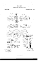
- Figure l is a top view of the face of the link, showing the end of the link upon which the supportingwheelis placed.
- Figure 2 represents the connecting end of the.link, the wheel end of which is shown in fig. 1.
- Figure 31 s a side view of the same end of the link as shown in fig. 1.
- Figure 4 is a side view of the same end of the link as shown in'fig. 2.
- Figure 5 is a side view oi' two links connected together, with treads and wheel attached.
- Figure (5 is a longitudinal section of the wheel end of the link, showing the form of the recess 1 when the stud H, in fi 7, is made to till the recess without any removable box.
- Figure 7 is a side view of the connecting end of the link shown in fig. 6.
- Figure 8 is a longitudinal section, showing same parts as ti". 6 when the link is formed with a recess to receive an auxiliary pivot-seat, K, in the recess J.
- Figures 9 and 1.0 are face and side views of'thc removable box or pivot-seat- K.
- Figure 11 is an end view of the baseof the wheelaxle.
- Figure 12 is a lo -igitudinal section through the center of the wheel-axle.
- Figure 13 is a view of the outer end of the wheelaxle.
- Figure 14 is a view of the supporting-wheel.
- FIG. 15 is a view of the pivot-connecting bolt.
- Figure 16 is washer used under the head of pivotbolt.
- Figure 17 is asat'ety-nut which holds all the pivoted connect-ions securely together.
- my invention consists in so constructing and arranging the parts of the moving platform that, when complete, the attachment of the supporting-trucks is so secured that neither the bolt or nut or their equivalent can be acted upon by the jar or vibration or the chain so as to allow the truck to come off.
- This improvement is applicable to endless-chain powers ot'common construction, either employing reels, spiders, or rack and pinion.
- A is a link provided with cogs.
- O is an axle which may be cast directly ontothe link or made separate, and is constructed with a hole extending entirely through its length.
- this hollow tube or axle should be made square to fit the bolt g, which should also be square under its head, but any irregular form will answer that will hold the bolt from turning in the axle.
- the base of the axle should be enlarged, as shown in fig. 1, forming a flange in which is the square or an irregular formed-seat, c.
- This seat should fit a projection or boss, 0, on the link A, (see fig. 3,) of any desirable form to hold the axle from turning on the link A, or the axle C may be cast rigidly onto the link.
- the link A is constructed at this end with two cars, .1: .2, upon which is projected the brace E.
- the outer or square end of the bolt 9 should be provided with awasher, d, fitted against its head.
- the wheel ⁇ V should be placed upon the axle C, the links A A placed in position to connectwith each other, and the round part of the bolt passed into the .holes h 71, made to receive it, (see 1 and 3.)
- the nut f is then screwed down onto the link A and turned square with the link,
- the wood-tread 1% is provided with holes for the boss D and bolt in.
- the tread B is placed in position on the link, thc
- boss 1) in its seat, the hole in. the tread directlyover the hole in the ear 1", and, thc'bolt m ispasscd into position, the thread-nut n screwed down, and, by means of the boss 1) and its-seat in thc'tread, in connection with the bolt in, the link and tread are firmly held together.
- bosses are provided with boxes K K, (see figs. 9 and 10,) and fit int-0' seats J, (see fig. 8;) or they may be constructed without the use of the boxes K K; but in this case thebearings would not be as perfect, and in this case the recess would be lllZLdGOf the same'size as the boss H, as shown in figs. 6 and T.
- the wrought-iron boltand nut- (which pass through i the axle and link connections) should be casc-hardenml.
- the tread B is held in position by the bolt in.
- the cars a a1 project beyond the connecting-bolt 5/.
- the seat 1', fig. (hula-y be constructed on the upper side of theea-rsar x, or in the manner shown by I in fig.
- the wheel ⁇ V is placed on the axle O, the connecting end of the link A is placed in position between the flanges a; a the bolt 91 is passed through its seat in the axle and through both links, the nut f is screwed down firmly, and the nutand bolt hold the wheel on, and the axle and wheel firmly together.
- the nntf is of suflicient size to form an even plane sition with the boss 1) in its seat, and all the parts are hcldfirmly together by the bolt g, as the tread Ii rests directly on the edge of the nut so thatit cannot be turned either on or off without 'rst removing the tread.
- the bolt and axle also archeld by the form of the bolt and the form of the axle, the seat in the base ofthe axle preventing it from turning either forward or back, and the square under the head of the bolt preventing that also from turning.
- the vibration or jar caused by running the machine cannot have any cfiect to turn either the belt or nut, and the axle and wheel remain always firmly attached to the chain.
- the bosses H H extend into the cars a; it.
- This device lengthens the wearing surface of the connectbig or central part of the link, and as the bolt g, which connects the links, is fixed stationary in the ears x'x, 'the'link turns on the central portion of the bosses H ll, and also takes a bearing on their outer surtiice in wearing suit'acc.
- a three-fold wearing surface is obtained having all the advantages of chilled castiron surface for wear, with all the strength of a casehardened wrought-iron for connections.
- the brace 1* provided with a boss, D, in combination with a horse-power tread and link, constructed and arranged substantially as described.
- the tread B is placed inpothe boxes K K, making a double and a three-fold u.
Landscapes
- Health & Medical Sciences (AREA)
- Cardiology (AREA)
- Vascular Medicine (AREA)
- General Health & Medical Sciences (AREA)
- Physical Education & Sports Medicine (AREA)
- Escalators And Moving Walkways (AREA)
Description
e E. BURT. Endless Chain Horse Power Link.
No. 108,564. Patented Oct. 25, 1870.
HHUHHUn \lllllll Wmesses cum-n1 glitches atria Gtfltha.
Letters Patent Nc. 108,564, dated October 25, 1870.
IMPROVEMENT lN LINKS FOR ENDLESS-CHAIN HORSE-POWERS.
The Schedule referred to in these Letters Patent and making pant of the same.
Be it known that I, GEORGE E. BURT, of Harvard, in the county of \Vorcestcr, in the State of Massachusetts, have invented a new and improved Link for Endless-Chain Horse-Powers; and I do hereby declare that the following is a full and exact description thereof, reference being had to the accompanying drawing and to the letters of reference marked thereon.
Like letters represent like parts in all the figures.
Description offllc Accompanying Drawing.
Figure l is a top view of the face of the link, showing the end of the link upon which the supportingwheelis placed.-
In this and the other figures one end of the link is broken away to allow a large scale to be used to show the parts clearly.
Figure 2 represents the connecting end of the.link, the wheel end of which is shown in fig. 1. I
Figure 31s a side view of the same end of the link as shown in fig. 1.
Figure 4 is a side view of the same end of the link as shown in'fig. 2.
Figure 5 is a side view oi' two links connected together, with treads and wheel attached.
Figure (5 is a longitudinal section of the wheel end of the link, showing the form of the recess 1 when the stud H, in fi 7, is made to till the recess without any removable box.
Figure 7 is a side view of the connecting end of the link shown in fig. 6. I V
Figure 8 is a longitudinal section, showing same parts as ti". 6 when the link is formed with a recess to receive an auxiliary pivot-seat, K, in the recess J.
Figures 9 and 1.0 are face and side views of'thc removable box or pivot-seat- K.
Figure 11 is an end view of the baseof the wheelaxle.
Figure 12 is a lo -igitudinal section through the center of the wheel-axle.
Figure 13 is a view of the outer end of the wheelaxle.
Figure 14 is a view of the supporting-wheel.
\ Figure 15 is a view of the pivot-connecting bolt.
Figure 16 is washer used under the head of pivotbolt.
Figure 17 is asat'ety-nut which holds all the pivoted connect-ions securely together.
It is well known to manufitcturcrs and users of endless-chain horse-powers that-the supporting-wheels of the moving platform or chain are very liable to come cit and cause breakage.
Nuts and set-screws have been employed, but the continued vibration caused by the heavy jar and the continued reversion of motion of the trucks in passing from the upper to the lower track in a short time causes the nuts or screws to unscrew and work oft.
Stationary guides have been used to avoid this difficulty, but such guides soon become worn, and the friction caused by them makes quite a loss in the per cent. of power.
There is also a diiiiculty in chain powers caused by the wearing away of the connect-ions of the links, particularly when a rack and pinion are employed to transmit the power to the driving-wheel. It will readily be seen that by the wearing away of the connecting-pivots and the enlargement of their seats the pitch of the end cogs is increased, thus causing more friction on the pinion as these joints of the chain pass it, and in a short time the difference of pitch would be so great that the cogs would not mesh into each other at this point, thus causing a breakage in the gearing.
To entirely overcome this first diliiculty, and in a great measure obviate the second, are the objects of my invention.
The nature of my invention consists in so constructing and arranging the parts of the moving platform that, when complete, the attachment of the supporting-trucks is so secured that neither the bolt or nut or their equivalent can be acted upon by the jar or vibration or the chain so as to allow the truck to come off. H
Also, in so constructing and arranging the connections of the flexible joints to horse-power chains as to greatly increase their durability.
To enable others skilled in the art to make and use my invention, I will proceed to describe its construction and operation.
This improvement is applicable to endless-chain powers ot'common construction, either employing reels, spiders, or rack and pinion. A is a link provided with cogs.
O is an axle which may be cast directly ontothe link or made separate, and is constructed with a hole extending entirely through its length.
The outer end of this hollow tube or axle should be made square to fit the bolt g, which should also be square under its head, but any irregular form will answer that will hold the bolt from turning in the axle.
The base of the axle should be enlarged, as shown in fig. 1, forming a flange in which is the square or an irregular formed-seat, c.
This seat should fit a projection or boss, 0, on the link A, (see fig. 3,) of any desirable form to hold the axle from turning on the link A, or the axle C may be cast rigidly onto the link.
The link A is constructed at this end with two cars, .1: .2, upon which is projected the brace E.
as shown.
'in its place on the link its upper edge should be even or form a plane withthe top of the link.
The outer or square end of the bolt 9 should be provided with awasher, d, fitted against its head.
The wheel \V should be placed upon the axle C, the links A A placed in position to connectwith each other, and the round part of the bolt passed into the .holes h 71, made to receive it, (see 1 and 3.)
The nut f is then screwed down onto the link A and turned square with the link,
The wood-tread 1% is provided with holes for the boss D and bolt in.
The tread B is placed in position on the link, thc
boss 1) in its seat, the hole in. the tread directlyover the hole in the ear 1", and, thc'bolt m ispasscd into position, the thread-nut n screwed down, and, by means of the boss 1) and its-seat in thc'tread, in connection with the bolt in, the link and tread are firmly held together.
It will be seen that the nut j' cannot be turned at all without first removing the tread from the link, and
the vibration and jar caused by running the chain canha've no efi'cct to turn off/the nntj'.
I construct the chain-links with the end forming the central section to fit between the cars a, which are constructed with seats 3' J, opening from the lower side, (see fig. 8.)
The central sect-ion .l. construct with bosses H H.
These bosses are provided with boxes K K, (see figs. 9 and 10,) and fit int-0' seats J, (see fig. 8;) or they may be constructed without the use of the boxes K K; but in this case thebearings would not be as perfect, and in this case the recess would be lllZLdGOf the same'size as the boss H, as shown in figs. 6 and T.
\Vhen the links are connected the bolts 1 pass through the boxes and all the sections connecting the links, and hold the axle and wheel all in position,
The boxes and seats, axle and wheel are cast on chills, making a. cheap but verydurahlc. wearing-surface.
The wrought-iron boltand nut- (which pass through i the axle and link connections) should be casc-hardenml.
The tread B is held in position by the bolt in.
The cars a a1 project beyond the connecting-bolt 5/.
and the brace 1) connecting them thus, makes a stiff joint *on the upper side of the chain, but perfectly flexible, to bend in the opposite direction. This is desirablc,-as it makes iteasy to handle when making or rcpairing.
b, fig. 3, shows-the flange which forms a rest for the axle, to hold it firmly in place when itis east separate from the link.
The seat 1', fig. (hula-y be constructed on the upper side of theea-rsar x, or in the manner shown by I in fig.
6,1he open portion of the seat being curved the form of the chill used in casting the seat. I I The seats or rests for the projections H 11 are of a half-circle and fit the projections 11 on the working side, thus makinga good working-bearing for the connections.
Operation.
The wheel \V is placed on the axle O, the connecting end of the link A is placed in position between the flanges a; a the bolt 91 is passed through its seat in the axle and through both links, the nut f is screwed down firmly, and the nutand bolt hold the wheel on, and the axle and wheel firmly together.
- The nntf is of suflicient size to form an even plane sition with the boss 1) in its seat, and all the parts are hcldfirmly together by the bolt g, as the tread Ii rests directly on the edge of the nut so thatit cannot be turned either on or off without 'rst removing the tread. The bolt and axlealso archeld by the form of the bolt and the form of the axle, the seat in the base ofthe axle preventing it from turning either forward or back, and the square under the head of the bolt preventing that also from turning. Thus the vibration or jar caused by running the machine cannot have any cfiect to turn either the belt or nut, and the axle and wheel remain always firmly attached to the chain.
The bosses H H extend into the cars a; it. This device lengthens the wearing surface of the connectbig or central part of the link, and as the bolt g, which connects the links, is fixed stationary in the ears x'x, 'the'link turns on the central portion of the bosses H ll, and also takes a bearing on their outer surtiice in wearing suit'acc. Thus a three-fold wearing surface is obtained having all the advantages of chilled castiron surface for wear, with all the strength of a casehardened wrought-iron for connections. By this arrangement the durability of the joints will be greatly increased;
Having thus described the construction and operation of my invention,
\Vhat- [claim as new, and desire to secure by Letters Patent, isv p 1. The wheelV, in-an endless-chain horse-power when held in position on the link A by means of a boltso arranged thatit cannotbe unscrewed without first removing the tread from the link, substantially as described, and for the purpose set forth.
2. The brace 1*), provided with a boss, D, in combination with a horse-power tread and link, constructed and arranged substantially as described.
bolt y, and wheel \\',-arranged substantially as de scribed, for the purpose set forth.
4. The flange b, in combination with axle O and link A, to hold the axle in position, substantially as set forth. l p
5. Thohui'; fand bolt g, or their mechanical equivalents, when arranged and held in position. by the tread B, substantiallyas described, for the purpose set forth.
6. The double pivoted connection for the links, a hollow axle having a square or irregular chamber, and bosses, all held in position by a wrought-iron or steel bolt, so constructed and arranged that the tread, when fixed to the link, will hold the nut of said boltposit-ively in place. 7
Witnesses: I GEORGE E. BURT.
[12.15. Boar, 'A. Bear.
with the top of the link, the tread B is placed inpothe boxes K K, making a double and a three-fold u. The seat 0', in combination with the axle G, the
Publications (1)
| Publication Number | Publication Date |
|---|---|
| US108564A true US108564A (en) | 1870-10-25 |
Family
ID=2178038
Family Applications (1)
| Application Number | Title | Priority Date | Filing Date |
|---|---|---|---|
| US108564D Expired - Lifetime US108564A (en) | Improvement in links for endless-chain horse-powers |
Country Status (1)
| Country | Link |
|---|---|
| US (1) | US108564A (en) |
-
0
- US US108564D patent/US108564A/en not_active Expired - Lifetime
Similar Documents
| Publication | Publication Date | Title |
|---|---|---|
| US590649A (en) | Sprocket wheel and chain | |
| US108564A (en) | Improvement in links for endless-chain horse-powers | |
| US623431A (en) | Drive-chain and chain-wheel | |
| US535851A (en) | Sleigh-knee | |
| US598014A (en) | Power-transmitter | |
| US122850A (en) | Improvement in land-carriages | |
| US711991A (en) | Gear-wheel. | |
| US639575A (en) | Bicycle-chain. | |
| US694870A (en) | Drive-chain. | |
| US492550A (en) | Thirds to andrew krouse and george krotjse | |
| US570698A (en) | Frederic a | |
| US633470A (en) | Driving-gear. | |
| US135235A (en) | William b | |
| US283751A (en) | Chain-link | |
| US581024A (en) | Sprocket mechanism for bigycles | |
| US568837A (en) | Sprocket-wheel | |
| US566995A (en) | Adjustable drag-chain | |
| US163832A (en) | Improvement in chains and wheels for transmitting power | |
| US580369A (en) | John d | |
| US272869A (en) | Self-lubricating bearing | |
| US1186721A (en) | Endless-track structure for tractors. | |
| US266699A (en) | Belt-gearing | |
| US313467A (en) | Assigkob to the | |
| US948385A (en) | Sprocket-wheel. | |
| US455226A (en) | Half to charles a |