US10853378B1 - Electronic note management via a connected entity graph - Google Patents
Electronic note management via a connected entity graph Download PDFInfo
- Publication number
- US10853378B1 US10853378B1 US14/856,548 US201514856548A US10853378B1 US 10853378 B1 US10853378 B1 US 10853378B1 US 201514856548 A US201514856548 A US 201514856548A US 10853378 B1 US10853378 B1 US 10853378B1
- Authority
- US
- United States
- Prior art keywords
- entity
- type
- graph
- entities
- target
- Prior art date
- Legal status (The legal status is an assumption and is not a legal conclusion. Google has not performed a legal analysis and makes no representation as to the accuracy of the status listed.)
- Active, expires
Links
Images


Classifications
-
- G—PHYSICS
- G06—COMPUTING; CALCULATING OR COUNTING
- G06F—ELECTRIC DIGITAL DATA PROCESSING
- G06F16/00—Information retrieval; Database structures therefor; File system structures therefor
- G06F16/20—Information retrieval; Database structures therefor; File system structures therefor of structured data, e.g. relational data
- G06F16/24—Querying
- G06F16/248—Presentation of query results
-
- G—PHYSICS
- G06—COMPUTING; CALCULATING OR COUNTING
- G06F—ELECTRIC DIGITAL DATA PROCESSING
- G06F3/00—Input arrangements for transferring data to be processed into a form capable of being handled by the computer; Output arrangements for transferring data from processing unit to output unit, e.g. interface arrangements
- G06F3/01—Input arrangements or combined input and output arrangements for interaction between user and computer
- G06F3/048—Interaction techniques based on graphical user interfaces [GUI]
- G06F3/0484—Interaction techniques based on graphical user interfaces [GUI] for the control of specific functions or operations, e.g. selecting or manipulating an object, an image or a displayed text element, setting a parameter value or selecting a range
- G06F3/04847—Interaction techniques to control parameter settings, e.g. interaction with sliders or dials
-
- G—PHYSICS
- G06—COMPUTING; CALCULATING OR COUNTING
- G06F—ELECTRIC DIGITAL DATA PROCESSING
- G06F16/00—Information retrieval; Database structures therefor; File system structures therefor
- G06F16/20—Information retrieval; Database structures therefor; File system structures therefor of structured data, e.g. relational data
- G06F16/22—Indexing; Data structures therefor; Storage structures
- G06F16/2291—User-Defined Types; Storage management thereof
-
- G—PHYSICS
- G06—COMPUTING; CALCULATING OR COUNTING
- G06F—ELECTRIC DIGITAL DATA PROCESSING
- G06F16/00—Information retrieval; Database structures therefor; File system structures therefor
- G06F16/20—Information retrieval; Database structures therefor; File system structures therefor of structured data, e.g. relational data
- G06F16/24—Querying
- G06F16/245—Query processing
- G06F16/2457—Query processing with adaptation to user needs
- G06F16/24575—Query processing with adaptation to user needs using context
-
- G—PHYSICS
- G06—COMPUTING; CALCULATING OR COUNTING
- G06F—ELECTRIC DIGITAL DATA PROCESSING
- G06F16/00—Information retrieval; Database structures therefor; File system structures therefor
- G06F16/20—Information retrieval; Database structures therefor; File system structures therefor of structured data, e.g. relational data
- G06F16/24—Querying
- G06F16/245—Query processing
- G06F16/2458—Special types of queries, e.g. statistical queries, fuzzy queries or distributed queries
-
- G—PHYSICS
- G06—COMPUTING; CALCULATING OR COUNTING
- G06F—ELECTRIC DIGITAL DATA PROCESSING
- G06F16/00—Information retrieval; Database structures therefor; File system structures therefor
- G06F16/90—Details of database functions independent of the retrieved data types
- G06F16/901—Indexing; Data structures therefor; Storage structures
- G06F16/9024—Graphs; Linked lists
-
- G—PHYSICS
- G06—COMPUTING; CALCULATING OR COUNTING
- G06F—ELECTRIC DIGITAL DATA PROCESSING
- G06F16/00—Information retrieval; Database structures therefor; File system structures therefor
- G06F16/90—Details of database functions independent of the retrieved data types
- G06F16/95—Retrieval from the web
- G06F16/953—Querying, e.g. by the use of web search engines
- G06F16/9535—Search customisation based on user profiles and personalisation
-
- G—PHYSICS
- G06—COMPUTING; CALCULATING OR COUNTING
- G06F—ELECTRIC DIGITAL DATA PROCESSING
- G06F3/00—Input arrangements for transferring data to be processed into a form capable of being handled by the computer; Output arrangements for transferring data from processing unit to output unit, e.g. interface arrangements
- G06F3/01—Input arrangements or combined input and output arrangements for interaction between user and computer
- G06F3/048—Interaction techniques based on graphical user interfaces [GUI]
- G06F3/0484—Interaction techniques based on graphical user interfaces [GUI] for the control of specific functions or operations, e.g. selecting or manipulating an object, an image or a displayed text element, setting a parameter value or selecting a range
- G06F3/04842—Selection of displayed objects or displayed text elements
Definitions
- the subject innovations relate generally to electronic notes, and more particularly, to electronic note management systems with methodologies for organizing, accessing, and searching electronic notes.
- Computers are very powerful tools for organizing, accessing, and searching information.
- One type of information that computers are useful for organizing, accessing, and searching is electronic text notes (or just “electronic notes”).
- Electronic notes include brief electronic recordings as text of facts, topics, or thoughts, recorded as an aid to memory or for subsequent recall, and short informal letters or messages recorded as text data in a computer.
- Electronic note management systems are a common mechanism for rapidly creating electronic notes on computer systems while providing easy access to users.
- a typical electronic note management system organizes electronic notes in “records” having “fields” of information about the electronic notes.
- an electronic note management system may have a record for each electronic note created by users of the system where each such record contains the text of the electronic note, an identifier of the user that created the note, a timestamp indicating when the user created the note, and one or more text “tags” that organize the note into one or more, possibly user-defined, categories such as, for example, “work,” “home,” “school,” “recipes ideas,” “meeting minutes,” “tv shows to watch,” “books to read,” etc.
- Existing electronic note management systems allow users to keyword search for electronic notes by various text properties of the electronic note records such as the text content and tag(s). Such systems can be effective for locating electronic notes that the searching user knows to exist a priori of the keyword search. For example, existing electronic note management systems can be effective in searching for and locating an electronic note that the searching user remembers previously creating and tagging.
- One limitation of existing electronic note management systems is their limited ability to discover connections and relationships between electronic notes and other non-electronic note entities such as persons, places, things, and events that are related to the electronic notes in some way. For example, with existing electronic systems, it can be inefficient, cumbersome, and frustrating for a searching user to keyword search for and locate electronic notes that are not tagged with a keyword that matches a keyword of the search query. For example, an electronic note representing the minutes of a meeting may be tagged with the date and time and description of the meeting. However, the searching user may know only that a person named Alice attended the meeting but not know when the meeting occurred or the title or subject of meeting. In this case, keyword searching for “Alice” may not produce the electronic note as a search result unless the keyword “Alice” is part of the text content of the electronic note or the electronic note is tagged with the keyword “Alice”.
- the solution should allow a user to use a computer system to discover electronic notes through established relationships the notes have with other electronic notes or with non-electronic note entities such as persons, places, things, and events independent of whether the electronic notes are tagged with search query keywords, thereby improving the use and operation of the computer system.
- the subject innovations provide a solution for these and other needs.
- FIG. 1 is a very general block diagram of a computing device in which software-implemented processes of the subject innovations may be embodied.
- FIG. 2 is a block diagram of a basic software system for controlling the operation of the computing device.
- FIG. 3 is a block diagram of a networked computing environment in which the subject innovations are implemented in some embodiments.
- FIG. 4 depicts an entity-centric data model for data modeling a connected entity graph in a database system according to some embodiments of the subject innovations.
- FIGS. 5A-5C provide example connected entity graphs modeled according to the entity-centric data model.
- FIG. 6A illustrates a graphical user interface providing a note to note first degree connections view of the connected entity graph of FIG. 5C , according to some embodiments of the subject innovations.
- FIG. 6B illustrates a graphical user interface providing a note to note first and second degree connections view of the connected entity graph of FIG. 5C , according to some embodiments of the subject innovations.
- FIG. 7A illustrates a graphical user interface providing a note to object first degree connections view of the connected entity graph of FIG. 5C , according to some embodiments of the subject innovations.
- FIG. 7B illustrates a graphical user interface providing a note to object first and second degree connections view of the connected entity graph of FIG. 5C , according to some embodiments of the subject innovations.
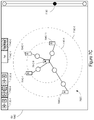
- FIG. 7C illustrates a graphical user interface providing a note to object first and second degree connections view of the connected entity graph of FIG. 5C , according to some embodiments of the subject innovations.
- FIG. 8A illustrates a graphical user interface providing a note to event first degree connections view of the connected entity graph of FIG. 5C , according to some embodiments of the subject innovations.
- FIG. 8B illustrates a graphical user interface providing a note to event first and second degree connections view of the connected entity graph of FIG. 5C , according to some embodiments of the subject innovations.
- FIG. 8C illustrates a graphical user interface providing a note to event first and second degree connections view of the connected entity graph of FIG. 5C , according to some embodiments of the subject innovations
- FIGS. 9A-9H illustrates graphical user interfaces of a visual search around feature, according to some embodiments of the subject innovations.
- FIG. 10 is a flowchart of a method of operation for searching for electronic notes via a connected entity graph, according to some embodiments of the subject innovations.
- FIG. 11 illustrates a graphical user interface providing an all entities view of the connected entity graph of FIG. 5C , according to some embodiments of the subject innovations.
- the subject innovations encompass systems, methods, and computer program code for using an electronic note management system for organizing, accessing, and searching electronic notes via a connected entity graph.
- the electronic note management system can be used to create the connected entity graph comprising electronic note entities and non-electronic note entities (e.g., persons, places, things, and events related to the electronic notes) and relationships between the entities.
- non-electronic note entities e.g., persons, places, things, and events related to the electronic notes
- the electronic note management system can be used to create the connected entity graph comprising a “project” entity, one or more “person” entities that each have a “working on” relationship with the “project” entity, and one or more electronic notes entities each having a “created by” relationship with one of the “person” entities.
- the electronic node management system can be used to create the connected entity graph comprising relationships between electronic note entities in the graph.
- the electronic note management system can be used to create the connected entity graph comprising a “followed up by” relationship between a first electronic note having the “created by” relationship with a “person” entity and a second electronic note also having the “created by” relationship with the “person” entity.
- the electronic note management system can be used to create the connected entity graph comprising different types of entities, including different types of electronic note entities and different types of non-electronic note entities, and different relationships connecting the different entities in the graph.
- users are provided better data modeling options for representing real-world relationships between electronic notes and other electronic notes and between electronic notes and real world entities such as persons, places, things, and events related to the electronic notes in some way.
- connected entity graph visual explorer systems, methods, and computer program code are provided for exploring relationships, developing networks, and uncovering connections involving electronic notes including providing organizational capabilities such as altering visual layout of the connected entity graph and merging entities in the graph into groups.
- the visual graph comprises nodes and edges connecting the nodes.
- the nodes in the visual graph represent entities of the connected entity graph.
- the edges connecting the nodes represent logical relationships that exist between the entities represented by the nodes in the connected entity graph.
- electronic note visual search around systems, methods, and computer-program code are provided for visually searching for electronic notes in the connected entity graph which include choosing a starting entity in the connected entity graph and defining various linking and target parameters that customize the search.
- the result of the search is presented as a visual graph representation of entities and the relationships connecting them.
- the connected entity graph visual explorer provides the user a multitude of features for customizing a visual graph display to best suit the user's needs and maximize efficiency while at the same time serving as an access point for network exploration and pattern discovery features such as the visual search around feature
- the visual search around feature allows the user to define precise parameters to be used to explore the connected entity graph, including which entities should be used as linking parameters and which as targets of the search and how deep into the connected entity graph the search should delve.
- FIG. 1 it is a block diagram that illustrates a basic computing device 100 in which software-implemented processes of the subject innovations may be embodied.
- Computing device 100 and its components, including their connections, relationships, and functions, is meant to be exemplary only, and not meant to limit implementations of the subject innovations.
- Other computing devices suitable for implementing the subject innovations may have different components, including components with different connections, relationships, and functions.
- Computing device 100 may include a bus 102 or other communication mechanism for addressing main memory 106 and for transferring data between and among the various components of device 100 .
- Computing device 100 may also include one or more hardware processors 104 coupled with bus 102 for processing information.
- a hardware processor 104 may be a general purpose microprocessor, a system on a chip (SoC), or other processor suitable for implementing the subject innovations.
- SoC system on a chip
- Main memory 106 such as a random access memory (RAM) or other dynamic storage device, also may be coupled to bus 102 for storing information and instructions to be executed by processor(s) 104 .
- Main memory 106 also may be used for storing temporary variables or other intermediate information during execution of software instructions to be executed by processor(s) 104 .
- Such software instructions when stored in non-transitory storage media accessible to processor(s) 104 , render computing device 100 into a special-purpose computing device that is customized to perform the operations specified in the instructions.
- the terms “instructions”, “software”, “software instructions”, “program”, “computer program”, “computer-executable instructions”, and “processor-executable instructions” are to be broadly construed to cover any machine-readable information, whether or not human-readable, for instructing a computing device to perform specific operations, and including, but not limited to, application software, desktop applications, scripts, binaries, operating systems, device drivers, boot loaders, shells, utilities, system software, JAVASCRIPT, web pages, web applications, plugins, embedded software, microcode, compilers, debuggers, interpreters, virtual machines, linkers, and text editors.
- Computing device 100 also may include read only memory (ROM) 108 or other static storage device coupled to bus 102 for storing static information and instructions for processor(s) 104 .
- ROM read only memory
- static storage device coupled to bus 102 for storing static information and instructions for processor(s) 104 .
- One or more mass storage devices 110 may be coupled to bus 102 for persistently storing information and instructions on fixed or removable media, such as magnetic, optical, solid-state, magnetic-optical, flash memory, or any other available mass storage technology.
- the mass storage may be shared on a network, or it may be dedicated mass storage.
- at least one of the mass storage devices 110 (e.g., the main hard disk for the device) stores a body of program and data for directing operation of the computing device, including an operating system, user application programs, driver and other support files, as well as other data files of all sorts.
- Computing device 100 may be coupled via bus 102 to display 112 , such as a liquid crystal display (LCD) or other electronic visual display, for displaying information to a computer user.
- display 112 such as a liquid crystal display (LCD) or other electronic visual display, for displaying information to a computer user.
- a touch sensitive surface incorporating touch detection technology e.g., resistive, capacitive, etc.
- touch detection technology may be overlaid on display 112 to form a touch sensitive display for communicating touch gesture (e.g., finger or stylus) input to processor(s) 104 .
- An input device 114 may be coupled to bus 102 for communicating information and command selections to processor 104 .
- input device 114 may include one or more physical buttons or switches such as, for example, a power (on/off) button, a “home” button, volume control buttons, or the like.
- cursor control 116 such as a mouse, a trackball, or cursor direction keys for communicating direction information and command selections to processor 104 and for controlling cursor movement on display 112 .
- This input device typically has two degrees of freedom in two axes, a first axis (e.g., x) and a second axis (e.g., y), that allows the device to specify positions in a plane.
- one or more of display 112 , input device 114 , and cursor control 116 are external components (i.e., peripheral devices) of computing device 100 , some or all of display 112 , input device 114 , and cursor control 116 are integrated as part of the form factor of computing device 100 in other configurations.
- Functions of the disclosed systems, methods, and modules may be performed by computing device 100 in response to processor(s) 104 executing one or more programs of software instructions contained in main memory 106 . Such instructions may be read into main memory 106 from another storage medium, such as storage device(s) 110 . Execution of the software program instructions contained in main memory 106 cause processor(s) 104 to perform the functions of the disclosed systems, methods, and modules.
- computing device 100 e.g., an ASIC, a FPGA, or the like
- ASIC application-specific integrated circuit
- FPGA field-programmable gate array
- Non-volatile media includes, for example, non-volatile random access memory (NVRAM), flash memory, optical disks, magnetic disks, or solid-state drives, such as storage device 110 .
- Volatile media includes dynamic memory, such as main memory 106 .
- storage media include, for example, a floppy disk, a flexible disk, hard disk, solid-state drive, magnetic tape, or any other magnetic data storage medium, a CD-ROM, any other optical data storage medium, any physical medium with patterns of holes, a RAM, a PROM, and EPROM, a FLASH-EPROM, NVRAM, flash memory, any other memory chip or cartridge.
- Storage media is distinct from but may be used in conjunction with transmission media.
- Transmission media participates in transferring information between storage media.
- transmission media includes coaxial cables, copper wire and fiber optics, including the wires that comprise bus 102 .
- transmission media can also take the form of acoustic or light waves, such as those generated during radio-wave and infra-red data communications.
- Various forms of media may be involved in carrying one or more sequences of one or more instructions to processor(s) 104 for execution.
- the instructions may initially be carried on a magnetic disk or solid-state drive of a remote computer.
- the remote computer can load the instructions into its dynamic memory and send the instructions over a telephone line using a modem.
- a modem local to computing device 100 can receive the data on the telephone line and use an infra-red transmitter to convert the data to an infra-red signal.
- An infra-red detector can receive the data carried in the infra-red signal and appropriate circuitry can place the data on bus 102 .
- Bus 102 carries the data to main memory 106 , from which processor(s) 104 retrieves and executes the instructions.
- the instructions received by main memory 106 may optionally be stored on storage device(s) 110 either before or after execution by processor(s) 104 .
- Computing device 100 also may include one or more communication interface(s) 118 coupled to bus 102 .
- a communication interface 118 provides a two-way data communication coupling to a wired or wireless network link 120 that is connected to a local network 122 (e.g., Ethernet network, Wireless Local Area Network, cellular phone network, Bluetooth wireless network, or the like).
- Communication interface 118 sends and receives electrical, electromagnetic, or optical signals that carry digital data streams representing various types of information.
- communication interface 118 may be a wired network interface card, a wireless network interface card with an integrated radio antenna, or a modem (e.g., ISDN, DSL, or cable modem).
- Network link(s) 120 typically provide data communication through one or more networks to other data devices.
- a network link 120 may provide a connection through a local network 122 to a host computer 124 or to data equipment operated by an Internet Service Provider (ISP) 126 .
- ISP 126 in turn provides data communication services through the world wide packet data communication network now commonly referred to as the “Internet” 128 .
- Internet 128 uses electrical, electromagnetic or optical signals that carry digital data streams.
- the signals through the various networks and the signals on network link(s) 120 and through communication interface(s) 118 which carry the digital data to and from computing device 100 , are example forms of transmission media.
- Computing device 100 can send messages and receive data, including program code, through the network(s), network link(s) 120 and communication interface(s) 118 .
- a server 130 might transmit a requested code for an application program through Internet 128 , ISP 126 , local network(s) 122 and communication interface(s) 118 .
- the received code may be executed by processor 104 as it is received, and/or stored in storage device 110 , or other non-volatile storage for later execution.
- FIG. 2 is a block diagram of a basic software system 200 that may be employed for controlling the operation of computing device 100 .
- Software system 200 and its components, including their connections, relationships, and functions, is meant to be exemplary only, and not meant to limit implementations of the subject innovations.
- Other software systems suitable for implementing the subject innovations may have different components, including components with different connections, relationships, and functions.
- software system 200 is provided for directing the operation of computing device 100 .
- Software system 200 which may be stored in system memory (RAM) 106 and on fixed storage (e.g., hard disk or flash memory) 110 , includes a kernel or operating system (OS) 210 .
- the OS 210 manages low-level aspects of computer operation, including managing execution of processes, memory allocation, file input and output (I/O), and device I/O.
- One or more application programs, represented as 202 A, 202 B, 202 C . . . 202 N in FIG. 2 may be “loaded” (e.g., transferred from fixed storage 110 into memory 106 ) for execution by the system 200 .
- the applications or other software intended for use on device 200 may also be stored as a set of downloadable computer-executable instructions, for example, for downloading and installation from an Internet location (e.g., a Web server).
- Software system 200 may include a graphical user interface (GUI) 215 , for receiving user commands and data in a graphical (e.g., “point-and-click” or “touch gesture”) fashion. These inputs, in turn, may be acted upon by the system 200 in accordance with instructions from operating system 210 and/or application(s) 202 .
- the GUI 215 also serves to display the results of operation from the OS 210 and application(s) 202 , whereupon the user may supply additional inputs or terminate the session (e.g., log off).
- OS 210 can execute directly on the bare hardware 220 (e.g., processor(s) 104 ) of device 100 .
- a hypervisor or virtual machine monitor (VMM) 230 may be interposed between the bare hardware 220 and the OS 210 .
- VMM 230 acts as a software “cushion” or virtualization layer between the OS 210 and the bare hardware 220 of the device 100 .
- VMM 230 instantiates and runs one or more virtual machine instances (“guest machines”). Each guest machine comprises a “guest” operating system, such as OS 210 , and one or more applications, such as application(s) 202 , designed to execute on the guest operating system.
- the VMM 230 presents the guest operating systems with a virtual operating platform and manages the execution of the guest operating systems.
- the VMM 230 may allow a guest operating system to run as if it is running on the bare hardware 220 of device 100 directly. In these instances, the same version of the guest operating system configured to execute on the bare hardware 220 directly may also execute on VMM 230 without modification or reconfiguration. In other words, VMM 230 may provide full hardware and CPU virtualization to a guest operating system in some instances.
- a guest operating system may be specially designed or configured to execute on VMM 230 for efficiency.
- the guest operating system is “aware” that it executes on a virtual machine monitor.
- VMM 230 may provide para-virtualization to a guest operating system in some instances.
- FIG. 3 it is a schematic of a network-connected computing environment 300 in which the subject innovations are implemented in some embodiments.
- a human user 302 may have or use a user computer 304 .
- the user computer 304 may be a workspace computer 304 A, a mobile computer 304 B, or a web computer 304 C.
- the workspace computer 304 A may be a desktop computer, a workstation computer, or other stationary computer.
- the mobile computer 304 B may be a mobile phone, a laptop computer, a tablet computer, or other portable computing device.
- the web computer 304 C can be a workspace computer 304 A or a mobile computer 304 B configured with conventional web browser application software which is configured to execute on the web computer 304 C as an application (e.g., 202 ).
- the user computer 304 may have or be operatively coupled to one or more display screens (e.g., 112 ) and have or be operatively coupled to one or more user input devices (e.g., 114 and/or 116 ).
- the user 302 may use the user computer 304 to organize, access, and search electronic notes via a connected entity graph by using the user input device(s) to cause the user computer 304 to interact over one or more data networks with the electronic note management computer system 310 (or just “note system 310 ” for the sake of brevity).
- Such interaction over the data network(s) may occur according to a application layer networking protocol such as, for example, the hypertext transfer protocol (HTTP), HTTP-secure (HTTPS), or the like.
- HTTP hypertext transfer protocol
- HTTP-secure HTTPS
- the data network(s) may include any number of different types of data networks (e.g., 122 , 128 , etc.) capable of carrying data in accordance with the application layer networking protocol.
- the user computer 304 may be configured with an electronic note software application 324 (or just “note application 324 ” for brevity).
- the note application 324 may drive a graphical user interface (e.g., 215 ) presented on the display screen(s) of the user computer 304 , formulate the data payloads of network requests (e.g., HTTPS requests) that are sent by the user computer 304 over the data network(s) to the note system 310 in response to application events such as, for example, receiving input from the user 302 via a user input device, and process the data payloads of network responses to the network requests (e.g., HTTPS responses) that are received over the data network(s) from the note system 310 .
- the note application 324 is downloaded to the user computer 304 from the note system 310 or otherwise made available to the user 302 by an operator or service provider of the note system 310 .
- the computer-executable form of the note application 324 may vary depending on the type of the user computer 304 .
- the note application 324 A may be a dedicated client or desktop application specifically designed to execute on the workspace computer 304 A or a class of computers to which the workspace computer 304 A belongs.
- note application 324 A may be designated to execute on a particular desktop operating system (e.g., 210 ) brand(s) or version(s) (e.g., MICROSOFT WINDOWS version 7 or greater).
- the note application 324 B may, in some instances, be a dedicated client or desktop application, like note application 324 A, such as when mobile computer 304 B is a laptop computer or other portable computing device that is a portable version of a workspace computer 304 A.
- note application 324 B may be a dedicated mobile or tablet application specifically designed to execute on the mobile computer 304 B or a class of computers to which the mobile computer 304 B belongs.
- note application 324 B may be designed to execute on a particular mobile or tablet operating system (e.g., 210 ) brand(s) or version(s) (e.g., IOS or ANDROID).
- the note application 324 C may be implemented by instructions that are executed by a conventional web browser application that also executes on the web computer 304 C.
- Such instructions may include one or more of hypertext markup language instructions (HTML), cascading style sheet instructions (CSS), JAVASCRIPT instructions, or other web browser-executable instructions that are compatible with the particular web browser application version on the web computer 304 C.
- the user computer 304 may establish one or more network communications channel(s) 318 with a dispatch server 312 of the note system 310 .
- a network communication channel 318 may be established according to the transmission control protocol/internet protocol (TCP/IP) transport networking layer protocol or other suitable transport networking layer protocol.
- TCP/IP transmission control protocol/internet protocol
- the note application 324 executing on the user computer 304 may communicate with application(s) (e.g., 202 ) executing on the dispatch server 312 over a network communication channel or channels 318 established between the user computer 304 and the dispatch server 312 .
- application to application communication may occur according to the HTTP or HTTPS application networking layer protocols or other suitable application networking layer protocol.
- a function may be implemented entirely by the user computer 304 .
- the note application 324 may implement the function based on data received from the note system 310 .
- a function may be implemented entirely by the note system 310 .
- the note system 310 my implement the function based on data received from the user computer 304 .
- the dispatch server 312 functions as a gateway to the note system 310 for user computers 304 and by extension users 302 .
- the dispatch server 312 handles business logic, security and policy controls and responds to user requests from users 302 by way of their user computers 304 .
- a user request, and a response thereto, may be sent over a network communications channel 318 established between the user computer 304 and the dispatch server 312 in the form of application networking layer protocol request(s) and response(s), as discussed above.
- Multiple dispatch servers 312 may be clustered together to provide better responsiveness to user requests when there are a high number of concurrent users 302 of the note system 310 (e.g., fifty or more).
- the dispatch server 312 connects to a connected entity graph database system 314 (or just “graph database system 314 ” for brevity) and a connected entity graph search system 316 (or just “graph search system 316 ” for brevity).
- Graph database system 314 stores and provides access to data representing the entities, including electronic notes, and relationships between the entities that form the connected entity graph.
- An entity-centric data model for representing the entities, including electronic notes, and relationships there between of the connected entity graph is described below.
- Entity database system 314 may also store and provide access to administrator defined access controls on the entities and relationships in the graph. Such access controls may constrain what actions (e.g., discover, view, edit, delete, etc.) a given user 302 can take on a given entity or a given relationship.
- Entity database system 314 may also store a data type ontology. The data type ontology defines the types of entities, the types of entity properties, and the types of relationships that are allowed in the connected entity graph.
- the graph database system 314 provides a transactional application programming interface (API) to the dispatch server 312 for reading and writing entities and relationships of the connected entity graph from and to an underlying database system in the context of transactions.
- the underlying database system in some embodiments is a distributed non-relational key-value data store system such as the APACHE CASSANDRA database system or the APACHE HBASE database system.
- the underlying database system is a conventional relational database management system (RDBMS) such as, for example, an ORACLE RDBMS.
- RDBMS relational database management system
- the transactional API in some embodiments is as described in related U.S. patent application Ser. No. 13/224,500, “Multi-Row Transactions,” filed Sep. 2, 2011, the entire contents of which is hereby incorporated by reference.
- the transactional API is provided by the underlying database system or an extension or interface thereto.
- the dispatch server 312 may interact with the transactional API of the graph database system 314 via a network communications channel 320 (e.g., a TCP/IP connection) that transits one or more data networks.
- a network communications channel 320 e.g., a TCP/IP connection
- Such interaction in some embodiments occurs in accordance with Java database connectivity (JDBC), Open database connectivity (ODBC), or other conventional technology allowing a client to access a database management system over a data network.
- JDBC Java database connectivity
- ODBC Open database connectivity
- Graph search system 314 indexes the entities of the connected entity graph stored in the graph database system 312 . Such indexing is done to facilitate searches of the connected entity graph via the visual search around feature.
- the graph search system 314 benefits from clustered search partitioning in which the index of the entities is divided into multiple index shards and the shards are distributed over multiples server computers. In this configuration, a search query against the connected entity graph is routed by the dispatch server 312 to a server computer containing an index shard capable of answering the search query.
- the dispatch server 312 may interact with the graph search system 316 via a network communications channel 322 (e.g., a TCP/IP connection) that transits one or more data networks. Such interaction may occur in accordance with the HTTP or HTTPS application layer networking protocol or other suitable application layer networking protocol.
- a network communications channel 322 e.g., a TCP/IP connection
- the above-described networked computing environment is presented for purposes of illustrating an example computing environment in which the subject innovations may be employed.
- servers e.g., dispatch server(s) 312 , graph database system server(s) 314 , graph search system server(s) 316 , etc.
- clients e.g., user computer 304
- the subject innovations are not limited to any particular environment.
- a client/server distinction is not necessary to the subject innovations, but is used to provide a framework for discussion.
- the subject innovations may be implemented in any type of system architecture or processing environment capable of supporting the methodologies of the subject innovations presented in detail below.
- Data representing the entities and relationships there between of the connected entity graph may be represented in a computer (e.g., user computer 304 , dispatch server 312 , graph database system 314 , or graph search system 316 ) according to an entity-centric data model.
- Data conforming to the entity-centric data model may be stored in a computer memory or computer storage device according to a variety of different data formats such as, for example, rows, records, or key-values of a database table or as data structure objects in memory.
- the data may be stored or transmitted in a human and machine readable data format such as, for example, Javascript object notation (JSON), eXtensible Markup Language (XML), or the like.
- JSON Javascript object notation
- XML eXtensible Markup Language
- FIG. 4 depicts the entity-centric data model 400 according to an embodiment of the subject innovations.
- the model 400 includes entities 402 , links 422 , and properties 412 .
- An entity 402 can represent a person, place, thing, or other noun. An entity 402 can also represent an event or an electronic note. An entity 402 can have, but is not limited to, an entity identifier 404 , a display name 406 , and an entity type 408 .
- the entity identifier 404 may uniquely identify the entity 402 (e.g., within note system 310 ).
- the entity identifier 404 may be represented by a computer as character string data or number data, for example.
- the display name 406 may contain text data for display to a user (e.g., 302 ) when the entity 402 is represented in a graphical user interface (e.g., 215 ) at the user's computer (e.g., 304 ).
- the display name 406 of an electronic note entity 402 may have a display name of “Bio notes”, “Feedback notes”, “Jan meeting notes”, “Feedback from project manager”, “Status notes”, “Feedback observations”, “My meeting notes”, etc.
- the entity type 408 may contain data representing the type of the entity 402 .
- the entity type 408 may be defined according to the data type ontology.
- the data type ontology definition may be stored in a database such as, for example, the graph database system 314 .
- the data type ontology may define base entity types.
- the base entity types include, but are not limited to, an Object entity type 408 , an Event entity type 408 , and an Electronic Note entity type 408 .
- the base entity types may be represented in a computer as a character string such as, for example, a uniform resource name (URN) or uniform resource identifier (URI).
- URN uniform resource name
- URI uniform resource identifier
- the data type ontology may also define sub-entity types of the base entity types.
- possible sub-entity types of the Object entity type 408 might include, for example, a Person entity type 408 , a Place entity type 408 , an Organization entity type 408 , etc.
- possible sub-entity types of the Electronic Note entity type 408 might include, for example, a School Note entity type 408 , a Work Note entity type 408 , a Personal Note entity type 408 , etc.
- the sub-entity types of the base entity types can be user defined in the data type ontology according to the requirements of the particular implementation at hand.
- sub-entity types may be further sub-typed in the data type ontology thereby forming an entity type hierarchy within the data type ontology.
- a Biology Note entity type 408 may be a sub-entity type of a School Note entity type 408 which in turn is a sub-entity type of the Electronic Note entity type 408 .
- an entity 402 that is the Biology Note entity type 408 is also the School Note entity type 408 and the Electronic Note entity type 408 .
- entity 402 of a specified type 408 in the form of ⁇ entity type> entity 402 where ⁇ entity type> is the specified entity type 408 .
- entity 402 refers to an entity 402 that is the Electronic Note entity type 408 .
- the entity 402 may also be one or more other entity types 408 that are sub-entity types 408 of the base Electronic Note entity type 408 , depending on the configuration of the data type ontology and if any such sub-entity types are assigned to the entity 402 .
- an Electronic Note entity 402 may not be assigned the School Note entity type 408 or any sub-entity type 408 thereof (e.g., the Biology Note entity type 408 ) if the Electronic Note entity 402 is not a school note, even though the data type ontology may define the School Note entity 408 are a valid sub-entity type of the Electronic Note entity type 408 .
- An entity 402 can have one or more properties 412 .
- a property 412 is a text attribute of an entity 402 such as the text content of an electronic note, a person's name, or bank's address.
- the value 420 of the property 412 may contain the text attribute of the entity 402 .
- a property 412 may also have a unique identifier 414 , a display name 416 , and a type 418 defined according to the data type ontology.
- property types 418 may also be hierarchical as defined in the data type ontology.
- the data type ontology may also define which types 418 of properties 412 can be associated with which types 408 of entities 402 .
- the data type ontology might define a Text Content property type 418 .
- the data type ontology may further defined that the Electronic Note entity type 408 can have one property 412 of the Text Content property type 418 .
- ⁇ property type> is the specified property type 418 .
- Text Content property 412 refers to a property 412 that is the Text Content property type 418 .
- a link 422 is a logical connection or relationship between two entities 402 , such as a relationship between two Person entities 402 or a relationship between a Project entity 402 and an Electronic Note 402 entity.
- a Person entity 402 might have an Appears In link 422 with an Electronic Note 402 entity, or an Electronic Note entity 402 might have a Followed Up By link 422 with another Electronic Note 402 entity, or a Person entity 402 might have an Attendee link 422 with a Meeting entity 402 .
- the connection is also referred to herein as a “basic” connection.
- Two entities 402 can also be connected by another “intermediary” entity 402 such as, for example, an Event entity 402 .
- an Event entity 402 For example, a Person entity 402 might be connected with an Electronic Note entity 402 by a Steering Meeting entity 402 .
- the Steering Meeting entity type 408 might be a sub-type of a Meeting entity type 408 which in turn is a sub-type of the Event entity type 408 .
- each of the two entities 402 have at least one link 422 with the intermediary entity 402 .
- the Person entity 402 might have an Attendee link 422 with the Steering Meeting entity 402 and the Electronic Note entity 402 might have a Taken At link 422 with the Steering Meeting entity 402 .
- connection When two entities 402 are connected in the connected entity graph by an intermediary entity 402 , the connection is also referred to herein as a “complex” connection.
- a complex connection involves at least two links 422 , one link 422 between one of the two entities 402 and the intermediary entity 402 and another link 422 between the other of the two entities 402 and the intermediary entity 402 .
- a link 422 may be directional.
- a link 422 may represent a connection or relationship from a “parent” entity 402 to a “child” entity 402 where the parent entity 402 is away from the direction of the link 422 and the child entity 402 is in the direction of the link 422 .
- the parent entity 402 of an Appears In link 422 might be a Person entity 402 and the child entity 402 of the link 422 an Electronic Note entity 402 .
- a link 422 may have a parent entity identifier 427 identifying the parent entity 402 of the link 422 by its entity identifier 404 and a child entity identifier 429 identifying the child entity 402 of the link 422 by its entity identifier 404 .
- a link 422 may also have a unique identifier 424 , a display name 426 , and a type 428 defined according to the data type ontology.
- link types 428 may also be hierarchical as defined in the data type ontology.
- the data type ontology may also define which link types 428 can be used to establish connections or relationships with which types 408 of entities 402 .
- the data type ontology might define an Appears In link type 428 and that an entity 402 of the Object entity type 408 can be a parent entity 402 of and that an entity 402 of the Electronic Note entity type 408 can be a child entity of.
- ⁇ link type> is the specified link type 428 .
- Appears In link 422 refers to a link 422 that is the Appears In link type 428 .
- the data type ontology might define a Biology Note entity type 408 that is a sub-type of a School Note entity type 408 that, in turn, is a sub-type of the Electronic Note entity type 408 .
- the School Note and Electronic Note entity types 408 are super types of the Biology Note entity type 408 and the Electronic Note entity type 408 is a super type of the School Note entity type 408 .
- FIGS. 5A, 5B, and 5C provide three examples of a connected entity graph modeled according to the entity-centric data model.
- example display names 406 of entities 402 are presented in double-quotes next to circles representing the entities 402 .
- FIG. 5A it provides an example of a connected entity graph 500 A modeled according to the entity-centric data model 400 .
- the “Alpha” Project entity 402 A- 1 is linked with Person entities “Bill” 402 A- 2 , “Jane” 402 A- 3 , and “Joe” 402 A- 4 by links 422 A- 1 , 422 A- 2 , and 422 A- 3 , respectively.
- the “Joe” Person entity 402 A- 4 is linked with Electronic Note entities 402 A- 5 , 402 A- 6 , 402 A- 7 , 402 A- 8 , and 402 A- 9 by links 422 A- 4 , 422 A- 5 , 422 A- 6 , 422 A- 7 , and 422 A- 8 , respectively.
- the “Feedback session” Electronic Note entity 402 A- 6 has an Appears In link 422 A- 9 to the “Jan meeting notes” Electronic Note entity 402 A- 7 and the “Jan meeting notes” Electronic Note entity 402 A- 7 has a Followed Up By link 422 A- 10 to the “Feb meeting notes” Electronic Note entity 402 A- 8 .
- Graph 500 A illustrates a useful aspect of the subject innovations.
- graph 500 A illustrates that Electronic Note entities 402 in the connected entity graph are not necessarily static.
- the “Feedback from project manager” Electronic Note entity 402 A- 9 may be a running note that includes multiple text entries over a period of time.
- a Text Content property 412 of the Electronic Note entity 402 A- 9 can be modified by a user (e.g., 302 ) at a first time with first text provided by the user and then modified again by the user at a later second time with second text provided by the user. Prior to the second time, the value 420 of the Text Content property 412 may contain the first text.
- the value 420 of the Text Content property 412 may contain both the first text and the second text.
- Graph 500 A also illustrates that useful aspect that an Electronic Note entity 402 can link 422 to another Electronic Note entity 402 .
- graph 500 A represents that “Jan meeting notes” is followed up by “Feb meeting notes”.
- FIG. 5B it provides a second example of a connected entity graph 500 B modeled according to the entity-centric data model 400 .
- the “Alpha” Project entity 402 B- 1 is linked with Electronic Note entities 402 B- 3 , 402 B- 4 and 402 B- 5 by links 422 B- 1 , 422 B- 2 , and 422 B- 3 , respectively.
- the “Beta” Project entity 402 B- 6 is linked with Electronic Note entities 402 B- 4 and 402 B- 5 by links 422 B- 5 and 422 B- 6 , respectively.
- the “Joe” Person entity 402 B- 2 is linked with Electronic Note entity 402 B- 5 by link 422 B- 4 .
- Graph 500 B illustrates another useful aspect of the subject innovations.
- an Electronic Note entity 402 is not limited to being linked 422 with only one other entity 402 .
- graph 500 B may represent that “2015-05-20 notes” were taken by “Joe” and belongs to both projects “Alpha” and “Beta”.
- link 422 B- 5 may represent that the 2015-05-19 notes belongs to the Beta project and another link 422 (not shown) from Project entity 402 B- 6 to Electronic Note entity 402 B- 4 might represent that the Beta project has or is associated with the 2015-05-19 notes.
- two entities 402 can be connected in a connected entity graph by multiple links 422 .
- all of the multiple links 422 that connect the two entities 402 may not be symmetrical (i.e., can be of different link types 428 ).
- all of the multiple links 422 that connect the two entities 402 may not be in the same direction (i.e., can be bi-directional).
- FIG. 5C it provides a third example of a connected entity graph 500 C modeled according to the entity-centric data model 400 .
- Graph 500 C illustrates yet another useful aspect of the subject innovations.
- the connected entity graph approach allows modeling of real-word objects such as persons, places, things, and events and their associations with multiple distinct electronic notes.
- the connected entity graph and entity-centric data model approach is flexible enough to allow linking an Electronic Note entity 402 with a Meeting entity 402 or a Person entity 402 .
- the “Status notes” Electronic Note entity 402 C- 5 is linked 422 C- 6 with the “Kate” Person entity 402 C- 4 .
- the “My meeting notes” Electronic Note entity 402 C- 9 is linked 422 C- 9 with the “Steering Meeting” Meeting entity 402 C- 8 .
- the connected entity graphs 500 A, 500 B, and 500 C of FIGS. 5A, 5B, and 5C , respectively, are just some examples of possible connected entity graphs that may be managed by an electronic note management system (e.g., 310 ) of the subject innovations.
- Other connected entity graphs may include more, fewer, or different entities and links, including different types of entities and different types of links.
- an application e.g., 324
- a dispatch server e.g., 312
- a database system e.g., 314
- a search system e.g., 316
- interoperate to provide a connected entity graph visual explorer feature to a user e.g., 302
- a user computer e.g., 304
- the connected entity graph visual explorer allows the user through a graphical user interface (e.g., 215 ) presented at the user computer to analyze vast and complex networks of electronic notes including more easily visualizing and organizing information at hand while avoiding a cluttered and chaotic graphical user interface workspace.
- a graphical user interface e.g., 215
- the connected entity graph visual explorer is a visual computer interface for exploring relationships, developing networks, and uncovering connections involving electronic notes.
- the connected entity graph visual explorer feature provides visual organizing capabilities to the user such as altering layouts, merging entities into groups, adding electronic notes, and associating electronic notes with other entities.
- the connected entity graph visual explorer provides the user with a multitude of features for customizing the display to best suit their needs and maximize efficiency while at the same time serving as an access point for network exploration and pattern discovery features such as the connected entity graph visual search around feature discussed below.
- the connected entity graph visual explorer provides the user a way to visualize not just what the user already knows but also provides a dynamic interface that allows the user to both organize and expand upon the user's existing knowledge.
- the connected entity graph visual explorer provides at least three different primary views of a connected entity graph in a graphical user interface. Each of the three different primary views is selectable by the user. Which of the three different primary views is selected determines how the connected entity graph is presented in the graphical user interface. In particular, the selected primary view determines which types of entities of the connected entity graph are represented as nodes in the visual representation of the connected entity graph.
- the three primary views include a note-to-note view, a note-to-object view, and a note-to-event view.
- first degree or first and second degree relationships between Electronic Note entities 402 in the connected entity graph are primarily represented.
- first degree or first and second degree relationships between Electronic Note entities 402 and Object entities 402 in the connected entity graph are primarily represented.
- first degree or first and second degree relationships between Electronic Note entities and Event entities 402 in the connected entity graph are primarily represented.
- Each of the three different views also has at least two sub-views selectable by the user.
- the sub-view selected determines whether only first degree or both first and second degree relationships are represented in the graphical user interface.
- the visual representation of a connected entity graph in the graphical user interface at the user computer includes icons (also referred to herein as “nodes”) and edges connecting the nodes.
- the nodes represent all or a selected subset of the entities 402 of the connected entity graph.
- An edge between two of the nodes represents one or more connections (e.g., all connections) between the two entities 402 represented by the nodes connected by the edge.
- Each of the one or more connections between two entities 402 represented by an edge may be a basic connection or a complex connection between the two entities 402 .
- a complex connection can be an N-degree connection between the two entities 402 .
- the number of intermediary entities 402 that form the complex connection between the two entities 402 is the degree of the complex connection. For example, if a complex connection between the two entities 402 involves a single intermediary entity 402 , then the complex connection is a first degree complex connection. If, however, the complex connection between the two entities 402 involves two intermediary entities 402 , the complex connection is a second degree complex connection, and so forth.
- a basic connection between two entities 402 is also considered to be a first degree connection even though the basic connection is not established by an intermediary entities 402 between the two entities 402 .
- a first degree connection between two entities 402 may encompass either a) a basic connection between the two entities 402 established by a link 422 between the two entities 402 in the connected entity graph or b) a complex connection between the two entities 402 established by a single intermediary entity 402 between the two entities 402 in the connected entity graph.
- first degree complex connection exists between two entities 402 there are at least two constituent basic connections, one established by a link 422 between one of the two entities 402 and the intermediary entity 402 of the complex connection and another established by a link 422 between the other of the two entities 402 and the intermediary entity 402 .
- a visual representation of a connected entity graph represents all entities 402 of a connected entity graph
- a visual representation can represent less than all of the entities 402 of a connected entity graph in other embodiments.
- a visual representation of a connected entity graph may represent a selected subset of all of the entities 402 of the connected entity graph that are selected by a user such as, for example, by performing a visual search around query as described below.
- the display name 426 of the link 422 that establishes the basic connection is displayed in the graphical user interface.
- the display name 426 could be displayed in the graphical user interface near, partially overlapping, or straddling the edge.
- the display name 426 is displayed only when the user directs some input to the edge.
- the display name 426 may be displayed only when the user clicks on or touches (e.g., with a touch gesture directed to a touch-sensitive surface) the edge or hovers a pointing device cursor over the edge.
- the edge represents multiple basic connections, then multiple display names 426 may be displayed. For example, one display name 426 may be displayed for each of the multiple basic connections.
- a complex connection indicator when an edge represents a complex connection, overlays or straddles the edge in the visual representation of the connected entity graph.
- the complex connection indicator may indicate the type 408 of intermediary entity 402 that connects the two entities 402 connected by the edge.
- a complex connection indicator may display the letter ‘P’ to indicate that two entities 402 are connected by an intermediary Project entity 402 in the connected entity graph.
- the complex connection indicator can take other visual forms to indicate the type 408 of the intermediary entity 402 .
- the complex connection indicator could be a graphic, icon, or image that represents a project. If the edge represents multiple complex connections or represents a complex connection that is greater than the first degree, then multiple corresponding complex connection indicators may be displayed. For example, one complex connection indicator may be displayed for each intermediary entity 402 of the multiple complex connections.
- the display name 406 of the intermediary entity 402 represented by a complex connection indicator is displayed in the graphical user interface.
- the display name 406 could be displayed near, partially overlapping, or within complex connection indicator.
- the display name 406 is displayed only when the user directs some input to the complex connection indicator.
- the display name 406 may be displayed only when the user clicks on, or activates with a touch gesture, the complex connection indicator or hovers a pointing device cursor over the complex connection indicator. If the edge represents multiple complex connections or represents a complex connection that is greater than the first degree, then multiple display names 406 may be displayed. For example, one display name 406 may be displayed for each intermediary entity 402 of the multiple complex connections.
- an edge between two nodes of a visual representation can also represent multiple connections between the two entities 402 represented by the two nodes.
- the edge can represent a basic connection and a complex connection between the two entities 402 , multiple basic connections between the two entities 402 , multiple complex connections between the two entities 402 , or multiple basic connections and multiple complex connections between the two entities 402 .
- multiple corresponding complex connection indicators may overlay or straddle the edge.
- Each of the multiple complex connection indicators may visually indicate the type of an intermediary entity 402 via which the two Electronic Note entities 402 are connected.
- the multiple complex connection indicators can be displayed at least partially overlapping each other so as to conserve display screen space.
- a “group” connection indicator can be displayed in lieu of displaying multiple connection indicators. The display of the group connection indicator can be such that it visually indicates to the user that it represents multiple complex connections.
- connection indicator can take various different graphical user interface display formats and the subject innovations are not limited to any particular display format.
- the connection indicator can be an icon or graphic that indicates the type 408 of the intermediary connecting entity 402 instead of geometric shape enclosing a letter indicating the type 408 .
- the display name 406 of an entity 402 represented by a node in the visual representation of a connected entity graph is presented next to the node in the graphical user interface.
- the display name 406 could be displayed next to or at least partially overlapping the node.
- the graphical representation of a node in the visual representation indicates the type 408 of the entity 402 represented by the node.
- the type 408 may be indicated by a graphic, an icon, color, visual shape of the node, text or characters printed on or near the node.
- the graphical representation of a node indicates the base type 408 of the entity 402 represented by the node which may be one of Electronic Note base type 408 , Object base type 408 , or Event base type 408 .
- a user viewing the visual representation can tell which nodes, if any, represent Object entities 402 , which nodes, if any, represent Electronic Note entities 402 , and which nodes, if any, represent Event entities 402 .
- the display name 406 of an entity 402 represented by a node in the visual representation of a connected entity graph is presented in response to the user (e.g., 302 ) directing input to the node.
- the display name 406 could be displayed next to or at least partially overlapping the node in response to the user moving a pointing device cursor over the node or in response to the user clicking or double-clicking on the node using a pointing device or in response to the user directing a touch gesture (e.g., a tap or double-tap gesture) to the node.
- the display name 406 of an intermediary connecting entity 402 represented by a complex connection indicator in the visual representation of a connected entity graph is presented next to the complex connection indicator in the graphical user interface.
- the display name 406 could be displayed next to or at least partially overlapping the complex connection indicator.
- the display name 406 of an intermediary connecting entity 402 represented by a complex connection indicator in the visual representation of a connected entity graph is presented in response to the user (e.g., 302 ) directing input to the complex connection indicator.
- the display name 406 could be displayed next to or at least partially overlapping the complex connection indicator in response to the user moving a pointing device cursor over the complex connection indicator or in response to the user clicking or double-clicking on the complex connection indicator using a pointing device or in response to the user directing a touch gesture (e.g., a tap or double-tap gesture) to the complex connection indicator.
- nodes of a visual representation of a connected entity graph are displayed in a graphical user interface in a circular layout
- nodes are displayed in other layouts in other embodiments.
- the nodes could be displayed in a rectangular grid layout or in a concentric layout.
- the layout of the nodes is selected by the user through user interface controls presented in the graphical user interface.
- FIG. 6A illustrates a graphical user interface (GUI) 600 A providing an electronic note to electronic note first degree connections view of the connected entity graph 500 of FIG. 5 C.
- GUI 600 A comprises a visual representation 602 A of the first degree connections between the Electronic Note entities 402 of the connected entity graph 500 C of FIG. 5C .
- the visual representation 602 A comprises nodes (e.g., 604 A- 2 , 604 A- 3 ) and edges (e.g., 606 A- 1 ) connecting the nodes. Each edge connects two nodes.
- the nodes include the letter ‘N’ to indicate that each of the nodes represent an Electronic Note entity 402 in the connected entity graph 500 C.
- a node may have graphical appearance of a paper note or a piece of paper to indicate that the node represents an Electronic Note entity 402 , as opposed to an Object entity 402 , an Event entity 402 , or some other type 408 of entity 402 that is not an Electronic Note entity 402 .
- the GUI 600 A also includes primary view selection controls 612 and sub-view selection controls 614 .
- Primary view selection controls 612 include note-note view selection controls 612 A- 1 , note-object view selection controls 612 A- 2 , and note-event view selection controls 612 A- 3 .
- Sub-view selection controls 612 include first degree connections only sub-view selection controls 614 A- 1 and first and second degree connections sub-view selection controls 614 A- 2 . In GUI 600 A controls 612 A- 1 and 614 A- 1 are currently selected.
- controls 612 and 614 take the form of graphical user interface buttons.
- the controls 612 and 614 could take the form of other graphical user interface controls in other embodiments.
- the various options of controls 612 and 614 could be selectable in a drop-down or pop-up menu, as just some examples of alternative graphical user interface controls.
- each of the nodes of visual representation 602 A represents one of the Electronic Note entities 402 C- 2 , 402 C- 3 , 402 C- 5 , 402 C- 6 , 402 C- 9 , 402 C- 10 , 402 C- 12 , and 4012 C- 13 of the connected entity graph 500 C.
- node 604 A- 2 might represent Electronic Note entity 402 C- 2
- node 604 A- 3 might represent Electronic Note entity 402 C- 3 of connected entity graph 500 C.
- Each edge of visual representation 602 A represents a first degree connection between two Electronic Note entities 402 of connected entity graph 500 C.
- edge 606 A- 1 represents the complex connection between Electronic Note entity 402 C- 2 and Electronic Note entity 402 C- 3 via intermediary Project entity 402 C- 1 of connected entity graph 500 C.
- a connection indicator 608 A- 1 is also displayed to indicate that Electronic Note entity 402 C- 2 and Electronic Note entity 402 C- 3 are connected by the intermediary Project entity 402 C- 1 in connected entity graph 500 C.
- the GUI 600 A includes graphical user interface controls 610 A for zooming the visual representation 602 A in or out depending on the direction the controls 610 A are moved. For example, moving the controls 610 A along the slider toward the top of the GUI 600 A could zoom in on the visual representation 602 A with respect to a current point of focus.
- the current point of focus could be a currently selected edge or node, for example. In this case, moving the controls 610 A along the slider toward the bottom of the GUI 600 A would zoom out on the visual representation 602 A with respect to the current point of focus.
- the text content of Electronic Note entities 402 represented by nodes in a visual representation is readable in the graphical user interface.
- some or all of the text content of an Electronic Note entity 402 may be displayed within the boundary of the node representing the Electronic Note entity 402 .
- the text may be displayed in a certain font size (e.g., 12 point).
- the font size may depend on the zoom level. For example, higher zoom levels may correspond to larger font sizes with lower zoom levels corresponding to smaller font sizes.
- the node is displayed in the graphical user interface in such a way so as to indicate that there is more text content available.
- the node may be displayed with more text available indicator.
- the more text available indicator could be a small colored circle displayed within the boundary of the node with a plus ‘+’ character symbol displayed within the colored circle.
- a pop-up window is displayed providing the entire text content of the Electronic Note entity 402 in the pop-up window.
- the pop-up window may be displayed in response to the user directing input to the node itself as opposed to the more text available indicator, whether or not displayed.
- the pop-up window may also be scrollable (e.g., in the vertical direction) if all of the text content is not displayable within the boundaries of the pop-up window.
- a concentric layout of the nodes of a visual representation of a connected entity graph is useful to the user to be able to visualize degrees of separation greater than the first degree of separation between entities 402 with respect to a selected entity 402 .
- the user e.g. 302
- user interface controls e.g., a button
- the nodes along the circumference of the first circle represent entities 402 within one degree of separation in the connected entity graph from the entity 402 corresponding to the selected node.
- Each next circle outside of the first circle represents entities 402 separated by two degrees of separation in the connected entity graph from the selected entity 402 , and so forth.
- the concentric layout is useful for visualizing one or more degrees of separation between Electronic Note entities 402 and other entities 402 .
- FIG. 6B illustrates GUI 600 B displayed in response to the user selecting node 604 A- 2 and then selecting controls 614 A- 2 in GUI 600 A without changing the primary view of the connected entity graph 500 C from the note-note primary view.
- GUI 600 B provides an electronic note to electronic note first and second degree connections view of the connected entity graph 500 C.
- GUI 600 B includes visual representation 602 B of connected entity graph 500 C in a concentric layout and shows all first and second degree connections between a selected Electronic note entity 402 and other Electronic Note entities 402 in the connected entity graph 500 C.
- node 604 B- 2 representing Electronic Note entity 402 C- 2 has been selected by the user to be the center node of the concentric layout.
- a first circle 616 B- 1 around node 604 B- 2 includes node 604 B- 3 representing Electronic Note entity 402 C- 3 , which is the only Electronic Note entity 402 in connected entity graph 500 C with which Electronic Note entity 402 C- 2 has a first degree relationship.
- Electronic Note entity 402 C- 2 has a second degree relationship in connected entity graph 500 C with each of Electronic Note entities 402 C- 5 , 402 C- 6 , 402 C- 9 , 402 C- 10 , 402 C- 12 , and 402 C- 13 represented in visual representation 602 B by nodes 604 B- 5 , 604 B- 6 , 604 B- 9 , 604 B- 10 , 604 B- 12 , and 604 B- 13 , respectively. Each of those nodes are displayed in the second circle 616 B- 2 around the first circle 616 B- 1 to indicate that the Electronic Note entities 402 represented by these nodes have a second degree relationship with the selected Electronic Note entity 402 C- 2 .
- a visual representation of the concentric circles (e.g., 616 B- 1 , 616 B- 2 ) is not displayed in the graphical user interface.
- edge 606 B- 2 represents the second degree connection in connected entity graph 500 C between Electronic Note entity 402 C- 2 and Electronic Note entity 402 C- 6 via Project entity 402 C- 1 and Person entity 402 C- 4 .
- edge 606 B- 2 is overlaid with complex connection indicator 608 B- 2 representing the first degree connection in connected entity graph 500 C between Electronic Note entity 402 C- 2 and Project entity 402 C- 1 and edge 606 B- 2 is also overlaid with complex connection indicator 608 B- 3 representing the first degree connection in connected entity graph 500 C between Person entity 402 C- 4 and Electronic Note entity 402 C- 6 .
- GUI 600 B also provides zoom controls 610 B that operate like zoom controls 610 B of GUI 600 A.
- FIG. 7A it illustrates a graphical user interface (GUI) 700 A providing an electronic note to object first degree connections view of the connected entity graph 500 C.
- GUI 700 A comprises a visual representation 702 A of the first degree connections between the Electronic Note entities 402 and Object entities 402 in the connected entity graph 500 C of FIG. 5C .
- GUI 700 A may be displayed in response to the user selecting note-object view controls 612 B- 2 and first degree connections only controls 614 B- 1 in GUI 600 B, for example.
- Some nodes include the letter ‘N’ to indicate that each such node represents an Electronic Note entity 402 in the connected entity graph 500 C. Some nodes include the letter ‘O’ to indicate that each such node represents an Object entity 402 in the connected entity graph 500 C.
- Other visual indicators may be used in other embodiments to indicate the type 408 of entity 402 that a node represents. For example, a node may have the graphical appearance of a paper note or a piece of paper to indicate that the node represents an Electronic Note entity 402 , as opposed to an Object entity 402 , an Event entity 402 , or some other type 408 of entity 402 that is not an Electronic Note entity 402 .
- Another node may have the graphical appearance of a person, place, group, organization, or thing to indicate that the node represents an Object entity 402 , as opposed to an Electronic Note entity 402 , an Event entity 402 , or some other type 408 of entity 402 that is not an Object entity 402 .
- nodes 704 A- 2 , 704 A- 3 , 704 A- 5 , 704 A- 6 , 704 A- 9 , 704 A- 10 , 704 A- 12 , and 704 A- 13 may represent Electronic Note entities 402 C- 2 , 402 C- 3 , 402 C- 5 , 402 C- 6 , 402 C- 9 , 402 C- 10 , 402 C- 12 , and 402 C- 13 , respectively.
- Nodes 704 A- 1 , 704 A- 4 , 704 A- 7 , and 704 A- 11 may represent Object entities 402 C- 1 , 402 C- 4 , 402 C- 7 , and 402 C- 11 , respectively.
- Meeting entity 408 C- 8 may not be represented by a node in the visual representation 702 A because it is not an Electronic Note entity 402 or an Object entity 402 .
- GUI 700 A also provides zoom controls 710 A like those discussed above.
- FIG. 7B illustrates GUI 700 B displayed in response to the user selecting node 704 A- 7 and then selecting controls 714 A- 2 in GUI 700 A without changing the primary view of the connected entity graph 500 C from the note-object primary view.
- GUI 700 B includes visual representation 702 B of connected entity graph 500 C in a concentric layout and shows all first and second degree connections between selected Object entity 402 C- 7 and Electronic Note entities 402 in the connected entity graph 500 C.
- node 704 B- 7 representing Person entity 402 C- 7 has been selected by the user to be the center node of the concentric layout.
- a first circle 716 B- 1 around node 704 B- 7 includes nodes 704 B- 2 , 704 B- 3 , 704 B- 9 , 704 B- 10 , 704 B- 12 , and 704 B- 13 representing Electronic Note entities 402 B- 2 , 402 B- 3 , 402 B- 9 , 402 B- 10 , 402 B- 12 , and 402 B- 13 , respectively.
- Person entity 402 C- 7 also has a second degree relationship in connected entity graph 500 C with Electronic Note entities 402 C- 5 and 402 C- 6 as represented by nodes 704 A- 5 and 704 A- 6 , respectively on the second circle 716 B- 2 .
- GUI 700 B also provides zoom controls 710 B like those discussed above.
- FIG. 7C illustrates GUI 700 C displayed in response to the user selecting node 704 C- 9 , instead of node 704 C- 7 , and then selecting controls 714 A- 2 in GUI 700 A without changing the primary view of the connected entity graph 500 C from the note-object primary view.
- GUI 700 C includes visual representation 702 C of connected entity graph 500 C in a concentric layout and shows all first and second degree connections between a selected Electronic Note entity 402 C- 9 and Object entities 402 in the connected entity graph 500 C.
- node 704 B- 9 representing Electronic Note entity 402 C- 9 has been selected by the user to be the center node of the concentric layout.
- a first circle 716 C- 1 around node 704 C- 9 includes nodes 704 C- 1 , 704 C- 7 , and 704 C- 11 representing Project entity 402 C- 1 , Person entity 402 C- 7 , and Person entity 402 C- 11 , respectively.
- Electronic Note entity 402 C- 9 also has a second degree relationship in connected entity graph 500 C with Person entity 402 C- 4 as represented by node 704 C- 4 displayed on second circle 716 C- 2 .
- GUI 700 C also provides zoom controls 710 C like those discussed previously.
- FIG. 8A it illustrates a graphical user interface (GUI) 800 A providing an electronic note to event first degree connections view of the connected entity graph 500 C.
- GUI 800 A comprises a visual representation 802 A of the first degree connections between the Electronic Note entities 402 and Event entities 402 in the connected entity graph 500 C of FIG. 5C .
- Nodes 804 A- 2 , 804 A- 3 , 804 A- 9 , 804 A- 10 , 804 A- 12 , and 804 A- 13 may represent Electronic Note entities 402 C- 2 , 402 C- 3 , 402 C- 9 , 402 C- 10 , 402 C- 12 , and 402 C- 13 , respectively.
- Node 804 A- 8 may represent Event entity 402 C- 8 .
- GUI 800 A may be displayed in response to the user selecting note-event view controls 712 C- 3 and first degree connections only controls 714 C- 1 in GUI 700 C, for example.
- Some nodes include the letter ‘N’ to indicate that each such node represents an Electronic Note entity 402 in the connected entity graph 500 C. Some nodes include the letter ‘E’ to indicate that each such node represents an Event entity 402 in the connected entity graph 500 C.
- Other visual indicators may be used in other embodiments to indicate the type 408 of entity 402 that a node represents. For example, a node may have the graphical appearance of a paper note or a piece of paper to indicate that the node represents an Electronic Note entity 402 , as opposed to an Event entity 402 , an Object entity 402 , or some other type 408 of entity 402 that is not an Electronic Note entity 402 .
- Another node may have the graphical appearance of a calendar or clock to indicate that the node represents an Event entity 402 , as opposed to an Electronic Note entity 402 , an Object entity 402 , or some other type 408 of entity 402 that is not an Event entity 402 .
- GUI 800 A also provides zoom controls 810 A like those discussed above.
- FIG. 8B illustrates GUI 800 B displayed in response to the user selecting node 804 A- 8 and then selecting controls 814 A- 2 in GUI 800 A without changing the primary view of the connected entity graph 500 C from the note-event primary view.
- GUI 800 B includes visual representation 802 B of connected entity graph 500 C in a concentric layout and shows all first and second degree connections between a selected Event entity 402 and Electronic Note entities 402 in the connected entity graph 500 C.
- node 804 B- 8 representing Meeting entity 402 C- 8 has been selected by the user to be the center node of the concentric layout.
- a first circle 816 B- 1 around node 804 B- 8 includes nodes 804 B- 2 , 804 B- 3 , 804 B- 9 , 804 B- 10 , 804 B- 12 , and 804 B- 13 representing Electronic Note entities 402 C- 2 , 402 C- 3 , 402 C- 9 , 402 C- 10 , 402 C- 12 , and 402 C- 13 , respectively.
- Meeting entity 402 C- 8 also has a second degree relationship in connected entity graph 500 C with Electronic Note entities 402 C- 5 and 402 C- 6 as represented by nodes 804 B- 5 and 804 B- 6 , respectively, on second circle 816 B- 2 .
- GUI 800 B also provides zoom controls 810 B like those discussed above.
- FIG. 8C illustrates GUI 800 C displayed in response to the user selecting node 804 A- 9 , instead of node 804 A- 7 , and then selecting controls 814 A- 2 in GUI 800 A without changing the primary view of the connected entity graph 500 C from the note-event primary view.
- GUI 800 C includes visual representation 802 C of connected entity graph 500 C in a concentric layout and shows all first and second degree connections between a selected Electronic Note entity 402 and Event entities 402 in the connected entity graph 500 C.
- node 804 C- 9 representing Electronic Note entity 402 C- 9 has been selected by the user to be the center node of the concentric layout.
- a first circle 816 C- 1 around node 804 C- 9 includes node 804 C- 8 representing Meeting entity 402 C- 8 .
- Electronic Note entity 402 C- 9 does not have a second degree relationship with any Event entities 402 in connected entity graph 500 C. Accordingly, no such second degree relationships are depicted in GUI 800 C.
- GUI 800 C also provides zoom controls 810 C like those discussed previously.
- a view of a connected entity graph is provided relative to a particular entity type 408 (e.g., Electronic Note) or particular entity types 408 (e.g., Electronic Note and Object)
- an “all entities view” of a connected entity graph is provided in other embodiments.
- the connected entity graph is represented as is.
- each edge in the visual representation corresponds to one or more links 422 between two entities 402 in the connected entity graph.
- FIG. 11 illustrates a graphical user interface (GUI) 1100 providing an all entities view of the connected entity graph 500 C of FIG. 5C .
- GUI graphical user interface
- the GUI 1100 comprises a visual representation 1102 of the basic connections between the entities 402 of the connected entity graph 500 C of FIG. 5C .
- the all entities visual representation may be relative to a selected entity 402 .
- entity 402 C- 8 of connected entity graph 500 C is the selected entity 402 as represented by node 1104 - 8 and nodes 1104 - 9 , 1104 - 10 , and 1104 - 11 represent entities 402 C- 9 , 402 C- 10 , and 402 C- 11 , respectively.
- an application e.g., 324
- a dispatch server e.g., 312
- a database system e.g., 314
- a search system e.g., 316
- interoperate to provide a connected entity graph visual search around feature to a user e.g., 302
- a user computer e.g., 304
- the visual search around feature allows the user to define the precise parameters to be used to explore a connected entity graph, including which entities 402 should be used as links and which entities 402 should be the targets of the search and how many degrees of separation into the connected entity graph the search should delve.
- the visual search around feature is a tool for the user for uncovering, relationships, networks, and patterns involving electronic notes.
- the visual search around feature allows the user to search for connections between entities 402 by choosing a starting entities 402 and defining various link and target parameters to customize the search.
- the result of the search is an easily-interpretable visual representation of nodes and the relationships connecting them.
- the basic organization of the visual search around feature includes one or more “beginning” entities 402 , one or more linking parameters, and one or more “target” entity types 408 .
- a beginning entity 402 is an entity 402 in a connected entity graph that the user selects to be the origin of the search.
- the linking parameters are criteria for identifying the properties 402 , entities 402 , or links 422 related to the beginning entities 402 in the connected entity graph that the user wishes to use to link the beginning entities 402 with target entities 402 .
- a linking parameter can be the Electronic Note entity type 408 , for example.
- a target entity type 408 is a type 408 of entity 402 the user is searching for at the other end of the linking parameters.
- a beginning entity 402 could be a Person entity 402 , a linking parameter the Event entity type 408 , and a target entity type 408 the Electronic Note entity type 408 .
- the result of the search may display as nodes the Person entity 402 and all of the Electronic Note entities 402 that are associated in the connected entity graph with the Person entity 402 via an Event entity 402 .
- the Event entities 402 themselves may be displayed by edges connecting the nodes.
- a linking parameter of the search might be the Appears In link type 428 and the target entity types 408 could be any entity type 408 .
- the search will then look for target entities 402 of any type 408 are linked in the connected entity graph with the Electronic Note entity 402 via an Appears In link 422 .
- the target entities 402 could be Event entities 402 , Object entities 402 , and other Electronic Note entities 402 .
- the nodes displayed would be the beginning Electronic Note entity 402 and any Event entities 402 , Object entities 402 , and Electronic Note entities 402 related to that Electronic Note entity 402 via an Appears In link 422 .
- a search may be further refined by adjusting the search depth.
- the search depth represents how many iterations, or degrees of separation, away from the beginning entities 402 to search for target entities 402 . Selecting a greater search depth causes the search to look more deeply into the connected entity graph.
- a user can apply filters to both linking parameters and target entities 402 in order make a search more specific.
- the user can choose to search using any or all of the specified linking parameters.
- a visual search around may be invoked by a user (e.g., 302 ) from the connected entity graph visual explorer graphical user interface.
- FIG. 9 illustrates graphical user interface (GUI) 900 A.
- GUI 900 A provides a visual representation 902 A of connected entity graph 500 C.
- visual representation 902 A provides an electronic note to electronic note first degree connections view of connected entity graph 500 C.
- visual representation 902 A includes nodes 904 A- 2 , 904 A- 3 , 904 A- 5 , 904 A- 6 , 904 A- 9 , 904 A- 10 , 904 A- 12 , and 904 A- 13 that represent Electronic Note entities 402 C- 2 , 402 C- 3 , 402 C- 5 , 402 C- 6 , 402 C- 9 , 402 C- 10 , 402 C- 12 , and 402 C- 13 , respectively.
- GUI 900 B may be displayed in response to the user selecting node 904 A- 9 in GUI 900 A.
- node 904 B- 9 is highlighted to indicate that it has been selected by the user.
- a visual search around button is displayed or is activated in the graphical user interface in response to the user selecting a node in the visual representation of a connected entity graph.
- the visual search around button allows the user to initiate a search using the selected entity 402 or entities 402 as the beginning entity 402 or entities 402 of the search.
- GUI 900 B shows visual search around button 918 B- 1 displayed in response to the user selecting node 904 A- 9 in GUI 900 A.
- the user may right-click or otherwise direct input to the selected node 904 B- 9 to reveal a pop-up menu that provides a visual search around option.
- FIG. 9C illustrates GUI 900 C displayed in response to the user selecting visual search around option 918 B- 1 in GUI 900 B.
- GUI 900 C allows the user to specify the criteria of the search.
- GUI includes linking parameters panel 950 C and search results panel 970 C.
- the only result shown in results panel 970 C is node 904 C- 9 as a indicated by results summary indicator 972 C.
- Linking parameters panel 950 C includes checkbox controls 951 C- 1 and 951 C- 2 , search depth controls 952 C, linking parameters sub-panel 953 C, and link parameters selection buttons 954 C- 1 , 954 C- 2 , 954 C- 3 , and 954 C- 4 Linking parameters panel 950 C also includes search button 955 C.
- a linking parameter specifies how a source entity 402 may be linked in a first degree connection with a target entity 402 during the search.
- the linking parameter(s) specified by the user determines which of those candidate target entities 402 are target entities 402 in the search result.
- the source entity 402 is one of the selected beginning entities 402 .
- the source entity 402 is one of the target entities 402 identified at the previous search depth. The search stops when the search depth has been reached or no target entities 402 are identified at the current search depth.
- Panel 950 C allows the user to specify one or more linking parameters that will be used for the search. Each linking parameter the user specifies is listed in sub-panel 953 C. Controls 951 C- 1 and 951 C- 2 control how multiple linking parameters are treated during the search. If controls 951 C- 1 are selected, then a source entity 402 may be linked with a candidate target entity 402 during the search if any one of the multiple linking parameters is satisfied by the first degree connection between the source entity 402 and the candidate target entity 402 .
- a source entity 402 may be linked with a candidate target entity 402 during the search only if all of the multiple linking parameters are satisfied by the first degree connection between the source entity 402 and the candidate target entity 402 .
- Controls 952 C determine the search depth.
- the search depth selected might be one, two, three, four, etc.
- Sub-panel 953 C displays any linking parameters currently selected for the search.
- Button 954 C- 1 allows the user to add a link type 428 linking parameter.
- a source entity 402 and a candidate target entity 402 may satisfy a specified link type 428 linking parameter during a search if the source entity 402 and the candidate target entity 402 are linked in the connected entity graph by a first degree basic connection by a link 422 of the specified link type 428 .
- Activating button 954 C- 1 may cause a pop-up dialog or other window to appear in the graphical user interface that allows the user to select one link type 428 in a list of selectable link types 428 .
- the list of selectable link types 428 may be all link types 428 defined in the data type ontology or a selected subset thereof. For example, the list of selectable link types 428 may be based on valid link types 428 for the types 408 of the beginning entities 402 and the target entity types 408 involved in the search as defined in the data type ontology.
- Button 954 C- 2 allows the user to add an Electronic Note entity type 408 linking parameter.
- a source entity 402 and a candidate target entity 402 may satisfy a specified Electronic Note entity type 408 linking parameter during a search if the source entity 402 and the candidate target entity 402 are linked in the connected entity graph by first degree complex connection by an intermediary entity 402 that is the specified Electronic Note entity type 408 .
- the specified Electronic Note entity type 408 can be the Electronic Note base entity type 408 or a sub-entity type 408 thereof.
- Activating button 954 C- 2 may cause a pop-up dialog or other window to appear in the graphical user interface that allows the user to select one Electronic Note entity type 408 in a list of selectable Electronic Note entity types 408 .
- the list of selectable Electronic Note entity types 408 may be all Electronic Note entity types 408 defined in the data type ontology or a selected subset thereof.
- Button 954 C- 3 allows the user to add an Object entity type 408 linking parameter.
- a source entity 402 and a candidate target entity 402 may satisfy a specified Object entity type 408 linking parameter during a search if the source entity 402 and the candidate target entity 402 are linked in the connected entity graph by first degree complex connection by an intermediary entity 402 that is the specified Object entity type 408 .
- the specified Object entity type 408 can be the Object base entity type 408 or a sub-entity type 408 thereof.
- Activating button 954 C- 3 may cause a pop-up dialog or other window to appear in the graphical user interface that allows the user to select one Object entity type 408 in a list of selectable Object entity types 408 .
- the list of selectable Object entity types 408 may be all Object entity types 408 defined in the data type ontology or a selected subset thereof.
- Button 954 C- 4 allows the user to add an Event entity type 408 linking parameter.
- a source entity 402 and a candidate target entity 402 may satisfy a specified Event entity type 408 linking parameter during a search if the source entity 402 and the candidate target entity 402 are linked in the connected entity graph by first degree complex connection by an intermediary entity 402 that is the specified Event entity type 408 .
- the specified Event entity type 408 can be the Event base entity type 408 or a sub-entity type 408 thereof.
- Activating button 954 C- 4 may cause a pop-up dialog or other window to appear in the graphical user interface that allows the user to select one Event entity type 408 in a list of selectable Event entity types 408 .
- the list of selectable Event entity types 408 may be all Event entity types 408 defined in the data type ontology or a selected subset thereof.
- GUI 900 D may be displayed, for example, in response to the user selecting Events button 954 C- 4 in GUI 900 C and then selecting the Meeting entity type 408 from a list of selectable Event entity types 408 presented to the user.
- a linking parameter indicator panel 956 D- 1 is displayed in the sub-panel 953 D area to represent the user's selection of the linking parameter for the search to be performed.
- the indicator panel 956 D- 1 displays the text “Meeting (Event)” to indicate that the linking parameter is a Meeting entity type 408 linking parameter and also to indicate that the Meeting entity type 408 is a sub-entity type of the Event base entity type 408 .
- the corresponding indicator panel may display just the name (e.g. “Event”) of base entity type 408 .
- the indicator panel 956 D- 1 also provides filters button 957 D- 1 and delete button 958 D- 1 .
- the filters button when activated, may provide a pop-up dialog or other graphical user interface (not shown) that allows the user to specify one or more filters on properties 412 of entities 402 of the linking parameter's entity type 408 .
- Each such filter constrains the entities 402 in the connected entity graph of the linking parameter's entity type 408 that can be a valid intermediary entities 402 for linking a source entity 402 to a candidate target entity 402 during the search.
- a candidate intermediary entity 402 of the linking parameter's entity type 408 must satisfy any and all filters of the linking parameter in order for the candidate intermediary entity 402 to be a valid intermediary entity for linking a source entity 402 to a candidate target entity 402 during the search.
- filters button 957 D- 1 may provide a pop-up dialog or other graphical user interface (not shown) that allows the user to specify one or more filters on one or more properties 412 of Meeting entities 402 .
- Each such filter constrains which Meeting entities 402 in the connected entity graph to search that can be a valid intermediary Meeting entity 402 for linking a source entity 402 to a candidate target entity 402 during the search.
- a filter for a linking parameter may specify a type 418 of an allowed property 412 of the linking parameter's entity type 408 .
- a filter for the linking parameter 956 D- 1 may specify the Date property type 418 .
- the Date property 412 may be a valid property of a Meeting entity 402 because the Meeting entity type 408 is a sub-entity type of the Event entity type 408 .
- a property type 418 for a filter may also specify an expression to be matched against the value 420 of a property 412 of that property type 418 .
- the expression can be an equality expression, an enumeration expression, a range expression, or a regular expression.
- a filter for the linking parameter 956 D- 1 may specify the Date property type 418 and a particular calendar date as an equality expression for the filter.
- the value 420 of a Date property 412 may be deemed to satisfy the filter if the value 420 matches the particular calendar date for the filter.
- the filter may instead specify a particular range of calendar dates as a range expression for the filter.
- the value 420 of the Date property 412 may be deemed to satisfy the filter if the value 420 is within the particular range of calendar dates.
- the filter may instead specify a set of two more discrete dates as an enumeration expression for the filter. In this case, the value 420 of the Date property 412 may be deemed to satisfy the filter if the value 420 matches one of the discrete dates.
- the filter may instead specify a particular regular expression for the filter. In this case, the value 420 of the Date property 412 may be deemed to satisfy the filter if the value 420 satisfies the particular regular expression.
- User may activate delete controls 958 D- 1 to remove linking parameter 956 D- 1 from the set of linking parameters to be used for the current search.
- GUI 900 E may be displayed, for example, in response to the user selecting Objects button 954 D- 4 in GUI 900 D and then selecting the Person entity type 408 from a list of selectable Object entity types 408 presented to the user.
- Sub-panel displays selected linking parameter indicator panel 958 E- 1 corresponding to linking parameter indicator panel 958 D- 1 of GUI 900 D.
- a linking parameter indicator panel 956 E- 2 is displayed in the sub-panel 953 E area to represent the user's selection of the additional linking parameter for the search to be performed.
- the indicator panel 956 E- 2 displays the text “Person (Object)” to indicate that the linking parameter is a Person entity type 408 linking parameter and also to indicate that the Person entity type 408 is a sub-entity type of the Object base entity type 408 . If a base entity type 408 is instead selected as a linking parameter, the corresponding indicator panel may display just the name (e.g. “Object”) of the base entity type 408 .
- the additional indicator panel 956 E- 2 also provides filters button 957 E- 2 and delete button 958 E- 2 that operate like filters button 957 D- 1 and delete button 957 D- 1 discussed above, except with respect to linking parameter 956 E- 2 .
- FIG. 9F it illustrates GUI 900 F displayed in response to selecting a search depth of 2 using controls 952 E in GUI 900 E.
- Controls 951 F- 1 as opposed to controls 951 F- 2 , remain selected.
- only one of linking parameters 956 F- 1 and 956 F- 2 need be satisfied in order to link a source entity 402 to a candidate target entity 402 during the search, as opposed to all of the linking parameters 956 F- 1 and 956 F- 2 .
- both of the linking parameters 956 F- 1 and 956 F- 2 would need to be satisfied in order to link a source entity 402 to a candidate target entity 402 during the search.
- linking parameter 956 F- 1 is satisfied for a given source entity 402 and a given candidate target entity 402 if a) the given source entity 402 has a first degree complex connection with the given candidate target entity 402 via a Meeting entity 402 in the connected entity graph under search.
- linking parameter 956 F- 2 is satisfied for a given source entity 402 and a given candidate target entity 402 if b) the given source entity 402 has a first degree complex connection with the given candidate target entity 402 via a Person entity 402 in the connected entity graph under search. Since controls 951 F- 1 are selected, the set of linking parameters 956 F- 1 and 956 F- 2 are satisfied for a given source entity 402 and a given candidate target entity 402 if either a) or b) is satisfied.
- the user Before initiating the search of the connected entity graph, the user may specify one or more target entity types 408 . Only the selected target entity types 408 and any sub-entity types thereof defined in the data type ontology can be target entities 402 in the search result.
- the default set of target entity types 408 includes the Electronic Note entity type 408 , the Object entity type 408 , and Event entity type 408 . If this set of target entity types 408 is selected by the user for the search, then any entity 402 in the connected entity graph that one of these entity types 408 or a sub-entity type 408 thereof can be a target entity 402 in the search result.
- GUI 900 G which shows that the user has selected the Electronic Note entity type 408 as a target entity type 408 .
- GUI 900 G may be displayed in response to the user selecting button 971 F in GUI 900 F and selecting the Electronic Note entity type 408 from a list of entity types 408 presented to the user.
- the list of entity types 408 may list all entity types 408 defined in the data type ontology or a selected subset thereof.
- the user has selected only one target entity type 408 .
- the user can select more than one target entity type 408 , if desired.
- the user may be ready to start the search. To do so, the user may activate the search button 955 G.
- GUI 900 H it illustrates GUI 900 H displayed in response to the user activating search button 955 G in GUI 900 G.
- GUI 900 H shows search result 902 H.
- the search result is a visual representation of the beginning entities 402 and the target entities 402 of the search result.
- the beginning entities 402 and the target entities 402 of the search result are represented in the visual representation as nodes.
- the first degree connections that satisfy the linking parameters of the search are represented in the visual representation as edges connecting the nodes.
- search result 902 H includes nodes 904 H- 9 and 904 H- 10 representing Electronic Note entities 402 C- 9 and 402 C- 10 of connected entity graph 500 C, respectively.
- Electronic Note entity 402 C- 9 is a target entity 402 in the search result 902 H because it was selected by the user as a beginning entity 402 .
- Electronic Note entity 402 C- 10 is also a target entity 402 in the search result 902 H because the type of Electronic Note entity 402 C- 10 is one of the target entity types selected by the user for the search and because Electronic Note entity 402 C- 10 has a first degree connection in connected entity graph 500 C with Electronic Note entity 402 C- 9 via intermediary Meeting entity 402 C- 8 that satisfies linking parameter 956 H- 1 .
- Edge 906 H- 3 represents the first degree complex connection in connected entity graph 500 C between Electronic Note entities 402 C- 9 and 402 C- 10 via intermediary Meeting entity 402 C- 8 .
- a complex connection indicator 908 G- 4 is displayed on the edge 906 H- 3 to represent the intermediary Meeting entity 402 C- 8 .
- results summary indicator 972 H is updated to indicate that the search result 902 H includes two target entities 402 (i.e., 402 C- 9 and 402 C- 10 ) and one first degree connection (i.e., between entities 402 C- 9 and 402 C- 10 ).
- FIG. 1000 comprises a flowchart 1000 illustrating a high-level method of operation of the electronic note management system of the subject innovations invention in searching for electronic notes via a connected entity graph.
- the following description presents method steps that may be implemented using computer-executable instructions, for directing operation of one or more devices under processor control.
- the computer-executable instructions may be stored on one or more computer-readable media, such as CD, DVD, hard disk, flash memory, or the like.
- the computer-executable instructions may also be stored as a set of downloadable computer-executable instructions, for example, for down-loading and installation from an Internet location (e.g., Web server).
- Web server e.g., Web server
- a user may interact with an electronic note management system (e.g., 310 ) over a network communications channel (e.g., 318 ) via an application (e.g., 324 ) executing on a user computer (e.g., 304 ).
- the application in conjunction with data received by the application from the electronic note management system, may drive a graphical user interface (e.g., 215 , 600 A-C, 700 A-C, 800 A-C, and 900 A-H) presented on a one or more display screens of or operatively coupled to the user computer.
- a graphical user interface e.g., 215 , 600 A-C, 700 A-C, 800 A-C, and 900 A-H
- step 1002 selection of a beginning entity in a connected entity graph is received.
- the application may receive the selection from the user through a graphical user interface.
- the application may receive, but is not limited to receiving, selection of the beginning entity in the manner described above with respect to FIG. 9B .
- the linking parameter can be a link type linking parameter, an event type linking parameter, an object type linking parameter, or an electronic note type linking parameter as described above with respect to FIGS. 9C, 9D, and 9E .
- the application may receive selection of the linking parameter from the user through a graphical user interface.
- the application may receive, but is not limited to receiving, selection of the linking parameter in the manner described above with respect to FIGS. 9C, 9D, and 9E .
- specification of one or more filters of the linking parameter is obtained.
- the filter can be an equality filter, a range filter, or a regular expression filter as described above with respect to FIG. 9D .
- the application may obtain the specification of one or more filters of the linking parameter through a graphical user interface.
- the application may obtain, but is not limited to obtaining, the specification of one or more filters of the linking parameter in the manner described above with respect to FIG. 9D .
- the target entity type can be an event entity type, an object entity type, or an electronic note entity type, or any sub-entity type thereof.
- the application may receive selection of the target entity type from the user through a graphical user interface.
- the application may receive, but is not limited to receiving, selection of the target entity type in the manner described above with respect to FIG. 9G .
- a search of a connected entity graph is conducted.
- the search starts at the beginning entity selected at step 1002 .
- the search is for any target entities of the target entity type selected at step 1006 that are within a predetermined degree of separation from the beginning entity and that have a first degree connection in the connected entity graph with the beginning entity or one of the other target entities that satisfies the linking parameter.
- the search may be coordinated by a dispatch server (e.g., 312 ) based on search information received from the application.
- the search information may specify the beginning entity selected at step 1002 , the linking parameter and any filter(s) thereof selected at step 1004 , and the target entity type selected at step 1006 .
- the dispatch server may interact with a graph database system (e.g., 314 ) and/or a graph search system (e.g., 316 ) to determine the target entities in the connected entity graph that should be returned as results of the search.
- the graph search system may index entities 402 in the connected entity graph by the links 422 that connect them to other entities 402 in the connected entity graph.
- Meeting entity 402 C- 8 may be indexed by the entity id 404 of Electronic Note entity 402 C- 9 and the link type 428 of link 422 C- 9 such that if the index is consulted for all entities 402 linked to Electronic Note entity 402 C- 9 with that link type 428 , then Meeting entity 402 C- 8 is identified in the index.
- the graph search system may index entities 402 in the connected entity graph by the entities 402 they are linked 422 with in the connected entity graph.
- Meeting entity 402 C- 8 may be indexed by the entity id 404 of Electronic Note entity 402 C- 9 such that if the index is consulted for all entities 402 linked to Electronic Note entity 402 C- 9 , then Meeting entity 402 C- 8 is identified in the index.
- Entities 402 may also be indexed by other information such as, for example, the values 420 of properties 412 of the entities 402 .
- the search at step 1008 proceeds as follows. Assuming the search depth is greater than one, then, at the first search depth, any entities 402 of the target entity type selected at step 1006 having a first degree basic or complex connection with the beginning entity selected at step 1002 and that satisfies the linking parameter selected at step 1004 are identified as target entities 402 . Then, at the second and subsequent search depths, for each target entity 402 identified at the immediately prior search depth, any entries of the target entity type selected at step 1006 having a first degree basic or complex connection with the target entity 402 and that satisfies the linking parameter selected at step 1004 are also identified as target entities 402 . The search stops when the predetermined search depth has been reached or no target entities 402 are identified at a search depth.
- the result of the search is presented to the user in a graphical user interface.
- the application may present the search result to the user at the user computer based on search result information received from the electronic note management system.
- the search result information may identify any target entities 402 that are included in the search result. And if there are target entities 402 identified at the first search depth, the search result information may identify the first degree connections between the beginning entity 402 selected at step 1002 and the target entities 402 identified at the first search depth. And if there are target entities 402 identified at the second or subsequent search depths, the search result information may identify the first degree connections between target entities 402 .
- the search result presented at step 1010 may be displayed as a graph comprising nodes and edges.
- Each node represents either the beginning entity 402 selected at step 1002 or a target entity 402 identified at step 1008 .
- Each edge connects two of the nodes.
- Each edge connected to the node that represents the beginning entity 402 represents at least one first degree connection in the connected entity graph between the beginning entity 402 and a target entity 402 that satisfies the linking parameter selected at step 1004 . If the first degree connection is a complex connection, then a complex connection indicator may overlay the edge.
- Each node connected between two nodes representing two target entities 402 represents at least one first degree connection in the connected entity graph between the two target entities 402 that satisfies the linking parameter selected at step 1004 .
Abstract
Electronic note management via a connected entity graph. In one embodiment, for example, a method for searching for electronic notes via a connected entity graph comprises the steps of: receiving selection of a beginning entity; receiving selection of a linking parameter; receiving selection of a target entity type; searching a connected entity graph, comprising at least one electronic note entity, starting at the beginning entity, for any target entities, of the target entity type, and within a predetermined search depth, that have a first degree connection in the connected entity graph with the beginning entity that satisfies the linking parameter or that have a first degree connection with one of the other target entities that satisfies the linking parameter; and displaying in a graphical user interface a search result comprising nodes and edges, each of the nodes representing the beginning entity or one of the target entities and each of the edges connecting two of the nodes and representing a first degree connection in the connected entity graph between the two entities represented by the two nodes connected by the edge.
Description
This application claims the benefit of Provisional Appln. 62/209,720, filed Aug. 25, 2015, the entire contents of which is hereby incorporated by reference as if fully set forth herein, under 35 U.S.C. § 119(e).
The subject innovations relate generally to electronic notes, and more particularly, to electronic note management systems with methodologies for organizing, accessing, and searching electronic notes.
Computers are very powerful tools for organizing, accessing, and searching information. One type of information that computers are useful for organizing, accessing, and searching is electronic text notes (or just “electronic notes”). Electronic notes include brief electronic recordings as text of facts, topics, or thoughts, recorded as an aid to memory or for subsequent recall, and short informal letters or messages recorded as text data in a computer. Electronic note management systems are a common mechanism for rapidly creating electronic notes on computer systems while providing easy access to users.
A typical electronic note management system organizes electronic notes in “records” having “fields” of information about the electronic notes. For example, an electronic note management system may have a record for each electronic note created by users of the system where each such record contains the text of the electronic note, an identifier of the user that created the note, a timestamp indicating when the user created the note, and one or more text “tags” that organize the note into one or more, possibly user-defined, categories such as, for example, “work,” “home,” “school,” “recipes ideas,” “meeting minutes,” “tv shows to watch,” “books to read,” etc.
Existing electronic note management systems allow users to keyword search for electronic notes by various text properties of the electronic note records such as the text content and tag(s). Such systems can be effective for locating electronic notes that the searching user knows to exist a priori of the keyword search. For example, existing electronic note management systems can be effective in searching for and locating an electronic note that the searching user remembers previously creating and tagging.
One limitation of existing electronic note management systems is their limited ability to discover connections and relationships between electronic notes and other non-electronic note entities such as persons, places, things, and events that are related to the electronic notes in some way. For example, with existing electronic systems, it can be inefficient, cumbersome, and frustrating for a searching user to keyword search for and locate electronic notes that are not tagged with a keyword that matches a keyword of the search query. For example, an electronic note representing the minutes of a meeting may be tagged with the date and time and description of the meeting. However, the searching user may know only that a person named Alice attended the meeting but not know when the meeting occurred or the title or subject of meeting. In this case, keyword searching for “Alice” may not produce the electronic note as a search result unless the keyword “Alice” is part of the text content of the electronic note or the electronic note is tagged with the keyword “Alice”.
What is needed is a method for organizing, accessing, and searching electronic notes. Ideally, the solution should allow a user to use a computer system to discover electronic notes through established relationships the notes have with other electronic notes or with non-electronic note entities such as persons, places, things, and events independent of whether the electronic notes are tagged with search query keywords, thereby improving the use and operation of the computer system. The subject innovations provide a solution for these and other needs.
In the following description, for the purposes of explanation, numerous specific details are set forth in order to provide a thorough understanding of the subject innovations. It will be apparent, however, that the subject innovations may be practiced without these specific details. In other instances, well-known structures and devices are shown in block diagram form in order to avoid unnecessarily obscuring the subject innovations.
General Overview
The subject innovations encompass systems, methods, and computer program code for using an electronic note management system for organizing, accessing, and searching electronic notes via a connected entity graph.
In some embodiments, the electronic note management system can be used to create the connected entity graph comprising electronic note entities and non-electronic note entities (e.g., persons, places, things, and events related to the electronic notes) and relationships between the entities. As just one example, the electronic note management system can be used to create the connected entity graph comprising a “project” entity, one or more “person” entities that each have a “working on” relationship with the “project” entity, and one or more electronic notes entities each having a “created by” relationship with one of the “person” entities.
In some embodiments, the electronic node management system can be used to create the connected entity graph comprising relationships between electronic note entities in the graph. As just one example, the electronic note management system can be used to create the connected entity graph comprising a “followed up by” relationship between a first electronic note having the “created by” relationship with a “person” entity and a second electronic note also having the “created by” relationship with the “person” entity.
In some embodiments, the electronic note management system can be used to create the connected entity graph comprising different types of entities, including different types of electronic note entities and different types of non-electronic note entities, and different relationships connecting the different entities in the graph.
According to various embodiments, users are provided better data modeling options for representing real-world relationships between electronic notes and other electronic notes and between electronic notes and real world entities such as persons, places, things, and events related to the electronic notes in some way.
Pursuant to some embodiments, connected entity graph visual explorer systems, methods, and computer program code are provided for exploring relationships, developing networks, and uncovering connections involving electronic notes including providing organizational capabilities such as altering visual layout of the connected entity graph and merging entities in the graph into groups.
Pursuant to some embodiments, the visual graph comprises nodes and edges connecting the nodes. The nodes in the visual graph represent entities of the connected entity graph. The edges connecting the nodes represent logical relationships that exist between the entities represented by the nodes in the connected entity graph.
Pursuant to some embodiments, electronic note visual search around systems, methods, and computer-program code are provided for visually searching for electronic notes in the connected entity graph which include choosing a starting entity in the connected entity graph and defining various linking and target parameters that customize the search. The result of the search is presented as a visual graph representation of entities and the relationships connecting them.
Various embodiments of the subject innovations are believed to provide desirable advantages from a data analysis standpoint, as the ability to discover complex relationships between electronic notes and other entities is made easy for the user for a variety of reasons, including: (i) the connected entity graph visual explorer provides the user a multitude of features for customizing a visual graph display to best suit the user's needs and maximize efficiency while at the same time serving as an access point for network exploration and pattern discovery features such as the visual search around feature, and (ii) the visual search around feature allows the user to define precise parameters to be used to explore the connected entity graph, including which entities should be used as linking parameters and which as targets of the search and how deep into the connected entity graph the search should delve.
Before discussing these and other embodiments of the subject innovations in greater detail, basic computer hardware and software for implementing the subject innovations are described.
Basic Computer-Based Implementation
Referring to the figures, exemplary embodiments of the subject innovations will now be described. The following description will focus on embodiments implemented in client and/or server software operating in a network-connected environment running under an operating system such as a UNIX operating system. The subject innovations, however, are not limited to any one particular application any particular environment. Instead, those skilled in the art would find that the system and methods of the subject innovations may be advantageously embodied on a variety of different computing platforms, including, LINUX, MICROSOFT WINDOWS, ANDROID, MAC OS, IOS, or the like. Accordingly, the description of the exemplary embodiments that follows is for purposes of illustration not limitation. The exemplary embodiments are primarily described with reference to block diagrams or flowcharts. As to the flowcharts, each block within the flowchart represents both a method step and apparatus element for performed the method step. Depending on the implementation, the corresponding apparatus element may be configured in hardware, software, firmware or a combination thereof.
Basic Computing Device
Referring now to FIG. 1 , it is a block diagram that illustrates a basic computing device 100 in which software-implemented processes of the subject innovations may be embodied. Computing device 100 and its components, including their connections, relationships, and functions, is meant to be exemplary only, and not meant to limit implementations of the subject innovations. Other computing devices suitable for implementing the subject innovations may have different components, including components with different connections, relationships, and functions.
Such software instructions, when stored in non-transitory storage media accessible to processor(s) 104, render computing device 100 into a special-purpose computing device that is customized to perform the operations specified in the instructions. The terms “instructions”, “software”, “software instructions”, “program”, “computer program”, “computer-executable instructions”, and “processor-executable instructions” are to be broadly construed to cover any machine-readable information, whether or not human-readable, for instructing a computing device to perform specific operations, and including, but not limited to, application software, desktop applications, scripts, binaries, operating systems, device drivers, boot loaders, shells, utilities, system software, JAVASCRIPT, web pages, web applications, plugins, embedded software, microcode, compilers, debuggers, interpreters, virtual machines, linkers, and text editors.
One or more mass storage devices 110 may be coupled to bus 102 for persistently storing information and instructions on fixed or removable media, such as magnetic, optical, solid-state, magnetic-optical, flash memory, or any other available mass storage technology. The mass storage may be shared on a network, or it may be dedicated mass storage. Typically, at least one of the mass storage devices 110 (e.g., the main hard disk for the device) stores a body of program and data for directing operation of the computing device, including an operating system, user application programs, driver and other support files, as well as other data files of all sorts.
An input device 114, including alphanumeric and other keys, may be coupled to bus 102 for communicating information and command selections to processor 104. In addition to or instead of alphanumeric and other keys, input device 114 may include one or more physical buttons or switches such as, for example, a power (on/off) button, a “home” button, volume control buttons, or the like.
Another type of user input device may be a cursor control 116, such as a mouse, a trackball, or cursor direction keys for communicating direction information and command selections to processor 104 and for controlling cursor movement on display 112. This input device typically has two degrees of freedom in two axes, a first axis (e.g., x) and a second axis (e.g., y), that allows the device to specify positions in a plane.
While in some configurations, such as the configuration depicted in FIG. 1 , one or more of display 112, input device 114, and cursor control 116 are external components (i.e., peripheral devices) of computing device 100, some or all of display 112, input device 114, and cursor control 116 are integrated as part of the form factor of computing device 100 in other configurations.
Functions of the disclosed systems, methods, and modules may be performed by computing device 100 in response to processor(s) 104 executing one or more programs of software instructions contained in main memory 106. Such instructions may be read into main memory 106 from another storage medium, such as storage device(s) 110. Execution of the software program instructions contained in main memory 106 cause processor(s) 104 to perform the functions of the disclosed systems, methods, and modules.
While in some implementations, functions of the disclosed systems and methods are implemented entirely with software instructions, hard-wired or programmable circuitry of computing device 100 (e.g., an ASIC, a FPGA, or the like) may be used in place of or in combination with software instructions to perform the functions, according to the requirements of the particular implementation at hand.
The term “storage media” as used herein refers to any non-transitory media that store data and/or instructions that cause a computing device to operate in a specific fashion. Such storage media may comprise non-volatile media and/or volatile media. Non-volatile media includes, for example, non-volatile random access memory (NVRAM), flash memory, optical disks, magnetic disks, or solid-state drives, such as storage device 110. Volatile media includes dynamic memory, such as main memory 106. Common forms of storage media include, for example, a floppy disk, a flexible disk, hard disk, solid-state drive, magnetic tape, or any other magnetic data storage medium, a CD-ROM, any other optical data storage medium, any physical medium with patterns of holes, a RAM, a PROM, and EPROM, a FLASH-EPROM, NVRAM, flash memory, any other memory chip or cartridge.
Storage media is distinct from but may be used in conjunction with transmission media. Transmission media participates in transferring information between storage media. For example, transmission media includes coaxial cables, copper wire and fiber optics, including the wires that comprise bus 102. Transmission media can also take the form of acoustic or light waves, such as those generated during radio-wave and infra-red data communications.
Various forms of media may be involved in carrying one or more sequences of one or more instructions to processor(s) 104 for execution. For example, the instructions may initially be carried on a magnetic disk or solid-state drive of a remote computer. The remote computer can load the instructions into its dynamic memory and send the instructions over a telephone line using a modem. A modem local to computing device 100 can receive the data on the telephone line and use an infra-red transmitter to convert the data to an infra-red signal. An infra-red detector can receive the data carried in the infra-red signal and appropriate circuitry can place the data on bus 102. Bus 102 carries the data to main memory 106, from which processor(s) 104 retrieves and executes the instructions. The instructions received by main memory 106 may optionally be stored on storage device(s) 110 either before or after execution by processor(s) 104.
Network link(s) 120 typically provide data communication through one or more networks to other data devices. For example, a network link 120 may provide a connection through a local network 122 to a host computer 124 or to data equipment operated by an Internet Service Provider (ISP) 126. ISP 126 in turn provides data communication services through the world wide packet data communication network now commonly referred to as the “Internet” 128. Local network(s) 122 and Internet 128 use electrical, electromagnetic or optical signals that carry digital data streams. The signals through the various networks and the signals on network link(s) 120 and through communication interface(s) 118, which carry the digital data to and from computing device 100, are example forms of transmission media.
The received code may be executed by processor 104 as it is received, and/or stored in storage device 110, or other non-volatile storage for later execution.
Basic Software System
In various embodiments, software system 200 is provided for directing the operation of computing device 100. Software system 200, which may be stored in system memory (RAM) 106 and on fixed storage (e.g., hard disk or flash memory) 110, includes a kernel or operating system (OS) 210. The OS 210 manages low-level aspects of computer operation, including managing execution of processes, memory allocation, file input and output (I/O), and device I/O. One or more application programs, represented as 202A, 202B, 202C . . . 202N in FIG. 2 , may be “loaded” (e.g., transferred from fixed storage 110 into memory 106) for execution by the system 200. The applications or other software intended for use on device 200 may also be stored as a set of downloadable computer-executable instructions, for example, for downloading and installation from an Internet location (e.g., a Web server).
In some instances, the VMM 230 may allow a guest operating system to run as if it is running on the bare hardware 220 of device 100 directly. In these instances, the same version of the guest operating system configured to execute on the bare hardware 220 directly may also execute on VMM 230 without modification or reconfiguration. In other words, VMM 230 may provide full hardware and CPU virtualization to a guest operating system in some instances.
In other instances, a guest operating system may be specially designed or configured to execute on VMM 230 for efficiency. In these instances, the guest operating system is “aware” that it executes on a virtual machine monitor. In other words, VMM 230 may provide para-virtualization to a guest operating system in some instances.
The above-described computer hardware and software is presented for purpose of illustrating the basic underlying computer components that may be employed for implementing the subject innovations. The subject innovations, however, are not necessarily limited to any particular computing environment or computing device configuration. Instead, the subject innovations may be implemented in any type of system architecture or processing environment that one skilled in the art, in light of this disclosure, would understand as capable of supporting the features and functions of the subject innovations as presented herein.
Network-Connected Computing Environment
While the subject innovations may be embodied in a single stand-alone computing device, the subject innovations may instead be implemented in a network-connected computing environment. Referring now to FIG. 3 , it is a schematic of a network-connected computing environment 300 in which the subject innovations are implemented in some embodiments.
As shown, a human user 302 may have or use a user computer 304. The user computer 304 may be a workspace computer 304A, a mobile computer 304B, or a web computer 304C. The workspace computer 304A may be a desktop computer, a workstation computer, or other stationary computer. The mobile computer 304B may be a mobile phone, a laptop computer, a tablet computer, or other portable computing device. The web computer 304C can be a workspace computer 304A or a mobile computer 304B configured with conventional web browser application software which is configured to execute on the web computer 304C as an application (e.g., 202).
The user computer 304 may have or be operatively coupled to one or more display screens (e.g., 112) and have or be operatively coupled to one or more user input devices (e.g., 114 and/or 116). Pursuant to embodiments of the present invention, the user 302 may use the user computer 304 to organize, access, and search electronic notes via a connected entity graph by using the user input device(s) to cause the user computer 304 to interact over one or more data networks with the electronic note management computer system 310 (or just “note system 310” for the sake of brevity). Such interaction over the data network(s) may occur according to a application layer networking protocol such as, for example, the hypertext transfer protocol (HTTP), HTTP-secure (HTTPS), or the like. The data network(s) may include any number of different types of data networks (e.g., 122, 128, etc.) capable of carrying data in accordance with the application layer networking protocol.
To facilitate the interaction between the user computer 304 and the note system 310 as caused by the user 302 using the user input device(s) of the user computer 304, the user computer 304 may be configured with an electronic note software application 324 (or just “note application 324” for brevity). The note application 324 may drive a graphical user interface (e.g., 215) presented on the display screen(s) of the user computer 304, formulate the data payloads of network requests (e.g., HTTPS requests) that are sent by the user computer 304 over the data network(s) to the note system 310 in response to application events such as, for example, receiving input from the user 302 via a user input device, and process the data payloads of network responses to the network requests (e.g., HTTPS responses) that are received over the data network(s) from the note system 310. In some embodiments, the note application 324 is downloaded to the user computer 304 from the note system 310 or otherwise made available to the user 302 by an operator or service provider of the note system 310.
The computer-executable form of the note application 324 may vary depending on the type of the user computer 304. On a workspace computer 304A, the note application 324A may be a dedicated client or desktop application specifically designed to execute on the workspace computer 304A or a class of computers to which the workspace computer 304A belongs. For example, note application 324A may be designated to execute on a particular desktop operating system (e.g., 210) brand(s) or version(s) (e.g., MICROSOFT WINDOWS version 7 or greater). On a mobile computer 304B, the note application 324B may, in some instances, be a dedicated client or desktop application, like note application 324A, such as when mobile computer 304B is a laptop computer or other portable computing device that is a portable version of a workspace computer 304A. In other instances, such as when mobile computer 304B is a mobile phone or a tablet computer, note application 324B may be a dedicated mobile or tablet application specifically designed to execute on the mobile computer 304B or a class of computers to which the mobile computer 304B belongs. For example, note application 324B may be designed to execute on a particular mobile or tablet operating system (e.g., 210) brand(s) or version(s) (e.g., IOS or ANDROID). On a web computer 304C, the note application 324C may be implemented by instructions that are executed by a conventional web browser application that also executes on the web computer 304C. Such instructions may include one or more of hypertext markup language instructions (HTML), cascading style sheet instructions (CSS), JAVASCRIPT instructions, or other web browser-executable instructions that are compatible with the particular web browser application version on the web computer 304C.
The user computer 304, of whichever type 304A, 304B, or 304C, may establish one or more network communications channel(s) 318 with a dispatch server 312 of the note system 310. A network communication channel 318 may be established according to the transmission control protocol/internet protocol (TCP/IP) transport networking layer protocol or other suitable transport networking layer protocol. The note application 324, of whichever form 324A, 324B, or 324C, executing on the user computer 304 may communicate with application(s) (e.g., 202) executing on the dispatch server 312 over a network communication channel or channels 318 established between the user computer 304 and the dispatch server 312. Such application to application communication may occur according to the HTTP or HTTPS application networking layer protocols or other suitable application networking layer protocol.
Various software-implemented functions of the subject innovations are described herein as being performed by a combination of the user computer 304 and the note system 310. However, the exact division of implementation of these functions between the user computer 304 and the note system 310 may vary from function to function and according to the requirements of the particular implementation at hand. In some cases, a function may be implemented entirely by the user computer 304. For example, the note application 324 may implement the function based on data received from the note system 310. In some cases, a function may be implemented entirely by the note system 310. For example, the note system 310 my implement the function based on data received from the user computer 304. Thus, unless expressly stated otherwise or apparent to one skilled in the art in light of this disclosure, it should not be assumed that the implementation of a given software-implemented function of the subject innovations is limited to a particular computer or computer system or computing environment.
The dispatch server 312 functions as a gateway to the note system 310 for user computers 304 and by extension users 302. The dispatch server 312 handles business logic, security and policy controls and responds to user requests from users 302 by way of their user computers 304. A user request, and a response thereto, may be sent over a network communications channel 318 established between the user computer 304 and the dispatch server 312 in the form of application networking layer protocol request(s) and response(s), as discussed above. Multiple dispatch servers 312 may be clustered together to provide better responsiveness to user requests when there are a high number of concurrent users 302 of the note system 310 (e.g., fifty or more).
The dispatch server 312 connects to a connected entity graph database system 314 (or just “graph database system 314” for brevity) and a connected entity graph search system 316 (or just “graph search system 316” for brevity). Graph database system 314 stores and provides access to data representing the entities, including electronic notes, and relationships between the entities that form the connected entity graph. An entity-centric data model for representing the entities, including electronic notes, and relationships there between of the connected entity graph is described below. Entity database system 314 may also store and provide access to administrator defined access controls on the entities and relationships in the graph. Such access controls may constrain what actions (e.g., discover, view, edit, delete, etc.) a given user 302 can take on a given entity or a given relationship. Entity database system 314 may also store a data type ontology. The data type ontology defines the types of entities, the types of entity properties, and the types of relationships that are allowed in the connected entity graph.
The graph database system 314, in some embodiments, provides a transactional application programming interface (API) to the dispatch server 312 for reading and writing entities and relationships of the connected entity graph from and to an underlying database system in the context of transactions. The underlying database system in some embodiments is a distributed non-relational key-value data store system such as the APACHE CASSANDRA database system or the APACHE HBASE database system. In other embodiments, the underlying database system is a conventional relational database management system (RDBMS) such as, for example, an ORACLE RDBMS. The transactional API in some embodiments is as described in related U.S. patent application Ser. No. 13/224,500, “Multi-Row Transactions,” filed Sep. 2, 2011, the entire contents of which is hereby incorporated by reference. In other embodiments, the transactional API is provided by the underlying database system or an extension or interface thereto.
Irrespective of whether the underlying database system is a distributed non-relational key-value data store system or an RDBMS, the dispatch server 312 may interact with the transactional API of the graph database system 314 via a network communications channel 320 (e.g., a TCP/IP connection) that transits one or more data networks. Such interaction in some embodiments occurs in accordance with Java database connectivity (JDBC), Open database connectivity (ODBC), or other conventional technology allowing a client to access a database management system over a data network.
The dispatch server 312 may interact with the graph search system 316 via a network communications channel 322 (e.g., a TCP/IP connection) that transits one or more data networks. Such interaction may occur in accordance with the HTTP or HTTPS application layer networking protocol or other suitable application layer networking protocol.
The above-described networked computing environment is presented for purposes of illustrating an example computing environment in which the subject innovations may be employed. For purposes of discussion, the following description will present examples in which it will be assumed that there exists one or more “servers” (e.g., dispatch server(s) 312, graph database system server(s) 314, graph search system server(s) 316, etc.) that communicates with one or more “clients” (e.g., user computer 304). The subject innovations, however, are not limited to any particular environment. In particular, a client/server distinction is not necessary to the subject innovations, but is used to provide a framework for discussion. Instead, the subject innovations may be implemented in any type of system architecture or processing environment capable of supporting the methodologies of the subject innovations presented in detail below.
Connected Entity Graph Data Model
Data representing the entities and relationships there between of the connected entity graph may be represented in a computer (e.g., user computer 304, dispatch server 312, graph database system 314, or graph search system 316) according to an entity-centric data model. Data conforming to the entity-centric data model may be stored in a computer memory or computer storage device according to a variety of different data formats such as, for example, rows, records, or key-values of a database table or as data structure objects in memory. Additionally or alternatively, the data may be stored or transmitted in a human and machine readable data format such as, for example, Javascript object notation (JSON), eXtensible Markup Language (XML), or the like.
Entities
An entity 402 can represent a person, place, thing, or other noun. An entity 402 can also represent an event or an electronic note. An entity 402 can have, but is not limited to, an entity identifier 404, a display name 406, and an entity type 408. The entity identifier 404 may uniquely identify the entity 402 (e.g., within note system 310). The entity identifier 404 may be represented by a computer as character string data or number data, for example.
The display name 406 may contain text data for display to a user (e.g., 302) when the entity 402 is represented in a graphical user interface (e.g., 215) at the user's computer (e.g., 304). For example, the display name 406 of an electronic note entity 402 may have a display name of “Bio notes”, “Feedback notes”, “Jan meeting notes”, “Feedback from project manager”, “Status notes”, “Feedback observations”, “My meeting notes”, etc.
The entity type 408 may contain data representing the type of the entity 402. The entity type 408 may be defined according to the data type ontology. The data type ontology definition may be stored in a database such as, for example, the graph database system 314.
The data type ontology may define base entity types. In some embodiments, the base entity types include, but are not limited to, an Object entity type 408, an Event entity type 408, and an Electronic Note entity type 408. The base entity types may be represented in a computer as a character string such as, for example, a uniform resource name (URN) or uniform resource identifier (URI).
The data type ontology may also define sub-entity types of the base entity types. For example, possible sub-entity types of the Object entity type 408 might include, for example, a Person entity type 408, a Place entity type 408, an Organization entity type 408, etc. As another example, possible sub-entity types of the Electronic Note entity type 408 might include, for example, a School Note entity type 408, a Work Note entity type 408, a Personal Note entity type 408, etc. More generally, the sub-entity types of the base entity types can be user defined in the data type ontology according to the requirements of the particular implementation at hand.
Further, sub-entity types may be further sub-typed in the data type ontology thereby forming an entity type hierarchy within the data type ontology. For example, a Biology Note entity type 408 may be a sub-entity type of a School Note entity type 408 which in turn is a sub-entity type of the Electronic Note entity type 408. Thus, in this example, an entity 402 that is the Biology Note entity type 408 is also the School Note entity type 408 and the Electronic Note entity type 408.
In this description, reference is made to an entity 402 of a specified type 408 in the form of <entity type> entity 402 where <entity type> is the specified entity type 408. For example, reference to Electronic Note entity 402 refers to an entity 402 that is the Electronic Note entity type 408. The entity 402 may also be one or more other entity types 408 that are sub-entity types 408 of the base Electronic Note entity type 408, depending on the configuration of the data type ontology and if any such sub-entity types are assigned to the entity 402. For example, an Electronic Note entity 402 may not be assigned the School Note entity type 408 or any sub-entity type 408 thereof (e.g., the Biology Note entity type 408) if the Electronic Note entity 402 is not a school note, even though the data type ontology may define the School Note entity 408 are a valid sub-entity type of the Electronic Note entity type 408.
Properties
An entity 402 can have one or more properties 412. A property 412 is a text attribute of an entity 402 such as the text content of an electronic note, a person's name, or bank's address. The value 420 of the property 412 may contain the text attribute of the entity 402.
Like an entity 402, a property 412 may also have a unique identifier 414, a display name 416, and a type 418 defined according to the data type ontology. Like entity types 408, property types 418 may also be hierarchical as defined in the data type ontology. The data type ontology may also define which types 418 of properties 412 can be associated with which types 408 of entities 402. For example, the data type ontology might define a Text Content property type 418. The data type ontology may further defined that the Electronic Note entity type 408 can have one property 412 of the Text Content property type 418.
In this description, reference is made to a property 412 of a specified property type 418 of the form of <property type> property 412 where <property type> is the specified property type 418. For example, reference to Text Content property 412 refers to a property 412 that is the Text Content property type 418.
Links
A link 422 is a logical connection or relationship between two entities 402, such as a relationship between two Person entities 402 or a relationship between a Project entity 402 and an Electronic Note 402 entity. For example, a Person entity 402 might have an Appears In link 422 with an Electronic Note 402 entity, or an Electronic Note entity 402 might have a Followed Up By link 422 with another Electronic Note 402 entity, or a Person entity 402 might have an Attendee link 422 with a Meeting entity 402. When two entities 402 are connected in a connected entity graph by a link 422 between the two entities 402, the connection is also referred to herein as a “basic” connection.
Two entities 402 can also be connected by another “intermediary” entity 402 such as, for example, an Event entity 402. For example, a Person entity 402 might be connected with an Electronic Note entity 402 by a Steering Meeting entity 402. According to the data type ontology, the Steering Meeting entity type 408 might be a sub-type of a Meeting entity type 408 which in turn is a sub-type of the Event entity type 408.
When two entities 402 are connected by an intermediary entity 402, each of the two entities 402 have at least one link 422 with the intermediary entity 402. For example, the Person entity 402 might have an Attendee link 422 with the Steering Meeting entity 402 and the Electronic Note entity 402 might have a Taken At link 422 with the Steering Meeting entity 402.
When two entities 402 are connected in the connected entity graph by an intermediary entity 402, the connection is also referred to herein as a “complex” connection. A complex connection involves at least two links 422, one link 422 between one of the two entities 402 and the intermediary entity 402 and another link 422 between the other of the two entities 402 and the intermediary entity 402.
A link 422 may be directional. In particular, a link 422 may represent a connection or relationship from a “parent” entity 402 to a “child” entity 402 where the parent entity 402 is away from the direction of the link 422 and the child entity 402 is in the direction of the link 422. For example, the parent entity 402 of an Appears In link 422 might be a Person entity 402 and the child entity 402 of the link 422 an Electronic Note entity 402. To represent the directionality of a link 422, a link 422 may have a parent entity identifier 427 identifying the parent entity 402 of the link 422 by its entity identifier 404 and a child entity identifier 429 identifying the child entity 402 of the link 422 by its entity identifier 404.
Like an entity 402, a link 422 may also have a unique identifier 424, a display name 426, and a type 428 defined according to the data type ontology. Like entity types 408 and property types 418, link types 428 may also be hierarchical as defined in the data type ontology. The data type ontology may also define which link types 428 can be used to establish connections or relationships with which types 408 of entities 402. For example, the data type ontology might define an Appears In link type 428 and that an entity 402 of the Object entity type 408 can be a parent entity 402 of and that an entity 402 of the Electronic Note entity type 408 can be a child entity of.
In this description, reference is made to a link 422 of a specified type 428 of the form of <link type> link 422 where <link type> is the specified link type 428. For example, reference to Appears In link 422 refers to a link 422 that is the Appears In link type 428.
In the above description of the entity-centric data model 400, reference is made to sub-types as defined in the data type ontology. It should be understood that a sub-type defined in the data type ontology necessarily has one or more super types. For example, the data type ontology might define a Biology Note entity type 408 that is a sub-type of a School Note entity type 408 that, in turn, is a sub-type of the Electronic Note entity type 408. In this case, the School Note and Electronic Note entity types 408 are super types of the Biology Note entity type 408 and the Electronic Note entity type 408 is a super type of the School Note entity type 408.
With the above entity-centric data model 400 in mind, some examples of a connected entity graph that are modeled according to the entity-centric data model 400 will now be provided.
Connected Entity Graph Examples
Turning first to FIG. 5A , it provides an example of a connected entity graph 500A modeled according to the entity-centric data model 400. In the graph 500A, the “Alpha” Project entity 402A-1 is linked with Person entities “Bill” 402A-2, “Jane” 402A-3, and “Joe” 402A-4 by links 422A-1, 422A-2, and 422A-3, respectively. The “Joe” Person entity 402A-4 is linked with Electronic Note entities 402A-5, 402A-6, 402A-7, 402A-8, and 402A-9 by links 422A-4, 422A-5, 422A-6, 422A-7, and 422A-8, respectively. The “Feedback session” Electronic Note entity 402A-6 has an Appears In link 422A-9 to the “Jan meeting notes” Electronic Note entity 402A-7 and the “Jan meeting notes” Electronic Note entity 402A-7 has a Followed Up By link 422A-10 to the “Feb meeting notes” Electronic Note entity 402A-8.
Turning next to FIG. 5B , it provides a second example of a connected entity graph 500B modeled according to the entity-centric data model 400. In the graph 500B, the “Alpha” Project entity 402B-1 is linked with Electronic Note entities 402B-3, 402B-4 and 402B-5 by links 422B-1, 422B-2, and 422B-3, respectively. The “Beta” Project entity 402B-6 is linked with Electronic Note entities 402B-4 and 402B-5 by links 422B-5 and 422B-6, respectively. The “Joe” Person entity 402B-2 is linked with Electronic Note entity 402B-5 by link 422B-4.
While two entities 402 can be connected in a connected entity graph by a single link 422, two entities 402 can be connected my multiple links 422 as well. For example, link 422B-5 may represent that the 2015-05-19 notes belongs to the Beta project and another link 422 (not shown) from Project entity 402B-6 to Electronic Note entity 402B-4 might represent that the Beta project has or is associated with the 2015-05-19 notes. Thus, two entities 402 can be connected in a connected entity graph by multiple links 422. Further, all of the multiple links 422 that connect the two entities 402 may not be symmetrical (i.e., can be of different link types 428). Further still, all of the multiple links 422 that connect the two entities 402 may not be in the same direction (i.e., can be bi-directional).
Turning now to FIG. 5C , it provides a third example of a connected entity graph 500C modeled according to the entity-centric data model 400. Graph 500C illustrates yet another useful aspect of the subject innovations. In particular, the connected entity graph approach allows modeling of real-word objects such as persons, places, things, and events and their associations with multiple distinct electronic notes. For example, the connected entity graph and entity-centric data model approach is flexible enough to allow linking an Electronic Note entity 402 with a Meeting entity 402 or a Person entity 402. For example, in graph 500C, the “Status notes” Electronic Note entity 402C-5 is linked 422C-6 with the “Kate” Person entity 402C-4. In contrast, the “My meeting notes” Electronic Note entity 402C-9 is linked 422C-9 with the “Steering Meeting” Meeting entity 402C-8.
The connected entity graphs 500A, 500B, and 500C of FIGS. 5A, 5B, and 5C , respectively, are just some examples of possible connected entity graphs that may be managed by an electronic note management system (e.g., 310) of the subject innovations. Other connected entity graphs may include more, fewer, or different entities and links, including different types of entities and different types of links.
Connected Entity Graph Visual Explorer
According to some embodiments, an application (e.g., 324), a dispatch server (e.g., 312), a database system (e.g., 314), and a search system (e.g., 316) interoperate to provide a connected entity graph visual explorer feature to a user (e.g., 302) of a user computer (e.g., 304).
The connected entity graph visual explorer allows the user through a graphical user interface (e.g., 215) presented at the user computer to analyze vast and complex networks of electronic notes including more easily visualizing and organizing information at hand while avoiding a cluttered and chaotic graphical user interface workspace.
According to some embodiments, the connected entity graph visual explorer is a visual computer interface for exploring relationships, developing networks, and uncovering connections involving electronic notes. According to embodiments, the connected entity graph visual explorer feature provides visual organizing capabilities to the user such as altering layouts, merging entities into groups, adding electronic notes, and associating electronic notes with other entities. In this way, the connected entity graph visual explorer provides the user with a multitude of features for customizing the display to best suit their needs and maximize efficiency while at the same time serving as an access point for network exploration and pattern discovery features such as the connected entity graph visual search around feature discussed below. The connected entity graph visual explorer provides the user a way to visualize not just what the user already knows but also provides a dynamic interface that allows the user to both organize and expand upon the user's existing knowledge.
According to some embodiments, the connected entity graph visual explorer provides at least three different primary views of a connected entity graph in a graphical user interface. Each of the three different primary views is selectable by the user. Which of the three different primary views is selected determines how the connected entity graph is presented in the graphical user interface. In particular, the selected primary view determines which types of entities of the connected entity graph are represented as nodes in the visual representation of the connected entity graph.
According to some embodiments, the three primary views include a note-to-note view, a note-to-object view, and a note-to-event view. In the note-note view, first degree or first and second degree relationships between Electronic Note entities 402 in the connected entity graph are primarily represented. In the note-object view, first degree or first and second degree relationships between Electronic Note entities 402 and Object entities 402 in the connected entity graph are primarily represented. In the note-event view, first degree or first and second degree relationships between Electronic Note entities and Event entities 402 in the connected entity graph are primarily represented.
Each of the three different views also has at least two sub-views selectable by the user. The sub-view selected determines whether only first degree or both first and second degree relationships are represented in the graphical user interface.
Visual Representation of a Connected Entity Graph
According to some embodiments, the visual representation of a connected entity graph in the graphical user interface at the user computer includes icons (also referred to herein as “nodes”) and edges connecting the nodes. The nodes represent all or a selected subset of the entities 402 of the connected entity graph. An edge between two of the nodes represents one or more connections (e.g., all connections) between the two entities 402 represented by the nodes connected by the edge.
Each of the one or more connections between two entities 402 represented by an edge may be a basic connection or a complex connection between the two entities 402. A basic connection between two entities 402 established by a link 422 between the two entities 402 in the connected entity graph. A complex connection can be an N-degree connection between the two entities 402. The number of intermediary entities 402 that form the complex connection between the two entities 402 is the degree of the complex connection. For example, if a complex connection between the two entities 402 involves a single intermediary entity 402, then the complex connection is a first degree complex connection. If, however, the complex connection between the two entities 402 involves two intermediary entities 402, the complex connection is a second degree complex connection, and so forth. In addition to a complex connection between two entities 402 established by a single intermediary entity 402, a basic connection between two entities 402 is also considered to be a first degree connection even though the basic connection is not established by an intermediary entities 402 between the two entities 402. Thus, a first degree connection between two entities 402 may encompass either a) a basic connection between the two entities 402 established by a link 422 between the two entities 402 in the connected entity graph or b) a complex connection between the two entities 402 established by a single intermediary entity 402 between the two entities 402 in the connected entity graph. It should be noted that when a first degree complex connection exists between two entities 402 there are at least two constituent basic connections, one established by a link 422 between one of the two entities 402 and the intermediary entity 402 of the complex connection and another established by a link 422 between the other of the two entities 402 and the intermediary entity 402.
While in some embodiments a visual representation of a connected entity graph represents all entities 402 of a connected entity graph, a visual representation can represent less than all of the entities 402 of a connected entity graph in other embodiments. For example, a visual representation of a connected entity graph may represent a selected subset of all of the entities 402 of the connected entity graph that are selected by a user such as, for example, by performing a visual search around query as described below.
According to some embodiments, when an edge represents a basic connection, the display name 426 of the link 422 that establishes the basic connection is displayed in the graphical user interface. For example, the display name 426 could be displayed in the graphical user interface near, partially overlapping, or straddling the edge. In some embodiments, the display name 426 is displayed only when the user directs some input to the edge. For example, the display name 426 may be displayed only when the user clicks on or touches (e.g., with a touch gesture directed to a touch-sensitive surface) the edge or hovers a pointing device cursor over the edge. If the edge represents multiple basic connections, then multiple display names 426 may be displayed. For example, one display name 426 may be displayed for each of the multiple basic connections.
According to some embodiments, when an edge represents a complex connection, a complex connection indicator overlays or straddles the edge in the visual representation of the connected entity graph. The complex connection indicator may indicate the type 408 of intermediary entity 402 that connects the two entities 402 connected by the edge. For example, a complex connection indicator may display the letter ‘P’ to indicate that two entities 402 are connected by an intermediary Project entity 402 in the connected entity graph. The complex connection indicator can take other visual forms to indicate the type 408 of the intermediary entity 402. For example, the complex connection indicator could be a graphic, icon, or image that represents a project. If the edge represents multiple complex connections or represents a complex connection that is greater than the first degree, then multiple corresponding complex connection indicators may be displayed. For example, one complex connection indicator may be displayed for each intermediary entity 402 of the multiple complex connections.
According to some embodiments, the display name 406 of the intermediary entity 402 represented by a complex connection indicator is displayed in the graphical user interface. The display name 406 could be displayed near, partially overlapping, or within complex connection indicator. In some embodiments, the display name 406 is displayed only when the user directs some input to the complex connection indicator. For example, the display name 406 may be displayed only when the user clicks on, or activates with a touch gesture, the complex connection indicator or hovers a pointing device cursor over the complex connection indicator. If the edge represents multiple complex connections or represents a complex connection that is greater than the first degree, then multiple display names 406 may be displayed. For example, one display name 406 may be displayed for each intermediary entity 402 of the multiple complex connections.
Thus, an edge between two nodes of a visual representation can also represent multiple connections between the two entities 402 represented by the two nodes. For example, the edge can represent a basic connection and a complex connection between the two entities 402, multiple basic connections between the two entities 402, multiple complex connections between the two entities 402, or multiple basic connections and multiple complex connections between the two entities 402.
In the case where the edge represents at least multiple complex connections, multiple corresponding complex connection indicators may overlay or straddle the edge. Each of the multiple complex connection indicators may visually indicate the type of an intermediary entity 402 via which the two Electronic Note entities 402 are connected. According to some embodiments, if there is more than a threshold number of complex connection indicators to display with respect to the edge such that displaying each of them separately without overlapping each other would cause the display screen to be cluttered or otherwise visually unappealing, then the multiple complex connection indicators can be displayed at least partially overlapping each other so as to conserve display screen space. In addition or alternatively, a “group” connection indicator can be displayed in lieu of displaying multiple connection indicators. The display of the group connection indicator can be such that it visually indicates to the user that it represents multiple complex connections.
A complex connection indicator can take various different graphical user interface display formats and the subject innovations are not limited to any particular display format. For example, the connection indicator can be an icon or graphic that indicates the type 408 of the intermediary connecting entity 402 instead of geometric shape enclosing a letter indicating the type 408.
According to some embodiments, the display name 406 of an entity 402 represented by a node in the visual representation of a connected entity graph is presented next to the node in the graphical user interface. For example, the display name 406 could be displayed next to or at least partially overlapping the node.
According to some embodiments, the graphical representation of a node in the visual representation indicates the type 408 of the entity 402 represented by the node. For example, the type 408 may be indicated by a graphic, an icon, color, visual shape of the node, text or characters printed on or near the node. In some embodiments, the graphical representation of a node indicates the base type 408 of the entity 402 represented by the node which may be one of Electronic Note base type 408, Object base type 408, or Event base type 408. In these embodiments, a user viewing the visual representation can tell which nodes, if any, represent Object entities 402, which nodes, if any, represent Electronic Note entities 402, and which nodes, if any, represent Event entities 402.
According to some embodiments, the display name 406 of an entity 402 represented by a node in the visual representation of a connected entity graph is presented in response to the user (e.g., 302) directing input to the node. For example, the display name 406 could be displayed next to or at least partially overlapping the node in response to the user moving a pointing device cursor over the node or in response to the user clicking or double-clicking on the node using a pointing device or in response to the user directing a touch gesture (e.g., a tap or double-tap gesture) to the node.
According to some embodiments, the display name 406 of an intermediary connecting entity 402 represented by a complex connection indicator in the visual representation of a connected entity graph is presented next to the complex connection indicator in the graphical user interface. For example, the display name 406 could be displayed next to or at least partially overlapping the complex connection indicator.
According to some embodiments, the display name 406 of an intermediary connecting entity 402 represented by a complex connection indicator in the visual representation of a connected entity graph is presented in response to the user (e.g., 302) directing input to the complex connection indicator. For example, the display name 406 could be displayed next to or at least partially overlapping the complex connection indicator in response to the user moving a pointing device cursor over the complex connection indicator or in response to the user clicking or double-clicking on the complex connection indicator using a pointing device or in response to the user directing a touch gesture (e.g., a tap or double-tap gesture) to the complex connection indicator.
While in some embodiments nodes of a visual representation of a connected entity graph are displayed in a graphical user interface in a circular layout, nodes are displayed in other layouts in other embodiments. For example, the nodes could be displayed in a rectangular grid layout or in a concentric layout. In some embodiments, the layout of the nodes is selected by the user through user interface controls presented in the graphical user interface.
Electronic Note to Electronic Note First Degree Connections View Example
The GUI 600A also includes primary view selection controls 612 and sub-view selection controls 614. Primary view selection controls 612 include note-note view selection controls 612A-1, note-object view selection controls 612A-2, and note-event view selection controls 612A-3. Sub-view selection controls 612 include first degree connections only sub-view selection controls 614A-1 and first and second degree connections sub-view selection controls 614A-2. In GUI 600A controls 612A-1 and 614A-1 are currently selected.
In this example, the controls 612 and 614 take the form of graphical user interface buttons. However, the controls 612 and 614 could take the form of other graphical user interface controls in other embodiments. For example, the various options of controls 612 and 614 could be selectable in a drop-down or pop-up menu, as just some examples of alternative graphical user interface controls.
In the example of GUI 600A, the user has currently selected note-note view controls 612A-1 and first degree connections only sub-view controls 614A-1. Accordingly, each of the nodes of visual representation 602A represents one of the Electronic Note entities 402C-2, 402C-3, 402C-5, 402C-6, 402C-9, 402C-10, 402C-12, and 4012C-13 of the connected entity graph 500C. For example, node 604A-2 might represent Electronic Note entity 402C-2 and node 604A-3 might represent Electronic Note entity 402C-3 of connected entity graph 500C.
Each edge of visual representation 602A represents a first degree connection between two Electronic Note entities 402 of connected entity graph 500C. For example, edge 606A-1 represents the complex connection between Electronic Note entity 402C-2 and Electronic Note entity 402C-3 via intermediary Project entity 402C-1 of connected entity graph 500C. A connection indicator 608A-1 is also displayed to indicate that Electronic Note entity 402C-2 and Electronic Note entity 402C-3 are connected by the intermediary Project entity 402C-1 in connected entity graph 500C.
The GUI 600A includes graphical user interface controls 610A for zooming the visual representation 602A in or out depending on the direction the controls 610A are moved. For example, moving the controls 610A along the slider toward the top of the GUI 600A could zoom in on the visual representation 602A with respect to a current point of focus. The current point of focus could be a currently selected edge or node, for example. In this case, moving the controls 610A along the slider toward the bottom of the GUI600A would zoom out on the visual representation 602A with respect to the current point of focus.
In some embodiments, at a sufficiently close zoom level, the text content of Electronic Note entities 402 represented by nodes in a visual representation is readable in the graphical user interface. For example, at a particular zoom level some or all of the text content of an Electronic Note entity 402 may be displayed within the boundary of the node representing the Electronic Note entity 402. The text may be displayed in a certain font size (e.g., 12 point). The font size may depend on the zoom level. For example, higher zoom levels may correspond to larger font sizes with lower zoom levels corresponding to smaller font sizes.
In some embodiments, if some but not all of the text content of Electronic Note entity 402 is not displayed within the boundary of the corresponding node, then the node is displayed in the graphical user interface in such a way so as to indicate that there is more text content available. For example, the node may be displayed with more text available indicator. For example, the more text available indicator could be a small colored circle displayed within the boundary of the node with a plus ‘+’ character symbol displayed within the colored circle. In some embodiments, when the user directs input to the more text available indicator, a pop-up window is displayed providing the entire text content of the Electronic Note entity 402 in the pop-up window. In addition or alternatively, the pop-up window may be displayed in response to the user directing input to the node itself as opposed to the more text available indicator, whether or not displayed. The pop-up window may also be scrollable (e.g., in the vertical direction) if all of the text content is not displayable within the boundaries of the pop-up window.
Concentric Layout
According to some embodiments, a concentric layout of the nodes of a visual representation of a connected entity graph is useful to the user to be able to visualize degrees of separation greater than the first degree of separation between entities 402 with respect to a selected entity 402. For example, according to an embodiment, the user (e.g. 302) may select a node in a visual representation of a connected entity graph and then activate user interface controls (e.g., a button) for displaying the nodes in the first and second connections sub-view of the currently selected primary view. In the concentric layout, the selected node becomes the center of a first circle. The nodes along the circumference of the first circle represent entities 402 within one degree of separation in the connected entity graph from the entity 402 corresponding to the selected node. Each next circle outside of the first circle represents entities 402 separated by two degrees of separation in the connected entity graph from the selected entity 402, and so forth. Thus, the concentric layout is useful for visualizing one or more degrees of separation between Electronic Note entities 402 and other entities 402.
Electronic Note to Electronic Note First and Second Degree Connections View Example
For example, FIG. 6B illustrates GUI 600B displayed in response to the user selecting node 604A-2 and then selecting controls 614A-2 in GUI 600A without changing the primary view of the connected entity graph 500C from the note-note primary view.
According to some embodiments, when two entities 402 are connected by a second degree connection in a connected entity graph, at least two complex connection indicators overlay the edge representing the second degree connection. For example, edge 606B-2 represents the second degree connection in connected entity graph 500C between Electronic Note entity 402C-2 and Electronic Note entity 402C-6 via Project entity 402C-1 and Person entity 402C-4. Accordingly, edge 606B-2 is overlaid with complex connection indicator 608B-2 representing the first degree connection in connected entity graph 500C between Electronic Note entity 402C-2 and Project entity 402C-1 and edge 606B-2 is also overlaid with complex connection indicator 608B-3 representing the first degree connection in connected entity graph 500C between Person entity 402C-4 and Electronic Note entity 402C-6.
Electronic Note to Object First Degree Connections View Example
Turning now to FIG. 7A , it illustrates a graphical user interface (GUI) 700A providing an electronic note to object first degree connections view of the connected entity graph 500C. In particular, the GUI 700A comprises a visual representation 702A of the first degree connections between the Electronic Note entities 402 and Object entities 402 in the connected entity graph 500C of FIG. 5C . GUI 700A may be displayed in response to the user selecting note-object view controls 612B-2 and first degree connections only controls 614B-1 in GUI 600B, for example.
Some nodes include the letter ‘N’ to indicate that each such node represents an Electronic Note entity 402 in the connected entity graph 500C. Some nodes include the letter ‘O’ to indicate that each such node represents an Object entity 402 in the connected entity graph 500C. Other visual indicators may be used in other embodiments to indicate the type 408 of entity 402 that a node represents. For example, a node may have the graphical appearance of a paper note or a piece of paper to indicate that the node represents an Electronic Note entity 402, as opposed to an Object entity 402, an Event entity 402, or some other type 408 of entity 402 that is not an Electronic Note entity 402. Another node may have the graphical appearance of a person, place, group, organization, or thing to indicate that the node represents an Object entity 402, as opposed to an Electronic Note entity 402, an Event entity 402, or some other type 408 of entity 402 that is not an Object entity 402.
In visual representation 702B nodes 704A-2, 704A-3, 704A-5, 704A-6, 704A-9, 704A-10, 704A-12, and 704A-13 may represent Electronic Note entities 402C-2, 402C-3, 402C-5, 402C-6, 402C-9, 402C-10, 402C-12, and 402C-13, respectively. Nodes 704A-1, 704A-4, 704A-7, and 704A-11 may represent Object entities 402C-1, 402C-4, 402C-7, and 402C-11, respectively. Assuming Meeting entity type 408 is a sub-type of the Event entity type 408, then Meeting entity 408C-8 may not be represented by a node in the visual representation 702A because it is not an Electronic Note entity 402 or an Object entity 402.
Electronic Note to Object First and Second Degree Connections View Examples
Electronic Note to Event First Degree Connections View Example
Turning now to FIG. 8A , it illustrates a graphical user interface (GUI) 800A providing an electronic note to event first degree connections view of the connected entity graph 500C. In particular, the GUI 800A comprises a visual representation 802A of the first degree connections between the Electronic Note entities 402 and Event entities 402 in the connected entity graph 500C of FIG. 5C . Nodes 804A-2, 804A-3, 804A-9, 804A-10, 804A-12, and 804A-13 may represent Electronic Note entities 402C-2, 402C-3, 402C-9, 402C-10, 402C-12, and 402C-13, respectively. Node 804A-8 may represent Event entity 402C-8. GUI 800A may be displayed in response to the user selecting note-event view controls 712C-3 and first degree connections only controls 714C-1 in GUI 700C, for example.
Some nodes include the letter ‘N’ to indicate that each such node represents an Electronic Note entity 402 in the connected entity graph 500C. Some nodes include the letter ‘E’ to indicate that each such node represents an Event entity 402 in the connected entity graph 500C. Other visual indicators may be used in other embodiments to indicate the type 408 of entity 402 that a node represents. For example, a node may have the graphical appearance of a paper note or a piece of paper to indicate that the node represents an Electronic Note entity 402, as opposed to an Event entity 402, an Object entity 402, or some other type 408 of entity 402 that is not an Electronic Note entity 402. Another node may have the graphical appearance of a calendar or clock to indicate that the node represents an Event entity 402, as opposed to an Electronic Note entity 402, an Object entity 402, or some other type 408 of entity 402 that is not an Event entity 402.
Electronic Note to Event First and Second Degree Connections View Examples
All Entitles View
While in some embodiments such as those exemplified by FIGS. 6A, 6B, 7A-7C , and 8A-8C a view of a connected entity graph is provided relative to a particular entity type 408 (e.g., Electronic Note) or particular entity types 408 (e.g., Electronic Note and Object), an “all entities view” of a connected entity graph is provided in other embodiments. In the “all entities view”, the connected entity graph is represented as is. In particular, each edge in the visual representation corresponds to one or more links 422 between two entities 402 in the connected entity graph.
For example, FIG. 11 illustrates a graphical user interface (GUI) 1100 providing an all entities view of the connected entity graph 500C of FIG. 5C . In particular, the GUI 1100 comprises a visual representation 1102 of the basic connections between the entities 402 of the connected entity graph 500C of FIG. 5C . The all entities visual representation may be relative to a selected entity 402. For example, in the example of FIG. 11 , entity 402C-8 of connected entity graph 500C is the selected entity 402 as represented by node 1104-8 and nodes 1104-9, 1104-10, and 1104-11 represent entities 402C-9, 402C-10, and 402C-11, respectively.
Electronic Note Visual Search Around
According to some embodiments, an application (e.g., 324), a dispatch server (e.g., 312), a database system (e.g., 314), and a search system (e.g., 316) interoperate to provide a connected entity graph visual search around feature to a user (e.g., 302) of a user computer (e.g., 304).
According to embodiments, the visual search around feature allows the user to define the precise parameters to be used to explore a connected entity graph, including which entities 402 should be used as links and which entities 402 should be the targets of the search and how many degrees of separation into the connected entity graph the search should delve.
According to embodiments, the visual search around feature is a tool for the user for uncovering, relationships, networks, and patterns involving electronic notes. The visual search around feature allows the user to search for connections between entities 402 by choosing a starting entities 402 and defining various link and target parameters to customize the search. The result of the search is an easily-interpretable visual representation of nodes and the relationships connecting them.
Visual Search Around Feature Basic Operation
The basic organization of the visual search around feature includes one or more “beginning” entities 402, one or more linking parameters, and one or more “target” entity types 408. A beginning entity 402 is an entity 402 in a connected entity graph that the user selects to be the origin of the search. The linking parameters are criteria for identifying the properties 402, entities 402, or links 422 related to the beginning entities 402 in the connected entity graph that the user wishes to use to link the beginning entities 402 with target entities 402. A linking parameter can be the Electronic Note entity type 408, for example. A target entity type 408 is a type 408 of entity 402 the user is searching for at the other end of the linking parameters.
For instance, a beginning entity 402 could be a Person entity 402, a linking parameter the Event entity type 408, and a target entity type 408 the Electronic Note entity type 408. The result of the search may display as nodes the Person entity 402 and all of the Electronic Note entities 402 that are associated in the connected entity graph with the Person entity 402 via an Event entity 402. The Event entities 402 themselves may be displayed by edges connecting the nodes.
As another example, if the beginning entity 402 is an Electronic Note entity 402, a linking parameter of the search might be the Appears In link type 428 and the target entity types 408 could be any entity type 408. The search will then look for target entities 402 of any type 408 are linked in the connected entity graph with the Electronic Note entity 402 via an Appears In link 422. The target entities 402 could be Event entities 402, Object entities 402, and other Electronic Note entities 402. In this example, the nodes displayed would be the beginning Electronic Note entity 402 and any Event entities 402, Object entities 402, and Electronic Note entities 402 related to that Electronic Note entity 402 via an Appears In link 422.
A search may be further refined by adjusting the search depth. The search depth represents how many iterations, or degrees of separation, away from the beginning entities 402 to search for target entities 402. Selecting a greater search depth causes the search to look more deeply into the connected entity graph.
Further, according to some embodiments, a user can apply filters to both linking parameters and target entities 402 in order make a search more specific.
Finally, according to some embodiments, the user can choose to search using any or all of the specified linking parameters.
Sample Visual Search Around Operation
According to some embodiments, a visual search around may be invoked by a user (e.g., 302) from the connected entity graph visual explorer graphical user interface. For example, FIG. 9 illustrates graphical user interface (GUI) 900A. GUI 900A provides a visual representation 902A of connected entity graph 500C. In particular, visual representation 902A provides an electronic note to electronic note first degree connections view of connected entity graph 500C. Accordingly, visual representation 902A includes nodes 904A-2, 904A-3, 904A-5, 904A-6, 904A-9, 904A-10, 904A-12, and 904A-13 that represent Electronic Note entities 402C-2, 402C-3, 402C-5, 402C-6, 402C-9, 402C-10, 402C-12, and 402C-13, respectively.
To begin a visual search around, the user selects one or more beginning entities 402 of the search. For example, the user may interact with user interface 900A to select node 904A-9 representing Electronic Note entity 402C-9. Such selection may be made in any suitable manner such as by clicking or double-clicking on the node 904A-9 using a pointing device or by a touch gesture directed to a touch-sensitive surface. GUI 900B may be displayed in response to the user selecting node 904A-9 in GUI 900A. In GUI 900B, node 904B-9 is highlighted to indicate that it has been selected by the user.
According to some embodiments, a visual search around button is displayed or is activated in the graphical user interface in response to the user selecting a node in the visual representation of a connected entity graph. The visual search around button allows the user to initiate a search using the selected entity 402 or entities 402 as the beginning entity 402 or entities 402 of the search. For example, GUI 900B shows visual search around button 918B-1 displayed in response to the user selecting node 904A-9 in GUI 900A. In an alternative embodiment, the user may right-click or otherwise direct input to the selected node 904B-9 to reveal a pop-up menu that provides a visual search around option.
Linking parameters panel 950C includes checkbox controls 951C-1 and 951C-2, search depth controls 952C, linking parameters sub-panel 953C, and link parameters selection buttons 954C-1, 954C-2, 954C-3, and 954C-4 Linking parameters panel 950C also includes search button 955C.
A linking parameter specifies how a source entity 402 may be linked in a first degree connection with a target entity 402 during the search. In other words, for a given source entity 402 and all entities 402 having a first degree connection with the given source entity 402 in the connected entity graph that are at least one of the target entity types 408, the linking parameter(s) specified by the user determines which of those candidate target entities 402 are target entities 402 in the search result. At the initial depth of the search, the source entity 402 is one of the selected beginning entities 402. At the next and subsequent depths of the search, if the search depth is greater than one, the source entity 402 is one of the target entities 402 identified at the previous search depth. The search stops when the search depth has been reached or no target entities 402 are identified at the current search depth.
Turning now to FIG. 9D , it illustrates GUI 900D. GUI 900D may be displayed, for example, in response to the user selecting Events button 954C-4 in GUI 900C and then selecting the Meeting entity type 408 from a list of selectable Event entity types 408 presented to the user. A linking parameter indicator panel 956D-1 is displayed in the sub-panel 953D area to represent the user's selection of the linking parameter for the search to be performed. The indicator panel 956D-1 displays the text “Meeting (Event)” to indicate that the linking parameter is a Meeting entity type 408 linking parameter and also to indicate that the Meeting entity type 408 is a sub-entity type of the Event base entity type 408. If a base entity type 408 is instead selected as a linking parameter, the corresponding indicator panel may display just the name (e.g. “Event”) of base entity type 408. In this example, the indicator panel 956D-1 also provides filters button 957D-1 and delete button 958D-1.
The filters button, when activated, may provide a pop-up dialog or other graphical user interface (not shown) that allows the user to specify one or more filters on properties 412 of entities 402 of the linking parameter's entity type 408. Each such filter constrains the entities 402 in the connected entity graph of the linking parameter's entity type 408 that can be a valid intermediary entities 402 for linking a source entity 402 to a candidate target entity 402 during the search. A candidate intermediary entity 402 of the linking parameter's entity type 408 must satisfy any and all filters of the linking parameter in order for the candidate intermediary entity 402 to be a valid intermediary entity for linking a source entity 402 to a candidate target entity 402 during the search.
For example, filters button 957D-1 may provide a pop-up dialog or other graphical user interface (not shown) that allows the user to specify one or more filters on one or more properties 412 of Meeting entities 402. Each such filter constrains which Meeting entities 402 in the connected entity graph to search that can be a valid intermediary Meeting entity 402 for linking a source entity 402 to a candidate target entity 402 during the search.
A filter for a linking parameter may specify a type 418 of an allowed property 412 of the linking parameter's entity type 408. For example, if the data ontology specifies that an entity 402 of the Event entity type 408 may have a property 412 of the Date property type 418, then a filter for the linking parameter 956D-1 may specify the Date property type 418. In this case, the Date property 412 may be a valid property of a Meeting entity 402 because the Meeting entity type 408 is a sub-entity type of the Event entity type 408.
Once a property type 418 for a filter has been selected by the user, then the user may also specify an expression to be matched against the value 420 of a property 412 of that property type 418. The expression can be an equality expression, an enumeration expression, a range expression, or a regular expression. For example, a filter for the linking parameter 956D-1 may specify the Date property type 418 and a particular calendar date as an equality expression for the filter. The value 420 of a Date property 412 may be deemed to satisfy the filter if the value 420 matches the particular calendar date for the filter. As another example, the filter may instead specify a particular range of calendar dates as a range expression for the filter. In this case, the value 420 of the Date property 412 may be deemed to satisfy the filter if the value 420 is within the particular range of calendar dates. As yet another example, the filter may instead specify a set of two more discrete dates as an enumeration expression for the filter. In this case, the value 420 of the Date property 412 may be deemed to satisfy the filter if the value 420 matches one of the discrete dates. As yet another example, the filter may instead specify a particular regular expression for the filter. In this case, the value 420 of the Date property 412 may be deemed to satisfy the filter if the value 420 satisfies the particular regular expression.
User may activate delete controls 958D-1 to remove linking parameter 956D-1 from the set of linking parameters to be used for the current search.
Turning now to FIG. 9E , it illustrates GUI 900E. GUI 900E may be displayed, for example, in response to the user selecting Objects button 954D-4 in GUI 900D and then selecting the Person entity type 408 from a list of selectable Object entity types 408 presented to the user. Sub-panel displays selected linking parameter indicator panel 958E-1 corresponding to linking parameter indicator panel 958D-1 of GUI 900D. In addition, a linking parameter indicator panel 956E-2 is displayed in the sub-panel 953E area to represent the user's selection of the additional linking parameter for the search to be performed. The indicator panel 956E-2 displays the text “Person (Object)” to indicate that the linking parameter is a Person entity type 408 linking parameter and also to indicate that the Person entity type 408 is a sub-entity type of the Object base entity type 408. If a base entity type 408 is instead selected as a linking parameter, the corresponding indicator panel may display just the name (e.g. “Object”) of the base entity type 408. In this example, the additional indicator panel 956E-2 also provides filters button 957E-2 and delete button 958E-2 that operate like filters button 957D-1 and delete button 957D-1 discussed above, except with respect to linking parameter 956E-2.
Turning now to FIG. 9F , it illustrates GUI 900F displayed in response to selecting a search depth of 2 using controls 952E in GUI 900E. Controls 951F-1, as opposed to controls 951F-2, remain selected. As a result, only one of linking parameters 956F-1 and 956F-2 need be satisfied in order to link a source entity 402 to a candidate target entity 402 during the search, as opposed to all of the linking parameters 956F-1 and 956F-2. If instead of controls 951F-1 being selected, controls 951F-2 were selected instead, both of the linking parameters 956F-1 and 956F-2 would need to be satisfied in order to link a source entity 402 to a candidate target entity 402 during the search.
At this point, the user has selected a beginning entity 402C-9 and two linking parameters 956F-1 and 956F-2. Assuming no filters are specified on linking parameter 956F-1, linking parameter 956F-1 is satisfied for a given source entity 402 and a given candidate target entity 402 if a) the given source entity 402 has a first degree complex connection with the given candidate target entity 402 via a Meeting entity 402 in the connected entity graph under search. Assuming no filters are specified on linking parameter 956F-2, linking parameter 956F-2 is satisfied for a given source entity 402 and a given candidate target entity 402 if b) the given source entity 402 has a first degree complex connection with the given candidate target entity 402 via a Person entity 402 in the connected entity graph under search. Since controls 951F-1 are selected, the set of linking parameters 956F-1 and 956F-2 are satisfied for a given source entity 402 and a given candidate target entity 402 if either a) or b) is satisfied.
Before initiating the search of the connected entity graph, the user may specify one or more target entity types 408. Only the selected target entity types 408 and any sub-entity types thereof defined in the data type ontology can be target entities 402 in the search result. According to some embodiments, the default set of target entity types 408 includes the Electronic Note entity type 408, the Object entity type 408, and Event entity type 408. If this set of target entity types 408 is selected by the user for the search, then any entity 402 in the connected entity graph that one of these entity types 408 or a sub-entity type 408 thereof can be a target entity 402 in the search result.
Turning now to FIG. 9G , it illustrates GUI 900G which shows that the user has selected the Electronic Note entity type 408 as a target entity type 408. For example, GUI 900G may be displayed in response to the user selecting button 971F in GUI 900F and selecting the Electronic Note entity type 408 from a list of entity types 408 presented to the user. The list of entity types 408 may list all entity types 408 defined in the data type ontology or a selected subset thereof. In this example, the user has selected only one target entity type 408. However, the user can select more than one target entity type 408, if desired.
At this point, the user may be ready to start the search. To do so, the user may activate the search button 955G.
Turning now to FIG. 9H , it illustrates GUI 900H displayed in response to the user activating search button 955G in GUI 900G. GUI 900H shows search result 902H. The search result is a visual representation of the beginning entities 402 and the target entities 402 of the search result. The beginning entities 402 and the target entities 402 of the search result are represented in the visual representation as nodes. The first degree connections that satisfy the linking parameters of the search are represented in the visual representation as edges connecting the nodes.
For example, search result 902H includes nodes 904H-9 and 904H-10 representing Electronic Note entities 402C-9 and 402C-10 of connected entity graph 500C, respectively. Electronic Note entity 402C-9 is a target entity 402 in the search result 902H because it was selected by the user as a beginning entity 402. Electronic Note entity 402C-10 is also a target entity 402 in the search result 902H because the type of Electronic Note entity 402C-10 is one of the target entity types selected by the user for the search and because Electronic Note entity 402C-10 has a first degree connection in connected entity graph 500C with Electronic Note entity 402C-9 via intermediary Meeting entity 402C-8 that satisfies linking parameter 956H-1. Edge 906H-3 represents the first degree complex connection in connected entity graph 500C between Electronic Note entities 402C-9 and 402C-10 via intermediary Meeting entity 402C-8. A complex connection indicator 908G-4 is displayed on the edge 906H-3 to represent the intermediary Meeting entity 402C-8. Finally, results summary indicator 972H is updated to indicate that the search result 902H includes two target entities 402 (i.e., 402C-9 and 402C-10) and one first degree connection (i.e., between entities 402C-9 and 402C-10).
Method of Operations
As described above, a user (e.g., 302) may interact with an electronic note management system (e.g., 310) over a network communications channel (e.g., 318) via an application (e.g., 324) executing on a user computer (e.g., 304). The application, in conjunction with data received by the application from the electronic note management system, may drive a graphical user interface (e.g., 215, 600A-C, 700A-C, 800A-C, and 900A-H) presented on a one or more display screens of or operatively coupled to the user computer.
As shown in FIG. 10 , at step 1002, selection of a beginning entity in a connected entity graph is received. For example, the application may receive the selection from the user through a graphical user interface. For example, the application may receive, but is not limited to receiving, selection of the beginning entity in the manner described above with respect to FIG. 9B .
At step 1004, selection of a linking parameter is received. For example, the linking parameter can be a link type linking parameter, an event type linking parameter, an object type linking parameter, or an electronic note type linking parameter as described above with respect to FIGS. 9C, 9D, and 9E . For example, the application may receive selection of the linking parameter from the user through a graphical user interface. For example, the application may receive, but is not limited to receiving, selection of the linking parameter in the manner described above with respect to FIGS. 9C, 9D, and 9E .
Optionally, at step 1004, specification of one or more filters of the linking parameter is obtained. For example, the filter can be an equality filter, a range filter, or a regular expression filter as described above with respect to FIG. 9D . For example, the application may obtain the specification of one or more filters of the linking parameter through a graphical user interface. For example, the application may obtain, but is not limited to obtaining, the specification of one or more filters of the linking parameter in the manner described above with respect to FIG. 9D .
At step 1006, selection of a target entity type is received. For example, the target entity type can be an event entity type, an object entity type, or an electronic note entity type, or any sub-entity type thereof. For example, the application may receive selection of the target entity type from the user through a graphical user interface. For example, the application may receive, but is not limited to receiving, selection of the target entity type in the manner described above with respect to FIG. 9G .
At step 1008, a search of a connected entity graph is conducted. The search starts at the beginning entity selected at step 1002. The search is for any target entities of the target entity type selected at step 1006 that are within a predetermined degree of separation from the beginning entity and that have a first degree connection in the connected entity graph with the beginning entity or one of the other target entities that satisfies the linking parameter.
The search may be coordinated by a dispatch server (e.g., 312) based on search information received from the application. The search information may specify the beginning entity selected at step 1002, the linking parameter and any filter(s) thereof selected at step 1004, and the target entity type selected at step 1006. In coordinating the search, the dispatch server may interact with a graph database system (e.g., 314) and/or a graph search system (e.g., 316) to determine the target entities in the connected entity graph that should be returned as results of the search. The graph search system may index entities 402 in the connected entity graph by the links 422 that connect them to other entities 402 in the connected entity graph. For example, Meeting entity 402C-8 may be indexed by the entity id 404 of Electronic Note entity 402C-9 and the link type 428 of link 422C-9 such that if the index is consulted for all entities 402 linked to Electronic Note entity 402C-9 with that link type 428, then Meeting entity 402C-8 is identified in the index. In addition or alternatively, the graph search system may index entities 402 in the connected entity graph by the entities 402 they are linked 422 with in the connected entity graph. For example, Meeting entity 402C-8 may be indexed by the entity id 404 of Electronic Note entity 402C-9 such that if the index is consulted for all entities 402 linked to Electronic Note entity 402C-9, then Meeting entity 402C-8 is identified in the index. Entities 402 may also be indexed by other information such as, for example, the values 420 of properties 412 of the entities 402.
In operation, the search at step 1008 proceeds as follows. Assuming the search depth is greater than one, then, at the first search depth, any entities 402 of the target entity type selected at step 1006 having a first degree basic or complex connection with the beginning entity selected at step 1002 and that satisfies the linking parameter selected at step 1004 are identified as target entities 402. Then, at the second and subsequent search depths, for each target entity 402 identified at the immediately prior search depth, any entries of the target entity type selected at step 1006 having a first degree basic or complex connection with the target entity 402 and that satisfies the linking parameter selected at step 1004 are also identified as target entities 402. The search stops when the predetermined search depth has been reached or no target entities 402 are identified at a search depth.
At step 1010, the result of the search is presented to the user in a graphical user interface. For example, the application may present the search result to the user at the user computer based on search result information received from the electronic note management system. The search result information may identify any target entities 402 that are included in the search result. And if there are target entities 402 identified at the first search depth, the search result information may identify the first degree connections between the beginning entity 402 selected at step 1002 and the target entities 402 identified at the first search depth. And if there are target entities 402 identified at the second or subsequent search depths, the search result information may identify the first degree connections between target entities 402.
The search result presented at step 1010 may be displayed as a graph comprising nodes and edges. Each node represents either the beginning entity 402 selected at step 1002 or a target entity 402 identified at step 1008. Each edge connects two of the nodes. Each edge connected to the node that represents the beginning entity 402 represents at least one first degree connection in the connected entity graph between the beginning entity 402 and a target entity 402 that satisfies the linking parameter selected at step 1004. If the first degree connection is a complex connection, then a complex connection indicator may overlay the edge. Each node connected between two nodes representing two target entities 402 represents at least one first degree connection in the connected entity graph between the two target entities 402 that satisfies the linking parameter selected at step 1004.
Extensions and Alternatives
While the invention is described in some detail with specific reference to exemplary embodiments and certain alternatives, there is no intent to limit the invention to those particular embodiments or those specific alternatives. For instance, those skilled in the art will appreciate that modifications may be made to the exemplary embodiments without departing from the teachings of the present invention.
Claims (20)
1. A computer-implemented method for providing an improvement in searching for electronic notes via a connected entity graph, the connected entity graph comprising digitally stored data representing nodes and edges, the method comprising:
receiving a first input in a graphical user interface of a computer specifying selection of a beginning entity from a plurality of entities in the connected entity graph;
receiving a second input in the graphical user interface of the computer specifying selection of a linking parameter, the linking parameter comprising a link type selected from among a plurality of link types, and a target entity type selected from among a plurality of target entity types;
receiving a third input in the graphical user interface of the computer specifying a search depth from the beginning entity;
in response to the first input, the second input, and the third input, searching a connected entity graph, comprising at least one electronic note entity, starting at the beginning entity, for any target entities, of the target entity type, and within the search depth, that (a) have a first degree connection in the connected entity graph with the beginning entity via a link that is not different from the link type of the linking parameter or (b) have a first degree connection in the connected entity graph with one of the other target entities that is not different from the target entity type of the linking parameter; and
displaying, in the graphical user interface, a search result comprising nodes and edges, each of the nodes representing the beginning entity or one of the target entities and each of the edges connecting two of the nodes and representing a first degree connection in the connected entity graph between the two entities represented by the two nodes connected by the edge.
2. The method of claim 1 , wherein the target entity type is an electronic note entity type.
3. The method of claim 1 , wherein the search depth is greater than one.
4. The method of claim 1 , wherein:
a particular first degree connection between a particular one of the target entities and the beginning entity or one of the other target entities is via a particular intermediary entity of the connected entity graph;
the method further comprises displaying, in the graphical user interface, a particular complex connection indicator in association with the edge representing the particular first degree connection; and
the particular complex connection indicator represents the particular intermediary entity.
5. The method of claim 1 , wherein a particular first degree connection between a particular one of the target entities and the beginning entity or one of the other target entities is a basic connection.
6. The method of claim 1 , wherein at least one node displayed in the graphical user interface visually indicates a type of entity the at least one node represents.
7. The method of claim 1 , wherein:
a first node of the nodes displayed in the graphical user interface represents a particular electronic note entity comprising text;
a second node of the nodes displayed in the graphical user interface represents a type of entity other than an electronic note entity; and
wherein the first node displays at least a portion of the text of the particular electronic note entity.
8. The method of claim 1 , wherein:
the beginning entity has a type; and
the type of the beginning entity is not an electronic note entity type.
9. The method of claim 1 , wherein:
the linking parameter is a link type; and
searching the connected entity graph comprises searching the connected entity graph, starting at the beginning entity, for any target entities, of the target entity type, and within the search depth, that (a) have a basic connection in the connected entity graph with the beginning entity comprising a link that is of the link type or (b) have a basic connection in the connected entity graph with one of the other target entities comprising a link that is of the link type.
10. A system for providing an improvement in searching for electronic notes via a connected entity graph, the connected entity graph comprising digitally stored data representing nodes and edges, comprising:
one or more processors;
one or more non-transitory computer-readable media storing one or more computer programs for execution by the one or more processors, the one or more computer programs comprising instructions for:
receiving a first input in a graphical user interface of a computer specifying selection of a beginning entity from a plurality of entities in the connected entity graph;
receiving a second input in the graphical user interface of the computer specifying selection of a linking parameter, the linking parameter comprising a link type selected from among a plurality of link types, and a target entity type selected from among a plurality of target entity types;
receiving a third input in the graphical user interface of the computer specifying a search depth from the beginning entity;
in response to the first input, the second input, and the third input, searching a connected entity graph, comprising at least one electronic note entity, starting at the beginning entity, for any target entities, of the target entity type, and within the search depth, that (a) have a first degree connection in the connected entity graph with the beginning entity via a link that is not different from the link type of the linking parameter or (b) have a first degree connection in the connected entity graph with one of the other target entities that is not different from the target entity type of the linking parameter; and
displaying, in the graphical user interface, a search result comprising nodes and edges, each of the nodes representing the beginning entity or one of the target entities and each of the edges connecting two of the nodes and representing a first degree connection in the connected entity graph between the two entities represented by the two nodes connected by the edge.
11. The system of claim 10 , wherein the target entity type is an electronic note entity type.
12. The system of claim 10 , wherein the search depth is greater than one.
13. The system of claim 10 , wherein:
a particular first degree connection between a particular one of the target entities and the beginning entity or one of the other target entities is via a particular intermediary entity of the connected entity graph;
the one or more computer programs further comprising instructions for displaying, in the graphical user interface, a particular complex connection indicator in association with the edge representing the particular first degree connection; and
the particular complex connection indicator represents the particular intermediary entity.
14. The system of claim 10 , wherein a particular first degree connection between a particular one of the target entities and the beginning entity or one of the other target entities is a basic connection.
15. The system of claim 10 , wherein at least one node displayed in the graphical user interface visually indicates a type of entity the at least one node represents.
16. The system of claim 10 , wherein:
a first node of the nodes displayed in the graphical user interface represents a particular electronic note entity comprising text;
a second node of the nodes displayed in the graphical user interface represents a type of entity other than an electronic note entity; and
wherein the first node displays at least a portion of the text of the particular electronic note entity.
17. The system of claim 10 , wherein:
the beginning entity has a type; and
the type of the beginning entity is not an electronic note entity type.
18. The system of claim 10 , wherein:
the beginning entity has a type; and
the type of the beginning entity is an electronic note entity type.
19. The system of claim 10 , wherein:
the linking parameter is a link type; and
the instructions for searching the connected entity graph comprise instructions for searching the connected entity graph, starting at the beginning entity, for any target entities, of the target entity type, and within the search depth, that (a) have a basic connection in the connected entity graph with the beginning entity comprising a link that is of the link type or (b) have a basic connection in the connected entity graph with one of the other target entities comprising a link that is of the link type.
20. One or more non-transitory computer-readable media storing one or more computer programs for execution by one or more processors, the one or more computer programs comprising instructions for:
receiving first input in a graphical user interface of a computer specifying selection of a beginning entity from a plurality of entities in a connected entity graph;
receiving second input in the graphical user interface of the computer specifying selection of a linking parameter, the linking parameter comprising a link type selected from among a plurality of link types, and a target entity type selected from among a plurality of target entity types;
receiving a third input in the graphical user interface of the computer specifying a search depth from the beginning entity;
in response to the first input, the second input, and the third input, searching a connected entity graph, comprising at least one electronic note entity, starting at the beginning entity, for any target entities, of the target entity type, and within the search depth, that (a) have a first degree connection in the connected entity graph with the beginning entity via a link that is not different from the link type of the linking parameter or (b) have a first degree connection in the connected entity graph with one of the other target entities that is not different from the target entity type of the linking parameter; and
displaying, in the graphical user interface, a search result comprising nodes and edges, each of the nodes representing the beginning entity or one of the target entities and each of the edges connecting two of the nodes and representing a first degree connection in the connected entity graph between the two entities represented by the two nodes connected by the edge.
Priority Applications (4)
| Application Number | Priority Date | Filing Date | Title |
|---|---|---|---|
| US14/856,548 US10853378B1 (en) | 2015-08-25 | 2015-09-16 | Electronic note management via a connected entity graph |
| US17/084,502 US11481407B2 (en) | 2015-08-25 | 2020-10-29 | Electronic note management via a connected entity graph |
| US17/972,409 US11836149B2 (en) | 2015-08-25 | 2022-10-24 | Electronic note management via a connected entity graph |
| US18/526,861 US20240104110A1 (en) | 2015-08-25 | 2023-12-01 | Electronic note management via a connected entity graph |
Applications Claiming Priority (2)
| Application Number | Priority Date | Filing Date | Title |
|---|---|---|---|
| US201562209720P | 2015-08-25 | 2015-08-25 | |
| US14/856,548 US10853378B1 (en) | 2015-08-25 | 2015-09-16 | Electronic note management via a connected entity graph |
Related Child Applications (1)
| Application Number | Title | Priority Date | Filing Date |
|---|---|---|---|
| US17/084,502 Continuation US11481407B2 (en) | 2015-08-25 | 2020-10-29 | Electronic note management via a connected entity graph |
Publications (1)
| Publication Number | Publication Date |
|---|---|
| US10853378B1 true US10853378B1 (en) | 2020-12-01 |
Family
ID=73554964
Family Applications (4)
| Application Number | Title | Priority Date | Filing Date |
|---|---|---|---|
| US14/856,548 Active 2037-04-01 US10853378B1 (en) | 2015-08-25 | 2015-09-16 | Electronic note management via a connected entity graph |
| US17/084,502 Active 2036-01-26 US11481407B2 (en) | 2015-08-25 | 2020-10-29 | Electronic note management via a connected entity graph |
| US17/972,409 Active US11836149B2 (en) | 2015-08-25 | 2022-10-24 | Electronic note management via a connected entity graph |
| US18/526,861 Pending US20240104110A1 (en) | 2015-08-25 | 2023-12-01 | Electronic note management via a connected entity graph |
Family Applications After (3)
| Application Number | Title | Priority Date | Filing Date |
|---|---|---|---|
| US17/084,502 Active 2036-01-26 US11481407B2 (en) | 2015-08-25 | 2020-10-29 | Electronic note management via a connected entity graph |
| US17/972,409 Active US11836149B2 (en) | 2015-08-25 | 2022-10-24 | Electronic note management via a connected entity graph |
| US18/526,861 Pending US20240104110A1 (en) | 2015-08-25 | 2023-12-01 | Electronic note management via a connected entity graph |
Country Status (1)
| Country | Link |
|---|---|
| US (4) | US10853378B1 (en) |
Cited By (3)
| Publication number | Priority date | Publication date | Assignee | Title |
|---|---|---|---|---|
| US20160343077A1 (en) * | 2015-05-18 | 2016-11-24 | Fmr Llc | Probabilistic Analysis Trading Platform Apparatuses, Methods and Systems |
| US20210342789A1 (en) * | 2019-01-22 | 2021-11-04 | Capital One Services, Llc | Techniques to improve a schedule with optimization |
| US11481407B2 (en) * | 2015-08-25 | 2022-10-25 | Palantir Technologies Inc. | Electronic note management via a connected entity graph |
Citations (491)
| Publication number | Priority date | Publication date | Assignee | Title |
|---|---|---|---|---|
| US5109399A (en) | 1989-08-18 | 1992-04-28 | Alamo City Technologies, Inc. | Emergency call locating system |
| US5329108A (en) | 1991-11-22 | 1994-07-12 | Cherloc | Map with indexes for a geographical information system and system for applying same |
| US5632009A (en) | 1993-09-17 | 1997-05-20 | Xerox Corporation | Method and system for producing a table image showing indirect data representations |
| US5670987A (en) | 1993-09-21 | 1997-09-23 | Kabushiki Kaisha Toshiba | Virtual manipulating apparatus and method |
| US5781704A (en) | 1996-10-11 | 1998-07-14 | Environmental Criminology Research, Inc. | Expert system method of performing crime site analysis |
| US5798769A (en) | 1996-08-15 | 1998-08-25 | Xerox Corporation | Method and apparatus for maintaining links between graphic objects in a free-form graphics display system |
| US5845300A (en) | 1996-06-05 | 1998-12-01 | Microsoft Corporation | Method and apparatus for suggesting completions for a partially entered data item based on previously-entered, associated data items |
| WO2000009529A2 (en) | 1998-08-14 | 2000-02-24 | I2 Technologies, Inc. | System and method for visually representing a supply chain |
| US6057757A (en) | 1995-03-29 | 2000-05-02 | Cabletron Systems, Inc. | Method and apparatus for policy-based alarm notification in a distributed network management environment |
| US6091956A (en) | 1997-06-12 | 2000-07-18 | Hollenberg; Dennis D. | Situation information system |
| US6161098A (en) | 1998-09-14 | 2000-12-12 | Folio (Fn), Inc. | Method and apparatus for enabling small investors with a portfolio of securities to manage taxable events within the portfolio |
| US6219053B1 (en) | 1998-02-09 | 2001-04-17 | Fujitsu Limited | Icon display and method which reflect the intuitive perspective of correlation between icons which have hierarchical relationships |
| US6232971B1 (en) | 1998-09-23 | 2001-05-15 | International Business Machines Corporation | Variable modality child windows |
| US6247019B1 (en) | 1998-03-17 | 2001-06-12 | Prc Public Sector, Inc. | Object-based geographic information system (GIS) |
| US6279018B1 (en) | 1998-12-21 | 2001-08-21 | Kudrollis Software Inventions Pvt. Ltd. | Abbreviating and compacting text to cope with display space constraint in computer software |
| US6289338B1 (en) | 1997-12-15 | 2001-09-11 | Manning & Napier Information Services | Database analysis using a probabilistic ontology |
| US6341310B1 (en) | 1996-10-15 | 2002-01-22 | Mercury Interactive Corporation | System and methods for facilitating the viewing and analysis of web site usage data |
| GB2366498A (en) | 2000-08-25 | 2002-03-06 | Copyn Ltd | Method of bookmarking a section of a web-page and storing said bookmarks |
| US20020033848A1 (en) | 2000-04-21 | 2002-03-21 | Sciammarella Eduardo Agusto | System for managing data objects |
| US6366933B1 (en) | 1995-10-27 | 2002-04-02 | At&T Corp. | Method and apparatus for tracking and viewing changes on the web |
| US6369835B1 (en) | 1999-05-18 | 2002-04-09 | Microsoft Corporation | Method and system for generating a movie file from a slide show presentation |
| US20020065708A1 (en) | 2000-09-22 | 2002-05-30 | Hikmet Senay | Method and system for interactive visual analyses of organizational interactions |
| US20020091707A1 (en) | 2000-06-10 | 2002-07-11 | International Business Machines Corporation | Automatic determination of OLAP cube dimensions |
| US20020095658A1 (en) | 1997-05-27 | 2002-07-18 | Microsoft Corporation | Computer programming language statement building and information tool |
| WO2002065353A1 (en) | 2001-02-15 | 2002-08-22 | Topshop Holdings Pty Ltd | Common web facility for franchisee online sales |
| US20020116120A1 (en) | 2001-02-16 | 2002-08-22 | Patrick Ruiz | Bundled map guide |
| US6456997B1 (en) | 2000-04-12 | 2002-09-24 | International Business Machines Corporation | System and method for dynamically generating an invisible hierarchy in a planning system |
| US6463404B1 (en) | 1997-08-08 | 2002-10-08 | British Telecommunications Public Limited Company | Translation |
| US20020174201A1 (en) | 1999-09-30 | 2002-11-21 | Ramer Jon E. | Dynamic configuration of context-sensitive personal sites and membership channels |
| US20020194119A1 (en) | 2001-05-30 | 2002-12-19 | William Wright | Method and apparatus for evaluating fraud risk in an electronic commerce transaction |
| US20030028560A1 (en) | 2001-06-26 | 2003-02-06 | Kudrollis Software Inventions Pvt. Ltd. | Compacting an information array display to cope with two dimensional display space constraint |
| US6523172B1 (en) | 1998-12-17 | 2003-02-18 | Evolutionary Technologies International, Inc. | Parser translator system and method |
| US20030039948A1 (en) | 2001-08-09 | 2003-02-27 | Donahue Steven J. | Voice enabled tutorial system and method |
| US6539538B1 (en) | 1995-11-13 | 2003-03-25 | Concerto Software, Inc. | Intelligent information routing system and method |
| US6549944B1 (en) | 1996-10-15 | 2003-04-15 | Mercury Interactive Corporation | Use of server access logs to generate scripts and scenarios for exercising and evaluating performance of web sites |
| US6560620B1 (en) | 1999-08-03 | 2003-05-06 | Aplix Research, Inc. | Hierarchical document comparison system and method |
| US6581068B1 (en) | 1999-12-01 | 2003-06-17 | Cartesis, S.A. | System and method for instant consolidation, enrichment, delegation and reporting in a multidimensional database |
| US6594672B1 (en) | 2000-06-01 | 2003-07-15 | Hyperion Solutions Corporation | Generating multidimensional output using meta-models and meta-outlines |
| WO2003060751A1 (en) | 2001-12-26 | 2003-07-24 | Compassoft, Inc. | System and method for autonomously generating heterogeneous data source interoperability bridges based on semantic modeling derived from self adapting ontology |
| US20030140106A1 (en) | 2002-01-23 | 2003-07-24 | International Business Machines Corporation | Method and system for controlling delivery of information in a forum |
| US20030144868A1 (en) | 2001-10-11 | 2003-07-31 | Macintyre James W. | System, method, and computer program product for processing and visualization of information |
| US20030163352A1 (en) | 2002-01-17 | 2003-08-28 | Jo Surpin | Method and system for gainsharing of physician services |
| US20030172053A1 (en) | 2002-02-01 | 2003-09-11 | John Fairweather | System and method for mining data |
| US20030177112A1 (en) | 2002-01-28 | 2003-09-18 | Steve Gardner | Ontology-based information management system and method |
| US6631496B1 (en) | 1999-03-22 | 2003-10-07 | Nec Corporation | System for personalizing, organizing and managing web information |
| US6640231B1 (en) | 2000-10-06 | 2003-10-28 | Ontology Works, Inc. | Ontology for database design and application development |
| US6642945B1 (en) | 2000-05-04 | 2003-11-04 | Microsoft Corporation | Method and system for optimizing a visual display for handheld computer systems |
| US20030225755A1 (en) | 2002-05-28 | 2003-12-04 | Hitachi, Ltd. | Document search method and system, and document search result display system |
| US20030229848A1 (en) | 2002-06-05 | 2003-12-11 | Udo Arend | Table filtering in a computer user interface |
| US20040032432A1 (en) | 2002-08-14 | 2004-02-19 | Michael Baynger | Multi-dimensional table filtering system |
| US20040044992A1 (en) | 2002-09-03 | 2004-03-04 | Horst Muller | Handling parameters in test scripts for computer program applications |
| US6714936B1 (en) | 1999-05-25 | 2004-03-30 | Nevin, Iii Rocky Harry W. | Method and apparatus for displaying data stored in linked nodes |
| US20040064256A1 (en) | 2002-09-30 | 2004-04-01 | Michael Barinek | System and method for providing accurate local maps from a central service |
| US20040083466A1 (en) | 2002-10-29 | 2004-04-29 | Dapp Michael C. | Hardware parser accelerator |
| US20040085318A1 (en) | 2002-10-31 | 2004-05-06 | Philipp Hassler | Graphics generation and integration |
| US20040095349A1 (en) | 2000-10-12 | 2004-05-20 | Hitachi America, Ltd. | Method for visualizing multidimensional data |
| US6748481B1 (en) | 1999-04-06 | 2004-06-08 | Microsoft Corporation | Streaming information appliance with circular buffer for receiving and selectively reading blocks of streaming information |
| US20040111410A1 (en) | 2002-10-14 | 2004-06-10 | Burgoon David Alford | Information reservoir |
| US20040126840A1 (en) | 2002-12-23 | 2004-07-01 | Affymetrix, Inc. | Method, system and computer software for providing genomic ontological data |
| US20040143602A1 (en) | 2002-10-18 | 2004-07-22 | Antonio Ruiz | Apparatus, system and method for automated and adaptive digital image/video surveillance for events and configurations using a rich multimedia relational database |
| US20040143796A1 (en) | 2000-03-07 | 2004-07-22 | Microsoft Corporation | System and method for annotating web-based document |
| US6775675B1 (en) | 2001-04-04 | 2004-08-10 | Sagemetrics Corporation | Methods for abstracting data from various data structures and managing the presentation of the data |
| US20040163039A1 (en) | 2000-11-04 | 2004-08-19 | Gorman John G. | System and method for filtering and sorting data |
| US20040193600A1 (en) | 2003-03-27 | 2004-09-30 | Microsoft Corporation | System and method for filtering and organizing items based on common elements |
| US20040205524A1 (en) | 2001-08-15 | 2004-10-14 | F1F9 | Spreadsheet data processing system |
| US20040221223A1 (en) | 2003-04-29 | 2004-11-04 | Nam-Yul Yu | Apparatus and method for encoding a low density parity check code |
| US6820135B1 (en) | 2000-08-31 | 2004-11-16 | Pervasive Software, Inc. | Modeless event-driven data transformation |
| US6828920B2 (en) | 2001-06-04 | 2004-12-07 | Lockheed Martin Orincon Corporation | System and method for classifying vehicles |
| US20040260702A1 (en) | 2003-06-20 | 2004-12-23 | International Business Machines Corporation | Universal annotation configuration and deployment |
| US20040267746A1 (en) | 2003-06-26 | 2004-12-30 | Cezary Marcjan | User interface for controlling access to computer objects |
| US6839745B1 (en) | 2000-07-19 | 2005-01-04 | Verizon Corporate Services Group Inc. | System and method for generating reports in a telecommunication system |
| US20050027705A1 (en) | 2003-05-20 | 2005-02-03 | Pasha Sadri | Mapping method and system |
| US20050028094A1 (en) | 1999-07-30 | 2005-02-03 | Microsoft Corporation | Modeless child windows for application programs |
| US20050039119A1 (en) | 2003-08-12 | 2005-02-17 | Accenture Global Services Gmbh | Presentation generator |
| US20050065811A1 (en) | 2003-09-24 | 2005-03-24 | Verizon Directories Corporation | Business rating placement heuristic |
| US6877137B1 (en) | 1998-04-09 | 2005-04-05 | Rose Blush Software Llc | System, method and computer program product for mediating notes and note sub-notes linked or otherwise associated with stored or networked web pages |
| US20050080769A1 (en) | 2003-10-14 | 2005-04-14 | Microsoft Corporation | System and process for presenting search results in a histogram/cluster format |
| US20050086207A1 (en) | 2003-10-16 | 2005-04-21 | Carsten Heuer | Control for selecting data query and visual configuration |
| US20050091420A1 (en) | 2003-10-24 | 2005-04-28 | Microsoft Corporation | Mechanism for handling input parameters |
| US20050125715A1 (en) | 2003-12-04 | 2005-06-09 | Fabrizio Di Franco | Method of saving data in a graphical user interface |
| US20050162523A1 (en) | 2004-01-22 | 2005-07-28 | Darrell Trevor J. | Photo-based mobile deixis system and related techniques |
| US20050166144A1 (en) | 2004-01-22 | 2005-07-28 | Mathcom Inventions Ltd. | Method and system for assigning a background to a document and document having a background made according to the method and system |
| US20050182793A1 (en) | 2004-02-18 | 2005-08-18 | Keenan Viktor M. | Map structure and method for producing |
| US20050180330A1 (en) | 2004-02-17 | 2005-08-18 | Touchgraph Llc | Method of animating transitions and stabilizing node motion during dynamic graph navigation |
| US20050183005A1 (en) | 2004-02-12 | 2005-08-18 | Laurent Denoue | Systems and methods for freeform annotations |
| US20050210409A1 (en) | 2004-03-19 | 2005-09-22 | Kenny Jou | Systems and methods for class designation in a computerized social network application |
| US20050246327A1 (en) | 2004-04-30 | 2005-11-03 | Yeung Simon D | User interfaces and methods of using the same |
| WO2005104736A2 (en) | 2004-04-26 | 2005-11-10 | Right90, Inc. | Forecasting data with real-time updates |
| US20050251786A1 (en) | 2004-05-07 | 2005-11-10 | International Business Machines Corporation | System and method for dynamic software installation instructions |
| US6976210B1 (en) | 1999-08-31 | 2005-12-13 | Lucent Technologies Inc. | Method and apparatus for web-site-independent personalization from multiple sites having user-determined extraction functionality |
| US6980984B1 (en) | 2001-05-16 | 2005-12-27 | Kanisa, Inc. | Content provider systems and methods using structured data |
| US6985950B1 (en) | 2001-03-06 | 2006-01-10 | Microsoft Corporation | System for creating a space-efficient document categorizer for training and testing of automatic categorization engines |
| US20060026120A1 (en) | 2004-03-24 | 2006-02-02 | Update Publications Lp | Method and system for collecting, processing, and distributing residential property data |
| US20060026170A1 (en) | 2003-05-20 | 2006-02-02 | Jeremy Kreitler | Mapping method and system |
| US20060059139A1 (en) | 2003-04-09 | 2006-03-16 | John Robinson | Emergency response data transmission system |
| US20060074881A1 (en) | 2004-10-02 | 2006-04-06 | Adventnet, Inc. | Structure independent searching in disparate databases |
| US7027974B1 (en) | 2000-10-27 | 2006-04-11 | Science Applications International Corporation | Ontology-based parser for natural language processing |
| US20060080619A1 (en) | 2004-10-07 | 2006-04-13 | International Business Machines Corporation | Method and system for document draft reminder based on inactivity |
| US7036085B2 (en) | 1999-07-22 | 2006-04-25 | Barbara L. Barros | Graphic-information flow method and system for visually analyzing patterns and relationships |
| US7043702B2 (en) | 2001-03-15 | 2006-05-09 | Xerox Corporation | Method for visualizing user path through a web site and a path's associated information scent |
| US7055110B2 (en) | 2003-07-28 | 2006-05-30 | Sig G Kupka | Common on-screen zone for menu activation and stroke input |
| US20060129746A1 (en) | 2004-12-14 | 2006-06-15 | Ithink, Inc. | Method and graphic interface for storing, moving, sending or printing electronic data to two or more locations, in two or more formats with a single save function |
| EP1672527A2 (en) | 2004-12-15 | 2006-06-21 | Microsoft Corporation | System and method for automatically completing spreadsheet formulas |
| US20060139375A1 (en) | 2004-03-23 | 2006-06-29 | Rasmussen Jens E | Secondary map in digital mapping system |
| US20060142949A1 (en) | 2002-04-26 | 2006-06-29 | Affymetrix, Inc. | System, method, and computer program product for dynamic display, and analysis of biological sequence data |
| US20060149596A1 (en) | 2002-01-17 | 2006-07-06 | Jo Surpin | Method and system for evaluating a physician's economic performance and gainsharing of physician services |
| US7089541B2 (en) | 2001-11-30 | 2006-08-08 | Sun Microsystems, Inc. | Modular parser architecture with mini parsers |
| US20060203337A1 (en) | 2001-12-13 | 2006-09-14 | White Ian H | Method of producing maps and other objects configured for presentation of spatially-related layers of data |
| US20060209085A1 (en) | 2005-03-15 | 2006-09-21 | Microsoft Corporation | Providing 1D and 2D connectors in a connected diagram |
| US20060218637A1 (en) | 2005-03-24 | 2006-09-28 | Microsoft Corporation | System and method of selectively scanning a file on a computing device for malware |
| US20060242630A1 (en) | 2005-03-09 | 2006-10-26 | Maxis Co., Ltd. | Process for preparing design procedure document and apparatus for the same |
| US20060241974A1 (en) | 2005-04-26 | 2006-10-26 | Chao David Y | System and method for peer-profiling individual performance |
| US20060242040A1 (en) | 2005-04-20 | 2006-10-26 | Aim Holdings Llc | Method and system for conducting sentiment analysis for securities research |
| US7139800B2 (en) | 2002-01-16 | 2006-11-21 | Xerox Corporation | User interface for a message-based system having embedded information management capabilities |
| US20060271277A1 (en) | 2005-05-27 | 2006-11-30 | Jianing Hu | Interactive map-based travel guide |
| US20060279630A1 (en) | 2004-07-28 | 2006-12-14 | Manoj Aggarwal | Method and apparatus for total situational awareness and monitoring |
| US7158878B2 (en) | 2004-03-23 | 2007-01-02 | Google Inc. | Digital mapping system |
| US7162475B2 (en) | 2002-04-17 | 2007-01-09 | Ackerman David M | Method for user verification and authentication and multimedia processing for interactive database management and method for viewing the multimedia |
| US20070011150A1 (en) | 2005-06-28 | 2007-01-11 | Metacarta, Inc. | User Interface For Geographic Search |
| US20070016363A1 (en) | 2005-07-15 | 2007-01-18 | Oracle International Corporation | Interactive map-based user interface for transportation planning |
| US7168039B2 (en) | 1998-06-02 | 2007-01-23 | International Business Machines Corporation | Method and system for reducing the horizontal space required for displaying a column containing text data |
| US7171427B2 (en) | 2002-04-26 | 2007-01-30 | Oracle International Corporation | Methods of navigating a cube that is implemented as a relational object |
| US20070038646A1 (en) | 2005-08-04 | 2007-02-15 | Microsoft Corporation | Ranking blog content |
| US20070038962A1 (en) | 2002-06-27 | 2007-02-15 | Tele Atlas North America, Inc. | System and method for associating text and graphical views of map information |
| US20070057966A1 (en) | 2005-09-09 | 2007-03-15 | Canon Kabushiki Kaisha | Information processing apparatus, information processing method, program, and storage medium |
| US20070074169A1 (en) | 2005-08-25 | 2007-03-29 | Fortify Software, Inc. | Apparatus and method for analyzing and supplementing a program to provide security |
| US20070078832A1 (en) | 2005-09-30 | 2007-04-05 | Yahoo! Inc. | Method and system for using smart tags and a recommendation engine using smart tags |
| US20070083541A1 (en) | 2005-10-12 | 2007-04-12 | International Business Machines Corporation | Method and system for filtering a table |
| US20070094389A1 (en) | 2005-10-23 | 2007-04-26 | Bill Nussey | Provision of rss feeds based on classification of content |
| US7237192B1 (en) | 2002-04-30 | 2007-06-26 | Oracle International Corporation | Methods and systems for naming and indexing children in a hierarchical nodal structure |
| US20070150369A1 (en) | 2005-12-28 | 2007-06-28 | Zivin Michael A | Method and system for determining the optimal travel route by which customers can purchase local goods at the lowest total cost |
| US20070174760A1 (en) | 2006-01-23 | 2007-07-26 | Microsoft Corporation | Multiple conditional formatting |
| US20070192265A1 (en) | 2005-08-29 | 2007-08-16 | Stefan Chopin | System and method for rendering data |
| US20070198571A1 (en) | 2006-02-03 | 2007-08-23 | Ferguson John R | Data object access system and method using dedicated task object |
| US20070208498A1 (en) | 2006-03-03 | 2007-09-06 | Inrix, Inc. | Displaying road traffic condition information and user controls |
| US20070208736A1 (en) | 2005-08-04 | 2007-09-06 | Matsushita Electric Industrial Co., Ltd. | Search article estimation apparatus and method and server for search article estimation apparatus |
| US20070208497A1 (en) | 2006-03-03 | 2007-09-06 | Inrix, Inc. | Detecting anomalous road traffic conditions |
| US7269786B1 (en) | 2000-05-04 | 2007-09-11 | International Business Machines Corporation | Navigating an index to access a subject multi-dimensional database |
| US7278105B1 (en) | 2000-08-21 | 2007-10-02 | Vignette Corporation | Visualization and analysis of user clickpaths |
| US20070240062A1 (en) | 2006-04-07 | 2007-10-11 | Christena Jennifer Y | Method and System for Restricting User Operations in a Graphical User Inerface Window |
| US7290698B2 (en) | 2004-08-25 | 2007-11-06 | Sony Corporation | Progress bar with multiple portions |
| US20070266336A1 (en) | 2001-03-29 | 2007-11-15 | International Business Machines Corporation | Method and system for providing feedback for docking a content pane in a host window |
| US20070294643A1 (en) | 2004-03-30 | 2007-12-20 | Kyle Henry M | System for managing the navigational usability of an interactive map |
| US20080040684A1 (en) | 2006-08-14 | 2008-02-14 | Richard Crump | Intelligent Pop-Up Window Method and Apparatus |
| US7333998B2 (en) | 1998-06-25 | 2008-02-19 | Microsoft Corporation | Apparatus and accompanying methods for visualizing clusters of data and hierarchical cluster classifications |
| US20080051989A1 (en) | 2006-08-25 | 2008-02-28 | Microsoft Corporation | Filtering of data layered on mapping applications |
| US20080052142A1 (en) | 2006-03-13 | 2008-02-28 | Bailey Maurice G T | System and method for real-time display of emergencies, resources and personnel |
| US20080077597A1 (en) | 2006-08-24 | 2008-03-27 | Lance Butler | Systems and methods for photograph mapping |
| US20080077642A1 (en) | 2006-07-14 | 2008-03-27 | Carbone John N | Geographical Information Display System and Method |
| US20080104019A1 (en) | 2006-10-26 | 2008-05-01 | Microsoft Corporation | Associating Geographic-Related Information with Objects |
| US7379903B2 (en) | 2001-12-17 | 2008-05-27 | Siebel Systems, Inc. | User interface for a complex order processing system |
| WO2008064207A2 (en) | 2006-11-20 | 2008-05-29 | Palantir Technologies, Inc. | Creating data in a data store using a dynamic ontology |
| US20080126951A1 (en) | 2005-06-03 | 2008-05-29 | C-Mail Corp. | System and method of dynamically prioritized electronic mail graphical user interface, and measuring email productivity and collaboration trends |
| US20080140387A1 (en) | 2006-12-07 | 2008-06-12 | Linker Sheldon O | Method and system for machine understanding, knowledge, and conversation |
| US20080155440A1 (en) | 2006-12-20 | 2008-06-26 | Yahoo! Inc. | Graphical user interface to manipulate syndication data feeds |
| US20080162616A1 (en) | 2006-12-29 | 2008-07-03 | Sap Ag | Skip relation pattern for graph structures |
| US20080195608A1 (en) | 2004-12-30 | 2008-08-14 | Lina Clover | Computer-Implemented System And Method For Visualizing OLAP And Multidimensional Data In A Calendar Format |
| US20080222295A1 (en) | 2006-11-02 | 2008-09-11 | Addnclick, Inc. | Using internet content as a means to establish live social networks by linking internet users to each other who are simultaneously engaged in the same and/or similar content |
| US7426654B2 (en) | 2005-04-14 | 2008-09-16 | Verizon Business Global Llc | Method and system for providing customer controlled notifications in a managed network services system |
| US20080228467A1 (en) | 2004-01-06 | 2008-09-18 | Neuric Technologies, Llc | Natural language parsing method to provide conceptual flow |
| US20080255973A1 (en) | 2007-04-10 | 2008-10-16 | Robert El Wade | Sales transaction analysis tool and associated method of use |
| US20080263468A1 (en) | 2007-04-17 | 2008-10-23 | Guava Technologies, Inc. | Graphical User Interface for Analysis and Comparison of Location-Specific Multiparameter Data Sets |
| US20080267107A1 (en) | 2007-04-27 | 2008-10-30 | Outland Research, Llc | Attraction wait-time inquiry apparatus, system and method |
| US20080276167A1 (en) | 2007-05-03 | 2008-11-06 | Oliver Michael | Device And Method For Generating A Text Object |
| US20080278311A1 (en) | 2006-08-10 | 2008-11-13 | Loma Linda University Medical Center | Advanced Emergency Geographical Information System |
| US7454466B2 (en) | 2002-01-16 | 2008-11-18 | Xerox Corporation | Method and system for flexible workflow management |
| US20080301643A1 (en) | 2007-05-28 | 2008-12-04 | Google Inc. | Map Gadgets |
| US7467375B2 (en) | 2001-05-11 | 2008-12-16 | Computer Associates Think, Inc. | Method and system for transforming legacy software applications into modern object-oriented systems |
| US20090002492A1 (en) | 2006-06-16 | 2009-01-01 | Senem Velipasalar | Method and system for spatio-temporal event detection using composite definitions for camera systems |
| US20090027418A1 (en) | 2007-07-24 | 2009-01-29 | Maru Nimit H | Map-based interfaces for storing and locating information about geographical areas |
| US20090030915A1 (en) | 2007-07-25 | 2009-01-29 | Cognos Incorporated | System and method for determining driving factor in a data cube |
| US20090055251A1 (en) | 2007-08-20 | 2009-02-26 | Weblistic, Inc., A California Corporation | Directed online advertising system and method |
| US7502786B2 (en) | 2006-01-12 | 2009-03-10 | International Business Machines Corporation | Visual method and apparatus for enhancing search result navigation |
| US20090088964A1 (en) | 2007-09-28 | 2009-04-02 | Dave Schaaf | Map scrolling method and apparatus for navigation system for selectively displaying icons |
| US7525422B2 (en) | 2005-04-14 | 2009-04-28 | Verizon Business Global Llc | Method and system for providing alarm reporting in a managed network services environment |
| US7529734B2 (en) | 2004-11-12 | 2009-05-05 | Oracle International Corporation | Method and apparatus for facilitating a database query using a query criteria template |
| US7529727B2 (en) | 2000-05-04 | 2009-05-05 | International Business Machines Corporation | Using an index to access a subject multi-dimensional database |
| US20090119309A1 (en) | 2007-11-02 | 2009-05-07 | Cognos Incorporated | System and method for analyzing data in a report |
| WO2009061501A1 (en) | 2007-11-09 | 2009-05-14 | Telecommunication Systems, Inc. | Points-of-interest panning on a displayed map with a persistent search on a wireless phone |
| US20090125459A1 (en) | 2007-11-09 | 2009-05-14 | Norton Richard Elliott | Method and system for rule-based content filtering |
| US20090125369A1 (en) | 2007-10-26 | 2009-05-14 | Crowe Horwath Llp | System and method for analyzing and dispositioning money laundering suspicious activity alerts |
| US20090132953A1 (en) | 2007-11-16 | 2009-05-21 | Iac Search & Media, Inc. | User interface and method in local search system with vertical search results and an interactive map |
| US20090132921A1 (en) | 2007-11-16 | 2009-05-21 | Samsung Electronics Co., Ltd. | User interface for displaying and playing multimedia contents, apparatus comprising the same, and control method thereof |
| US20090143052A1 (en) | 2007-11-29 | 2009-06-04 | Michael Bates | Systems and methods for personal information management and contact picture synchronization and distribution |
| US20090144262A1 (en) | 2007-12-04 | 2009-06-04 | Microsoft Corporation | Search query transformation using direct manipulation |
| US20090164934A1 (en) | 2007-12-21 | 2009-06-25 | Sukadev Bhattiprolu | Method of displaying tab titles |
| US20090171939A1 (en) | 2007-12-28 | 2009-07-02 | Yahoo! Inc. | User-generated activity maps |
| US20090172511A1 (en) | 2007-12-26 | 2009-07-02 | Alexander Decherd | Analysis of time-based geospatial mashups using AD HOC visual queries |
| US7558677B2 (en) | 2005-08-23 | 2009-07-07 | R.A. Smith National, Inc. | High accuracy survey-grade GIS system |
| US20090177962A1 (en) | 2008-01-04 | 2009-07-09 | Microsoft Corporation | Intelligently representing files in a view |
| US20090179892A1 (en) | 2006-08-30 | 2009-07-16 | Sony Computer Entertainment Inc. | Image viewer, image displaying method and information storage medium |
| US20090187464A1 (en) | 2008-01-22 | 2009-07-23 | International Business Machines Corporation | Method and apparatus for end-to-end retail store site optimization |
| US7574409B2 (en) | 2004-11-04 | 2009-08-11 | Vericept Corporation | Method, apparatus, and system for clustering and classification |
| US7574428B2 (en) | 2005-10-11 | 2009-08-11 | Telmap Ltd | Geometry-based search engine for navigation systems |
| US7579965B2 (en) | 2006-03-03 | 2009-08-25 | Andrew Bucholz | Vehicle data collection and processing system |
| US20090222400A1 (en) | 2005-12-16 | 2009-09-03 | Nextbio | Categorization and filtering of scientific data |
| US20090222760A1 (en) | 2008-02-29 | 2009-09-03 | Halverson Steven G | Method, System and Computer Program Product for Automating the Selection and Ordering of Column Data in a Table for a User |
| US20090234720A1 (en) | 2008-03-15 | 2009-09-17 | Gridbyte | Method and System for Tracking and Coaching Service Professionals |
| US7596285B2 (en) | 2004-02-26 | 2009-09-29 | International Business Machines Corporation | Providing a portion of an electronic mail message at a reduced resolution |
| US20090249244A1 (en) | 2000-10-10 | 2009-10-01 | Addnclick, Inc. | Dynamic information management system and method for content delivery and sharing in content-, metadata- & viewer-based, live social networking among users concurrently engaged in the same and/or similar content |
| US7614006B2 (en) | 2005-02-11 | 2009-11-03 | International Business Machines Corporation | Methods and apparatus for implementing inline controls for transposing rows and columns of computer-based tables |
| US7617232B2 (en) | 2004-09-02 | 2009-11-10 | Microsoft Corporation | Centralized terminology and glossary development |
| US20090281839A1 (en) | 2002-05-17 | 2009-11-12 | Lawrence A. Lynn | Patient safety processor |
| US7620628B2 (en) | 2004-12-06 | 2009-11-17 | Yahoo! Inc. | Search processing with automatic categorization of queries |
| US20090287470A1 (en) | 2008-05-16 | 2009-11-19 | Research In Motion Limited | Intelligent elision |
| US20090292626A1 (en) | 2008-04-22 | 2009-11-26 | Oxford J Craig | System and method for interactive map, database, and social networking engine |
| US7627812B2 (en) | 2005-10-27 | 2009-12-01 | Microsoft Corporation | Variable formatting of cells |
| WO2010000014A1 (en) | 2008-07-02 | 2010-01-07 | Pacific Knowledge Systems Pty. Ltd. | Method and system for generating text |
| US20100011282A1 (en) | 2008-07-11 | 2010-01-14 | iCyte Pty Ltd. | Annotation system and method |
| US20100042922A1 (en) | 2005-05-12 | 2010-02-18 | Apple Inc. | Customizable, dynamic and on-demand database-informer for relational databases |
| US20100057716A1 (en) | 2008-08-28 | 2010-03-04 | Stefik Mark J | System And Method For Providing A Topic-Directed Search |
| WO2010030913A2 (en) | 2008-09-15 | 2010-03-18 | Palantir Technologies, Inc. | Modal-less interface enhancements |
| US20100070523A1 (en) | 2008-07-11 | 2010-03-18 | Lior Delgo | Apparatus and software system for and method of performing a visual-relevance-rank subsequent search |
| US20100070845A1 (en) | 2008-09-17 | 2010-03-18 | International Business Machines Corporation | Shared web 2.0 annotations linked to content segments of web documents |
| US7703021B1 (en) | 2002-05-24 | 2010-04-20 | Sparta Systems, Inc. | Defining user access in highly-configurable systems |
| US20100100963A1 (en) | 2008-10-21 | 2010-04-22 | Flexilis, Inc. | System and method for attack and malware prevention |
| US7706817B2 (en) | 2004-06-15 | 2010-04-27 | Orange Personal Communication Services Limited | Provision of group services in a telecommunications network |
| US20100103124A1 (en) | 2008-10-23 | 2010-04-29 | Kruzeniski Michael J | Column Organization of Content |
| US7712049B2 (en) | 2004-09-30 | 2010-05-04 | Microsoft Corporation | Two-dimensional radial user interface for computer software applications |
| US20100114887A1 (en) | 2008-10-17 | 2010-05-06 | Google Inc. | Textual Disambiguation Using Social Connections |
| US7716077B1 (en) | 1999-11-22 | 2010-05-11 | Accenture Global Services Gmbh | Scheduling and planning maintenance and service in a network-based supply chain environment |
| US7725547B2 (en) | 2006-09-06 | 2010-05-25 | International Business Machines Corporation | Informing a user of gestures made by others out of the user's line of sight |
| US7725530B2 (en) | 2005-12-12 | 2010-05-25 | Google Inc. | Proxy server collection of data for module incorporation into a container document |
| US20100131457A1 (en) | 2008-11-26 | 2010-05-27 | Microsoft Corporation | Flattening multi-dimensional data sets into de-normalized form |
| US7730082B2 (en) | 2005-12-12 | 2010-06-01 | Google Inc. | Remote module incorporation into a container document |
| US7730109B2 (en) | 2005-12-12 | 2010-06-01 | Google, Inc. | Message catalogs for remote modules |
| US20100162176A1 (en) | 2008-12-23 | 2010-06-24 | Dunton Randy R | Reduced complexity user interface |
| US20100191563A1 (en) | 2009-01-23 | 2010-07-29 | Doctors' Administrative Solutions, Llc | Physician Practice Optimization Tracking |
| US7770100B2 (en) | 2006-02-27 | 2010-08-03 | Microsoft Corporation | Dynamic thresholds for conditional formats |
| US20100199225A1 (en) | 2009-01-30 | 2010-08-05 | Navico Holdings As | Method, apparatus and computer program product for synchronizing cursor events |
| US20100198684A1 (en) | 2005-02-01 | 2010-08-05 | Redfin Corporation | Interactive map-based search and advertising |
| US20100204983A1 (en) | 2004-08-06 | 2010-08-12 | Kevin Chen-Chuan Chung | Method and System for Extracting Web Query Interfaces |
| US20100228812A1 (en) | 2009-03-06 | 2010-09-09 | Robert Uomini | Managing Message Categories in a Network |
| US7805457B1 (en) | 2008-02-14 | 2010-09-28 | Securus Technologies, Inc. | System and method for identifying members of a gang or security threat group |
| US20100250412A1 (en) | 2008-03-22 | 2010-09-30 | Steven Wagner | Online analytic processing cube with time stamping |
| US7809703B2 (en) | 2006-12-22 | 2010-10-05 | International Business Machines Corporation | Usage of development context in search operations |
| US7818658B2 (en) | 2003-12-09 | 2010-10-19 | Yi-Chih Chen | Multimedia presentation system |
| US20100280857A1 (en) | 2009-04-30 | 2010-11-04 | Mo Liu | Modeling multi-dimensional sequence data over streams |
| US20100293174A1 (en) | 2009-05-12 | 2010-11-18 | Microsoft Corporation | Query classification |
| US20100306713A1 (en) | 2009-05-29 | 2010-12-02 | Microsoft Corporation | Gesture Tool |
| US20100306285A1 (en) | 2009-05-28 | 2010-12-02 | Arcsight, Inc. | Specifying a Parser Using a Properties File |
| US20100313119A1 (en) | 2009-06-05 | 2010-12-09 | Microsoft Corporation | In-line dynamic text with variable formatting |
| US20100318924A1 (en) | 2004-09-30 | 2010-12-16 | Microsoft Corporation | Method and System for Improved Electronic Task Flagging and Management |
| US20100325526A1 (en) | 2004-12-15 | 2010-12-23 | Microsoft Corporation | Filter and sort by format |
| US20100325581A1 (en) | 2006-11-10 | 2010-12-23 | Microsoft Corporation | Data object linking and browsing tool |
| US20100321399A1 (en) | 2009-06-18 | 2010-12-23 | Patrik Ellren | Maps from Sparse Geospatial Data Tiles |
| US20100330801A1 (en) | 2009-06-26 | 2010-12-30 | Hynix Semiconductor Inc. | Method of Fabricating Landing Plug in Semiconductor Device |
| US20110004581A1 (en) * | 2009-07-02 | 2011-01-06 | Palo Alto Research Center Incorporated | Depth-First Search For Target Value Problems |
| US7870493B2 (en) | 2005-10-03 | 2011-01-11 | Microsoft Corporation | Distributed clipboard |
| US7877421B2 (en) | 2001-05-25 | 2011-01-25 | International Business Machines Corporation | Method and system for mapping enterprise data assets to a semantic information model |
| US20110029526A1 (en) | 2009-07-28 | 2011-02-03 | Knight William C | System And Method For Displaying Relationships Between Electronically Stored Information To Provide Classification Suggestions Via Inclusion |
| US20110047159A1 (en) | 2009-08-19 | 2011-02-24 | International Business Machines Corporation | System, method, and apparatus for multidimensional exploration of content items in a content store |
| US20110060753A1 (en) | 2009-04-05 | 2011-03-10 | Guy Shaked | Methods for effective processing of time series |
| US20110061013A1 (en) | 2009-09-08 | 2011-03-10 | Target Brands, Inc. | Operations dashboard |
| US7917376B2 (en) | 2003-12-29 | 2011-03-29 | Montefiore Medical Center | System and method for monitoring patient care |
| US20110078173A1 (en) | 2009-09-30 | 2011-03-31 | Avaya Inc. | Social Network User Interface |
| US20110074811A1 (en) | 2009-09-25 | 2011-03-31 | Apple Inc. | Map Layout for Print Production |
| US20110078055A1 (en) | 2008-09-05 | 2011-03-31 | Claude Faribault | Methods and systems for facilitating selecting and/or purchasing of items |
| US7920963B2 (en) | 2007-02-22 | 2011-04-05 | Iac Search & Media, Inc. | Map interface with a movable marker |
| US20110093327A1 (en) | 2009-10-15 | 2011-04-21 | Visa U.S.A. Inc. | Systems and Methods to Match Identifiers |
| US7933862B2 (en) | 2004-09-27 | 2011-04-26 | Microsoft Corporation | One click conditional formatting method and system for software programs |
| US7941321B2 (en) | 2002-04-12 | 2011-05-10 | International Business Machines Corporation | Facilitating management of service elements usable in providing information technology service offerings |
| US20110119100A1 (en) | 2009-10-20 | 2011-05-19 | Jan Matthias Ruhl | Method and System for Displaying Anomalies in Time Series Data |
| US20110117878A1 (en) | 2009-11-13 | 2011-05-19 | David Barash | Community-Based Response System |
| US20110131547A1 (en) | 2009-12-01 | 2011-06-02 | International Business Machines Corporation | Method and system defining and interchanging diagrams of graphical modeling languages |
| US7962281B2 (en) | 2004-03-23 | 2011-06-14 | Google Inc. | Generating and serving tiles in a digital mapping system |
| WO2011071833A1 (en) | 2009-12-07 | 2011-06-16 | Accenture Global Services Gmbh | Method and system for accelerated data quality enhancement |
| US20110153384A1 (en) | 2009-12-17 | 2011-06-23 | Matthew Donald Horne | Visual comps builder |
| US7971150B2 (en) | 2000-09-25 | 2011-06-28 | Telstra New Wave Pty Ltd. | Document categorisation system |
| US7970240B1 (en) | 2001-12-17 | 2011-06-28 | Google Inc. | Method and apparatus for archiving and visualizing digital images |
| US20110161096A1 (en) | 2009-12-28 | 2011-06-30 | General Electric Company | Methods and systems for mapping healthcare services analytics for volume and trends |
| US20110173032A1 (en) | 2007-05-11 | 2011-07-14 | Payne Andrew C | System and methods for selecting event tickets |
| US20110167710A1 (en) | 2010-01-14 | 2011-07-14 | Boys Donald R | Trap |
| US20110170799A1 (en) | 2010-01-12 | 2011-07-14 | John Antonio Carrino | Techniques for density mapping |
| US7984374B2 (en) | 1999-07-23 | 2011-07-19 | Adobe Systems Incorporated | Computer generation of documents using layout elements and content elements |
| US20110185316A1 (en) | 2010-01-26 | 2011-07-28 | Elizabeth Gloria Guarino Reid | Device, Method, and Graphical User Interface for Managing User Interface Content and User Interface Elements |
| US20110208724A1 (en) | 2005-10-12 | 2011-08-25 | Google Inc. | Entity Display Priority In A Distributed Geographic Information System |
| US20110213655A1 (en) | 2009-01-24 | 2011-09-01 | Kontera Technologies, Inc. | Hybrid contextual advertising and related content analysis and display techniques |
| US8015487B2 (en) | 1999-12-07 | 2011-09-06 | Adobe Systems Incorporated | Formatting content by example |
| US20110219450A1 (en) | 2010-03-08 | 2011-09-08 | Raytheon Company | System And Method For Malware Detection |
| US20110218934A1 (en) | 2010-03-03 | 2011-09-08 | Jeremy Elser | System and methods for comparing real properties for purchase and for generating heat maps to aid in identifying price anomalies of such real properties |
| US20110225198A1 (en) | 2005-11-21 | 2011-09-15 | Edwards Rocky L | System and Methods for Linking Multiple Events Involving Firearms and Gang Related Activities |
| US8024778B2 (en) | 2005-05-24 | 2011-09-20 | CRIF Corporation | System and method for defining attributes, decision rules, or both, for remote execution, claim set I |
| US20110238553A1 (en) | 2010-03-26 | 2011-09-29 | Ashwin Raj | Electronic account-to-account funds transfer |
| US8036632B1 (en) | 2007-02-02 | 2011-10-11 | Resource Consortium Limited | Access of information using a situational network |
| US20110251951A1 (en) | 2010-04-13 | 2011-10-13 | Dan Kolkowitz | Anti-fraud event correlation |
| US20110258216A1 (en) | 2010-04-20 | 2011-10-20 | International Business Machines Corporation | Usability enhancements for bookmarks of browsers |
| US20110258158A1 (en) | 2010-04-14 | 2011-10-20 | Bank Of America Corporation | Data Services Framework Workflow Processing |
| US20110270705A1 (en) | 2010-04-29 | 2011-11-03 | Cheryl Parker | System and Method for Geographic Based Data Visualization and Extraction |
| US20110289407A1 (en) | 2010-05-18 | 2011-11-24 | Naik Devang K | Font recommendation engine |
| US20110289397A1 (en) | 2010-05-19 | 2011-11-24 | Mauricio Eastmond | Displaying Table Data in a Limited Display Area |
| US20110289420A1 (en) | 2010-05-19 | 2011-11-24 | Hitachi, Ltd. | Screen customization supporting system, screen customization supporting method, and computer-readable recording medium |
| US20110291851A1 (en) | 2010-05-25 | 2011-12-01 | Public Engines, Inc. | Systems and methods for transmitting alert messages relating to events that occur within a pre-defined area |
| US20110314007A1 (en) | 2010-06-16 | 2011-12-22 | Guy Dassa | Methods, systems, and media for content ranking using real-time data |
| US20110310005A1 (en) | 2010-06-17 | 2011-12-22 | Qualcomm Incorporated | Methods and apparatus for contactless gesture recognition |
| US8103543B1 (en) | 2006-09-19 | 2012-01-24 | Gere Dev. Applications, LLC | Click fraud detection |
| US20120019559A1 (en) | 2010-07-20 | 2012-01-26 | Siler Lucas C | Methods and Apparatus for Interactive Display of Images and Measurements |
| US20120036013A1 (en) | 2010-08-09 | 2012-02-09 | Brent Lee Neuhaus | System and method for determining a consumer's location code from payment transaction data |
| US20120036434A1 (en) | 2010-08-06 | 2012-02-09 | Tavendo Gmbh | Configurable Pie Menu |
| US20120050293A1 (en) | 2010-08-25 | 2012-03-01 | Apple, Inc. | Dynamically smoothing a curve |
| US8132149B2 (en) | 2005-03-14 | 2012-03-06 | Research In Motion Limited | System and method for applying development patterns for component based applications |
| US20120066296A1 (en) | 2007-05-28 | 2012-03-15 | Google Inc. | Inter-Domain Communication |
| US20120072825A1 (en) | 2010-09-20 | 2012-03-22 | Research In Motion Limited | Methods and systems for identifying content elements |
| US8145703B2 (en) | 2007-11-16 | 2012-03-27 | Iac Search & Media, Inc. | User interface and method in a local search system with related search results |
| US20120079363A1 (en) | 2005-09-09 | 2012-03-29 | Microsoft Corporation | Filtering User Interface for a Data Summary Table |
| US20120084118A1 (en) | 2010-09-30 | 2012-04-05 | International Business Machines Corporation | Sales predication for a new store based on on-site market survey data and high resolution geographical information |
| US20120106801A1 (en) | 2010-11-03 | 2012-05-03 | Jackson Scott A | Vehicle tracking and locating system |
| US20120117082A1 (en) | 2010-11-05 | 2012-05-10 | Koperda Frank R | Method and system for document classification or search using discrete words |
| US8185819B2 (en) | 2005-12-12 | 2012-05-22 | Google Inc. | Module specification for a module to be incorporated into a container document |
| US20120131512A1 (en) | 2010-11-22 | 2012-05-24 | International Business Machines Corporation | Displaying posts in real time along axes on a computer screen |
| US8196184B2 (en) | 2007-02-16 | 2012-06-05 | Microsoft Corporation | Efficient data structures for multi-dimensional security |
| US20120144335A1 (en) | 2010-12-02 | 2012-06-07 | Microsoft Corporation | Data visualizations including interactive time line representations |
| US20120159362A1 (en) | 2010-12-15 | 2012-06-21 | International Business Machines Corporation | User Interface Construction |
| US20120159307A1 (en) | 2010-12-17 | 2012-06-21 | Microsoft Corporation | Rendering source regions into target regions of web pages |
| US20120159399A1 (en) | 2010-12-17 | 2012-06-21 | International Business Machines Corporation | System for organizing and navigating data within a table |
| US8214361B1 (en) | 2008-09-30 | 2012-07-03 | Google Inc. | Organizing search results in a topic hierarchy |
| US20120173985A1 (en) | 2010-12-29 | 2012-07-05 | Tyler Peppel | Multi-dimensional visualization of temporal information |
| US20120170847A1 (en) | 2010-07-09 | 2012-07-05 | Ryota Tsukidate | Object mapping device, method of mapping object, program and recording medium |
| US8229947B2 (en) | 2007-03-30 | 2012-07-24 | Canon Kabushiki Kaisha | Image processing apparatus and method for controlling image processing apparatus |
| US20120191446A1 (en) | 2009-07-15 | 2012-07-26 | Proviciel - Mlstate | System and method for creating a parser generator and associated computer program |
| US20120196558A1 (en) | 2011-01-28 | 2012-08-02 | Don Reich | Emergency call analysis system |
| US20120196557A1 (en) | 2011-01-28 | 2012-08-02 | Don Reich | Emergency call analysis system |
| US20120203708A1 (en) | 2007-11-14 | 2012-08-09 | Psota James Ryan | Using non-public shipper records to facilitate rating an entity based on public records of supply transactions |
| US20120208636A1 (en) | 2010-10-19 | 2012-08-16 | Oliver Feige | Methods, Server System and Browser Clients for Providing a Game Map of a Browser-Based Online Multi-Player Game |
| US20120221553A1 (en) | 2011-02-24 | 2012-08-30 | Lexisnexis, A Division Of Reed Elsevier Inc. | Methods for electronic document searching and graphically representing electronic document searches |
| US20120221580A1 (en) | 2005-09-27 | 2012-08-30 | Patentratings, Llc | Method and system for probabilistically quantifying and visualizing relevance between two or more citationally or contextually related data objects |
| US8271948B2 (en) | 2006-03-03 | 2012-09-18 | Telefonaktiebolaget L M Ericsson (Publ) | Subscriber identity module (SIM) application toolkit test method and system |
| US8271461B2 (en) | 2010-01-18 | 2012-09-18 | Battelle Memorial Institute | Storing and managing information artifacts collected by information analysts using a computing device |
| US20120245976A1 (en) | 2004-11-12 | 2012-09-27 | Kumar Dilip S | Computer-based analysis of seller performance |
| US20120246148A1 (en) | 2011-03-22 | 2012-09-27 | Intergraph Technologies Company | Contextual Display and Scrolling of Search Results in Graphical Environment |
| US8280880B1 (en) | 2008-09-15 | 2012-10-02 | Palantir Technologies, Inc. | Filter chains with associated views for exploring large data sets |
| US20120254129A1 (en) | 2011-04-02 | 2012-10-04 | Recursion Software, Inc. | System and method for managing sensitive data using intelligent mobile agents on a network |
| US8290926B2 (en) | 2010-01-21 | 2012-10-16 | Microsoft Corporation | Scalable topical aggregation of data feeds |
| US8301464B1 (en) | 2008-07-18 | 2012-10-30 | Cave Consulting Group, Inc. | Method and system for producing statistical analysis of medical care information |
| US8301904B1 (en) | 2008-06-24 | 2012-10-30 | Mcafee, Inc. | System, method, and computer program product for automatically identifying potentially unwanted data as unwanted |
| US20120284345A1 (en) | 2011-05-06 | 2012-11-08 | Microsoft Corporation | Setting permissions for links forwarded in electronic messages |
| US8312546B2 (en) | 2007-04-23 | 2012-11-13 | Mcafee, Inc. | Systems, apparatus, and methods for detecting malware |
| US8312367B2 (en) | 2009-10-30 | 2012-11-13 | Synopsys, Inc. | Technique for dynamically sizing columns in a table |
| US20120290879A1 (en) | 2009-08-28 | 2012-11-15 | Hisae Shibuya | Method and device for monitoring the state of a facility |
| US20120296907A1 (en) | 2007-05-25 | 2012-11-22 | The Research Foundation Of State University Of New York | Spectral clustering for multi-type relational data |
| US20120304150A1 (en) | 2011-05-24 | 2012-11-29 | Microsoft Corporation | Binding between a layout engine and a scripting engine |
| US20120311684A1 (en) | 2011-06-03 | 2012-12-06 | Uc Group Limited | Systems and methods for registering a user across multiple websites |
| US20120323888A1 (en) | 2011-06-17 | 2012-12-20 | Osann Jr Robert | Automatic Webpage Characterization and Search Results Annotation |
| US20120330973A1 (en) | 2006-09-11 | 2012-12-27 | Ghuneim Mark D | System and method for collecting and processing data |
| US20130006916A1 (en) | 2011-07-01 | 2013-01-03 | Truecar, Inc. | Method and system for selection, filtering or presentation of available sales outlets |
| US20130006426A1 (en) | 2011-06-28 | 2013-01-03 | Christopher Healey | System and method for measurement aided prediction of temperature and airflow values in a data center |
| US20130006725A1 (en) | 2011-06-30 | 2013-01-03 | Accenture Global Services Limited | Tolling integration technology |
| US8352881B2 (en) | 2007-03-08 | 2013-01-08 | International Business Machines Corporation | Method, apparatus and program storage device for providing customizable, immediate and radiating menus for accessing applications and actions |
| WO2013010157A2 (en) | 2011-07-14 | 2013-01-17 | Microsoft Corporation | Managing content through actions on context based menus |
| US20130018796A1 (en) | 2011-07-15 | 2013-01-17 | Kolhatkar Jayashree S | Multi-Channel Data Driven, Real-Time Anti-Money Laundering System For Electronic Payment Cards |
| EP2551799A2 (en) | 2011-07-29 | 2013-01-30 | Accenture Global Services Limited | Data quality management |
| US8368695B2 (en) | 2007-02-08 | 2013-02-05 | Microsoft Corporation | Transforming offline maps into interactive online maps |
| EP2560134A1 (en) | 2011-08-19 | 2013-02-20 | Agor Services BVBA | A platform and method enabling collaboration between value chain partners |
| US20130046842A1 (en) | 2005-05-10 | 2013-02-21 | Netseer, Inc. | Methods and apparatus for distributed community finding |
| US20130046635A1 (en) | 2011-08-19 | 2013-02-21 | Bank Of America Corporation | Triggering offers based on detected location of a mobile point of sale device |
| US20130060786A1 (en) | 2011-09-02 | 2013-03-07 | Xerox Corporation | Text-based searching of image data |
| US20130061169A1 (en) | 2011-09-07 | 2013-03-07 | Mcafee, Inc. | Computer system security dashboard |
| US8397171B2 (en) | 2006-03-31 | 2013-03-12 | Reaearch In Motion Limited | User interface methods and apparatus for controlling the visual display of maps having selectable map elements in mobile communication devices |
| US20130073377A1 (en) | 2011-09-15 | 2013-03-21 | Stephan HEATH | Mobile device system and method providing 3d geo-target location-based mobile commerce searching/purchases, discounts/coupons products, goods, and services, and social networking |
| US20130073454A1 (en) | 2007-04-08 | 2013-03-21 | Enhanced Geographic Llc | Systems and Methods to Determine the Name of a Business Location Visited by a User of a Wireless Device and Process Payments |
| US20130078943A1 (en) | 2011-09-26 | 2013-03-28 | Solacom Technologies Inc. | Answering or releasing emergency calls from a map display for an emergency services platform |
| US8412707B1 (en) | 2008-06-13 | 2013-04-02 | Ustringer LLC | Method and apparatus for distributing content |
| US20130091084A1 (en) | 2011-10-11 | 2013-04-11 | Lockheed Martin Corporation | Data quality issue detection through ontological inferencing |
| US20130097482A1 (en) | 2011-10-13 | 2013-04-18 | Microsoft Corporation | Search result entry truncation using pixel-based approximation |
| US20130101159A1 (en) | 2011-10-21 | 2013-04-25 | Qualcomm Incorporated | Image and video based pedestrian traffic estimation |
| US20130110822A1 (en) | 2011-10-26 | 2013-05-02 | Google Inc. | Indicating Location Status |
| US20130110877A1 (en) | 2011-10-31 | 2013-05-02 | Advanced Community Services | Managing homeowner association messages |
| US20130111320A1 (en) | 2011-10-31 | 2013-05-02 | Microsoft Corporation | Slicer elements for filtering tabular data |
| US20130117651A1 (en) | 2011-11-04 | 2013-05-09 | Microsoft Corporation | Interaction between web gadgets and spreadsheets |
| US20130124193A1 (en) | 2011-11-15 | 2013-05-16 | Business Objects Software Limited | System and Method Implementing a Text Analysis Service |
| US8447722B1 (en) | 2009-03-25 | 2013-05-21 | Mcafee, Inc. | System and method for data mining and security policy management |
| US8463036B1 (en) | 2010-09-30 | 2013-06-11 | A9.Com, Inc. | Shape-based search of a collection of content |
| US20130150004A1 (en) | 2006-08-11 | 2013-06-13 | Michael Rosen | Method and apparatus for reducing mobile phone usage while driving |
| US20130151148A1 (en) | 2011-12-12 | 2013-06-13 | Toyota Infotechnology Center Co., Ltd. | Place Affinity Estimation |
| US20130151388A1 (en) | 2011-12-12 | 2013-06-13 | Visa International Service Association | Systems and methods to identify affluence levels of accounts |
| US20130157234A1 (en) | 2011-12-14 | 2013-06-20 | Microsoft Corporation | Storyline visualization |
| US20130166550A1 (en) | 2011-12-21 | 2013-06-27 | Sap Ag | Integration of Tags and Object Data |
| US20130176321A1 (en) | 2012-01-06 | 2013-07-11 | Google Inc. | System and method for displaying information local to a selected area |
| WO2013102892A1 (en) | 2012-01-06 | 2013-07-11 | Technologies Of Voice Interface Ltd | A system and method for generating personalized sensor-based activation of software |
| US20130179420A1 (en) | 2012-01-09 | 2013-07-11 | Brightedge Technologies, Inc. | Search engine optimization for category specific search results |
| US8489641B1 (en) | 2010-07-08 | 2013-07-16 | Google Inc. | Displaying layers of search results on a map |
| US8489331B2 (en) | 2010-04-29 | 2013-07-16 | Microsoft Corporation | Destination maps user interface |
| US8494984B2 (en) | 2009-12-04 | 2013-07-23 | Sony Corporation | Information processing device, information processing method, and program |
| US8510743B2 (en) | 2007-10-31 | 2013-08-13 | Google Inc. | Terminating computer applications |
| US8514082B2 (en) | 2009-08-28 | 2013-08-20 | Deal Magic, Inc. | Asset monitoring and tracking system |
| US8515207B2 (en) | 2007-05-25 | 2013-08-20 | Google Inc. | Annotations in panoramic images, and applications thereof |
| US20130224696A1 (en) | 2012-02-24 | 2013-08-29 | Mccormick & Company, Incorporated | System and method for providing flavor advisement and enhancement |
| US20130226953A1 (en) | 2012-02-29 | 2013-08-29 | Yosi Markovich | Interactive query completion templates |
| US20130232045A1 (en) | 2012-03-04 | 2013-09-05 | Oracle International Corporation | Automatic Detection Of Fraud And Error Using A Vector-Cluster Model |
| US20130238616A1 (en) | 2007-09-06 | 2013-09-12 | Linkedln Corporation | Detecting associates |
| US20130246170A1 (en) | 2010-03-16 | 2013-09-19 | UberMedia, Inc. | Systems and methods for interacting with messages, authors, and followers |
| US20130251233A1 (en) | 2010-11-26 | 2013-09-26 | Guoliang Yang | Method for creating a report from radiological images using electronic report templates |
| US20130263019A1 (en) | 2012-03-30 | 2013-10-03 | Maria G. Castellanos | Analyzing social media |
| US20130262527A1 (en) | 2012-04-02 | 2013-10-03 | Nicolas M. Hunter | Smart progress indicator |
| US8554709B2 (en) | 2008-08-04 | 2013-10-08 | Quid, Inc. | Entity performance analysis engines |
| US8554579B2 (en) | 2008-10-13 | 2013-10-08 | Fht, Inc. | Management, reporting and benchmarking of medication preparation |
| US8554653B2 (en) | 2010-07-22 | 2013-10-08 | Visa International Service Association | Systems and methods to identify payment accounts having business spending activities |
| US20130268520A1 (en) | 2012-04-04 | 2013-10-10 | Microsoft Corporation | Incremental Visualization for Structured Data in an Enterprise-level Data Store |
| US20130267207A1 (en) | 2012-04-05 | 2013-10-10 | Verizon Patent And Licensing Inc. | Reducing cellular network traffic |
| US8560494B1 (en) | 2011-09-30 | 2013-10-15 | Palantir Technologies, Inc. | Visual data importer |
| US20130282696A1 (en) | 2012-04-23 | 2013-10-24 | Sap Ag | Interactive data exploration and visualization tool |
| US20130279757A1 (en) | 2012-04-19 | 2013-10-24 | Intelligence Based Integrated Security Systems, In | Large venue security method |
| US20130290825A1 (en) | 2012-04-26 | 2013-10-31 | Henrik Arndt | Switch control in report generation |
| US8577911B1 (en) | 2010-03-23 | 2013-11-05 | Google Inc. | Presenting search term refinements |
| US20130297619A1 (en) | 2012-05-07 | 2013-11-07 | The Nasdaq Omx Group, Inc. | Social media profiling |
| US8589273B2 (en) | 2002-12-23 | 2013-11-19 | Ge Corporate Financial Services, Inc. | Methods and systems for managing risk management information |
| US20130311375A1 (en) | 2013-07-11 | 2013-11-21 | Seth Priebatsch | Systems and methods for dynamic transaction-payment routing |
| US8595234B2 (en) | 2010-05-17 | 2013-11-26 | Wal-Mart Stores, Inc. | Processing data feeds |
| US20140019936A1 (en) | 2012-07-12 | 2014-01-16 | Oracle International Corporation | Dynamic Scripts To Extend Static Applications |
| US8639757B1 (en) | 2011-08-12 | 2014-01-28 | Sprint Communications Company L.P. | User localization using friend location information |
| US20140033010A1 (en) | 2009-09-17 | 2014-01-30 | Adobe Systems Incorporated | Method and system for dynamic assembly of form fragments |
| US20140032506A1 (en) | 2012-06-12 | 2014-01-30 | Quality Attributes Software, Inc. | System and methods for real-time detection, correction, and transformation of time series data |
| US8646080B2 (en) | 2005-09-16 | 2014-02-04 | Avg Technologies Cy Limited | Method and apparatus for removing harmful software |
| US20140040371A1 (en) | 2009-12-01 | 2014-02-06 | Topsy Labs, Inc. | Systems and methods for identifying geographic locations of social media content collected over social networks |
| US20140047357A1 (en) | 2012-08-13 | 2014-02-13 | Ribbon Labs, Inc. | Communicating future locations in a social network |
| US20140059038A1 (en) | 2012-08-21 | 2014-02-27 | Microsoft Corporation | Filtering structured data using inexact, culture-dependent terms |
| US20140067611A1 (en) | 2012-08-31 | 2014-03-06 | Hitachi, Ltd. | Supplier retrieval apparatus and supplier retrieval method |
| US20140068487A1 (en) | 2012-09-05 | 2014-03-06 | Roche Diagnostics Operations, Inc. | Computer Implemented Methods For Visualizing Correlations Between Blood Glucose Data And Events And Apparatuses Thereof |
| US8676857B1 (en) | 2012-08-23 | 2014-03-18 | International Business Machines Corporation | Context-based search for a data store related to a graph node |
| US8689108B1 (en) | 2013-09-24 | 2014-04-01 | Palantir Technologies, Inc. | Presentation and analysis of user interaction data |
| US20140095509A1 (en) | 2012-10-02 | 2014-04-03 | Banjo, Inc. | Method of tagging content lacking geotags with a location |
| US20140095273A1 (en) | 2012-09-28 | 2014-04-03 | Catalina Marketing Corporation | Basket aggregator and locator |
| US20140108068A1 (en) | 2012-10-17 | 2014-04-17 | Jonathan A. Williams | System and Method for Scheduling Tee Time |
| US20140108985A1 (en) | 2012-10-08 | 2014-04-17 | Fisher-Rosemount Systems, Inc. | Configurable User Displays in a Process Control System |
| US20140108380A1 (en) | 2012-10-12 | 2014-04-17 | International Business Machines Corporation | Iterative Refinement of Cohorts Using Visual Exploration and Data Analytics |
| US8713467B1 (en) | 2013-08-09 | 2014-04-29 | Palantir Technologies, Inc. | Context-sensitive views |
| US20140129261A1 (en) | 2012-11-08 | 2014-05-08 | Hartford Fire Insurance Company | System and method for determination of insurance classification of entities |
| US8726379B1 (en) | 2011-07-15 | 2014-05-13 | Norse Corporation | Systems and methods for dynamic protection from electronic attacks |
| US8739278B2 (en) | 2006-04-28 | 2014-05-27 | Oracle International Corporation | Techniques for fraud monitoring and detection using application fingerprinting |
| US20140149436A1 (en) | 2012-11-26 | 2014-05-29 | The Boeing Company | System and Method of Reduction of Irrelevant Information during Search |
| US8745516B2 (en) | 2009-08-14 | 2014-06-03 | Telogis, Inc. | Real time map rendering with data clustering and expansion and overlay |
| US8742934B1 (en) | 2012-04-29 | 2014-06-03 | Intel-Based Solutions, LLC | System and method for facilitating the execution of law enforcement duties and enhancing anti-terrorism and counter-terrorism capabilities |
| US20140157172A1 (en) | 2012-11-30 | 2014-06-05 | Drillmap | Geographic layout of petroleum drilling data and methods for processing data |
| US20140156527A1 (en) | 2012-11-30 | 2014-06-05 | Bank Of America Corporation | Pre-payment authorization categorization |
| US20140164502A1 (en) | 2012-12-07 | 2014-06-12 | Alex Khodorenko | System and method for social message classification based on influence |
| US20140188862A1 (en) * | 2012-12-31 | 2014-07-03 | Craig S. Campbell | Search Result Snippets for Structured Search Queries |
| US20140188899A1 (en) * | 2012-12-31 | 2014-07-03 | Thomas S. Whitnah | Modifying Structured Search Queries on Online Social Networks |
| US20140189536A1 (en) | 2013-01-02 | 2014-07-03 | Microsoft Corporation | Social media impact assessment |
| US20140195515A1 (en) | 2013-01-10 | 2014-07-10 | I3 Analytics | Methods and systems for querying and displaying data using interactive three-dimensional representations |
| US8787939B2 (en) | 2012-03-27 | 2014-07-22 | Facebook, Inc. | Dynamic geographic beacons for geographic-positioning-capable devices |
| US20140214579A1 (en) | 2013-01-25 | 2014-07-31 | Illumina, Inc. | Methods and systems for using a cloud computing environment to share biological related data |
| US8799799B1 (en) | 2013-05-07 | 2014-08-05 | Palantir Technologies Inc. | Interactive geospatial map |
| US8812960B1 (en) | 2013-10-07 | 2014-08-19 | Palantir Technologies Inc. | Cohort-based presentation of user interaction data |
| US8832594B1 (en) | 2013-11-04 | 2014-09-09 | Palantir Technologies Inc. | Space-optimized display of multi-column tables with selective text truncation based on a combined text width |
| US8830322B2 (en) | 2012-08-06 | 2014-09-09 | Cloudparc, Inc. | Controlling use of a single multi-vehicle parking space and a restricted location within the single multi-vehicle parking space using multiple cameras |
| EP2778986A1 (en) | 2013-03-15 | 2014-09-17 | Palantir Technologies, Inc. | Systems and methods for providing a tagging interface for external content |
| EP2778913A1 (en) | 2013-03-15 | 2014-09-17 | Palantir Technologies, Inc. | Method and system for generating a parser and parsing complex data |
| EP2778914A1 (en) | 2013-03-15 | 2014-09-17 | Palantir Technologies, Inc. | Method and system for generating a parser and parsing complex data |
| EP2778977A1 (en) | 2013-03-15 | 2014-09-17 | Palantir Technologies, Inc. | Systems and methods for providing a tagging interface for external content |
| US20140279824A1 (en) | 2013-03-15 | 2014-09-18 | Palantir Technologies, Inc. | Time-sensitive cube |
| DE102014103482A1 (en) | 2013-03-15 | 2014-09-18 | Palantir Technologies, Inc. | Graphical user interface of a computer with genomic workflow |
| DE102014204840A1 (en) | 2013-03-15 | 2014-09-18 | Palantir Technologies, Inc. | Improved data integration tool |
| US20140267295A1 (en) | 2013-03-15 | 2014-09-18 | Palantir Technologies, Inc. | Object time series |
| US20140267294A1 (en) | 2013-03-15 | 2014-09-18 | Palantir Technologies, Inc. | Event matrix based on integrated data |
| US20140310266A1 (en) | 2013-04-10 | 2014-10-16 | Google Inc. | Systems and Methods for Suggesting Places for Persons to Meet |
| US8868537B1 (en) | 2013-11-11 | 2014-10-21 | Palantir Technologies, Inc. | Simple web search |
| US20140316911A1 (en) | 2007-08-14 | 2014-10-23 | John Nicholas Gross | Method of automatically verifying document content |
| US20140337371A1 (en) * | 2013-05-08 | 2014-11-13 | Xiao Li | Filtering Suggested Structured Queries on Online Social Networks |
| US20140344230A1 (en) | 2013-03-20 | 2014-11-20 | Securboration Inc | Methods and systems for node and link identification |
| US8924872B1 (en) | 2013-10-18 | 2014-12-30 | Palantir Technologies Inc. | Overview user interface of emergency call data of a law enforcement agency |
| US8930897B2 (en) | 2013-03-15 | 2015-01-06 | Palantir Technologies Inc. | Data integration tool |
| GB2516155A (en) | 2013-05-07 | 2015-01-14 | Palantir Technologies Inc | Interactive geospatial map |
| US20150019394A1 (en) | 2013-07-11 | 2015-01-15 | Mastercard International Incorporated | Merchant information correction through transaction history or detail |
| US8938686B1 (en) | 2013-10-03 | 2015-01-20 | Palantir Technologies Inc. | Systems and methods for analyzing performance of an entity |
| US20150033106A1 (en) * | 2013-07-26 | 2015-01-29 | Qurator, Inc. | Systems and Methods for Visualizing and Manipulating Graph Databases |
| NL2013306A (en) | 2013-08-08 | 2015-02-10 | Palantir Technologies | Template system for custom document generation. |
| EP2835745A2 (en) | 2013-08-08 | 2015-02-11 | Palantir Technologies, Inc. | Reader snippets |
| EP2835770A2 (en) | 2013-08-08 | 2015-02-11 | Palantir Technologies, Inc. | Cable reader labeling |
| DE102014215621A1 (en) | 2013-08-08 | 2015-02-12 | Palantir Technologies, Inc. | Template system for generating customized documents |
| EP2846241A1 (en) | 2013-08-08 | 2015-03-11 | Palantir Technologies Inc. | Long click display of a context menu |
| EP2851852A1 (en) | 2013-09-24 | 2015-03-25 | Palantir Technologies, Inc. | Presentation and analysis of user interaction data |
| US9009171B1 (en) | 2014-05-02 | 2015-04-14 | Palantir Technologies Inc. | Systems and methods for active column filtering |
| US9009827B1 (en) | 2014-02-20 | 2015-04-14 | Palantir Technologies Inc. | Security sharing system |
| EP2863326A1 (en) | 2013-10-18 | 2015-04-22 | Palantir Technologies, Inc. | Systems and user interfaces for dynamic and interactive simultaneous querying of multiple data stores |
| US9021260B1 (en) | 2014-07-03 | 2015-04-28 | Palantir Technologies Inc. | Malware data item analysis |
| US9021384B1 (en) | 2013-11-04 | 2015-04-28 | Palantir Technologies Inc. | Interactive vehicle information map |
| US20150134666A1 (en) | 2013-11-12 | 2015-05-14 | International Business Machines Corporation | Document retrieval using internal dictionary-hierarchies to adjust per-subject match results |
| US9043696B1 (en) | 2014-01-03 | 2015-05-26 | Palantir Technologies Inc. | Systems and methods for visual definition of data associations |
| US9043894B1 (en) | 2014-11-06 | 2015-05-26 | Palantir Technologies Inc. | Malicious software detection in a computing system |
| EP2884440A1 (en) | 2013-12-16 | 2015-06-17 | Palantir Technologies, Inc. | Methods and systems for analyzing entity performance |
| US20150170077A1 (en) | 2013-12-16 | 2015-06-18 | Palantir Technologies Inc. | Methods and systems for analyzing entity performance |
| US20150178825A1 (en) | 2013-12-23 | 2015-06-25 | Citibank, N.A. | Methods and Apparatus for Quantitative Assessment of Behavior in Financial Entities and Transactions |
| US20150186821A1 (en) | 2014-01-02 | 2015-07-02 | Palantir Technologies Inc. | Computer-implemented methods and systems for analyzing healthcare data |
| EP2911100A1 (en) | 2014-02-20 | 2015-08-26 | Palantir Technologies, Inc. | Relationship visualizations |
| US20150331877A1 (en) * | 2012-12-12 | 2015-11-19 | JinYu Lou | Providing search results based on a compositional query |
| US20150332670A1 (en) * | 2014-05-15 | 2015-11-19 | Microsoft Corporation | Language Modeling For Conversational Understanding Domains Using Semantic Web Resources |
| US20150340024A1 (en) * | 2014-05-23 | 2015-11-26 | Google Inc. | Language Modeling Using Entities |
| US20160026713A1 (en) * | 2014-07-25 | 2016-01-28 | Facebook, Inc. | Ranking External Content on Online Social Networks |
| US20160042069A1 (en) * | 2014-08-08 | 2016-02-11 | Facebook, Inc. | Identifying and processing recommendation requests |
| US9443004B2 (en) * | 2009-10-23 | 2016-09-13 | Leo M. Chan | Social graph data analytics |
| US9891791B1 (en) * | 2013-07-18 | 2018-02-13 | Autodesk, Inc. | Generating an interactive graph from a building information model |
Family Cites Families (6)
| Publication number | Priority date | Publication date | Assignee | Title |
|---|---|---|---|---|
| US6888554B1 (en) * | 2000-05-24 | 2005-05-03 | Groxis, Inc. | User interface for bicontextual exploration of a graph |
| US7191175B2 (en) * | 2004-02-13 | 2007-03-13 | Attenex Corporation | System and method for arranging concept clusters in thematic neighborhood relationships in a two-dimensional visual display space |
| US10235042B2 (en) * | 2013-03-15 | 2019-03-19 | Forbes Holten Norris, III | Space optimizing micro keyboard method and apparatus |
| JP6136711B2 (en) | 2013-07-29 | 2017-05-31 | 富士通株式会社 | Receiver circuit |
| US20150254214A1 (en) * | 2013-09-06 | 2015-09-10 | Knowledge Initiatives LLC | Electronic publication environment |
| US10853378B1 (en) * | 2015-08-25 | 2020-12-01 | Palantir Technologies Inc. | Electronic note management via a connected entity graph |
-
2015
- 2015-09-16 US US14/856,548 patent/US10853378B1/en active Active
-
2020
- 2020-10-29 US US17/084,502 patent/US11481407B2/en active Active
-
2022
- 2022-10-24 US US17/972,409 patent/US11836149B2/en active Active
-
2023
- 2023-12-01 US US18/526,861 patent/US20240104110A1/en active Pending
Patent Citations (562)
| Publication number | Priority date | Publication date | Assignee | Title |
|---|---|---|---|---|
| US5109399A (en) | 1989-08-18 | 1992-04-28 | Alamo City Technologies, Inc. | Emergency call locating system |
| US5329108A (en) | 1991-11-22 | 1994-07-12 | Cherloc | Map with indexes for a geographical information system and system for applying same |
| US5632009A (en) | 1993-09-17 | 1997-05-20 | Xerox Corporation | Method and system for producing a table image showing indirect data representations |
| US5670987A (en) | 1993-09-21 | 1997-09-23 | Kabushiki Kaisha Toshiba | Virtual manipulating apparatus and method |
| US6057757A (en) | 1995-03-29 | 2000-05-02 | Cabletron Systems, Inc. | Method and apparatus for policy-based alarm notification in a distributed network management environment |
| US6366933B1 (en) | 1995-10-27 | 2002-04-02 | At&T Corp. | Method and apparatus for tracking and viewing changes on the web |
| US6539538B1 (en) | 1995-11-13 | 2003-03-25 | Concerto Software, Inc. | Intelligent information routing system and method |
| US5845300A (en) | 1996-06-05 | 1998-12-01 | Microsoft Corporation | Method and apparatus for suggesting completions for a partially entered data item based on previously-entered, associated data items |
| US5798769A (en) | 1996-08-15 | 1998-08-25 | Xerox Corporation | Method and apparatus for maintaining links between graphic objects in a free-form graphics display system |
| US5781704A (en) | 1996-10-11 | 1998-07-14 | Environmental Criminology Research, Inc. | Expert system method of performing crime site analysis |
| US5781704C1 (en) | 1996-10-11 | 2002-07-16 | Environmental Criminology Res | Expert system method of performing crime site analysis |
| US6549944B1 (en) | 1996-10-15 | 2003-04-15 | Mercury Interactive Corporation | Use of server access logs to generate scripts and scenarios for exercising and evaluating performance of web sites |
| US6341310B1 (en) | 1996-10-15 | 2002-01-22 | Mercury Interactive Corporation | System and methods for facilitating the viewing and analysis of web site usage data |
| US20020095658A1 (en) | 1997-05-27 | 2002-07-18 | Microsoft Corporation | Computer programming language statement building and information tool |
| US6091956A (en) | 1997-06-12 | 2000-07-18 | Hollenberg; Dennis D. | Situation information system |
| US6463404B1 (en) | 1997-08-08 | 2002-10-08 | British Telecommunications Public Limited Company | Translation |
| US6289338B1 (en) | 1997-12-15 | 2001-09-11 | Manning & Napier Information Services | Database analysis using a probabilistic ontology |
| US6219053B1 (en) | 1998-02-09 | 2001-04-17 | Fujitsu Limited | Icon display and method which reflect the intuitive perspective of correlation between icons which have hierarchical relationships |
| US6247019B1 (en) | 1998-03-17 | 2001-06-12 | Prc Public Sector, Inc. | Object-based geographic information system (GIS) |
| US6877137B1 (en) | 1998-04-09 | 2005-04-05 | Rose Blush Software Llc | System, method and computer program product for mediating notes and note sub-notes linked or otherwise associated with stored or networked web pages |
| US7168039B2 (en) | 1998-06-02 | 2007-01-23 | International Business Machines Corporation | Method and system for reducing the horizontal space required for displaying a column containing text data |
| US7962848B2 (en) | 1998-06-02 | 2011-06-14 | International Business Machines Corporation | Method and system for reducing the horizontal space required for displaying a column containing text data |
| US7333998B2 (en) | 1998-06-25 | 2008-02-19 | Microsoft Corporation | Apparatus and accompanying methods for visualizing clusters of data and hierarchical cluster classifications |
| WO2000009529A2 (en) | 1998-08-14 | 2000-02-24 | I2 Technologies, Inc. | System and method for visually representing a supply chain |
| US6161098A (en) | 1998-09-14 | 2000-12-12 | Folio (Fn), Inc. | Method and apparatus for enabling small investors with a portfolio of securities to manage taxable events within the portfolio |
| US6232971B1 (en) | 1998-09-23 | 2001-05-15 | International Business Machines Corporation | Variable modality child windows |
| US6523172B1 (en) | 1998-12-17 | 2003-02-18 | Evolutionary Technologies International, Inc. | Parser translator system and method |
| US6279018B1 (en) | 1998-12-21 | 2001-08-21 | Kudrollis Software Inventions Pvt. Ltd. | Abbreviating and compacting text to cope with display space constraint in computer software |
| US6631496B1 (en) | 1999-03-22 | 2003-10-07 | Nec Corporation | System for personalizing, organizing and managing web information |
| US6748481B1 (en) | 1999-04-06 | 2004-06-08 | Microsoft Corporation | Streaming information appliance with circular buffer for receiving and selectively reading blocks of streaming information |
| US6369835B1 (en) | 1999-05-18 | 2002-04-09 | Microsoft Corporation | Method and system for generating a movie file from a slide show presentation |
| US6714936B1 (en) | 1999-05-25 | 2004-03-30 | Nevin, Iii Rocky Harry W. | Method and apparatus for displaying data stored in linked nodes |
| US7036085B2 (en) | 1999-07-22 | 2006-04-25 | Barbara L. Barros | Graphic-information flow method and system for visually analyzing patterns and relationships |
| US7984374B2 (en) | 1999-07-23 | 2011-07-19 | Adobe Systems Incorporated | Computer generation of documents using layout elements and content elements |
| US20050028094A1 (en) | 1999-07-30 | 2005-02-03 | Microsoft Corporation | Modeless child windows for application programs |
| US6560620B1 (en) | 1999-08-03 | 2003-05-06 | Aplix Research, Inc. | Hierarchical document comparison system and method |
| US6976210B1 (en) | 1999-08-31 | 2005-12-13 | Lucent Technologies Inc. | Method and apparatus for web-site-independent personalization from multiple sites having user-determined extraction functionality |
| US20020174201A1 (en) | 1999-09-30 | 2002-11-21 | Ramer Jon E. | Dynamic configuration of context-sensitive personal sites and membership channels |
| US7716077B1 (en) | 1999-11-22 | 2010-05-11 | Accenture Global Services Gmbh | Scheduling and planning maintenance and service in a network-based supply chain environment |
| US6581068B1 (en) | 1999-12-01 | 2003-06-17 | Cartesis, S.A. | System and method for instant consolidation, enrichment, delegation and reporting in a multidimensional database |
| US8015487B2 (en) | 1999-12-07 | 2011-09-06 | Adobe Systems Incorporated | Formatting content by example |
| US20040143796A1 (en) | 2000-03-07 | 2004-07-22 | Microsoft Corporation | System and method for annotating web-based document |
| US6456997B1 (en) | 2000-04-12 | 2002-09-24 | International Business Machines Corporation | System and method for dynamically generating an invisible hierarchy in a planning system |
| US20020033848A1 (en) | 2000-04-21 | 2002-03-21 | Sciammarella Eduardo Agusto | System for managing data objects |
| US7529727B2 (en) | 2000-05-04 | 2009-05-05 | International Business Machines Corporation | Using an index to access a subject multi-dimensional database |
| US7269786B1 (en) | 2000-05-04 | 2007-09-11 | International Business Machines Corporation | Navigating an index to access a subject multi-dimensional database |
| US6642945B1 (en) | 2000-05-04 | 2003-11-04 | Microsoft Corporation | Method and system for optimizing a visual display for handheld computer systems |
| US6594672B1 (en) | 2000-06-01 | 2003-07-15 | Hyperion Solutions Corporation | Generating multidimensional output using meta-models and meta-outlines |
| US20020091707A1 (en) | 2000-06-10 | 2002-07-11 | International Business Machines Corporation | Automatic determination of OLAP cube dimensions |
| US6839745B1 (en) | 2000-07-19 | 2005-01-04 | Verizon Corporate Services Group Inc. | System and method for generating reports in a telecommunication system |
| US7278105B1 (en) | 2000-08-21 | 2007-10-02 | Vignette Corporation | Visualization and analysis of user clickpaths |
| GB2366498A (en) | 2000-08-25 | 2002-03-06 | Copyn Ltd | Method of bookmarking a section of a web-page and storing said bookmarks |
| US6820135B1 (en) | 2000-08-31 | 2004-11-16 | Pervasive Software, Inc. | Modeless event-driven data transformation |
| US20020065708A1 (en) | 2000-09-22 | 2002-05-30 | Hikmet Senay | Method and system for interactive visual analyses of organizational interactions |
| US7971150B2 (en) | 2000-09-25 | 2011-06-28 | Telstra New Wave Pty Ltd. | Document categorisation system |
| US6640231B1 (en) | 2000-10-06 | 2003-10-28 | Ontology Works, Inc. | Ontology for database design and application development |
| US20090249244A1 (en) | 2000-10-10 | 2009-10-01 | Addnclick, Inc. | Dynamic information management system and method for content delivery and sharing in content-, metadata- & viewer-based, live social networking among users concurrently engaged in the same and/or similar content |
| US20040095349A1 (en) | 2000-10-12 | 2004-05-20 | Hitachi America, Ltd. | Method for visualizing multidimensional data |
| US7027974B1 (en) | 2000-10-27 | 2006-04-11 | Science Applications International Corporation | Ontology-based parser for natural language processing |
| US7370047B2 (en) | 2000-11-04 | 2008-05-06 | Deep Sky Software, Inc. | System and method for filtering and sorting data |
| US20040163039A1 (en) | 2000-11-04 | 2004-08-19 | Gorman John G. | System and method for filtering and sorting data |
| WO2002065353A1 (en) | 2001-02-15 | 2002-08-22 | Topshop Holdings Pty Ltd | Common web facility for franchisee online sales |
| US20020116120A1 (en) | 2001-02-16 | 2002-08-22 | Patrick Ruiz | Bundled map guide |
| US6985950B1 (en) | 2001-03-06 | 2006-01-10 | Microsoft Corporation | System for creating a space-efficient document categorizer for training and testing of automatic categorization engines |
| US7043702B2 (en) | 2001-03-15 | 2006-05-09 | Xerox Corporation | Method for visualizing user path through a web site and a path's associated information scent |
| US20070266336A1 (en) | 2001-03-29 | 2007-11-15 | International Business Machines Corporation | Method and system for providing feedback for docking a content pane in a host window |
| US6775675B1 (en) | 2001-04-04 | 2004-08-10 | Sagemetrics Corporation | Methods for abstracting data from various data structures and managing the presentation of the data |
| US7467375B2 (en) | 2001-05-11 | 2008-12-16 | Computer Associates Think, Inc. | Method and system for transforming legacy software applications into modern object-oriented systems |
| US6980984B1 (en) | 2001-05-16 | 2005-12-27 | Kanisa, Inc. | Content provider systems and methods using structured data |
| US20130290011A1 (en) | 2001-05-17 | 2013-10-31 | Lawrence A. Lynn | Patient safety processor |
| US7877421B2 (en) | 2001-05-25 | 2011-01-25 | International Business Machines Corporation | Method and system for mapping enterprise data assets to a semantic information model |
| US20020194119A1 (en) | 2001-05-30 | 2002-12-19 | William Wright | Method and apparatus for evaluating fraud risk in an electronic commerce transaction |
| US6828920B2 (en) | 2001-06-04 | 2004-12-07 | Lockheed Martin Orincon Corporation | System and method for classifying vehicles |
| US20030028560A1 (en) | 2001-06-26 | 2003-02-06 | Kudrollis Software Inventions Pvt. Ltd. | Compacting an information array display to cope with two dimensional display space constraint |
| US8001465B2 (en) | 2001-06-26 | 2011-08-16 | Kudrollis Software Inventions Pvt. Ltd. | Compacting an information array display to cope with two dimensional display space constraint |
| US20030039948A1 (en) | 2001-08-09 | 2003-02-27 | Donahue Steven J. | Voice enabled tutorial system and method |
| US20040205524A1 (en) | 2001-08-15 | 2004-10-14 | F1F9 | Spreadsheet data processing system |
| US20030144868A1 (en) | 2001-10-11 | 2003-07-31 | Macintyre James W. | System, method, and computer program product for processing and visualization of information |
| US20080288306A1 (en) | 2001-10-11 | 2008-11-20 | Visual Sciences Technologies, Llc | System, method and computer program product for processing and visualization of information |
| US7089541B2 (en) | 2001-11-30 | 2006-08-08 | Sun Microsystems, Inc. | Modular parser architecture with mini parsers |
| US20060203337A1 (en) | 2001-12-13 | 2006-09-14 | White Ian H | Method of producing maps and other objects configured for presentation of spatially-related layers of data |
| US7379903B2 (en) | 2001-12-17 | 2008-05-27 | Siebel Systems, Inc. | User interface for a complex order processing system |
| US7970240B1 (en) | 2001-12-17 | 2011-06-28 | Google Inc. | Method and apparatus for archiving and visualizing digital images |
| WO2003060751A1 (en) | 2001-12-26 | 2003-07-24 | Compassoft, Inc. | System and method for autonomously generating heterogeneous data source interoperability bridges based on semantic modeling derived from self adapting ontology |
| US7454466B2 (en) | 2002-01-16 | 2008-11-18 | Xerox Corporation | Method and system for flexible workflow management |
| US7139800B2 (en) | 2002-01-16 | 2006-11-21 | Xerox Corporation | User interface for a message-based system having embedded information management capabilities |
| US20080195417A1 (en) | 2002-01-17 | 2008-08-14 | Jo Surpin | Method and system for evaluating a physician's economic performance and gainsharing of physician services |
| US20060149596A1 (en) | 2002-01-17 | 2006-07-06 | Jo Surpin | Method and system for evaluating a physician's economic performance and gainsharing of physician services |
| US20030163352A1 (en) | 2002-01-17 | 2003-08-28 | Jo Surpin | Method and system for gainsharing of physician services |
| US20030140106A1 (en) | 2002-01-23 | 2003-07-24 | International Business Machines Corporation | Method and system for controlling delivery of information in a forum |
| US20030177112A1 (en) | 2002-01-28 | 2003-09-18 | Steve Gardner | Ontology-based information management system and method |
| US7240330B2 (en) | 2002-02-01 | 2007-07-03 | John Fairweather | Use of ontologies for auto-generating and handling applications, their persistent storage, and user interfaces |
| US20070112714A1 (en) | 2002-02-01 | 2007-05-17 | John Fairweather | System and method for managing knowledge |
| US7533069B2 (en) | 2002-02-01 | 2009-05-12 | John Fairweather | System and method for mining data |
| US7685083B2 (en) | 2002-02-01 | 2010-03-23 | John Fairweather | System and method for managing knowledge |
| US20030172053A1 (en) | 2002-02-01 | 2003-09-11 | John Fairweather | System and method for mining data |
| US7941321B2 (en) | 2002-04-12 | 2011-05-10 | International Business Machines Corporation | Facilitating management of service elements usable in providing information technology service offerings |
| US7162475B2 (en) | 2002-04-17 | 2007-01-09 | Ackerman David M | Method for user verification and authentication and multimedia processing for interactive database management and method for viewing the multimedia |
| US20060142949A1 (en) | 2002-04-26 | 2006-06-29 | Affymetrix, Inc. | System, method, and computer program product for dynamic display, and analysis of biological sequence data |
| US7171427B2 (en) | 2002-04-26 | 2007-01-30 | Oracle International Corporation | Methods of navigating a cube that is implemented as a relational object |
| US7237192B1 (en) | 2002-04-30 | 2007-06-26 | Oracle International Corporation | Methods and systems for naming and indexing children in a hierarchical nodal structure |
| US20090281839A1 (en) | 2002-05-17 | 2009-11-12 | Lawrence A. Lynn | Patient safety processor |
| US7703021B1 (en) | 2002-05-24 | 2010-04-20 | Sparta Systems, Inc. | Defining user access in highly-configurable systems |
| US20030225755A1 (en) | 2002-05-28 | 2003-12-04 | Hitachi, Ltd. | Document search method and system, and document search result display system |
| US20030229848A1 (en) | 2002-06-05 | 2003-12-11 | Udo Arend | Table filtering in a computer user interface |
| US20070038962A1 (en) | 2002-06-27 | 2007-02-15 | Tele Atlas North America, Inc. | System and method for associating text and graphical views of map information |
| US20040032432A1 (en) | 2002-08-14 | 2004-02-19 | Michael Baynger | Multi-dimensional table filtering system |
| US20040044992A1 (en) | 2002-09-03 | 2004-03-04 | Horst Muller | Handling parameters in test scripts for computer program applications |
| US20040064256A1 (en) | 2002-09-30 | 2004-04-01 | Michael Barinek | System and method for providing accurate local maps from a central service |
| US20040111410A1 (en) | 2002-10-14 | 2004-06-10 | Burgoon David Alford | Information reservoir |
| US20040143602A1 (en) | 2002-10-18 | 2004-07-22 | Antonio Ruiz | Apparatus, system and method for automated and adaptive digital image/video surveillance for events and configurations using a rich multimedia relational database |
| US20040083466A1 (en) | 2002-10-29 | 2004-04-29 | Dapp Michael C. | Hardware parser accelerator |
| US20040085318A1 (en) | 2002-10-31 | 2004-05-06 | Philipp Hassler | Graphics generation and integration |
| US8589273B2 (en) | 2002-12-23 | 2013-11-19 | Ge Corporate Financial Services, Inc. | Methods and systems for managing risk management information |
| US20040126840A1 (en) | 2002-12-23 | 2004-07-01 | Affymetrix, Inc. | Method, system and computer software for providing genomic ontological data |
| US20040193600A1 (en) | 2003-03-27 | 2004-09-30 | Microsoft Corporation | System and method for filtering and organizing items based on common elements |
| US20060059139A1 (en) | 2003-04-09 | 2006-03-16 | John Robinson | Emergency response data transmission system |
| US20040221223A1 (en) | 2003-04-29 | 2004-11-04 | Nam-Yul Yu | Apparatus and method for encoding a low density parity check code |
| US20050027705A1 (en) | 2003-05-20 | 2005-02-03 | Pasha Sadri | Mapping method and system |
| US20060026170A1 (en) | 2003-05-20 | 2006-02-02 | Jeremy Kreitler | Mapping method and system |
| US20040260702A1 (en) | 2003-06-20 | 2004-12-23 | International Business Machines Corporation | Universal annotation configuration and deployment |
| US20040267746A1 (en) | 2003-06-26 | 2004-12-30 | Cezary Marcjan | User interface for controlling access to computer objects |
| US7055110B2 (en) | 2003-07-28 | 2006-05-30 | Sig G Kupka | Common on-screen zone for menu activation and stroke input |
| US20050039119A1 (en) | 2003-08-12 | 2005-02-17 | Accenture Global Services Gmbh | Presentation generator |
| US20050065811A1 (en) | 2003-09-24 | 2005-03-24 | Verizon Directories Corporation | Business rating placement heuristic |
| US8214764B2 (en) | 2003-10-14 | 2012-07-03 | Microsoft Corporation | System and process for presenting search results in a histogram/cluster format |
| US20050080769A1 (en) | 2003-10-14 | 2005-04-14 | Microsoft Corporation | System and process for presenting search results in a histogram/cluster format |
| US20050086207A1 (en) | 2003-10-16 | 2005-04-21 | Carsten Heuer | Control for selecting data query and visual configuration |
| US20050091420A1 (en) | 2003-10-24 | 2005-04-28 | Microsoft Corporation | Mechanism for handling input parameters |
| US20050125715A1 (en) | 2003-12-04 | 2005-06-09 | Fabrizio Di Franco | Method of saving data in a graphical user interface |
| US7818658B2 (en) | 2003-12-09 | 2010-10-19 | Yi-Chih Chen | Multimedia presentation system |
| US7917376B2 (en) | 2003-12-29 | 2011-03-29 | Montefiore Medical Center | System and method for monitoring patient care |
| US20080228467A1 (en) | 2004-01-06 | 2008-09-18 | Neuric Technologies, Llc | Natural language parsing method to provide conceptual flow |
| US20050162523A1 (en) | 2004-01-22 | 2005-07-28 | Darrell Trevor J. | Photo-based mobile deixis system and related techniques |
| US20050166144A1 (en) | 2004-01-22 | 2005-07-28 | Mathcom Inventions Ltd. | Method and system for assigning a background to a document and document having a background made according to the method and system |
| US20050183005A1 (en) | 2004-02-12 | 2005-08-18 | Laurent Denoue | Systems and methods for freeform annotations |
| US20050180330A1 (en) | 2004-02-17 | 2005-08-18 | Touchgraph Llc | Method of animating transitions and stabilizing node motion during dynamic graph navigation |
| US20050182793A1 (en) | 2004-02-18 | 2005-08-18 | Keenan Viktor M. | Map structure and method for producing |
| US7596285B2 (en) | 2004-02-26 | 2009-09-29 | International Business Machines Corporation | Providing a portion of an electronic mail message at a reduced resolution |
| US20050210409A1 (en) | 2004-03-19 | 2005-09-22 | Kenny Jou | Systems and methods for class designation in a computerized social network application |
| US7158878B2 (en) | 2004-03-23 | 2007-01-02 | Google Inc. | Digital mapping system |
| US7379811B2 (en) | 2004-03-23 | 2008-05-27 | Google Inc. | Digital mapping system |
| US7894984B2 (en) | 2004-03-23 | 2011-02-22 | Google Inc. | Digital mapping system |
| US7962281B2 (en) | 2004-03-23 | 2011-06-14 | Google Inc. | Generating and serving tiles in a digital mapping system |
| US20060139375A1 (en) | 2004-03-23 | 2006-06-29 | Rasmussen Jens E | Secondary map in digital mapping system |
| US20110137766A1 (en) | 2004-03-23 | 2011-06-09 | Google Inc. | Digital Mapping System |
| US20060026120A1 (en) | 2004-03-24 | 2006-02-02 | Update Publications Lp | Method and system for collecting, processing, and distributing residential property data |
| US20070294643A1 (en) | 2004-03-30 | 2007-12-20 | Kyle Henry M | System for managing the navigational usability of an interactive map |
| WO2005104736A2 (en) | 2004-04-26 | 2005-11-10 | Right90, Inc. | Forecasting data with real-time updates |
| US20050246327A1 (en) | 2004-04-30 | 2005-11-03 | Yeung Simon D | User interfaces and methods of using the same |
| US20050251786A1 (en) | 2004-05-07 | 2005-11-10 | International Business Machines Corporation | System and method for dynamic software installation instructions |
| US7706817B2 (en) | 2004-06-15 | 2010-04-27 | Orange Personal Communication Services Limited | Provision of group services in a telecommunications network |
| US20060279630A1 (en) | 2004-07-28 | 2006-12-14 | Manoj Aggarwal | Method and apparatus for total situational awareness and monitoring |
| US20100204983A1 (en) | 2004-08-06 | 2010-08-12 | Kevin Chen-Chuan Chung | Method and System for Extracting Web Query Interfaces |
| US7290698B2 (en) | 2004-08-25 | 2007-11-06 | Sony Corporation | Progress bar with multiple portions |
| US7617232B2 (en) | 2004-09-02 | 2009-11-10 | Microsoft Corporation | Centralized terminology and glossary development |
| US7933862B2 (en) | 2004-09-27 | 2011-04-26 | Microsoft Corporation | One click conditional formatting method and system for software programs |
| US7712049B2 (en) | 2004-09-30 | 2010-05-04 | Microsoft Corporation | Two-dimensional radial user interface for computer software applications |
| US20100318924A1 (en) | 2004-09-30 | 2010-12-16 | Microsoft Corporation | Method and System for Improved Electronic Task Flagging and Management |
| US20060074881A1 (en) | 2004-10-02 | 2006-04-06 | Adventnet, Inc. | Structure independent searching in disparate databases |
| US20060080619A1 (en) | 2004-10-07 | 2006-04-13 | International Business Machines Corporation | Method and system for document draft reminder based on inactivity |
| US7574409B2 (en) | 2004-11-04 | 2009-08-11 | Vericept Corporation | Method, apparatus, and system for clustering and classification |
| US7529734B2 (en) | 2004-11-12 | 2009-05-05 | Oracle International Corporation | Method and apparatus for facilitating a database query using a query criteria template |
| US20120245976A1 (en) | 2004-11-12 | 2012-09-27 | Kumar Dilip S | Computer-based analysis of seller performance |
| US7620628B2 (en) | 2004-12-06 | 2009-11-17 | Yahoo! Inc. | Search processing with automatic categorization of queries |
| US20060129746A1 (en) | 2004-12-14 | 2006-06-15 | Ithink, Inc. | Method and graphic interface for storing, moving, sending or printing electronic data to two or more locations, in two or more formats with a single save function |
| US20140195887A1 (en) | 2004-12-15 | 2014-07-10 | Microsoft Corporation | Filter and sort by format |
| US20100325526A1 (en) | 2004-12-15 | 2010-12-23 | Microsoft Corporation | Filter and sort by format |
| US7451397B2 (en) | 2004-12-15 | 2008-11-11 | Microsoft Corporation | System and method for automatically completing spreadsheet formulas |
| EP1672527A2 (en) | 2004-12-15 | 2006-06-21 | Microsoft Corporation | System and method for automatically completing spreadsheet formulas |
| US20080195608A1 (en) | 2004-12-30 | 2008-08-14 | Lina Clover | Computer-Implemented System And Method For Visualizing OLAP And Multidimensional Data In A Calendar Format |
| US20100198684A1 (en) | 2005-02-01 | 2010-08-05 | Redfin Corporation | Interactive map-based search and advertising |
| US7614006B2 (en) | 2005-02-11 | 2009-11-03 | International Business Machines Corporation | Methods and apparatus for implementing inline controls for transposing rows and columns of computer-based tables |
| US20060242630A1 (en) | 2005-03-09 | 2006-10-26 | Maxis Co., Ltd. | Process for preparing design procedure document and apparatus for the same |
| US8132149B2 (en) | 2005-03-14 | 2012-03-06 | Research In Motion Limited | System and method for applying development patterns for component based applications |
| US20060209085A1 (en) | 2005-03-15 | 2006-09-21 | Microsoft Corporation | Providing 1D and 2D connectors in a connected diagram |
| US20060218637A1 (en) | 2005-03-24 | 2006-09-28 | Microsoft Corporation | System and method of selectively scanning a file on a computing device for malware |
| US7426654B2 (en) | 2005-04-14 | 2008-09-16 | Verizon Business Global Llc | Method and system for providing customer controlled notifications in a managed network services system |
| US7525422B2 (en) | 2005-04-14 | 2009-04-28 | Verizon Business Global Llc | Method and system for providing alarm reporting in a managed network services environment |
| US20060242040A1 (en) | 2005-04-20 | 2006-10-26 | Aim Holdings Llc | Method and system for conducting sentiment analysis for securities research |
| US20060241974A1 (en) | 2005-04-26 | 2006-10-26 | Chao David Y | System and method for peer-profiling individual performance |
| US20130046842A1 (en) | 2005-05-10 | 2013-02-21 | Netseer, Inc. | Methods and apparatus for distributed community finding |
| US20100042922A1 (en) | 2005-05-12 | 2010-02-18 | Apple Inc. | Customizable, dynamic and on-demand database-informer for relational databases |
| US8024778B2 (en) | 2005-05-24 | 2011-09-20 | CRIF Corporation | System and method for defining attributes, decision rules, or both, for remote execution, claim set I |
| US20060271277A1 (en) | 2005-05-27 | 2006-11-30 | Jianing Hu | Interactive map-based travel guide |
| US20080126951A1 (en) | 2005-06-03 | 2008-05-29 | C-Mail Corp. | System and method of dynamically prioritized electronic mail graphical user interface, and measuring email productivity and collaboration trends |
| US20070011150A1 (en) | 2005-06-28 | 2007-01-11 | Metacarta, Inc. | User Interface For Geographic Search |
| US20070016363A1 (en) | 2005-07-15 | 2007-01-18 | Oracle International Corporation | Interactive map-based user interface for transportation planning |
| US20070038646A1 (en) | 2005-08-04 | 2007-02-15 | Microsoft Corporation | Ranking blog content |
| US20070208736A1 (en) | 2005-08-04 | 2007-09-06 | Matsushita Electric Industrial Co., Ltd. | Search article estimation apparatus and method and server for search article estimation apparatus |
| US7558677B2 (en) | 2005-08-23 | 2009-07-07 | R.A. Smith National, Inc. | High accuracy survey-grade GIS system |
| US20070074169A1 (en) | 2005-08-25 | 2007-03-29 | Fortify Software, Inc. | Apparatus and method for analyzing and supplementing a program to provide security |
| US20070192265A1 (en) | 2005-08-29 | 2007-08-16 | Stefan Chopin | System and method for rendering data |
| US20070057966A1 (en) | 2005-09-09 | 2007-03-15 | Canon Kabushiki Kaisha | Information processing apparatus, information processing method, program, and storage medium |
| US20120079363A1 (en) | 2005-09-09 | 2012-03-29 | Microsoft Corporation | Filtering User Interface for a Data Summary Table |
| US8646080B2 (en) | 2005-09-16 | 2014-02-04 | Avg Technologies Cy Limited | Method and apparatus for removing harmful software |
| US20120221580A1 (en) | 2005-09-27 | 2012-08-30 | Patentratings, Llc | Method and system for probabilistically quantifying and visualizing relevance between two or more citationally or contextually related data objects |
| US20070078832A1 (en) | 2005-09-30 | 2007-04-05 | Yahoo! Inc. | Method and system for using smart tags and a recommendation engine using smart tags |
| US7870493B2 (en) | 2005-10-03 | 2011-01-11 | Microsoft Corporation | Distributed clipboard |
| US7574428B2 (en) | 2005-10-11 | 2009-08-11 | Telmap Ltd | Geometry-based search engine for navigation systems |
| US8290942B2 (en) | 2005-10-12 | 2012-10-16 | Google Inc. | Entity display priority in a distributed geographic information system |
| US20070083541A1 (en) | 2005-10-12 | 2007-04-12 | International Business Machines Corporation | Method and system for filtering a table |
| US20110208724A1 (en) | 2005-10-12 | 2011-08-25 | Google Inc. | Entity Display Priority In A Distributed Geographic Information System |
| US20090144274A1 (en) | 2005-10-12 | 2009-06-04 | Fraleigh John H | Method and system for filtering a table |
| US7487139B2 (en) | 2005-10-12 | 2009-02-03 | International Business Machines Corporation | Method and system for filtering a table |
| US20070094389A1 (en) | 2005-10-23 | 2007-04-26 | Bill Nussey | Provision of rss feeds based on classification of content |
| US7627812B2 (en) | 2005-10-27 | 2009-12-01 | Microsoft Corporation | Variable formatting of cells |
| US20110225198A1 (en) | 2005-11-21 | 2011-09-15 | Edwards Rocky L | System and Methods for Linking Multiple Events Involving Firearms and Gang Related Activities |
| US8185819B2 (en) | 2005-12-12 | 2012-05-22 | Google Inc. | Module specification for a module to be incorporated into a container document |
| US7730109B2 (en) | 2005-12-12 | 2010-06-01 | Google, Inc. | Message catalogs for remote modules |
| US7730082B2 (en) | 2005-12-12 | 2010-06-01 | Google Inc. | Remote module incorporation into a container document |
| US7725530B2 (en) | 2005-12-12 | 2010-05-25 | Google Inc. | Proxy server collection of data for module incorporation into a container document |
| US20090222400A1 (en) | 2005-12-16 | 2009-09-03 | Nextbio | Categorization and filtering of scientific data |
| US20070150369A1 (en) | 2005-12-28 | 2007-06-28 | Zivin Michael A | Method and system for determining the optimal travel route by which customers can purchase local goods at the lowest total cost |
| US7502786B2 (en) | 2006-01-12 | 2009-03-10 | International Business Machines Corporation | Visual method and apparatus for enhancing search result navigation |
| US20100122152A1 (en) | 2006-01-23 | 2010-05-13 | Microsoft Corporation | Multiple conditional formatting |
| US7634717B2 (en) | 2006-01-23 | 2009-12-15 | Microsoft Corporation | Multiple conditional formatting |
| US20070174760A1 (en) | 2006-01-23 | 2007-07-26 | Microsoft Corporation | Multiple conditional formatting |
| US20070198571A1 (en) | 2006-02-03 | 2007-08-23 | Ferguson John R | Data object access system and method using dedicated task object |
| US7770100B2 (en) | 2006-02-27 | 2010-08-03 | Microsoft Corporation | Dynamic thresholds for conditional formats |
| US20070208498A1 (en) | 2006-03-03 | 2007-09-06 | Inrix, Inc. | Displaying road traffic condition information and user controls |
| US20070208497A1 (en) | 2006-03-03 | 2007-09-06 | Inrix, Inc. | Detecting anomalous road traffic conditions |
| US8271948B2 (en) | 2006-03-03 | 2012-09-18 | Telefonaktiebolaget L M Ericsson (Publ) | Subscriber identity module (SIM) application toolkit test method and system |
| US7579965B2 (en) | 2006-03-03 | 2009-08-25 | Andrew Bucholz | Vehicle data collection and processing system |
| US7899611B2 (en) | 2006-03-03 | 2011-03-01 | Inrix, Inc. | Detecting anomalous road traffic conditions |
| US20080052142A1 (en) | 2006-03-13 | 2008-02-28 | Bailey Maurice G T | System and method for real-time display of emergencies, resources and personnel |
| US8397171B2 (en) | 2006-03-31 | 2013-03-12 | Reaearch In Motion Limited | User interface methods and apparatus for controlling the visual display of maps having selectable map elements in mobile communication devices |
| US20070240062A1 (en) | 2006-04-07 | 2007-10-11 | Christena Jennifer Y | Method and System for Restricting User Operations in a Graphical User Inerface Window |
| US8739278B2 (en) | 2006-04-28 | 2014-05-27 | Oracle International Corporation | Techniques for fraud monitoring and detection using application fingerprinting |
| US8134457B2 (en) | 2006-06-16 | 2012-03-13 | International Business Machines Corporation | Method and system for spatio-temporal event detection using composite definitions for camera systems |
| US20090002492A1 (en) | 2006-06-16 | 2009-01-01 | Senem Velipasalar | Method and system for spatio-temporal event detection using composite definitions for camera systems |
| US20080077642A1 (en) | 2006-07-14 | 2008-03-27 | Carbone John N | Geographical Information Display System and Method |
| US20080278311A1 (en) | 2006-08-10 | 2008-11-13 | Loma Linda University Medical Center | Advanced Emergency Geographical Information System |
| US20130150004A1 (en) | 2006-08-11 | 2013-06-13 | Michael Rosen | Method and apparatus for reducing mobile phone usage while driving |
| US20080040684A1 (en) | 2006-08-14 | 2008-02-14 | Richard Crump | Intelligent Pop-Up Window Method and Apparatus |
| US20080077597A1 (en) | 2006-08-24 | 2008-03-27 | Lance Butler | Systems and methods for photograph mapping |
| US20080051989A1 (en) | 2006-08-25 | 2008-02-28 | Microsoft Corporation | Filtering of data layered on mapping applications |
| US20090179892A1 (en) | 2006-08-30 | 2009-07-16 | Sony Computer Entertainment Inc. | Image viewer, image displaying method and information storage medium |
| US7725547B2 (en) | 2006-09-06 | 2010-05-25 | International Business Machines Corporation | Informing a user of gestures made by others out of the user's line of sight |
| US20120330973A1 (en) | 2006-09-11 | 2012-12-27 | Ghuneim Mark D | System and method for collecting and processing data |
| US8103543B1 (en) | 2006-09-19 | 2012-01-24 | Gere Dev. Applications, LLC | Click fraud detection |
| US20080104019A1 (en) | 2006-10-26 | 2008-05-01 | Microsoft Corporation | Associating Geographic-Related Information with Objects |
| US20080222295A1 (en) | 2006-11-02 | 2008-09-11 | Addnclick, Inc. | Using internet content as a means to establish live social networks by linking internet users to each other who are simultaneously engaged in the same and/or similar content |
| US20100325581A1 (en) | 2006-11-10 | 2010-12-23 | Microsoft Corporation | Data object linking and browsing tool |
| WO2008064207A2 (en) | 2006-11-20 | 2008-05-29 | Palantir Technologies, Inc. | Creating data in a data store using a dynamic ontology |
| US7962495B2 (en) | 2006-11-20 | 2011-06-14 | Palantir Technologies, Inc. | Creating data in a data store using a dynamic ontology |
| US20130275446A1 (en) | 2006-11-20 | 2013-10-17 | Palantir Technologies, Inc. | Creating data in a data store using a dynamic ontology |
| CA2666364A1 (en) | 2006-11-20 | 2008-05-29 | Palantir Technologies, Inc. | Creating data in a data store using a dynamic ontology |
| US8489623B2 (en) | 2006-11-20 | 2013-07-16 | Palantir Technologies, Inc. | Creating data in a data store using a dynamic ontology |
| US20150142766A1 (en) | 2006-11-20 | 2015-05-21 | Palantir Technologies, Inc. | Creating Data in a Data Store Using a Dynamic Ontology |
| US8117022B2 (en) | 2006-12-07 | 2012-02-14 | Linker Sheldon O | Method and system for machine understanding, knowledge, and conversation |
| US20080140387A1 (en) | 2006-12-07 | 2008-06-12 | Linker Sheldon O | Method and system for machine understanding, knowledge, and conversation |
| US20080155440A1 (en) | 2006-12-20 | 2008-06-26 | Yahoo! Inc. | Graphical user interface to manipulate syndication data feeds |
| US7809703B2 (en) | 2006-12-22 | 2010-10-05 | International Business Machines Corporation | Usage of development context in search operations |
| US20080162616A1 (en) | 2006-12-29 | 2008-07-03 | Sap Ag | Skip relation pattern for graph structures |
| US8036632B1 (en) | 2007-02-02 | 2011-10-11 | Resource Consortium Limited | Access of information using a situational network |
| US8368695B2 (en) | 2007-02-08 | 2013-02-05 | Microsoft Corporation | Transforming offline maps into interactive online maps |
| US8196184B2 (en) | 2007-02-16 | 2012-06-05 | Microsoft Corporation | Efficient data structures for multi-dimensional security |
| US7920963B2 (en) | 2007-02-22 | 2011-04-05 | Iac Search & Media, Inc. | Map interface with a movable marker |
| US8352881B2 (en) | 2007-03-08 | 2013-01-08 | International Business Machines Corporation | Method, apparatus and program storage device for providing customizable, immediate and radiating menus for accessing applications and actions |
| US8229947B2 (en) | 2007-03-30 | 2012-07-24 | Canon Kabushiki Kaisha | Image processing apparatus and method for controlling image processing apparatus |
| US20130073454A1 (en) | 2007-04-08 | 2013-03-21 | Enhanced Geographic Llc | Systems and Methods to Determine the Name of a Business Location Visited by a User of a Wireless Device and Process Payments |
| US20080255973A1 (en) | 2007-04-10 | 2008-10-16 | Robert El Wade | Sales transaction analysis tool and associated method of use |
| US20080263468A1 (en) | 2007-04-17 | 2008-10-23 | Guava Technologies, Inc. | Graphical User Interface for Analysis and Comparison of Location-Specific Multiparameter Data Sets |
| US8312546B2 (en) | 2007-04-23 | 2012-11-13 | Mcafee, Inc. | Systems, apparatus, and methods for detecting malware |
| US20080267107A1 (en) | 2007-04-27 | 2008-10-30 | Outland Research, Llc | Attraction wait-time inquiry apparatus, system and method |
| US20080276167A1 (en) | 2007-05-03 | 2008-11-06 | Oliver Michael | Device And Method For Generating A Text Object |
| US8225201B2 (en) | 2007-05-03 | 2012-07-17 | Garmin Würzburg GmbH | Device and method for generating a text object |
| US20110173032A1 (en) | 2007-05-11 | 2011-07-14 | Payne Andrew C | System and methods for selecting event tickets |
| US8515207B2 (en) | 2007-05-25 | 2013-08-20 | Google Inc. | Annotations in panoramic images, and applications thereof |
| US20120296907A1 (en) | 2007-05-25 | 2012-11-22 | The Research Foundation Of State University Of New York | Spectral clustering for multi-type relational data |
| US20120066296A1 (en) | 2007-05-28 | 2012-03-15 | Google Inc. | Inter-Domain Communication |
| US20080301643A1 (en) | 2007-05-28 | 2008-12-04 | Google Inc. | Map Gadgets |
| US20090027418A1 (en) | 2007-07-24 | 2009-01-29 | Maru Nimit H | Map-based interfaces for storing and locating information about geographical areas |
| US20090030915A1 (en) | 2007-07-25 | 2009-01-29 | Cognos Incorporated | System and method for determining driving factor in a data cube |
| US20140316911A1 (en) | 2007-08-14 | 2014-10-23 | John Nicholas Gross | Method of automatically verifying document content |
| US20090055251A1 (en) | 2007-08-20 | 2009-02-26 | Weblistic, Inc., A California Corporation | Directed online advertising system and method |
| US20130238616A1 (en) | 2007-09-06 | 2013-09-12 | Linkedln Corporation | Detecting associates |
| US20090088964A1 (en) | 2007-09-28 | 2009-04-02 | Dave Schaaf | Map scrolling method and apparatus for navigation system for selectively displaying icons |
| US20090125369A1 (en) | 2007-10-26 | 2009-05-14 | Crowe Horwath Llp | System and method for analyzing and dispositioning money laundering suspicious activity alerts |
| US8510743B2 (en) | 2007-10-31 | 2013-08-13 | Google Inc. | Terminating computer applications |
| US20120221511A1 (en) | 2007-11-02 | 2012-08-30 | International Business Machines Corporation | System and method for analyzing data in a report |
| US20090119309A1 (en) | 2007-11-02 | 2009-05-07 | Cognos Incorporated | System and method for analyzing data in a report |
| WO2009061501A1 (en) | 2007-11-09 | 2009-05-14 | Telecommunication Systems, Inc. | Points-of-interest panning on a displayed map with a persistent search on a wireless phone |
| US20090125459A1 (en) | 2007-11-09 | 2009-05-14 | Norton Richard Elliott | Method and system for rule-based content filtering |
| US20120203708A1 (en) | 2007-11-14 | 2012-08-09 | Psota James Ryan | Using non-public shipper records to facilitate rating an entity based on public records of supply transactions |
| US20090132921A1 (en) | 2007-11-16 | 2009-05-21 | Samsung Electronics Co., Ltd. | User interface for displaying and playing multimedia contents, apparatus comprising the same, and control method thereof |
| US20090132953A1 (en) | 2007-11-16 | 2009-05-21 | Iac Search & Media, Inc. | User interface and method in local search system with vertical search results and an interactive map |
| US8145703B2 (en) | 2007-11-16 | 2012-03-27 | Iac Search & Media, Inc. | User interface and method in a local search system with related search results |
| US20090143052A1 (en) | 2007-11-29 | 2009-06-04 | Michael Bates | Systems and methods for personal information management and contact picture synchronization and distribution |
| US20090144262A1 (en) | 2007-12-04 | 2009-06-04 | Microsoft Corporation | Search query transformation using direct manipulation |
| US20090164934A1 (en) | 2007-12-21 | 2009-06-25 | Sukadev Bhattiprolu | Method of displaying tab titles |
| US8001482B2 (en) | 2007-12-21 | 2011-08-16 | International Business Machines Corporation | Method of displaying tab titles |
| US8230333B2 (en) | 2007-12-26 | 2012-07-24 | Vistracks, Inc. | Analysis of time-based geospatial mashups using AD HOC visual queries |
| US20090172511A1 (en) | 2007-12-26 | 2009-07-02 | Alexander Decherd | Analysis of time-based geospatial mashups using AD HOC visual queries |
| US20090171939A1 (en) | 2007-12-28 | 2009-07-02 | Yahoo! Inc. | User-generated activity maps |
| US20090177962A1 (en) | 2008-01-04 | 2009-07-09 | Microsoft Corporation | Intelligently representing files in a view |
| US20090187464A1 (en) | 2008-01-22 | 2009-07-23 | International Business Machines Corporation | Method and apparatus for end-to-end retail store site optimization |
| US7805457B1 (en) | 2008-02-14 | 2010-09-28 | Securus Technologies, Inc. | System and method for identifying members of a gang or security threat group |
| US20090222760A1 (en) | 2008-02-29 | 2009-09-03 | Halverson Steven G | Method, System and Computer Program Product for Automating the Selection and Ordering of Column Data in a Table for a User |
| US20090234720A1 (en) | 2008-03-15 | 2009-09-17 | Gridbyte | Method and System for Tracking and Coaching Service Professionals |
| US20100250412A1 (en) | 2008-03-22 | 2010-09-30 | Steven Wagner | Online analytic processing cube with time stamping |
| US20090292626A1 (en) | 2008-04-22 | 2009-11-26 | Oxford J Craig | System and method for interactive map, database, and social networking engine |
| US20090287470A1 (en) | 2008-05-16 | 2009-11-19 | Research In Motion Limited | Intelligent elision |
| US8620641B2 (en) | 2008-05-16 | 2013-12-31 | Blackberry Limited | Intelligent elision |
| US8412707B1 (en) | 2008-06-13 | 2013-04-02 | Ustringer LLC | Method and apparatus for distributing content |
| US8452790B1 (en) | 2008-06-13 | 2013-05-28 | Ustringer LLC | Method and apparatus for distributing content |
| US8301904B1 (en) | 2008-06-24 | 2012-10-30 | Mcafee, Inc. | System, method, and computer program product for automatically identifying potentially unwanted data as unwanted |
| WO2010000014A1 (en) | 2008-07-02 | 2010-01-07 | Pacific Knowledge Systems Pty. Ltd. | Method and system for generating text |
| US20100011282A1 (en) | 2008-07-11 | 2010-01-14 | iCyte Pty Ltd. | Annotation system and method |
| US20100070523A1 (en) | 2008-07-11 | 2010-03-18 | Lior Delgo | Apparatus and software system for and method of performing a visual-relevance-rank subsequent search |
| US8301464B1 (en) | 2008-07-18 | 2012-10-30 | Cave Consulting Group, Inc. | Method and system for producing statistical analysis of medical care information |
| US8554709B2 (en) | 2008-08-04 | 2013-10-08 | Quid, Inc. | Entity performance analysis engines |
| US8010545B2 (en) | 2008-08-28 | 2011-08-30 | Palo Alto Research Center Incorporated | System and method for providing a topic-directed search |
| US20100057716A1 (en) | 2008-08-28 | 2010-03-04 | Stefik Mark J | System And Method For Providing A Topic-Directed Search |
| US20110078055A1 (en) | 2008-09-05 | 2011-03-31 | Claude Faribault | Methods and systems for facilitating selecting and/or purchasing of items |
| US20100070842A1 (en) | 2008-09-15 | 2010-03-18 | Andrew Aymeloglu | One-click sharing for screenshots and related documents |
| US20100070897A1 (en) | 2008-09-15 | 2010-03-18 | Andrew Aymeloglu | Modal-less interface enhancements |
| WO2010030913A2 (en) | 2008-09-15 | 2010-03-18 | Palantir Technologies, Inc. | Modal-less interface enhancements |
| US8280880B1 (en) | 2008-09-15 | 2012-10-02 | Palantir Technologies, Inc. | Filter chains with associated views for exploring large data sets |
| US20100070845A1 (en) | 2008-09-17 | 2010-03-18 | International Business Machines Corporation | Shared web 2.0 annotations linked to content segments of web documents |
| US8214361B1 (en) | 2008-09-30 | 2012-07-03 | Google Inc. | Organizing search results in a topic hierarchy |
| US8554579B2 (en) | 2008-10-13 | 2013-10-08 | Fht, Inc. | Management, reporting and benchmarking of medication preparation |
| US20100114887A1 (en) | 2008-10-17 | 2010-05-06 | Google Inc. | Textual Disambiguation Using Social Connections |
| US20100100963A1 (en) | 2008-10-21 | 2010-04-22 | Flexilis, Inc. | System and method for attack and malware prevention |
| US20100103124A1 (en) | 2008-10-23 | 2010-04-29 | Kruzeniski Michael J | Column Organization of Content |
| US20100131457A1 (en) | 2008-11-26 | 2010-05-27 | Microsoft Corporation | Flattening multi-dimensional data sets into de-normalized form |
| US20100162176A1 (en) | 2008-12-23 | 2010-06-24 | Dunton Randy R | Reduced complexity user interface |
| US20100191563A1 (en) | 2009-01-23 | 2010-07-29 | Doctors' Administrative Solutions, Llc | Physician Practice Optimization Tracking |
| US20110213655A1 (en) | 2009-01-24 | 2011-09-01 | Kontera Technologies, Inc. | Hybrid contextual advertising and related content analysis and display techniques |
| US20100199225A1 (en) | 2009-01-30 | 2010-08-05 | Navico Holdings As | Method, apparatus and computer program product for synchronizing cursor events |
| US20100228812A1 (en) | 2009-03-06 | 2010-09-09 | Robert Uomini | Managing Message Categories in a Network |
| US8447722B1 (en) | 2009-03-25 | 2013-05-21 | Mcafee, Inc. | System and method for data mining and security policy management |
| US20110060753A1 (en) | 2009-04-05 | 2011-03-10 | Guy Shaked | Methods for effective processing of time series |
| US20100280857A1 (en) | 2009-04-30 | 2010-11-04 | Mo Liu | Modeling multi-dimensional sequence data over streams |
| US20100293174A1 (en) | 2009-05-12 | 2010-11-18 | Microsoft Corporation | Query classification |
| US20100306285A1 (en) | 2009-05-28 | 2010-12-02 | Arcsight, Inc. | Specifying a Parser Using a Properties File |
| US20100306713A1 (en) | 2009-05-29 | 2010-12-02 | Microsoft Corporation | Gesture Tool |
| US20100313119A1 (en) | 2009-06-05 | 2010-12-09 | Microsoft Corporation | In-line dynamic text with variable formatting |
| US20100321399A1 (en) | 2009-06-18 | 2010-12-23 | Patrik Ellren | Maps from Sparse Geospatial Data Tiles |
| US20100330801A1 (en) | 2009-06-26 | 2010-12-30 | Hynix Semiconductor Inc. | Method of Fabricating Landing Plug in Semiconductor Device |
| US20110004581A1 (en) * | 2009-07-02 | 2011-01-06 | Palo Alto Research Center Incorporated | Depth-First Search For Target Value Problems |
| US20120191446A1 (en) | 2009-07-15 | 2012-07-26 | Proviciel - Mlstate | System and method for creating a parser generator and associated computer program |
| US20110029526A1 (en) | 2009-07-28 | 2011-02-03 | Knight William C | System And Method For Displaying Relationships Between Electronically Stored Information To Provide Classification Suggestions Via Inclusion |
| US8745516B2 (en) | 2009-08-14 | 2014-06-03 | Telogis, Inc. | Real time map rendering with data clustering and expansion and overlay |
| US20110047159A1 (en) | 2009-08-19 | 2011-02-24 | International Business Machines Corporation | System, method, and apparatus for multidimensional exploration of content items in a content store |
| US20120290879A1 (en) | 2009-08-28 | 2012-11-15 | Hisae Shibuya | Method and device for monitoring the state of a facility |
| US8514082B2 (en) | 2009-08-28 | 2013-08-20 | Deal Magic, Inc. | Asset monitoring and tracking system |
| US20110061013A1 (en) | 2009-09-08 | 2011-03-10 | Target Brands, Inc. | Operations dashboard |
| US20140033010A1 (en) | 2009-09-17 | 2014-01-30 | Adobe Systems Incorporated | Method and system for dynamic assembly of form fragments |
| US20110074811A1 (en) | 2009-09-25 | 2011-03-31 | Apple Inc. | Map Layout for Print Production |
| US20110078173A1 (en) | 2009-09-30 | 2011-03-31 | Avaya Inc. | Social Network User Interface |
| US20110093327A1 (en) | 2009-10-15 | 2011-04-21 | Visa U.S.A. Inc. | Systems and Methods to Match Identifiers |
| US20110119100A1 (en) | 2009-10-20 | 2011-05-19 | Jan Matthias Ruhl | Method and System for Displaying Anomalies in Time Series Data |
| US9443004B2 (en) * | 2009-10-23 | 2016-09-13 | Leo M. Chan | Social graph data analytics |
| US8312367B2 (en) | 2009-10-30 | 2012-11-13 | Synopsys, Inc. | Technique for dynamically sizing columns in a table |
| US20110117878A1 (en) | 2009-11-13 | 2011-05-19 | David Barash | Community-Based Response System |
| US20140040371A1 (en) | 2009-12-01 | 2014-02-06 | Topsy Labs, Inc. | Systems and methods for identifying geographic locations of social media content collected over social networks |
| US20110131547A1 (en) | 2009-12-01 | 2011-06-02 | International Business Machines Corporation | Method and system defining and interchanging diagrams of graphical modeling languages |
| US8494984B2 (en) | 2009-12-04 | 2013-07-23 | Sony Corporation | Information processing device, information processing method, and program |
| WO2011071833A1 (en) | 2009-12-07 | 2011-06-16 | Accenture Global Services Gmbh | Method and system for accelerated data quality enhancement |
| US20110153384A1 (en) | 2009-12-17 | 2011-06-23 | Matthew Donald Horne | Visual comps builder |
| US20110161096A1 (en) | 2009-12-28 | 2011-06-30 | General Electric Company | Methods and systems for mapping healthcare services analytics for volume and trends |
| US20110170799A1 (en) | 2010-01-12 | 2011-07-14 | John Antonio Carrino | Techniques for density mapping |
| US20110167710A1 (en) | 2010-01-14 | 2011-07-14 | Boys Donald R | Trap |
| US8271461B2 (en) | 2010-01-18 | 2012-09-18 | Battelle Memorial Institute | Storing and managing information artifacts collected by information analysts using a computing device |
| US8290926B2 (en) | 2010-01-21 | 2012-10-16 | Microsoft Corporation | Scalable topical aggregation of data feeds |
| US20110185316A1 (en) | 2010-01-26 | 2011-07-28 | Elizabeth Gloria Guarino Reid | Device, Method, and Graphical User Interface for Managing User Interface Content and User Interface Elements |
| US20110218934A1 (en) | 2010-03-03 | 2011-09-08 | Jeremy Elser | System and methods for comparing real properties for purchase and for generating heat maps to aid in identifying price anomalies of such real properties |
| US20110219450A1 (en) | 2010-03-08 | 2011-09-08 | Raytheon Company | System And Method For Malware Detection |
| US20130246170A1 (en) | 2010-03-16 | 2013-09-19 | UberMedia, Inc. | Systems and methods for interacting with messages, authors, and followers |
| US8577911B1 (en) | 2010-03-23 | 2013-11-05 | Google Inc. | Presenting search term refinements |
| US20110238553A1 (en) | 2010-03-26 | 2011-09-29 | Ashwin Raj | Electronic account-to-account funds transfer |
| US20110251951A1 (en) | 2010-04-13 | 2011-10-13 | Dan Kolkowitz | Anti-fraud event correlation |
| US20110258158A1 (en) | 2010-04-14 | 2011-10-20 | Bank Of America Corporation | Data Services Framework Workflow Processing |
| US20110258216A1 (en) | 2010-04-20 | 2011-10-20 | International Business Machines Corporation | Usability enhancements for bookmarks of browsers |
| US8489331B2 (en) | 2010-04-29 | 2013-07-16 | Microsoft Corporation | Destination maps user interface |
| US20110270705A1 (en) | 2010-04-29 | 2011-11-03 | Cheryl Parker | System and Method for Geographic Based Data Visualization and Extraction |
| US8595234B2 (en) | 2010-05-17 | 2013-11-26 | Wal-Mart Stores, Inc. | Processing data feeds |
| US20110289407A1 (en) | 2010-05-18 | 2011-11-24 | Naik Devang K | Font recommendation engine |
| US20110289420A1 (en) | 2010-05-19 | 2011-11-24 | Hitachi, Ltd. | Screen customization supporting system, screen customization supporting method, and computer-readable recording medium |
| US20110289397A1 (en) | 2010-05-19 | 2011-11-24 | Mauricio Eastmond | Displaying Table Data in a Limited Display Area |
| US20110291851A1 (en) | 2010-05-25 | 2011-12-01 | Public Engines, Inc. | Systems and methods for transmitting alert messages relating to events that occur within a pre-defined area |
| US20110314007A1 (en) | 2010-06-16 | 2011-12-22 | Guy Dassa | Methods, systems, and media for content ranking using real-time data |
| US20110310005A1 (en) | 2010-06-17 | 2011-12-22 | Qualcomm Incorporated | Methods and apparatus for contactless gesture recognition |
| US8489641B1 (en) | 2010-07-08 | 2013-07-16 | Google Inc. | Displaying layers of search results on a map |
| US20120170847A1 (en) | 2010-07-09 | 2012-07-05 | Ryota Tsukidate | Object mapping device, method of mapping object, program and recording medium |
| US20120019559A1 (en) | 2010-07-20 | 2012-01-26 | Siler Lucas C | Methods and Apparatus for Interactive Display of Images and Measurements |
| US8554653B2 (en) | 2010-07-22 | 2013-10-08 | Visa International Service Association | Systems and methods to identify payment accounts having business spending activities |
| US20120036434A1 (en) | 2010-08-06 | 2012-02-09 | Tavendo Gmbh | Configurable Pie Menu |
| US20120036013A1 (en) | 2010-08-09 | 2012-02-09 | Brent Lee Neuhaus | System and method for determining a consumer's location code from payment transaction data |
| US20120050293A1 (en) | 2010-08-25 | 2012-03-01 | Apple, Inc. | Dynamically smoothing a curve |
| US20120072825A1 (en) | 2010-09-20 | 2012-03-22 | Research In Motion Limited | Methods and systems for identifying content elements |
| US20120084118A1 (en) | 2010-09-30 | 2012-04-05 | International Business Machines Corporation | Sales predication for a new store based on on-site market survey data and high resolution geographical information |
| US8463036B1 (en) | 2010-09-30 | 2013-06-11 | A9.Com, Inc. | Shape-based search of a collection of content |
| US20120208636A1 (en) | 2010-10-19 | 2012-08-16 | Oliver Feige | Methods, Server System and Browser Clients for Providing a Game Map of a Browser-Based Online Multi-Player Game |
| US8781169B2 (en) | 2010-11-03 | 2014-07-15 | Endeavoring, Llc | Vehicle tracking and locating system |
| US20120106801A1 (en) | 2010-11-03 | 2012-05-03 | Jackson Scott A | Vehicle tracking and locating system |
| US20120117082A1 (en) | 2010-11-05 | 2012-05-10 | Koperda Frank R | Method and system for document classification or search using discrete words |
| US20120131512A1 (en) | 2010-11-22 | 2012-05-24 | International Business Machines Corporation | Displaying posts in real time along axes on a computer screen |
| US20130251233A1 (en) | 2010-11-26 | 2013-09-26 | Guoliang Yang | Method for creating a report from radiological images using electronic report templates |
| US20120144335A1 (en) | 2010-12-02 | 2012-06-07 | Microsoft Corporation | Data visualizations including interactive time line representations |
| US20120159362A1 (en) | 2010-12-15 | 2012-06-21 | International Business Machines Corporation | User Interface Construction |
| US20120159307A1 (en) | 2010-12-17 | 2012-06-21 | Microsoft Corporation | Rendering source regions into target regions of web pages |
| US20120159399A1 (en) | 2010-12-17 | 2012-06-21 | International Business Machines Corporation | System for organizing and navigating data within a table |
| US20120173985A1 (en) | 2010-12-29 | 2012-07-05 | Tyler Peppel | Multi-dimensional visualization of temporal information |
| US20120196558A1 (en) | 2011-01-28 | 2012-08-02 | Don Reich | Emergency call analysis system |
| US20120196557A1 (en) | 2011-01-28 | 2012-08-02 | Don Reich | Emergency call analysis system |
| US20120221553A1 (en) | 2011-02-24 | 2012-08-30 | Lexisnexis, A Division Of Reed Elsevier Inc. | Methods for electronic document searching and graphically representing electronic document searches |
| US20120246148A1 (en) | 2011-03-22 | 2012-09-27 | Intergraph Technologies Company | Contextual Display and Scrolling of Search Results in Graphical Environment |
| US20120254129A1 (en) | 2011-04-02 | 2012-10-04 | Recursion Software, Inc. | System and method for managing sensitive data using intelligent mobile agents on a network |
| US20120284345A1 (en) | 2011-05-06 | 2012-11-08 | Microsoft Corporation | Setting permissions for links forwarded in electronic messages |
| US8689182B2 (en) | 2011-05-24 | 2014-04-01 | Microsoft Corporation | Memory model for a layout engine and scripting engine |
| US20120304150A1 (en) | 2011-05-24 | 2012-11-29 | Microsoft Corporation | Binding between a layout engine and a scripting engine |
| US20120311684A1 (en) | 2011-06-03 | 2012-12-06 | Uc Group Limited | Systems and methods for registering a user across multiple websites |
| US20120323888A1 (en) | 2011-06-17 | 2012-12-20 | Osann Jr Robert | Automatic Webpage Characterization and Search Results Annotation |
| US20130006426A1 (en) | 2011-06-28 | 2013-01-03 | Christopher Healey | System and method for measurement aided prediction of temperature and airflow values in a data center |
| US20130006725A1 (en) | 2011-06-30 | 2013-01-03 | Accenture Global Services Limited | Tolling integration technology |
| US20130006916A1 (en) | 2011-07-01 | 2013-01-03 | Truecar, Inc. | Method and system for selection, filtering or presentation of available sales outlets |
| WO2013010157A2 (en) | 2011-07-14 | 2013-01-17 | Microsoft Corporation | Managing content through actions on context based menus |
| US8726379B1 (en) | 2011-07-15 | 2014-05-13 | Norse Corporation | Systems and methods for dynamic protection from electronic attacks |
| US20130018796A1 (en) | 2011-07-15 | 2013-01-17 | Kolhatkar Jayashree S | Multi-Channel Data Driven, Real-Time Anti-Money Laundering System For Electronic Payment Cards |
| EP2551799A2 (en) | 2011-07-29 | 2013-01-30 | Accenture Global Services Limited | Data quality management |
| US8639757B1 (en) | 2011-08-12 | 2014-01-28 | Sprint Communications Company L.P. | User localization using friend location information |
| EP2560134A1 (en) | 2011-08-19 | 2013-02-20 | Agor Services BVBA | A platform and method enabling collaboration between value chain partners |
| US20130046635A1 (en) | 2011-08-19 | 2013-02-21 | Bank Of America Corporation | Triggering offers based on detected location of a mobile point of sale device |
| US20130060786A1 (en) | 2011-09-02 | 2013-03-07 | Xerox Corporation | Text-based searching of image data |
| US20130061169A1 (en) | 2011-09-07 | 2013-03-07 | Mcafee, Inc. | Computer system security dashboard |
| US20130073377A1 (en) | 2011-09-15 | 2013-03-21 | Stephan HEATH | Mobile device system and method providing 3d geo-target location-based mobile commerce searching/purchases, discounts/coupons products, goods, and services, and social networking |
| US20130078943A1 (en) | 2011-09-26 | 2013-03-28 | Solacom Technologies Inc. | Answering or releasing emergency calls from a map display for an emergency services platform |
| US8560494B1 (en) | 2011-09-30 | 2013-10-15 | Palantir Technologies, Inc. | Visual data importer |
| US20130091084A1 (en) | 2011-10-11 | 2013-04-11 | Lockheed Martin Corporation | Data quality issue detection through ontological inferencing |
| US20130097482A1 (en) | 2011-10-13 | 2013-04-18 | Microsoft Corporation | Search result entry truncation using pixel-based approximation |
| US20130101159A1 (en) | 2011-10-21 | 2013-04-25 | Qualcomm Incorporated | Image and video based pedestrian traffic estimation |
| US20130110822A1 (en) | 2011-10-26 | 2013-05-02 | Google Inc. | Indicating Location Status |
| US20130110877A1 (en) | 2011-10-31 | 2013-05-02 | Advanced Community Services | Managing homeowner association messages |
| US20130111320A1 (en) | 2011-10-31 | 2013-05-02 | Microsoft Corporation | Slicer elements for filtering tabular data |
| US20130117651A1 (en) | 2011-11-04 | 2013-05-09 | Microsoft Corporation | Interaction between web gadgets and spreadsheets |
| US20130124193A1 (en) | 2011-11-15 | 2013-05-16 | Business Objects Software Limited | System and Method Implementing a Text Analysis Service |
| US20130151388A1 (en) | 2011-12-12 | 2013-06-13 | Visa International Service Association | Systems and methods to identify affluence levels of accounts |
| US20130151148A1 (en) | 2011-12-12 | 2013-06-13 | Toyota Infotechnology Center Co., Ltd. | Place Affinity Estimation |
| US20130157234A1 (en) | 2011-12-14 | 2013-06-20 | Microsoft Corporation | Storyline visualization |
| US20130166550A1 (en) | 2011-12-21 | 2013-06-27 | Sap Ag | Integration of Tags and Object Data |
| WO2013102892A1 (en) | 2012-01-06 | 2013-07-11 | Technologies Of Voice Interface Ltd | A system and method for generating personalized sensor-based activation of software |
| US20130176321A1 (en) | 2012-01-06 | 2013-07-11 | Google Inc. | System and method for displaying information local to a selected area |
| US20130179420A1 (en) | 2012-01-09 | 2013-07-11 | Brightedge Technologies, Inc. | Search engine optimization for category specific search results |
| US20130224696A1 (en) | 2012-02-24 | 2013-08-29 | Mccormick & Company, Incorporated | System and method for providing flavor advisement and enhancement |
| US20130226953A1 (en) | 2012-02-29 | 2013-08-29 | Yosi Markovich | Interactive query completion templates |
| US20130232045A1 (en) | 2012-03-04 | 2013-09-05 | Oracle International Corporation | Automatic Detection Of Fraud And Error Using A Vector-Cluster Model |
| US8787939B2 (en) | 2012-03-27 | 2014-07-22 | Facebook, Inc. | Dynamic geographic beacons for geographic-positioning-capable devices |
| US20130263019A1 (en) | 2012-03-30 | 2013-10-03 | Maria G. Castellanos | Analyzing social media |
| US20130262527A1 (en) | 2012-04-02 | 2013-10-03 | Nicolas M. Hunter | Smart progress indicator |
| US20130268520A1 (en) | 2012-04-04 | 2013-10-10 | Microsoft Corporation | Incremental Visualization for Structured Data in an Enterprise-level Data Store |
| US20130267207A1 (en) | 2012-04-05 | 2013-10-10 | Verizon Patent And Licensing Inc. | Reducing cellular network traffic |
| US20130279757A1 (en) | 2012-04-19 | 2013-10-24 | Intelligence Based Integrated Security Systems, In | Large venue security method |
| US20130282696A1 (en) | 2012-04-23 | 2013-10-24 | Sap Ag | Interactive data exploration and visualization tool |
| US20130290825A1 (en) | 2012-04-26 | 2013-10-31 | Henrik Arndt | Switch control in report generation |
| US8742934B1 (en) | 2012-04-29 | 2014-06-03 | Intel-Based Solutions, LLC | System and method for facilitating the execution of law enforcement duties and enhancing anti-terrorism and counter-terrorism capabilities |
| US20130297619A1 (en) | 2012-05-07 | 2013-11-07 | The Nasdaq Omx Group, Inc. | Social media profiling |
| US20140032506A1 (en) | 2012-06-12 | 2014-01-30 | Quality Attributes Software, Inc. | System and methods for real-time detection, correction, and transformation of time series data |
| US20140019936A1 (en) | 2012-07-12 | 2014-01-16 | Oracle International Corporation | Dynamic Scripts To Extend Static Applications |
| US8830322B2 (en) | 2012-08-06 | 2014-09-09 | Cloudparc, Inc. | Controlling use of a single multi-vehicle parking space and a restricted location within the single multi-vehicle parking space using multiple cameras |
| US20140047357A1 (en) | 2012-08-13 | 2014-02-13 | Ribbon Labs, Inc. | Communicating future locations in a social network |
| US20140059038A1 (en) | 2012-08-21 | 2014-02-27 | Microsoft Corporation | Filtering structured data using inexact, culture-dependent terms |
| US8676857B1 (en) | 2012-08-23 | 2014-03-18 | International Business Machines Corporation | Context-based search for a data store related to a graph node |
| US20140067611A1 (en) | 2012-08-31 | 2014-03-06 | Hitachi, Ltd. | Supplier retrieval apparatus and supplier retrieval method |
| US20140068487A1 (en) | 2012-09-05 | 2014-03-06 | Roche Diagnostics Operations, Inc. | Computer Implemented Methods For Visualizing Correlations Between Blood Glucose Data And Events And Apparatuses Thereof |
| US20140095273A1 (en) | 2012-09-28 | 2014-04-03 | Catalina Marketing Corporation | Basket aggregator and locator |
| US20140095509A1 (en) | 2012-10-02 | 2014-04-03 | Banjo, Inc. | Method of tagging content lacking geotags with a location |
| US20140108985A1 (en) | 2012-10-08 | 2014-04-17 | Fisher-Rosemount Systems, Inc. | Configurable User Displays in a Process Control System |
| US20140108380A1 (en) | 2012-10-12 | 2014-04-17 | International Business Machines Corporation | Iterative Refinement of Cohorts Using Visual Exploration and Data Analytics |
| US20140108068A1 (en) | 2012-10-17 | 2014-04-17 | Jonathan A. Williams | System and Method for Scheduling Tee Time |
| US20140129261A1 (en) | 2012-11-08 | 2014-05-08 | Hartford Fire Insurance Company | System and method for determination of insurance classification of entities |
| US20140149436A1 (en) | 2012-11-26 | 2014-05-29 | The Boeing Company | System and Method of Reduction of Irrelevant Information during Search |
| US20140156527A1 (en) | 2012-11-30 | 2014-06-05 | Bank Of America Corporation | Pre-payment authorization categorization |
| US20140157172A1 (en) | 2012-11-30 | 2014-06-05 | Drillmap | Geographic layout of petroleum drilling data and methods for processing data |
| US20140164502A1 (en) | 2012-12-07 | 2014-06-12 | Alex Khodorenko | System and method for social message classification based on influence |
| US20150331877A1 (en) * | 2012-12-12 | 2015-11-19 | JinYu Lou | Providing search results based on a compositional query |
| US20140188899A1 (en) * | 2012-12-31 | 2014-07-03 | Thomas S. Whitnah | Modifying Structured Search Queries on Online Social Networks |
| US20140188862A1 (en) * | 2012-12-31 | 2014-07-03 | Craig S. Campbell | Search Result Snippets for Structured Search Queries |
| US20140189536A1 (en) | 2013-01-02 | 2014-07-03 | Microsoft Corporation | Social media impact assessment |
| US20140195515A1 (en) | 2013-01-10 | 2014-07-10 | I3 Analytics | Methods and systems for querying and displaying data using interactive three-dimensional representations |
| US20140214579A1 (en) | 2013-01-25 | 2014-07-31 | Illumina, Inc. | Methods and systems for using a cloud computing environment to share biological related data |
| EP2778913A1 (en) | 2013-03-15 | 2014-09-17 | Palantir Technologies, Inc. | Method and system for generating a parser and parsing complex data |
| DE102014204840A1 (en) | 2013-03-15 | 2014-09-18 | Palantir Technologies, Inc. | Improved data integration tool |
| US8930897B2 (en) | 2013-03-15 | 2015-01-06 | Palantir Technologies Inc. | Data integration tool |
| EP2778986A1 (en) | 2013-03-15 | 2014-09-17 | Palantir Technologies, Inc. | Systems and methods for providing a tagging interface for external content |
| US8903717B2 (en) | 2013-03-15 | 2014-12-02 | Palantir Technologies Inc. | Method and system for generating a parser and parsing complex data |
| EP2778914A1 (en) | 2013-03-15 | 2014-09-17 | Palantir Technologies, Inc. | Method and system for generating a parser and parsing complex data |
| EP2778977A1 (en) | 2013-03-15 | 2014-09-17 | Palantir Technologies, Inc. | Systems and methods for providing a tagging interface for external content |
| US20140279824A1 (en) | 2013-03-15 | 2014-09-18 | Palantir Technologies, Inc. | Time-sensitive cube |
| DE102014103482A1 (en) | 2013-03-15 | 2014-09-18 | Palantir Technologies, Inc. | Graphical user interface of a computer with genomic workflow |
| US20150046481A1 (en) | 2013-03-15 | 2015-02-12 | Palantir Technologies Inc. | Method and system for generating a parser and parsing complex data |
| US20140267295A1 (en) | 2013-03-15 | 2014-09-18 | Palantir Technologies, Inc. | Object time series |
| US20140267294A1 (en) | 2013-03-15 | 2014-09-18 | Palantir Technologies, Inc. | Event matrix based on integrated data |
| GB2513007A (en) | 2013-03-15 | 2014-10-15 | Palantir Technologies Inc | Transformation of data items from data sources using a transformation script |
| US8917274B2 (en) | 2013-03-15 | 2014-12-23 | Palantir Technologies Inc. | Event matrix based on integrated data |
| US8937619B2 (en) | 2013-03-15 | 2015-01-20 | Palantir Technologies Inc. | Generating an object time series from data objects |
| US20150100559A1 (en) | 2013-03-15 | 2015-04-09 | Palantir Technologies Inc. | Data integration tool |
| US20140344230A1 (en) | 2013-03-20 | 2014-11-20 | Securboration Inc | Methods and systems for node and link identification |
| US20140310266A1 (en) | 2013-04-10 | 2014-10-16 | Google Inc. | Systems and Methods for Suggesting Places for Persons to Meet |
| US20140333651A1 (en) | 2013-05-07 | 2014-11-13 | Palantir Technologies Inc. | Interactive data object map |
| US20140337772A1 (en) | 2013-05-07 | 2014-11-13 | Palantir Technologies Inc. | Interactive data object map |
| NL2012778A (en) | 2013-05-07 | 2014-11-10 | Palantir Technologies | Interactive geospatial map. |
| NZ624557A (en) | 2013-05-07 | 2014-08-29 | Palantir Technologies Inc | Interactive geospatial map |
| GB2516155A (en) | 2013-05-07 | 2015-01-14 | Palantir Technologies Inc | Interactive geospatial map |
| US8799799B1 (en) | 2013-05-07 | 2014-08-05 | Palantir Technologies Inc. | Interactive geospatial map |
| US20140337371A1 (en) * | 2013-05-08 | 2014-11-13 | Xiao Li | Filtering Suggested Structured Queries on Online Social Networks |
| US20130311375A1 (en) | 2013-07-11 | 2013-11-21 | Seth Priebatsch | Systems and methods for dynamic transaction-payment routing |
| US20150019394A1 (en) | 2013-07-11 | 2015-01-15 | Mastercard International Incorporated | Merchant information correction through transaction history or detail |
| US9891791B1 (en) * | 2013-07-18 | 2018-02-13 | Autodesk, Inc. | Generating an interactive graph from a building information model |
| US20150033106A1 (en) * | 2013-07-26 | 2015-01-29 | Qurator, Inc. | Systems and Methods for Visualizing and Manipulating Graph Databases |
| DE102014215621A1 (en) | 2013-08-08 | 2015-02-12 | Palantir Technologies, Inc. | Template system for generating customized documents |
| NL2013306A (en) | 2013-08-08 | 2015-02-10 | Palantir Technologies | Template system for custom document generation. |
| EP2835745A2 (en) | 2013-08-08 | 2015-02-11 | Palantir Technologies, Inc. | Reader snippets |
| EP2835770A2 (en) | 2013-08-08 | 2015-02-11 | Palantir Technologies, Inc. | Cable reader labeling |
| EP2846241A1 (en) | 2013-08-08 | 2015-03-11 | Palantir Technologies Inc. | Long click display of a context menu |
| GB2518745A (en) | 2013-08-08 | 2015-04-01 | Palantir Technologies Inc | Template system for custom document generation |
| US20150046870A1 (en) | 2013-08-09 | 2015-02-12 | Palantir Technologies, Inc. | Context-sensitive views |
| US8713467B1 (en) | 2013-08-09 | 2014-04-29 | Palantir Technologies, Inc. | Context-sensitive views |
| EP2838039A2 (en) | 2013-08-09 | 2015-02-18 | Palantir Technologies, Inc. | Context-sensitive views |
| US8689108B1 (en) | 2013-09-24 | 2014-04-01 | Palantir Technologies, Inc. | Presentation and analysis of user interaction data |
| EP2851852A1 (en) | 2013-09-24 | 2015-03-25 | Palantir Technologies, Inc. | Presentation and analysis of user interaction data |
| US20150089424A1 (en) | 2013-09-24 | 2015-03-26 | Palantir Technologies, Inc. | Presentation and analysis of user interaction data |
| EP2858014A2 (en) | 2013-10-03 | 2015-04-08 | Palantir Technologies, Inc. | User interfaces relating to performance |
| US8938686B1 (en) | 2013-10-03 | 2015-01-20 | Palantir Technologies Inc. | Systems and methods for analyzing performance of an entity |
| US20150100907A1 (en) | 2013-10-03 | 2015-04-09 | Palantir Technologies Inc. | Systems and methods for analyzing performance of an entity |
| US20150100897A1 (en) | 2013-10-07 | 2015-04-09 | Palantir Technologies Inc. | Cohort-based presentation of user interaction data |
| US8812960B1 (en) | 2013-10-07 | 2014-08-19 | Palantir Technologies Inc. | Cohort-based presentation of user interaction data |
| EP2858018A1 (en) | 2013-10-07 | 2015-04-08 | Palantir Technologies, Inc. | Interactive user interface |
| US8924872B1 (en) | 2013-10-18 | 2014-12-30 | Palantir Technologies Inc. | Overview user interface of emergency call data of a law enforcement agency |
| US9116975B2 (en) | 2013-10-18 | 2015-08-25 | Palantir Technologies Inc. | Systems and user interfaces for dynamic and interactive simultaneous querying of multiple data stores |
| EP2863326A1 (en) | 2013-10-18 | 2015-04-22 | Palantir Technologies, Inc. | Systems and user interfaces for dynamic and interactive simultaneous querying of multiple data stores |
| EP2863346A1 (en) | 2013-10-18 | 2015-04-22 | Palantir Technologies, Inc. | Customizable user interface |
| US20150178877A1 (en) | 2013-10-18 | 2015-06-25 | Palantir Technologies Inc. | Overview user interface of emergency call data of a law enforcement agency |
| US9021384B1 (en) | 2013-11-04 | 2015-04-28 | Palantir Technologies Inc. | Interactive vehicle information map |
| EP2869211A2 (en) | 2013-11-04 | 2015-05-06 | Palantir Technologies, Inc. | Optimized display of multi-column table |
| US8832594B1 (en) | 2013-11-04 | 2014-09-09 | Palantir Technologies Inc. | Space-optimized display of multi-column tables with selective text truncation based on a combined text width |
| US8868537B1 (en) | 2013-11-11 | 2014-10-21 | Palantir Technologies, Inc. | Simple web search |
| EP2881868A1 (en) | 2013-11-11 | 2015-06-10 | Palantir Technologies, Inc. | Search interface |
| US20150134666A1 (en) | 2013-11-12 | 2015-05-14 | International Business Machines Corporation | Document retrieval using internal dictionary-hierarchies to adjust per-subject match results |
| EP2884440A1 (en) | 2013-12-16 | 2015-06-17 | Palantir Technologies, Inc. | Methods and systems for analyzing entity performance |
| EP2884439A1 (en) | 2013-12-16 | 2015-06-17 | Palantir Technologies, Inc. | Methods and systems for analyzing entity performance |
| US20150170077A1 (en) | 2013-12-16 | 2015-06-18 | Palantir Technologies Inc. | Methods and systems for analyzing entity performance |
| US20150169709A1 (en) | 2013-12-16 | 2015-06-18 | Palantir Technologies Inc. | Methods and systems for analyzing entity performance |
| US20150169726A1 (en) | 2013-12-16 | 2015-06-18 | Palantir Technologies Inc. | Methods and systems for analyzing entity performance |
| US20150178825A1 (en) | 2013-12-23 | 2015-06-25 | Citibank, N.A. | Methods and Apparatus for Quantitative Assessment of Behavior in Financial Entities and Transactions |
| US20150186821A1 (en) | 2014-01-02 | 2015-07-02 | Palantir Technologies Inc. | Computer-implemented methods and systems for analyzing healthcare data |
| US20150187036A1 (en) | 2014-01-02 | 2015-07-02 | Palantir Technologies Inc. | Computer-implemented methods and systems for analyzing healthcare data |
| US9043696B1 (en) | 2014-01-03 | 2015-05-26 | Palantir Technologies Inc. | Systems and methods for visual definition of data associations |
| EP2891992A1 (en) | 2014-01-03 | 2015-07-08 | Palantir Technologies, Inc. | Systems and methods for visual definition of data associations |
| US20150227295A1 (en) | 2014-01-03 | 2015-08-13 | Palantir Technologies, Inc. | Systems and methods for visual definition of data associations |
| EP2911078A2 (en) | 2014-02-20 | 2015-08-26 | Palantir Technologies, Inc. | Security sharing system |
| EP2911100A1 (en) | 2014-02-20 | 2015-08-26 | Palantir Technologies, Inc. | Relationship visualizations |
| US9009827B1 (en) | 2014-02-20 | 2015-04-14 | Palantir Technologies Inc. | Security sharing system |
| US9009171B1 (en) | 2014-05-02 | 2015-04-14 | Palantir Technologies Inc. | Systems and methods for active column filtering |
| US20150332670A1 (en) * | 2014-05-15 | 2015-11-19 | Microsoft Corporation | Language Modeling For Conversational Understanding Domains Using Semantic Web Resources |
| US20150340024A1 (en) * | 2014-05-23 | 2015-11-26 | Google Inc. | Language Modeling Using Entities |
| US9021260B1 (en) | 2014-07-03 | 2015-04-28 | Palantir Technologies Inc. | Malware data item analysis |
| US20160026713A1 (en) * | 2014-07-25 | 2016-01-28 | Facebook, Inc. | Ranking External Content on Online Social Networks |
| US20160042069A1 (en) * | 2014-08-08 | 2016-02-11 | Facebook, Inc. | Identifying and processing recommendation requests |
| US9043894B1 (en) | 2014-11-06 | 2015-05-26 | Palantir Technologies Inc. | Malicious software detection in a computing system |
Non-Patent Citations (218)
| Title |
|---|
| "A First Look: Predicting Market Demand for Food Retail using a Huff Analysis," TRF Policy Solutions, Jul. 2012, pp. 30. |
| "A Quick Guide to UniProtKB Swiss-Prot & TrEMBL," Sep. 2011, pp. 2. |
| "A Tour of Pinboard," <http://pinboard.in/tour> as printed May 15, 2014 in 6 pages. |
| "BackTult -JD Edwards One World Version Control System," printed Jul. 23, 2007 in 1 page. |
| "Potential Money Laundering Warning Signs," snapshot taken 2003, https://web.archive.org/web/20030816090055/http:/finsolinc.com/anti-money%20laundering%20training%20guides.pdf. |
| "Refresh CSS Ellipsis When Resizing Container-Stack Overflow," Jul. 31, 2013, retrieved from internet http://stackoverflow.com/questions/17964681/refresh-css-ellipsis-when-resizing-container, retrieved on May 18, 2015. |
| "The FASTA Program Package," fasta-36.3.4, Mar. 25, 2011, pp. 29. |
| "BackTult —JD Edwards One World Version Control System," printed Jul. 23, 2007 in 1 page. |
| "Refresh CSS Ellipsis When Resizing Container—Stack Overflow," Jul. 31, 2013, retrieved from internet http://stackoverflow.com/questions/17964681/refresh-css-ellipsis-when-resizing-container, retrieved on May 18, 2015. |
| A Word About Banks and the Laundering of Drug Money, Aug. 18, 2012, http://www.golemxiv.co.uk/2012/08/a-word-about-banks-and-the-laundering-of-drug-money/. |
| Acklen, Laura, "Absolute Beginner's Guide to Microsoft Word 2003," Dec. 24, 2003, pp. 15-18, 34-41, 308-316. |
| Amnet, "5 Great Tools for Visualizing Your Twitter Followers," posted Aug. 4, 2010, http://www.amnetblog.com/component/content/article/115-5-grate-tools-for-visualizing-your-twitter-followers.html. |
| Ananiev et al., "The New Modality API," http://web.archive.org/web/20061211011958/http://java.sun.com/developer/technicalArticles/J2SE/Desktop/javase6/modality/ Jan. 21, 2006, pp. 8. |
| Bluttman et al., "Excel Formulas and Functions for Dummies," 2005, Wiley Publishing, Inc., pp. 280, 284-286. |
| Boyce, Jim, "Microsoft Outlook 2010 Inside Out," Aug. 1, 2010, retrieved from the internet https://capdtron.files.wordpress.com/2013/01/outlook-2010-inside_out.pdf. |
| Bugzilla@Mozilla, "Bug 18726-[feature] Long-click means of invoking contextual menus not supported," http://bugzilla.mozilla.org/show_bug.cgi?id=18726 printed Jun. 13, 2013 in 11 pages. |
| Bugzilla@Mozilla, "Bug 18726—[feature] Long-click means of invoking contextual menus not supported," http://bugzilla.mozilla.org/show_bug.cgi?id=18726 printed Jun. 13, 2013 in 11 pages. |
| Canese et al., "Chapter 2: PubMed: The Bibliographic Database," The NCBI Handbook, Oct. 2002, pp. 1-10. |
| Celik, Tantek, "CSS Basic User Interface Module Level 3 (CSS3 UI)," Section 8 Resizing and Overflow, Jan. 17, 2012, retrieved from internet http://www.w3.org/TR/2012/WD-css3-ui-20120117/#resizing-amp-overflow retrieved on May 18, 2015. |
| Chen et al., "Bringing Order to the Web: Automatically Categorizing Search Results," CHI 2000, Proceedings of the SIGCHI conference on Human Factors in Computing Systems, Apr. 1-6, 2000, The Hague, the Netherlands, pp. 145-152. |
| Chung, Chin-Wan, "Dataplex: An Access to Heterogeneous Distributed Databases," Communications of the ACM, Association for Computing Machinery, Inc., vol. 33, No. 1, Jan. 1, 1990, pp. 70-80. |
| Conner, Nancy, "Google Apps: The Missing Manual," May 1, 2008, pp. 15. |
| Definition "Identify" downloaded Jan. 22, 2015, 1 page. |
| Definition "Overlay" downloaded Jan. 22, 2015, 1 page. |
| Delcher et al., "Identifying Bacterial Genes and Endosymbiont DNA with Glimmer," BioInformatics, vol. 23, No. 6, 2007, pp. 673-679. |
| Delicious, <http://delicious.com/> as printed May 15, 2014 in 1 page. |
| Dramowicz, Ela, "Retail Trade Area Analysis Using the Huff Model," Directions Magazine, Jul. 2, 2005 in 10 pages, http://www.directionsmag.com/articles/retail-trade-area-analysis-using-the-huff-mode1/123411. |
| Geiger, Jonathan G., "Data Quality Management, the Most Critical Initiative You Can Implement," Data Warehousing, Management and Quality, Paper 098-29, SUGI 29, Intelligent Solutions, Inc., Bounder, CO, pp. 14, accessed Oct. 3, 2013. |
| GIS-NET 3 Public-Department of Regional Planning. Planning & Zoning Information for Unincorporated LA County. Retrieved Oct. 2, 2013 from http://gis.planning.lacounty.gov/GIS-NET3_Public/Viewer.html. |
| GIS-NET 3 Public—Department of Regional Planning. Planning & Zoning Information for Unincorporated LA County. Retrieved Oct. 2, 2013 from http://gis.planning.lacounty.gov/GIS-NET3_Public/Viewer.html. |
| Goswami, Gautam, "Quite Writly Said!," One Brick at a Time, Aug. 21, 2005, pp. 7. |
| Griffith, Daniel A., "A Generalized Huff Model," Geographical Analysis, Apr. 1982, vol. 14, No. 2, pp. 135-144. |
| Hansen et al. "Analyzing Social Media Networks with NodeXL: Insights from a Connected World", Chapter 4, pp. 53-67 and Chapter 10, pp. 143-164, published Sep. 2010. |
| Hardesty, "Privacy Challenges: Analysis: It's Surprisingly Easy to Identify Individuals from Credit-Card Metadata," MIT News on Campus and Around the World, MIT News Office, Jan. 29, 2015, 3 pages. |
| Hibbert et al., "Prediction of Shopping Behavior Using a Huff Model Within a GIS Framework," Healthy Eating in Context, Mar. 18, 2011, pp. 16. |
| Hogue et al., "Thresher: Automating the Unwrapping of Semantic Content from the World Wide Web," 14th International Conference on World Wide Web, WWW 2005: Chiba, Japan, May 10-14, 2005, pp. 86-95. |
| Huang et al., "Systematic and Integrative Analysis of Large Gene Lists Using DAVID Bioinformatics Resources," Nature Protocols, 4.1, 2008, 44-57. |
| Huff et al., "Calibrating the Huff Model Using ArcGIS Business Analyst," ESRI, Sep. 2008, pp. 33. |
| Huff, David L., "Parameter Estimation in the Huff Model," ESRI, ArcUser, Oct.-Dec. 2003, pp. 34-36. |
| Johnson, Maggie "Introduction to YACC and Bison". |
| Kahan et al., "Annotea: an Open RDF Infastructure for Shared Web Annotations", Computer Networks, Elsevier Science Publishers B.V., vol. 39, No. 5, dated Aug. 5, 2002, pp. 589-608. |
| Keylines.com, "An Introduction to KeyLines and Network Visualization," Mar. 2014, <http://keylines.com/wp-content/uploads/2014/03/KeyLines-White-Paper.pdf> downloaded May 12, 2014 in 8 pages. |
| Keylines.com, "KeyLines Datasheet," Mar. 2014, <http://keylines.com/wp-content/uploads/2014/03/KeyLines-datasheet.pdf> downloaded May 12, 2014 in 2 pages. |
| Keylines.com, "Visualizing Threats: Improved Cyber Security Through Network Visualization," Apr. 2014, <http://keylines.com/wp-content/uploads/2014/04/Visualizing-Threats1.pdf> downloaded May 12, 2014 in 10 pages. |
| Kitts, Paul, "Chapter 14: Genome Assembly and Annotation Process," The NCBI Handbook, Oct. 2002, pp. 1-21. |
| Klemmer et al., "Where Do Web Sites Come From? Capturing and Interacting with Design History," Association for Computing Machinery, CHI 2002, Apr. 20-25, 2002, Minneapolis, MN, pp. 8. |
| Kokossi et al., "D7-Dynamic Ontoloty Management System (Design)," Information Societies Technology Programme, Jan. 10, 2002, pp. 1-27. |
| Li et al., "Interactive Multimodal Visual Search on Mobile Device," IEEE Transactions on Multimedia, vol. 15, No. 3, Apr. 1, 2013, pp. 594-607. |
| Liu, Tianshun, "Combining GIS and the Huff Model to Analyze Suitable Locations for a New Asian Supermarket in the Minneapolis and St. Paul, Minnesota USA," Papers in Resource Analysis, 2012, vol. 14, pp. 8. |
| Madden, Tom, "Chapter 16: The BLAST Sequence Analysis Tool," The NCBI Handbook, Oct. 2002, pp. 1-15. |
| Manno et al., "Introducing Collaboration in Single-user Applications through the Centralized Control Architecture," 2010, pp. 10. |
| Manske, "File Saving Dialogs," <http://www.mozilla.org/editor/ui_specs/FileSaveDialogs.html>, Jan. 20, 1999, pp. 7. |
| Map of San Jose, CA. Retrieved Oct. 2, 2013 from http://maps.bing.com. |
| Map of San Jose, CA. Retrieved Oct. 2, 2013 from http://maps.google.com. |
| Map of San Jose, CA. Retrieved Oct. 2, 2013 from http://maps.yahoo.com. |
| Microsoft Office-Visio, "About connecting shapes," <http://office.microsoft.com/en-us/visio-help/about-connecting-shapes-HP085050369.aspx> printed Aug. 4, 2011 in 6 pages. |
| Microsoft Office-Visio, "Add and glue connectors with the Connector tool," <http://office.microsoft.com/en-us/visio-help/add-and-glue-connectors-with-the-connector-tool-HA010048532.aspx?CTT=1> printed Aug. 4, 2011 in 1 page. |
| Microsoft Office—Visio, "About connecting shapes," <http://office.microsoft.com/en-us/visio-help/about-connecting-shapes-HP085050369.aspx> printed Aug. 4, 2011 in 6 pages. |
| Microsoft Office—Visio, "Add and glue connectors with the Connector tool," <http://office.microsoft.com/en-us/visio-help/add-and-glue-connectors-with-the-connector-tool-HA010048532.aspx?CTT=1> printed Aug. 4, 2011 in 1 page. |
| Microsoft-Developer Network, "Getting Started with VBA in Word 2010," Apr. 2010, <http://msdn.microsoft.com/en-us/library/ff604039%28v=office.14%29.aspx> as printed Apr. 4, 2014 in 17 pages. |
| Microsoft—Developer Network, "Getting Started with VBA in Word 2010," Apr. 2010, <http://msdn.microsoft.com/en-us/library/ff604039%28v=office.14%29.aspx> as printed Apr. 4, 2014 in 17 pages. |
| Miklau et al., "Securing History: Privacy and Accountability in Database Systems," 3rd Biennial Conference on Innovative Data Systems Research (CIDR), Jan. 7-10, 2007, Asilomar, California, pp. 387-396. |
| Mizrachi, Ilene, "Chapter 1: Gen Bank: The Nuckeotide Sequence Database," The NCBI Handbook, Oct. 2002, pp. 1-14. |
| Morrison et al., "Converting Users to Testers: An Alternative Approach to Load Test Script Creation, Parameterization and Data Corellation," CCSC: Southeastern Conference, JCSC 28, Dec. 2, 2012, pp. 188-196. |
| Niepert et al., "A Dynamic Ontology for a Dynamic Reference Work", Joint Conference on Digital Libraries, Jun. 17-22, 2007, Vancouver, British Columbia, Canada, pp. 1-10. |
| Nierman, "Evaluating Structural Similarity in XML Documents," 2002, 6 pages. |
| Nivas, Tuli, "Test Harness and Script Design Principles for Automated Testing of non-GUI or Web Based Applications," Performance Lab, Jun. 2011, pp. 30-37. |
| Official Communication for Australian Patent Application No. 2014201506 dated Feb. 27, 2015. |
| Official Communication for Australian Patent Application No. 2014201507 dated Feb. 27, 2015. |
| Official Communication for Australian Patent Application No. 2014201511 dated Feb. 27, 2015. |
| Official Communication for Australian Patent Application No. 2014201580 dated Feb. 27, 2015. |
| Official Communication for Australian Patent Application No. 2014202442 dated Mar. 19, 2015. |
| Official Communication for Australian Patent Application No. 2014210604 dated Jun. 5, 2015. |
| Official Communication for Australian Patent Application No. 2014210614 dated Jun. 5, 2015. |
| Official Communication for Australian Patent Application No. 2014213553 dated May 7, 2015. |
| Official Communication for Australian Patent Application No. 2014250678 dated Jun. 17, 2015. |
| Official Communication for Canadian Patent Application No. 2666364 dated Jun. 4, 2012. |
| Official Communication for European Patent Application No. 14158861.6 dated Jun. 16, 2014. |
| Official Communication for European Patent Application No. 14158958.0 dated Apr. 16, 2015. |
| Official Communication for European Patent Application No. 14158958.0 dated Jun. 3, 2014. |
| Official Communication for European Patent Application No. 14158977.0 dated Apr. 16, 2015. |
| Official Communication for European Patent Application No. 14158977.0 dated Jun. 10, 2014. |
| Official Communication for European Patent Application No. 14159464.8 dated Aug. 20, 2014. |
| Official Communication for European Patent Application No. 14159464.8 dated Jul. 31, 2014. |
| Official Communication for European Patent Application No. 14159464.8 dated Sep. 22, 2014. |
| Official Communication for European Patent Application No. 14159629.6 dated Jul. 31, 2014. |
| Official Communication for European Patent Application No. 14180142.3 dated Feb. 6, 2015. |
| Official Communication for European Patent Application No. 14180281.9 dated Jan. 26, 2015. |
| Official Communication for European Patent Application No. 14180321.3 dated Apr. 17, 2015. |
| Official Communication for European Patent Application No. 14180432.8 dated Jun. 23, 2015. |
| Official Communication for European Patent Application No. 14186225.0 dated Feb. 13, 2015. |
| Official Communication for European Patent Application No. 14187739.9 dated Jul. 6, 2015. |
| Official Communication for European Patent Application No. 14187996.5 dated Feb. 12, 2015. |
| Official Communication for European Patent Application No. 14189344.6 dated Feb. 20, 2015. |
| Official Communication for European Patent Application No. 14189347.9 dated Mar. 4, 2015. |
| Official Communication for European Patent Application No. 14189802.3 dated May 11, 2015. |
| Official Communication for European Patent Application No. 14191540.5 dated May 27, 2015. |
| Official Communication for European Patent Application No. 14197879.1 dated Apr. 28, 2015. |
| Official Communication for European Patent Application No. 14197895.7 dated Apr. 28, 2015. |
| Official Communication for European Patent Application No. 14199182.8 dated Mar. 13, 2015. |
| Official Communication for Great Britain Patent Application No. 1404457.2 dated Aug. 14, 2014. |
| Official Communication for Great Britain Patent Application No. 1404479.6 dated Aug. 12, 2014. |
| Official Communication for Great Britain Patent Application No. 1404479.6 dated Jul. 9, 2015. |
| Official Communication for Great Britain Patent Application No. 1404574.4 dated Dec. 18, 2014. |
| Official Communication for Great Britain Patent Application No. 1408025.3 dated Nov. 6, 2014. |
| Official Communication for Great Britain Patent Application No. 1411984.6 dated Dec. 22, 2014. |
| Official Communication for Great Britain Patent Application No. 1413935.6 dated Jan. 27, 2015. |
| Official Communication for Israel Patent Application No. 198253 dated Nov. 24, 2014. |
| Official Communication for Netherlands Patent Application No. 2013306 dated Apr. 24, 2015. |
| Official Communication for New Zealand Patent Application No. 622404 dated Mar. 20, 2014. |
| Official Communication for New Zealand Patent Application No. 622414 dated Mar. 24, 2014. |
| Official Communication for New Zealand Patent Application No. 622484 dated Apr. 2, 2014. |
| Official Communication for New Zealand Patent Application No. 622497 dated Jun. 19, 2014. |
| Official Communication for New Zealand Patent Application No. 622497 dated Mar. 26, 2014. |
| Official Communication for New Zealand Patent Application No. 622513 dated Apr. 3, 2014. |
| Official Communication for New Zealand Patent Application No. 622517 dated Apr. 3, 2014. |
| Official Communication for New Zealand Patent Application No. 624557 dated May 14, 2014. |
| Official Communication for New Zealand Patent Application No. 627962 dated Aug. 5, 2014. |
| Official Communication for New Zealand Patent Application No. 628161 dated Aug. 25, 2014. |
| Official Communication for New Zealand Patent Application No. 628263 dated Aug. 12, 2014. |
| Official Communication for New Zealand Patent Application No. 628585 dated Aug. 26, 2014. |
| Official Communication for New Zealand Patent Application No. 628840 dated Aug. 28, 2014. |
| Official Communication in New Zealand Patent Application No. 628495 dated Aug. 19, 2014. |
| Olanoff, Drew, "Deep Dive with the New Google Maps for Desktop with Google Earth Integration, It's More than Just a Utility," May 15, 2013, pp. 1-6, retrieved from the internet: http://web.archive.org/web/20130515230641/http://techcrunch.com/2013/05/15/de ep-dive-with-the-new-google-maps-for-desktop-with-google-earth-integration-its-more-than-just-a-utility/. |
| Palantir, "Extracting and Transforming Data with Kite," Palantir Technologies, Inc., Copyright 2010, pp. 38. |
| Palantir, "Kite Data-Integration Process Overview," Palantir Technologies, Inc., Copyright 2010, pp. 48. |
| Palantir, "Kite Operations," Palantir Technologies, Inc., Copyright 2010, p. 1. |
| Palantir, "Kite," https://docs.palantir.com/gotham/3.11.1.0/adminreference/datasources.11 printed Aug. 30, 2013 in 2 pages. |
| Palantir, "The Repository Element," https://docs.palantir.com/gotham/3.11.1.0/dataguide/kite_confi_ file.04 printed Aug. 30, 2013 in 2 pages. |
| Palantir, "Write a Kite Configuration File in Eclipse," Palantir Technologies, Inc., Copyright 2010, pp. 2. |
| Palantir, https://docs.palantir.com/gotham/3.11.1.0/dataguide/baggage/KiteSchema.xsd printed Apr. 4, 2014 in 4 pages. |
| Palermo, Christopher J., "Memorandum," [Disclosure relating to U.S. Appl. No. 13/916,447, filed Jun. 12, 2013, and related applications], Jan. 31, 2014 in 3 pages. |
| Palmas et al., "An Edge-Bunding Layout for Interactive Parallel Coordinates" 2014 IEEE Pacific Visualization Symposium, pp. 57-64. |
| Rouse, Margaret, "OLAP Cube," <http://searchdatamanagement.techtarget.com/definition/OLAP-cube>, Apr. 28, 2012, pp. 16. |
| Sigrist, et al., "PROSITE, a Protein Domain Database for Functional Characterization and Annotation," Nucleic Acids Research, 2010, vol. 38, pp. D161-D166. |
| Sirotkin et al., "Chapter 13: The Processing of Biological Sequence Data at NCBI," The NCBI Handbook, Oct. 2002, pp. 1-11. |
| Thompson, Mick, "Getting Started with GEO," Getting Started with GEO, Jul. 26, 2011. |
| U.S. Appl. No. 12/556,318, filed Jun. 16, 2014, Office Action, dated Jul. 2, 2015. |
| U.S. Appl. No. 13/247,987, filed Sep. 28, 2011, Office Action, dated Apr. 2, 2015. |
| U.S. Appl. No. 13/831,791, filed Mar. 15, 2013, Final Office Action, dated Aug. 6, 2015. |
| U.S. Appl. No. 13/831,791, filed Mar. 15, 2013, Office Action, dated Mar. 4, 2015. |
| U.S. Appl. No. 13/835,688, filed Mar. 15, 2013, First Action Interview, dated Jun. 17, 2015. |
| U.S. Appl. No. 13/839,026, filed Mar. 15, 2013, Office Action, dated Aug. 4, 2015. |
| U.S. Appl. No. 13/839,026, filed Mar. 15, 2013, Restriction Requirement, dated Apr. 2, 2015. |
| U.S. Appl. No. 14/044,800, filed Oct. 2, 2013, Notice of Allowance, dated Sep. 2, 2014. |
| U.S. Appl. No. 14/102,394, filed Dec. 10, 2013, Notice of Allowance, dated Aug. 5, 2014. |
| U.S. Appl. No. 14/108,187, filed Dec. 16, 2013, Notice of Allowance, dated Aug. 29, 2014. |
| U.S. Appl. No. 14/135,289, filed Dec. 19, 2013, Notice of Allowance, dated Oct. 14, 2014. |
| U.S. Appl. No. 14/148,568, filed Jan. 6, 2014, First Action Interview, dated Oct. 22, 2014. |
| U.S. Appl. No. 14/148,568, filed Jan. 6, 2014, Office Action, dated Mar. 26, 2015. |
| U.S. Appl. No. 14/192,767, filed Feb. 27, 2014, Notice of Allowance, dated Dec. 16, 2014. |
| U.S. Appl. No. 14/196,814, filed Mar. 4, 2014, Office Action, dated May 5, 2015. |
| U.S. Appl. No. 14/225,006, filed Mar. 24, 2014, Final Office Action, dated Sep. 2, 2015. |
| U.S. Appl. No. 14/225,006, filed Mar. 25, 2014, First Action Interview, dated Feb. 27, 2015. |
| U.S. Appl. No. 14/225,006, filed Mar. 25, 2014, First Action Interview, dated Sep. 10, 2014. |
| U.S. Appl. No. 14/225,084, filed Mar. 25, 2014, First Action Interview, dated Feb. 20, 2015. |
| U.S. Appl. No. 14/225,084, filed Mar. 25, 2014, First Action Interview, dated Sep. 2, 2014. |
| U.S. Appl. No. 14/225,084, filed Mar. 25, 2014, Notice of Allowance, dated May 4, 2015. |
| U.S. Appl. No. 14/225,084, filed Mar. 25, 2014, Office Action, dated Sep. 11, 2015. |
| U.S. Appl. No. 14/225,160, filed Mar. 24, 2014, Advisory Action, dated May 20, 2015. |
| U.S. Appl. No. 14/225,160, filed Mar. 24, 2014, First Action Interview, dated Feb. 11, 2015. |
| U.S. Appl. No. 14/225,160, filed Mar. 24, 2014, First Action Interview, dated Jul. 29, 2014. |
| U.S. Appl. No. 14/225,160, filed Mar. 24, 2014, First Action Interview, dated Oct. 22, 2014. |
| U.S. Appl. No. 14/225,160, filed Mar. 24, 2014, Office Action, dated Aug. 12, 2015. |
| U.S. Appl. No. 14/268,964, filed May 2, 2014, First Action Interview, dated Sep. 3, 2014. |
| U.S. Appl. No. 14/268,964, filed May 2, 2014, Notice of Allowance, dated Dec. 3, 2014. |
| U.S. Appl. No. 14/289,596, filed May 28, 2014, Advisory Action, dated Apr. 30, 2015. |
| U.S. Appl. No. 14/289,596, filed May 28, 2014, First Action Interview, dated Jan. 26, 2015. |
| U.S. Appl. No. 14/289,596, filed May 28, 2014, FIrst Action Interview, dated Jul. 18, 2014. |
| U.S. Appl. No. 14/289,599, filed May 28, 2014, Final Office Action, dated May 29, 2015. |
| U.S. Appl. No. 14/289,599, filed May 28, 2014, First Action Interview, dated Jul. 22, 2014. |
| U.S. Appl. No. 14/294,098, filed Jun. 2, 2014, First Action Interview, dated Aug. 15, 2014. |
| U.S. Appl. No. 14/294,098, filed Jun. 2, 2014, First Office Action, dated Nov. 6, 2014. |
| U.S. Appl. No. 14/294,098, filed Jun. 2, 2014, Notice of Allowance, dated Dec. 29, 2014. |
| U.S. Appl. No. 14/306,138, filed Jun. 16, 2014, Final Office Action, dated Sep. 14, 2015. |
| U.S. Appl. No. 14/306,138, filed Jun. 16, 2014, First Action Interview, dated Feb. 18, 2015. |
| U.S. Appl. No. 14/306,138, filed Jun. 16, 2014, First Action Interview, dated Sep. 23, 2014. |
| U.S. Appl. No. 14/306,138, filed Jun. 16, 2014, Office Action, May 26, 2015. |
| U.S. Appl. No. 14/306,147, filed Jun. 16, 2014, First Action Interview, dated Feb. 19, 2015. |
| U.S. Appl. No. 14/306,147, filed Jun. 16, 2014, First Action Interview, dated Sep. 9, 2014. |
| U.S. Appl. No. 14/306,147, filed Jun. 16, 2014, Office Action, dated Aug. 7, 2015. |
| U.S. Appl. No. 14/306,154, filed Jun. 16, 2014, Advisory Action, dated May 15, 2015. |
| U.S. Appl. No. 14/306,154, filed Jun. 16, 2014, Final Office Action, dated Mar. 11, 2015. |
| U.S. Appl. No. 14/306,154, filed Jun. 16, 2014, First Action Interview, dated Sep. 9, 2014. |
| U.S. Appl. No. 14/306,154, filed Jun. 16, 2014, Office Action, dated Jul. 6, 2015. |
| U.S. Appl. No. 14/319,765, filed Jun. 30, 2014, Final Office Action, dated Jun. 16, 2015. |
| U.S. Appl. No. 14/319,765, filed Jun. 30, 2014, First Action Interview, dated Feb. 4, 2015. |
| U.S. Appl. No. 14/319,765, filed Jun. 30, 2014, First Action Interview, dated Nov. 25, 2014. |
| U.S. Appl. No. 14/323,935, filed Jul. 30, 2014, First Action Interview, dated Mar. 31, 2015. |
| U.S. Appl. No. 14/323,935, filed Jul. 30, 2014, First Action Interview, dated Nov. 28, 2014. |
| U.S. Appl. No. 14/323,935, filed Jul. 30, 2014, Office Action, dated Jun. 22, 2015. |
| U.S. Appl. No. 14/326,738, filed Jul. 9, 2014, Final Office Action, dated Jul. 31, 2015. |
| U.S. Appl. No. 14/326,738, filed Jul. 9, 2014, First Action Interview, dated Dec. 2, 2014. |
| U.S. Appl. No. 14/326,738, filed Jul. 9, 2014, First Action Interview, dated Mar. 31, 2015. |
| U.S. Appl. No. 14/473,552, filed Aug. 29, 2014, Notice of Allowance, dated Jul. 24, 2015. |
| U.S. Appl. No. 14/473,552, Interview Summary, dated Feb. 24, 2015. |
| U.S. Appl. No. 14/473,860, filed Aug. 29, 2014, Notice of Allowance, dated Jan. 5, 2015. |
| U.S. Appl. No. 14/486,991, filed Sep. 15, 2014, Notice of Allowance, dated May 1, 2015. |
| U.S. Appl. No. 14/486,991, filed Sep. 15, 2014, Office Action, dated Mar. 10, 2015. |
| U.S. Appl. No. 14/490,612, filed Sep. 18, 2014, Final Office Action, dated Aug. 18, 2015. |
| U.S. Appl. No. 14/504,103, filed Oct. 1, 2014, First Action Interview, dated Feb. 5, 2015. |
| U.S. Appl. No. 14/504,103, filed Oct. 1, 2014, First Action Interview, dated Mar. 31, 2015. |
| U.S. Appl. No. 14/504,103, filed Oct. 1, 2014, Notice of Allowance, dated May 18, 2015. |
| U.S. Appl. No. 14/508,696, filed Oct. 7, 2014, Notice of Allowance, dated Jul. 27, 2015. |
| U.S. Appl. No. 14/508,696, filed Oct. 7, 2014, Office Action, dated Mar. 2, 2015. |
| U.S. Appl. No. 14/533,433, filed Nov. 5, 2014, Notice of Allowance, dated Sep. 1, 2015. |
| U.S. Appl. No. 14/579,752, filed Dec. 22, 2014, Final Office Action, dated Aug. 19, 2015. |
| U.S. Appl. No. 14/579,752, filed Dec. 22, 2014, First Action Interview, dated May 26, 2015. |
| U.S. Appl. No. 14/616,080, filed Feb. 6, 2015, Notice of Allowance, dated Apr. 2, 2015. |
| U.S. Appl. No. 14/631,633, filed Feb. 25, 2015, First Action Interview, dated Sep. 10, 2015. |
| U.S. Appl. No. 14/639,606, filed Mar. 5, 2015, First Action Interview, dated Jul. 24, 2015. |
| U.S. Appl. No. 14/639,606, filed Mar. 5, 2015, First Action Interview, dated May 18, 2015. |
| U.S. Appl. No. 14/726,353, filed May 29, 2015, First Action Interview, dated Sep. 10, 2015. |
| Umagandhi et al., "Search Query Recommendations Using Hybrid User Profile with Query Logs," International Journal of Computer Applications, vol. 80, No. 10, Oct. 1, 2013, pp. 7-18. |
| Vose et al., "Help File for ModelRisk Version 5," 2007, Vose Software, pp. 349-353. [Uploaded in 2 Parts]. |
| Wikipedia, "Federated Database System," Sep. 7, 2013, retrieved from the internet on Jan. 27, 2015 http://en.wikipedia.org/w/index.php?title=Federated_database_system&oldid=571954221. |
| Wollrath et al., "A Distributed Object Model for the Java System," Conference on Object-Oriented Technologies and Systems, Jun. 17-21, 1996, pp. 219-231. |
| Yang et al., "HTML Page Analysis Based on Visual Cues," 2001, pp. 859-864. |
Cited By (4)
| Publication number | Priority date | Publication date | Assignee | Title |
|---|---|---|---|---|
| US20160343077A1 (en) * | 2015-05-18 | 2016-11-24 | Fmr Llc | Probabilistic Analysis Trading Platform Apparatuses, Methods and Systems |
| US11481407B2 (en) * | 2015-08-25 | 2022-10-25 | Palantir Technologies Inc. | Electronic note management via a connected entity graph |
| US11836149B2 (en) | 2015-08-25 | 2023-12-05 | Palantir Technologies Inc. | Electronic note management via a connected entity graph |
| US20210342789A1 (en) * | 2019-01-22 | 2021-11-04 | Capital One Services, Llc | Techniques to improve a schedule with optimization |
Also Published As
| Publication number | Publication date |
|---|---|
| US11481407B2 (en) | 2022-10-25 |
| US11836149B2 (en) | 2023-12-05 |
| US20210049164A1 (en) | 2021-02-18 |
| US20230045541A1 (en) | 2023-02-09 |
| US20240104110A1 (en) | 2024-03-28 |
Similar Documents
| Publication | Publication Date | Title |
|---|---|---|
| US10261659B2 (en) | Orbit visualization for displaying hierarchical data | |
| US11836149B2 (en) | Electronic note management via a connected entity graph | |
| US10579238B2 (en) | Flexible screen layout across multiple platforms | |
| US10318253B2 (en) | Smart templates for use in multiple platforms | |
| US9959358B2 (en) | Navigation tool for device user interface | |
| US20170329505A1 (en) | Transferring parameters in applications and interfaces across multiple platforms | |
| US10261650B2 (en) | Window grouping and management across applications and devices | |
| CN108292208B (en) | Parallel front-end application and workflow development | |
| US10235780B2 (en) | Integrated data exploration, modeling and visualization | |
| EP3518117A1 (en) | Dynamic user interface | |
| EP2573664A1 (en) | Concentric hierarchical list browser | |
| WO2017189640A1 (en) | Intelligent flow designer | |
| US20080168368A1 (en) | Dashboards, Widgets and Devices | |
| US20080168367A1 (en) | Dashboards, Widgets and Devices | |
| US20140164893A1 (en) | Assisted portal navigation and crowd-based feedback | |
| US7979808B2 (en) | Navigational tools for large trees | |
| WO2014159302A2 (en) | Process modeling and interface | |
| US20100251156A1 (en) | Facilitating Discovery and Re-Use of Information Constructs | |
| US20160139737A1 (en) | Application containers and application container generator | |
| US20190266153A1 (en) | Searches of highly structured data | |
| US20180365329A1 (en) | Faceted searching of resources via a web application | |
| US9529843B2 (en) | Highly portable and dynamic user interface component to specify and perform simple to complex filtering on data using natural language-like user interface | |
| EP3627300A1 (en) | Application builder | |
| US10523523B2 (en) | Infographic search | |
| Akiyama et al. | An advanced search interface for mobile devices |
Legal Events
| Date | Code | Title | Description |
|---|---|---|---|
| STCF | Information on status: patent grant |
Free format text: PATENTED CASE |