US10850637B2 - Electrified railway power grid system without negative sequence in whole process and without power supply networks at intervals - Google Patents
Electrified railway power grid system without negative sequence in whole process and without power supply networks at intervals Download PDFInfo
- Publication number
- US10850637B2 US10850637B2 US15/504,296 US201515504296A US10850637B2 US 10850637 B2 US10850637 B2 US 10850637B2 US 201515504296 A US201515504296 A US 201515504296A US 10850637 B2 US10850637 B2 US 10850637B2
- Authority
- US
- United States
- Prior art keywords
- phase
- power supply
- double
- travel section
- motor train
- Prior art date
- Legal status (The legal status is an assumption and is not a legal conclusion. Google has not performed a legal analysis and makes no representation as to the accuracy of the status listed.)
- Expired - Fee Related, expires
Links
- 238000000034 method Methods 0.000 title abstract description 11
- 230000007935 neutral effect Effects 0.000 claims abstract description 6
- 238000005191 phase separation Methods 0.000 claims abstract description 6
- 238000012546 transfer Methods 0.000 claims description 6
- 101100098873 Chondrus crispus TUBB gene Proteins 0.000 description 17
- 101150114468 TUB1 gene Proteins 0.000 description 17
- 101150025182 TUBB1 gene Proteins 0.000 description 17
- 101100098899 Epichloe typhina TUBB gene Proteins 0.000 description 16
- 101150083762 TUBB2 gene Proteins 0.000 description 16
- 101150048667 tub-2 gene Proteins 0.000 description 16
- 238000010276 construction Methods 0.000 description 7
- 238000010586 diagram Methods 0.000 description 7
- 239000012212 insulator Substances 0.000 description 6
- 230000005540 biological transmission Effects 0.000 description 3
- 238000013461 design Methods 0.000 description 3
- PHKJVUUMSPASRG-UHFFFAOYSA-N 4-[4-chloro-5-(2,6-dimethyl-8-pentan-3-ylimidazo[1,2-b]pyridazin-3-yl)-1,3-thiazol-2-yl]morpholine Chemical group CC=1N=C2C(C(CC)CC)=CC(C)=NN2C=1C(=C(N=1)Cl)SC=1N1CCOCC1 PHKJVUUMSPASRG-UHFFFAOYSA-N 0.000 description 2
- 101100346171 Arabidopsis thaliana MORC3 gene Proteins 0.000 description 2
- 101100346177 Arabidopsis thaliana MORC5 gene Proteins 0.000 description 2
- 101100346179 Arabidopsis thaliana MORC7 gene Proteins 0.000 description 2
- 101100168604 Candida albicans (strain SC5314 / ATCC MYA-2876) CRH12 gene Proteins 0.000 description 2
- 102100021752 Corticoliberin Human genes 0.000 description 2
- 101000895481 Homo sapiens Corticoliberin Proteins 0.000 description 2
- 101100168607 Saccharomyces cerevisiae (strain ATCC 204508 / S288c) UTR2 gene Proteins 0.000 description 2
- 238000009825 accumulation Methods 0.000 description 2
- 238000009413 insulation Methods 0.000 description 2
- 238000012423 maintenance Methods 0.000 description 2
- 239000000463 material Substances 0.000 description 2
- 238000012986 modification Methods 0.000 description 2
- 230000004048 modification Effects 0.000 description 2
- 230000007704 transition Effects 0.000 description 2
- 241000218737 Mycobacterium phage Power Species 0.000 description 1
- 238000004873 anchoring Methods 0.000 description 1
- 230000009286 beneficial effect Effects 0.000 description 1
- 239000004020 conductor Substances 0.000 description 1
- 230000000694 effects Effects 0.000 description 1
- 230000005350 ferromagnetic resonance Effects 0.000 description 1
- 238000009434 installation Methods 0.000 description 1
- 238000003754 machining Methods 0.000 description 1
- 238000004519 manufacturing process Methods 0.000 description 1
- 238000003825 pressing Methods 0.000 description 1
- 238000003860 storage Methods 0.000 description 1
- 239000000725 suspension Substances 0.000 description 1
Images


Classifications
-
- B—PERFORMING OPERATIONS; TRANSPORTING
- B60—VEHICLES IN GENERAL
- B60M—POWER SUPPLY LINES, AND DEVICES ALONG RAILS, FOR ELECTRICALLY- PROPELLED VEHICLES
- B60M1/00—Power supply lines for contact with collector on vehicle
- B60M1/12—Trolley lines; Accessories therefor
- B60M1/20—Arrangements for supporting or suspending trolley wires, e.g. from buildings
- B60M1/22—Separate lines from which power lines are suspended, e.g. catenary lines, supporting-lines under tension
-
- B—PERFORMING OPERATIONS; TRANSPORTING
- B60—VEHICLES IN GENERAL
- B60M—POWER SUPPLY LINES, AND DEVICES ALONG RAILS, FOR ELECTRICALLY- PROPELLED VEHICLES
- B60M1/00—Power supply lines for contact with collector on vehicle
- B60M1/12—Trolley lines; Accessories therefor
-
- B—PERFORMING OPERATIONS; TRANSPORTING
- B60—VEHICLES IN GENERAL
- B60L—PROPULSION OF ELECTRICALLY-PROPELLED VEHICLES; SUPPLYING ELECTRIC POWER FOR AUXILIARY EQUIPMENT OF ELECTRICALLY-PROPELLED VEHICLES; ELECTRODYNAMIC BRAKE SYSTEMS FOR VEHICLES IN GENERAL; MAGNETIC SUSPENSION OR LEVITATION FOR VEHICLES; MONITORING OPERATING VARIABLES OF ELECTRICALLY-PROPELLED VEHICLES; ELECTRIC SAFETY DEVICES FOR ELECTRICALLY-PROPELLED VEHICLES
- B60L1/00—Supplying electric power to auxiliary equipment of vehicles
-
- B—PERFORMING OPERATIONS; TRANSPORTING
- B60—VEHICLES IN GENERAL
- B60L—PROPULSION OF ELECTRICALLY-PROPELLED VEHICLES; SUPPLYING ELECTRIC POWER FOR AUXILIARY EQUIPMENT OF ELECTRICALLY-PROPELLED VEHICLES; ELECTRODYNAMIC BRAKE SYSTEMS FOR VEHICLES IN GENERAL; MAGNETIC SUSPENSION OR LEVITATION FOR VEHICLES; MONITORING OPERATING VARIABLES OF ELECTRICALLY-PROPELLED VEHICLES; ELECTRIC SAFETY DEVICES FOR ELECTRICALLY-PROPELLED VEHICLES
- B60L5/00—Current collectors for power supply lines of electrically-propelled vehicles
- B60L5/18—Current collectors for power supply lines of electrically-propelled vehicles using bow-type collectors in contact with trolley wire
-
- B—PERFORMING OPERATIONS; TRANSPORTING
- B60—VEHICLES IN GENERAL
- B60L—PROPULSION OF ELECTRICALLY-PROPELLED VEHICLES; SUPPLYING ELECTRIC POWER FOR AUXILIARY EQUIPMENT OF ELECTRICALLY-PROPELLED VEHICLES; ELECTRODYNAMIC BRAKE SYSTEMS FOR VEHICLES IN GENERAL; MAGNETIC SUSPENSION OR LEVITATION FOR VEHICLES; MONITORING OPERATING VARIABLES OF ELECTRICALLY-PROPELLED VEHICLES; ELECTRIC SAFETY DEVICES FOR ELECTRICALLY-PROPELLED VEHICLES
- B60L50/00—Electric propulsion with power supplied within the vehicle
- B60L50/50—Electric propulsion with power supplied within the vehicle using propulsion power supplied by batteries or fuel cells
- B60L50/53—Electric propulsion with power supplied within the vehicle using propulsion power supplied by batteries or fuel cells in combination with an external power supply, e.g. from overhead contact lines
-
- B—PERFORMING OPERATIONS; TRANSPORTING
- B60—VEHICLES IN GENERAL
- B60L—PROPULSION OF ELECTRICALLY-PROPELLED VEHICLES; SUPPLYING ELECTRIC POWER FOR AUXILIARY EQUIPMENT OF ELECTRICALLY-PROPELLED VEHICLES; ELECTRODYNAMIC BRAKE SYSTEMS FOR VEHICLES IN GENERAL; MAGNETIC SUSPENSION OR LEVITATION FOR VEHICLES; MONITORING OPERATING VARIABLES OF ELECTRICALLY-PROPELLED VEHICLES; ELECTRIC SAFETY DEVICES FOR ELECTRICALLY-PROPELLED VEHICLES
- B60L9/00—Electric propulsion with power supply external to the vehicle
- B60L9/16—Electric propulsion with power supply external to the vehicle using AC induction motors
- B60L9/24—Electric propulsion with power supply external to the vehicle using AC induction motors fed from AC supply lines
- B60L9/26—Electric propulsion with power supply external to the vehicle using AC induction motors fed from AC supply lines single-phase motors
-
- B—PERFORMING OPERATIONS; TRANSPORTING
- B60—VEHICLES IN GENERAL
- B60M—POWER SUPPLY LINES, AND DEVICES ALONG RAILS, FOR ELECTRICALLY- PROPELLED VEHICLES
- B60M3/00—Feeding power to supply lines in contact with collector on vehicles; Arrangements for consuming regenerative power
-
- B—PERFORMING OPERATIONS; TRANSPORTING
- B60—VEHICLES IN GENERAL
- B60L—PROPULSION OF ELECTRICALLY-PROPELLED VEHICLES; SUPPLYING ELECTRIC POWER FOR AUXILIARY EQUIPMENT OF ELECTRICALLY-PROPELLED VEHICLES; ELECTRODYNAMIC BRAKE SYSTEMS FOR VEHICLES IN GENERAL; MAGNETIC SUSPENSION OR LEVITATION FOR VEHICLES; MONITORING OPERATING VARIABLES OF ELECTRICALLY-PROPELLED VEHICLES; ELECTRIC SAFETY DEVICES FOR ELECTRICALLY-PROPELLED VEHICLES
- B60L2200/00—Type of vehicles
- B60L2200/26—Rail vehicles
-
- B—PERFORMING OPERATIONS; TRANSPORTING
- B60—VEHICLES IN GENERAL
- B60M—POWER SUPPLY LINES, AND DEVICES ALONG RAILS, FOR ELECTRICALLY- PROPELLED VEHICLES
- B60M7/00—Power lines or rails specially adapted for electrically-propelled vehicles of special types, e.g. suspension tramway, ropeway, underground railway
- B60M7/003—Power lines or rails specially adapted for electrically-propelled vehicles of special types, e.g. suspension tramway, ropeway, underground railway for vehicles using stored power (e.g. charging stations)
-
- Y—GENERAL TAGGING OF NEW TECHNOLOGICAL DEVELOPMENTS; GENERAL TAGGING OF CROSS-SECTIONAL TECHNOLOGIES SPANNING OVER SEVERAL SECTIONS OF THE IPC; TECHNICAL SUBJECTS COVERED BY FORMER USPC CROSS-REFERENCE ART COLLECTIONS [XRACs] AND DIGESTS
- Y02—TECHNOLOGIES OR APPLICATIONS FOR MITIGATION OR ADAPTATION AGAINST CLIMATE CHANGE
- Y02T—CLIMATE CHANGE MITIGATION TECHNOLOGIES RELATED TO TRANSPORTATION
- Y02T10/00—Road transport of goods or passengers
- Y02T10/60—Other road transportation technologies with climate change mitigation effect
- Y02T10/70—Energy storage systems for electromobility, e.g. batteries
Definitions
- the present invention is a 35 U.S.C. ⁇ 371 U.S. National Stage Application corresponding to PCT Application No. PCT/CN2015/086817, filed on Aug. 13, 2015, which claims priority to Chinese Patent Application No. 201410409606.0, filed Aug. 19, 2014.
- the entire content of each of the aforementioned patent applications is incorporated herein by reference.
- a traction power supply system is a power source that ensures safe, stable and efficient operation of high-speed trains, which is responsible for stable, continuous and reliable power supply to a high-speed motor train unit, and is a kind of important infrastructure of electrified railways.
- the electrified railway power grid system of the present invention adopts a power supply system without negative sequence in the whole process, especially contacting in sections at intervals, and without support power networks in intermittent sections.
- the present invention greatly simplifies a support structure of electrified railways power network and is an important innovation that is material-saving, safe and highly reliable.
- An external power supply system of existing electrified high-speed railways mainly consists of traction substations, and a plurality of traction substations are provided along one electrified high-speed railway.
- the core equipment of the traction substation is a traction transformer, which boosts three-phase power generated by a power plant or step-downs a three-phase high-voltage utility power to 110 KV (220 KV for a high-speed electrified railway), and then converts it to 27.5 KV (the rated voltage is 25 KV) single-phase industrial frequency AC power, to supply two single-phase power lines of an overhead contact system to an upline and a downline of a railway, respectively.
- a single-phase power supply system is simple in structure, low in construction cost, and convenient to use and maintain, single-phase industrial frequency AC power is generally used in the existing electrified trains, as shown in FIG. 5 .
- a mechanical support for a single-phase power supply network is formed by an arrangement of a plurality of tension lengths (anchor sections). Tension lengths are connected to each other by catenaries, and tension length supports are used for bearing all the weight of the contact power supply network, and fixing conductor wires of the power supply network to a set position and height.
- Each tension length comprises anchor compensation devices, a plurality of positioners for cantilever (cantilever positioning devices), an electric connection device, hanger devices, a mid-tension length structure and an overhead crossing (frog) device.
- the anchor compensation devices are arranged at two ends of each tension length, are mounted at an upper part of the tension length support, and connect two ends of the catenaries and contact wires of each span of the overhead contact system, to automatically adjust the sag of the catenaries and the contact wires and ensure the tension of the catenaries/contact wires.
- Each tension length is provided with a plurality of positioners for cantilever and hanger devices. The spacing between every adjacent two positioners for cantilever for each tension length is 35-45 m.
- the positioners for cantilever are mounted at the upper part of the tension length support, for supporting the hangers, and position the contact wires, the catenaries and the hangers within a designed space, and transfer the load of the hangers to the support.
- tension length joint A junction part of two adjacent tension lengths is known as tension length joint, which is basically required to allow smooth transition of a pantograph of an electrified train from one tension length to another, and be in good contact and draw currents normally.
- the spacing between every adjacent two hanger devices for each tension length is 7.5-8.5 m.
- the hanger devices are mounted between the catenaries and the contact wires. Connecting the ends of the catenaries or the contact wires to the support is called anchoring, and the weight of the contact wires is transferred to the catenaries. Through adding suspension points of the contact wires, the current draw quality of the pantograph of the electrified railway can be improved.
- the overhead crossing is provided between the anchor compensation device and the mid-tension length structure, and located between the two contact wires above a rail turnout of the electrified railway, to ensure smooth transition of the pantagraph from one contact wire to the other and achieve substantially equal heights of the two contact wires at start contact points to achieve shifting.
- a mid-tension length structure is provided in the middle of each tension length. In tension lengths of the overhead contact system with compensation at both ends, fixation must be carried out at a central location of each tension length.
- the contact wires are fixed to the catenaries through mid-anchor clamps and auxiliary ropes, so as to prevent the hangers from moving toward any of them to ensure uniform tension of the catenaries/contact wires and improve contact relation between the panographs and the overhead contact system, and for preventing break of the catenaries/contact wires of the overhead contact system and controlling the damage to the overhead contact system after break to a certain extent.
- the electric connection device is provided on an inner side of the anchor compensation device, and located between the anchor compensation device and the mid-tension length structure, for connecting electric circuits of the contact wires of every section for power supply to ensure conduction of electric circuitry.
- a support device is composed of a cantilever, a draw bar (or pressing tube) and an insulator, to make the hangers support all the equipments of the overhead contact system and transfer the load to the support.
- Positioning devices include positioning tubes, locators and supports, for fixing the overhead contact system to a specified position away from the line center, so that the overhead contact system does not exceed an allowed operation range of the pantographs and the wear is uniform between the pantographs.
- the electrified railway power grid system is required to mainly consist of an external power supply system, an input power supply system from external to internal, and an internal power supply system.
- the inventor has filed Chinese patent applications for invention of 201410182358.0 and 201410239724.1, which are incorporated herein by reference in their entirety.
- Chinese patent application for invention of 201410182358.0 is an innovative design mainly for eight-carriage motor train units of CRH2 type and CRH3 type
- Chinese patent application for invention of 201410239724.1 is an innovative design mainly for eight-carriage motor train units of CRH1 type and CRH5 type.
- the two patent applications for invention are common in that the single-phase power output from the secondary side of the traction transformer is improved to double-phase power; the single-phase pantograph is improved to the double-phase pantograph; cutoff switches of central sections or insulators of central sections are not provided; two lines (paths) of single-phase power are input to two double-phase cut-off switches via two slide contactors on upper ends of a pantograph, and then respectively connected to two basic units within the motor train unit via double-phase cut-off switches; and the two basic units are independent and insulated from each other, with identical circuit structures. Hence, no neutral section for passing of phase separation is provided in the whole power supply network, and a negative sequence current is not caused in the three-phase special power network.
- the present invention provides an electrified railway power grid system without negative sequence in the whole process and without power supply networks at intervals, mainly consisting of an external power supply system, an input power supply system from external to internal, and an internal power supply system.
- the three parts that is, the external power supply system, the input power supply system from external to internal, and the internal power supply system of the present invention are described below respectively.
- one facility is provided for an upline and a downline of a railway respectively, and thus two facilities are provided, the two facilities are parallel and symmetrical to each other, and the two facilities are identical.
- a row of tension length supports are provided for any of the upline and the downline, and a plurality of positioners for cantilever are provided at upper parts of the tension length supports; two catenaries parallel to each other are fixed to each positioner for cantilever, each catenary is fixedly connected to one end of a hanger, and the other end of the hanger is connected to a power supply contact wire.
- the two catenaries, the two hangers and the two power supply contact wires are parallel to each other and mutually insulated to ensure shorting never occurs.
- the hanger is arranged between the catenary and the power supply contact wire, and transfers all load of the power supply contact wire to the catenary, through which the load is transferred to the tension length support.
- the spacing between every adjacent two positioners for cantilever, among the cantilevers of a tension length, is preferably 35-45 m, the spacing between every adjacent two hangers for each tension length is preferably 7.5-8.5 m.
- Three-phase (A, B and C) high-voltage special power of 110 KV (220 KV for high-speed trains) is input to a primary side of a traction transformer S, and two lines of single-phase power ⁇ and ⁇ of 27.5 KV (the rated voltage is 25 KV) are output from a secondary side of the traction transformer S, the single-phase power ⁇ and the single-phase power ⁇ are respectively connected to the two single-phase contact wires.
- single-phase pantographs are improved to double-phase pantographs, and the double-phase pantographs are provided on corresponding train tops of a motor train unit.
- the two lines of single-phase power are input to double-phase cut-off switches K 1 ⁇ and K 1 ⁇ or K 2 ⁇ and K 2 ⁇ via slide contactors ⁇ ′ and ⁇ ′ provided on a left arm La and a right arm Ra of the double-phase pantograph respectively, and double-phase cut-off switches K 1 ⁇ and K 1 ⁇ or K 2 ⁇ and K 2 ⁇ are respectively connected to basic units TUB 1 and TUB 2 within the motor train unit respectively.
- Insulators are provided between the left arm La and the right arm Ra of the double-phase pantograph, to ensure good insulation between the two arms.
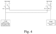
- motive power supply and auxiliary power supply of any eight-carriage motor train unit are configured for a basic unit TUB 1
- a train-mounted battery of any motor train unit is configured as a basic unit TUB 2 .
- the phase ⁇ of the double-phase cut-off switches K 1 ⁇ is responsible for power supply of the basic unit TUB 1 of motive power supply and auxiliary power supply, and the phase ⁇ of the double-phase cut-off switches K 1 ⁇ is responsible for power supply of the basic unit TUB 2 of the train-mounted battery.
- the basic units TUB 1 and TUB 2 are two basic units that are independent from each other, mutually insulated and same in structure.
- the present invention combines technical innovations of the external power supply system, the input power supply system from external to internal, and the internal power supply system.
- the motor train unit successively runs through a plurality of travel sections including travel sections L 11 , L 12 , L 21 , L 22 , L 32 and the like during operation.
- the double-phase pantograph T 1 rises, the double-phase pantograph T 2 falls, the slide contactor ⁇ ′ on the left arm of the double-phase pantograph T 1 is connected to the basic unit TUB 1 of auxiliary power supply and motive power supply of the motor train unit, and the slide contactor ⁇ ′ on the right arm of the double-phase pantograph T 1 is connected to the basic unit TUB 2 of the train-mounted battery.
- the double-phase pantograph T 2 rises, the double-phase pantograph T 1 falls, the slide contactor ⁇ ′ on the right arm of the double-phase pantograph T 2 is connected to the basic unit TUB 2 of the train-mounted battery, and the slide contactor ⁇ ′ on the left arm of the double-phase pantograph T 2 is connected to the basic unit TUB 1 of auxiliary power supply and motive power supply of the motor train unit.
- the single phase ⁇ and the single phase ⁇ independently and alternately draw power from A, B and C of the three-phase high-voltage special power network in sections at intervals, the power of the single phase ⁇ and the power of the single phase ⁇ can be symmetrically adjusted automatically.
- the two single-phase power lines are not provided with a neutral section for passing of phase separation, and a negative sequence current is not caused in the three-phase high-voltage power network.
- both the double-phase pantographs T 1 and T 2 fall, and operation of the motor train unit in the travel section L 12 completely relies on electric energy stored in the travel section L 11 ; operation of the motor train unit in the travel section L 22 completely relies on electric energy stored in the travel section L 21 ; and operation of the motor train unit in the travel section L 32 completely relies on electric energy stored in the travel section L 31 .
- an overhead contact system for power supply is not required, and the train-mounted battery can supply power to keep operation of the motor train unit, and of course a support structure for the power supply network is not required, to achieve the objective of the present invention.
- None of the travel sections L 12 , L 22 and L 32 is provided with a traction power (supply) network, so tunnels, viaducts, station yards, culverts and the like can be intentionally set in these certain travel sections in line designing.
- the tunnels, viaducts, station yards, culverts and the like are intentionally provided in the travel sections L 12 , L 22 or L 32 in line designing.
- Many traction transformers can be saved in construction of the tunnels, viaducts, station yards, culverts and the like of the railway, and a lot of materials, machined parts and components and maintenance costs are saved in the support structure of the power supply network, and the safety of the railway is improved.
- the single-phase pantograph on the upline or the downline at the output of the traction transformer is improved to the double-phase pantograph, and the slide contactors ⁇ ′ and ⁇ ′ are respectively provided on the upper end of the left arm and the upper end of the right arm of the double-phase pantograph, and are respectively in good slide contact with the power of the single-phase ⁇ and the power of the single-phase ⁇ output by the traction transformer.
- Good insulation between the left arm and the right arm of the pantograph is achieved by insulators M 1 and M 2 .
- the upline and the downline of the railway may also be configured to be a support structure in three-line arrangement.
- the tension length supports and the positioners for cantilever on lateral sides of the upline and the downline are designed into L-type, and the tension length supports and the positioners for cantilever arranged between the upline and the downline may be designed into be T-type, which not only saves the cost of project construction, and also improves the stability, reliability and safety of the support structure of the special power network.
- Cantilevers are fixed to upper parts of the tension length supports, and two catenaries mutually insulated and parallel to each other are fixed to the cantilever. Each catenary is connected to an upper end of a hanger, and a lower end of the hanger is connected to a power supply contact wire.
- the two hangers and the two power supply contact wires are parallel to each other and mutually insulated. The two contact wires are respectively electrically connected to the power of the single-phase ⁇ and the power of the single-phase ⁇ output by the traction transformer.
- the power of the single-phase ⁇ and the power of the single-phase ⁇ are respectively in slide contact with the slide contactor ⁇ ′ and the slide contactor ⁇ ′ of the double-phase pantograph, and are input to the auxiliary power supply and motive power supply system and the train-mounted battery within the motor train unit via the double-phase cut-off switches K 1 ⁇ and K 1 ⁇ or K 2 ⁇ and K 2 ⁇ .
- the power of the single-phase ⁇ and the power of the single-phase ⁇ respectively supply power to the basic unit TUB 1 and the basic unit TUB 2
- the basic unit TUB 1 and the basic unit TUB 2 are mutually independent and symmetrical to each other. Therefore, no neutral section is provided, and a negative sequence current is not caused in the three-phase high-voltage power A, B and C.
- the original single-phase pantograph is changed to the double-phase pantograph, and as the slide contactor ⁇ ′ and the slide contactor ⁇ ′ of the pantograph are in slide contact with the power of the single-phase ⁇ and the power of the single-phase ⁇ , and the power of the single-phase ⁇ and the power of the single-phase ⁇ are parallel to and insulated from each other, the mechanical smoothness of slide contact of the pantograph, the transmission quality of electric energy and the reliability of power supply are improved.
- the upline and the downline of the railway may also be configured to be a support structure in three-line arrangement.
- the tension length supports and the positioners for cantilever on lateral sides of the upline and the downline are designed into L-type, and the tension length support and the positioners for cantilever arranged between the upline and the downline may be designed into be T-type, which not only saves the cost of project construction, but also improves the stability, reliability and safety of the support structure of the special power network.
- FIG. 1 is schematic front view of an electrified railway power grid system without negative sequence in the whole process and without power supply networks at intervals according to a preferred embodiment of the present invention
- FIG. 2 is a schematic bottom view of FIG. 1 ;
- FIG. 3( a ) is a side view along line B 1 -B 1 of FIG. 1
- FIG. 3( b ) is a side view along line B 2 -B 2 of FIG. 1 ;
- FIG. 4 is a schematic diagram of a motive power supply and auxiliary power supply load and a train-mounted battery of an eight-carriage motor train unit;
- FIG. 5 is a schematic diagram of external single-phase power supply of an existing electrified railway
- FIGS. 6( a )-6( d ) are schematic diagram of arrangement sequences and placement positions of double-phase pantographs of four eight-carriage motor train units of different types, wherein
- FIG. 6( a ) is a schematic diagram of grouping of CRH1-type motor trains
- FIG. 6( b ) is a schematic diagram of grouping of CRH2-type motor trains
- FIG. 6( c ) is a schematic diagram of grouping of CRH3-type motor trains.
- FIG. 6( d ) is a schematic diagram of grouping of CRH5-type motor trains.
- an electrified railway power grid system without negative sequence in the whole process and without power supply networks at intervals comprises tension length supports.
- Positioners for cantilever are fixed to upper parts of the tension length supports, and two parallel catenaries are fixed to each positioner for cantilever, with a distance of 1.94 m between the catenaries.
- Hangers are disposed between the catenaries and contact wires. The upper ends of the two parallel hangers are connected to the two catenaries, and the lower ends of the two hangers are connected to the two contact wires.
- the two parallel contact wires are respectively connected to two lines of single-phase power ⁇ and ⁇ output from a secondary side of a traction transformer S.
- Positioners for cantilever 3 are provided at upper parts of each row of tension length supports 2 , and two catenaries 4 parallel to each other are fixed to each positioner for cantilever 3 .
- Hangers 5 are provided between the catenaries 4 and the two single-phase power supply contact wires 1 .
- the spacing between every adjacent two positioners for cantilever 3 for each tension length is 35-45 m.
- the spacing between every adjacent two hangers 5 for each tension length is 7.5-8.5 m.
- the spacing between the two parallel hangers on each positioner for cantilever 3 is not less than 1.94 m.
- the hangers 5 transfer all weights of the power supply contact wires 1 to the catenaries 4 , and the catenaries 4 transfer all equipment load of the power supply contact wires 1 to the tension length supports 2 .
- three-phase (A, B and C) high-voltage special power of 110 KV (220 KV for high-speed trains) is input to a primary side of the traction transformer S, and two lines of single-phase power ⁇ and ⁇ of 27.5 KV (the rated voltage is 25 KV) are output from the secondary side of the traction transformer S.
- the single-phase power ⁇ and the single-phase power ⁇ are connected to the two power supply contact wires 1 .
- a support structure in three-line arrangement can be set for the upline and the downline of the railway, wherein the tension length supports and the cantilevers on lateral sides of the upline and the downline may be designed into L-type (L-shaped), and the tension length supports and the positioners for cantilever arranged between the upline and the downline may be designed into be T-type (T-shaped), which not only saves the cost of project construction, but also improves the stability, reliability and safety of the support structure of the special power network.
- a double-phase pantograph T 1 and a double-phase pantograph T 2 are provided on corresponding train tops of a motor train unit.
- a slide contactor ⁇ ′ and a slide contactor ⁇ ′ are respectively provided on an upper end of a left arm La and an upper end of a right arm Ra of each double-phase pantograph.
- the slide contactor ⁇ ′ and the slide contactor ⁇ ′ are in good slide contact with the two single-phase power supply wires.
- Insulators M 1 and M 2 are provided between the left arm La and the right arm Ra of the double-phase pantograph.
- the spacing between the left arm La and the right arm Ra of the double-phase pantograph is not less than 1.94 m.
- Power is transferred from the slide contactor ⁇ ′ and the slide contactor ⁇ ′ to the power supply system inside the motor train unit via the left arm La and the right arm Ra of the double-phase pantograph, which has the advantages of stable and smooth mechanical contact, reduced wear of pantograph-catenary contact, more reliable electric energy transmission, and high quality of power supply, as compared with the case of only providing one single-phase contactor in the middle of the pantograph.
- the two feeder lines of the single-phase power ⁇ and the single-phase power ⁇ are transferred from the slide contactor ⁇ and the slide contactor ⁇ to the power supply system inside the motor train unit via the left arm La and the right arm Ra of the double-phase pantograph; and the single-phase power ⁇ and the single-phase power ⁇ are connected to double-phase cut-off switches K 1 ⁇ and K 1 ⁇ , or are connected to double-phase cut-off switches K 2 ⁇ and K 2 ⁇ .
- the motor train unit will successively run through a plurality of travel sections including travel sections L 11 , L 12 , L 21 L 22 , L 32 and the like during operation.
- the double-phase pantograph T 1 rises, the double-phase pantograph T 2 falls, the double-phase cut-off switch K 2 ⁇ and K 2 ⁇ are turned off, the double-phase cut-off switch K 1 ⁇ is connected to a basic unit TUB 1 of motive power supply and auxiliary power supply within the motor train unit, and the double-phase cut-off switch K 1 ⁇ is connected to a basic unit TUB 2 of a train-mounted (storage) battery.
- the double-phase pantograph T 1 rises, the double-phase pantograph T 2 falls, the double-phase cut-off switch K 2 ⁇ and K 2 ⁇ are turned off, the double-phase cut-off switch K 1 ⁇ is connected to the basic unit TUB 1 of motive power supply and auxiliary power supply within the motor train unit, and the double-phase cut-off switch K 1 ⁇ is connected to the basic unit TUB 2 of the train-mounted battery; electric energy stored by the train-mounted battery in the travel section L 31 is sufficient to provide the motive power supply and auxiliary power supply needed by the motor train unit in the travel section L 32 ; and both the double-phase pantographs T 1 and T 2 fall in the travel section L 32 .
- the double-phase pantograph T 1 rises, the double-phase pantograph T 2 falls, the double-phase pantograph T 1 falls, and the double-phase pantograph T 1 rises.
- the basic unit TUB 1 and the basic unit TUB 2 draw power from the power network alternately.
- the electric quantity needed for the motive power supply and auxiliary power supply within the train is just approximate to that needed for the train-mounted battery power supply.
- the basic unit TUB 1 and the basic unit TUB 2 alternately draw power from the power network every time the double-phase pantograph T 1 rises or the double-phase pantograph T 2 rises, the negative sequence current caused by asymmetry of power drawing error accumulation will be reduced in the whole process.
- the above problem is solved desirably in the present invention, whereby power supply imbalance of the three-phase high-voltage power network due to accumulation of electric quantity will not occur, and negative effect of the negative sequence current is reduced.
- both the double-phase pantographs T 1 and T 2 fall, and operation of the motor train unit in the travel section L 12 completely relies on the electric energy stored in the travel section L 11 ; operation of the motor train unit in the travel section L 22 completely relies on the electric energy stored in the travel section L 21 ; and operation of the motor train unit in the travel section L 32 completely relies on the electric energy stored in the travel section L 31 .
- FIGS. 6( a )-6( d ) An exemplary application of the present invention in high-speed electrified trains is described below in conjunction with FIGS. 6( a )-6( d ) .
- High-speed electrified trains in China at present are divided into four types, which are all eight-carriage motor train units.
- single-phase pantographs originally provided on different train tops of a motor train unit are improved into double-phase pantographs.
- double-phase pantographs of an eight-carriage motor train unit of CRH1-type are provided on tops of a second carriage as a trailer and a seventh carriage as a trailer.
- double-phase pantographs of an eight-carriage motor train unit of CRH2-type are provided on tops of a fourth carriage as a trailer and a sixth carriage as a motor train.
- double-phase pantographs of an eight-carriage motor train unit of CRH3-type are provided on tops of a second carriage as a trailer and a seventh carriage as a trailer.
- double-phase pantographs of an eight-carriage motor train unit of CRH4-type are provided on tops of a third carriage as a trailer and a sixth carriage as a trailer.
- the two lines of single-phase power ⁇ and single-phase power ⁇ output from the secondary side of the traction transformer S pass through the slide contactor ⁇ ′ and the slide contactor ⁇ ′ on the upper end of the left arm La and the upper end of the right arm Ra of the double-phase pantograph respectively, and are input into the motor train unit via the double-phase cut-off switch K 1 ⁇ and K 1 ⁇ or K 2 ⁇ and K 2 ⁇ .
Landscapes
- Engineering & Computer Science (AREA)
- Mechanical Engineering (AREA)
- Power Engineering (AREA)
- Transportation (AREA)
- Life Sciences & Earth Sciences (AREA)
- Sustainable Development (AREA)
- Sustainable Energy (AREA)
- Electric Propulsion And Braking For Vehicles (AREA)
- Current-Collector Devices For Electrically Propelled Vehicles (AREA)
Abstract
Description
-
- A, B, C: three-phase high-voltage special power network
- D: motor train
- F: feeder line
- G: generator
- R: rail
- S: traction transformer
- T: overhead contact system
- α, β: two lines of single-phase power
- T1, T2: double-phase pantograph
- TM1: boosting transformer
- TM2: step-down transformer
- K1α, K1β and K2α, K2β: double-phase cut-off switch
- Rα and Rβ: large-current dropping resistor
- α′ and β′: slide contactors on an upper end of a left arm La and an upper end of a right arm Ra
- M1, M2: insulator between the left arm La and the right arm Ra
- 1: power supply contact wire
- 2: tension length support
- 3: positioner for cantilever
- 4: catenary
- 5: hanger
Claims (7)
Applications Claiming Priority (4)
| Application Number | Priority Date | Filing Date | Title |
|---|---|---|---|
| CN201410409606.0 | 2014-08-19 | ||
| CN201410409606.0A CN104210385B (en) | 2014-08-19 | 2014-08-19 | The omnidistance electric railway network system without negative phase-sequence interval unpowered net |
| CN201410409606 | 2014-08-19 | ||
| PCT/CN2015/086817 WO2016026404A1 (en) | 2014-08-19 | 2015-08-13 | Electrified railway power grid system without negative sequence in whole process and without power supply networks at intervals |
Publications (2)
| Publication Number | Publication Date |
|---|---|
| US20180345822A1 US20180345822A1 (en) | 2018-12-06 |
| US10850637B2 true US10850637B2 (en) | 2020-12-01 |
Family
ID=52092442
Family Applications (1)
| Application Number | Title | Priority Date | Filing Date |
|---|---|---|---|
| US15/504,296 Expired - Fee Related US10850637B2 (en) | 2014-08-19 | 2015-08-13 | Electrified railway power grid system without negative sequence in whole process and without power supply networks at intervals |
Country Status (4)
| Country | Link |
|---|---|
| US (1) | US10850637B2 (en) |
| CN (1) | CN104210385B (en) |
| RU (1) | RU2675765C2 (en) |
| WO (1) | WO2016026404A1 (en) |
Families Citing this family (23)
| Publication number | Priority date | Publication date | Assignee | Title |
|---|---|---|---|---|
| CN104210385B (en) * | 2014-08-19 | 2016-09-07 | 吉林大学 | The omnidistance electric railway network system without negative phase-sequence interval unpowered net |
| CN104590524B (en) * | 2015-02-02 | 2018-11-13 | 王友准 | New Ship Transportation System Driven by Electric Motor and Internal Combustion Engine |
| CN107472037B (en) * | 2016-06-07 | 2020-06-12 | 吉林大学 | Traction power supply system for high-speed train and vehicle-mounted storage and discharge system thereof |
| RU2700238C1 (en) * | 2016-06-07 | 2019-09-13 | Цзилинь Юниверсити | Traction power system for high-speed train and its on-board energy and discharge accumulation system |
| EP3568315A1 (en) * | 2017-02-21 | 2019-11-20 | Siemens Mobility GmbH | Electrified road transport system |
| CN107499190B (en) * | 2017-09-25 | 2023-09-22 | 吉林大学 | Energy storage and discharge system for power traction and regenerative braking of high-speed EMUs |
| CN109033627B (en) * | 2018-07-25 | 2022-09-09 | 西南交通大学 | A method for constructing a train-over-phase vehicle-network-bridge coupling model |
| CN110857039B (en) * | 2018-08-23 | 2021-11-09 | 中铁第四勘察设计院集团有限公司 | Contact net anchor section joint power supply conversion method and system |
| CN110212501B (en) * | 2019-06-20 | 2021-07-02 | 西南交通大学 | A control method for fault tripping of AT power supply system of electrified railway |
| RU2729869C1 (en) * | 2019-07-01 | 2020-08-12 | Борис Алексеевич Аржанников | Traction power system of ac railroads |
| CN111086391B (en) * | 2019-11-18 | 2025-03-14 | 中铁二院工程集团有限责任公司 | A dual-power supply system for tourist rail transit |
| CN110979105B (en) * | 2019-12-24 | 2022-06-14 | 中铁二院工程集团有限责任公司 | Design method for external power supply access scheme of through bilateral traction power supply system |
| CN111319517B (en) * | 2020-03-04 | 2022-05-10 | 西南交通大学 | Method for detecting position of train pantograph in virtual in-phase power supply system |
| CN111391721B (en) * | 2020-04-16 | 2022-09-16 | 中铁二院工程集团有限责任公司 | A contact net structure for sparse rescue in railway tunnel |
| CN113829899B (en) * | 2020-06-24 | 2023-04-07 | 比亚迪股份有限公司 | Train, and train charging control method and equipment |
| US11999267B2 (en) * | 2021-01-20 | 2024-06-04 | Abb Schweiz Ag | Power line system with ripple generator for electric vehicles |
| CN112861406B (en) * | 2021-02-07 | 2022-12-27 | 河南科技大学 | Current-carrying tribology test-based bow net structure parameter optimization method |
| CN113002597B (en) * | 2021-04-23 | 2022-07-08 | 重庆中车长客轨道车辆有限公司 | Rescue system for dead zone |
| CN113060186B (en) * | 2021-04-23 | 2022-07-08 | 重庆中车长客轨道车辆有限公司 | Rescue method for non-electricity zone |
| CN113263920B (en) * | 2021-04-27 | 2022-05-17 | 西南交通大学 | Vehicle-mounted hybrid energy storage system of electrified railway and energy management method thereof |
| CN113659447B (en) * | 2021-07-20 | 2023-07-28 | 许继集团有限公司 | Method for automatically correcting sampling polarity of series-connection side voltage of in-phase power supply device |
| CN114312922A (en) * | 2021-12-30 | 2022-04-12 | 国能铁路装备有限责任公司 | Shunting system of power distributed motor train unit and power distributed motor train unit |
| CN120893130B (en) * | 2025-09-30 | 2026-02-03 | 西安交通大学 | Vehicle network model modeling method and system under working condition of cutting magnetic force lines by pantograph |
Citations (17)
| Publication number | Priority date | Publication date | Assignee | Title |
|---|---|---|---|---|
| JPS4916456B1 (en) | 1970-11-18 | 1974-04-22 | ||
| US5293947A (en) * | 1991-09-03 | 1994-03-15 | Wagner Mining And Construction Equipment Co. | Variable speed AC electric drive vehicle |
| EP0769407A1 (en) | 1995-10-20 | 1997-04-23 | Paul Keller Ingenieurbüro Ag | Travelling railway overhead line |
| US5788033A (en) | 1996-07-19 | 1998-08-04 | Krupp Fordertechnik Gmbh | Arrangement for supplying power to an electric locomotive |
| JP2003319505A (en) | 2002-04-19 | 2003-11-07 | Sumitomo Metal Ind Ltd | Anomaly detection device for multiple pantographs |
| JP3917118B2 (en) | 2003-08-28 | 2007-05-23 | 独立行政法人鉄道建設・運輸施設整備支援機構 | Connecting hangers for train lines |
| CN101073994A (en) | 2007-06-19 | 2007-11-21 | 中铁电气化局集团有限公司 | Contact network system of high-speed electric railway |
| CN201077368Y (en) | 2007-10-22 | 2008-06-25 | 西南交通大学 | Electrified railroad homophase traction power supply system |
| CN101503064A (en) | 2009-02-23 | 2009-08-12 | 吴加林 | Through type non-phase separation balanced power supply electrified railroad traction system |
| WO2009133608A1 (en) | 2008-04-30 | 2009-11-05 | 三菱電機株式会社 | Electric railway system |
| CN101746282A (en) | 2010-03-12 | 2010-06-23 | 西南交通大学 | Electrified railroad through power supply system without split phase |
| CN201712489U (en) | 2010-07-03 | 2011-01-19 | 衡水宝力铁路电气化器材有限公司 | Partial-tension high-elasticity compensating contact net |
| US20120032533A1 (en) * | 2009-04-23 | 2012-02-09 | Kabushiki Kaisha Toshiba | Electric motor car control system |
| JP4916456B2 (en) | 2008-01-24 | 2012-04-11 | 東日本旅客鉄道株式会社 | Heat radiation train line device |
| US8217799B2 (en) * | 2006-11-10 | 2012-07-10 | Bitimec S.R.L. | System for monitoring the state of electrical power supply and mechanical tension in an overhead contact line |
| CN202319965U (en) | 2011-11-16 | 2012-07-11 | 中铁二院昆明勘察设计研究院有限责任公司 | Standard-meter sleeved track straight-line segment shared contact net |
| CN104210385A (en) | 2014-08-19 | 2014-12-17 | 吉林大学 | Electrified railway power grid system without negative sequence or spaced power supply networks in whole process |
-
2014
- 2014-08-19 CN CN201410409606.0A patent/CN104210385B/en not_active Expired - Fee Related
-
2015
- 2015-08-13 RU RU2017108943A patent/RU2675765C2/en active
- 2015-08-13 WO PCT/CN2015/086817 patent/WO2016026404A1/en not_active Ceased
- 2015-08-13 US US15/504,296 patent/US10850637B2/en not_active Expired - Fee Related
Patent Citations (17)
| Publication number | Priority date | Publication date | Assignee | Title |
|---|---|---|---|---|
| JPS4916456B1 (en) | 1970-11-18 | 1974-04-22 | ||
| US5293947A (en) * | 1991-09-03 | 1994-03-15 | Wagner Mining And Construction Equipment Co. | Variable speed AC electric drive vehicle |
| EP0769407A1 (en) | 1995-10-20 | 1997-04-23 | Paul Keller Ingenieurbüro Ag | Travelling railway overhead line |
| US5788033A (en) | 1996-07-19 | 1998-08-04 | Krupp Fordertechnik Gmbh | Arrangement for supplying power to an electric locomotive |
| JP2003319505A (en) | 2002-04-19 | 2003-11-07 | Sumitomo Metal Ind Ltd | Anomaly detection device for multiple pantographs |
| JP3917118B2 (en) | 2003-08-28 | 2007-05-23 | 独立行政法人鉄道建設・運輸施設整備支援機構 | Connecting hangers for train lines |
| US8217799B2 (en) * | 2006-11-10 | 2012-07-10 | Bitimec S.R.L. | System for monitoring the state of electrical power supply and mechanical tension in an overhead contact line |
| CN101073994A (en) | 2007-06-19 | 2007-11-21 | 中铁电气化局集团有限公司 | Contact network system of high-speed electric railway |
| CN201077368Y (en) | 2007-10-22 | 2008-06-25 | 西南交通大学 | Electrified railroad homophase traction power supply system |
| JP4916456B2 (en) | 2008-01-24 | 2012-04-11 | 東日本旅客鉄道株式会社 | Heat radiation train line device |
| WO2009133608A1 (en) | 2008-04-30 | 2009-11-05 | 三菱電機株式会社 | Electric railway system |
| CN101503064A (en) | 2009-02-23 | 2009-08-12 | 吴加林 | Through type non-phase separation balanced power supply electrified railroad traction system |
| US20120032533A1 (en) * | 2009-04-23 | 2012-02-09 | Kabushiki Kaisha Toshiba | Electric motor car control system |
| CN101746282A (en) | 2010-03-12 | 2010-06-23 | 西南交通大学 | Electrified railroad through power supply system without split phase |
| CN201712489U (en) | 2010-07-03 | 2011-01-19 | 衡水宝力铁路电气化器材有限公司 | Partial-tension high-elasticity compensating contact net |
| CN202319965U (en) | 2011-11-16 | 2012-07-11 | 中铁二院昆明勘察设计研究院有限责任公司 | Standard-meter sleeved track straight-line segment shared contact net |
| CN104210385A (en) | 2014-08-19 | 2014-12-17 | 吉林大学 | Electrified railway power grid system without negative sequence or spaced power supply networks in whole process |
Non-Patent Citations (5)
| Title |
|---|
| Chinese Office Action and Search Report for application No. 201410409606.0, dated Dec. 17, 2015. |
| International Search Report for application No. PCT/CN2015/086817 dated Oct. 10, 2015. |
| Russian Office Action and Search Report for application No. 2017108943, dated Jul. 11, 2018. |
| Wikipedia-China Railway CRH1 (edited Jun. 2020) (Year: 2020). * |
| Wikipedia—China Railway CRH1 (edited Jun. 2020) (Year: 2020). * |
Also Published As
| Publication number | Publication date |
|---|---|
| BR112017003045A2 (en) | 2017-11-21 |
| CN104210385B (en) | 2016-09-07 |
| CN104210385A (en) | 2014-12-17 |
| US20180345822A1 (en) | 2018-12-06 |
| RU2017108943A3 (en) | 2018-09-20 |
| WO2016026404A1 (en) | 2016-02-25 |
| RU2017108943A (en) | 2018-09-20 |
| RU2675765C2 (en) | 2018-12-24 |
Similar Documents
| Publication | Publication Date | Title |
|---|---|---|
| US10850637B2 (en) | Electrified railway power grid system without negative sequence in whole process and without power supply networks at intervals | |
| JP6421238B2 (en) | Power supply system by cable in electric railway | |
| CN104015632B (en) | High speed passenger dedicated railway EMUs whole process did not establish the power supply system of phase-splitting | |
| CN110239398A (en) | A tripping method for feeder protection of traction substation with same-phase power supply | |
| CN105109362B (en) | A kind of electric railway traction power supply system | |
| CN101348086B (en) | Pulsating DC traction power supply system | |
| CN109065338B (en) | In-phase traction transformer | |
| CN101767540B (en) | Automatic neutral section passing device without switch switching for electrified railway | |
| CN108909541B (en) | A power supply structure for an electrified railway AT station | |
| RU2552572C1 (en) | 25 kv alternating current supply system for electrified railroads | |
| CN109484254B (en) | Power supply topological structure for passing neutral section of high-speed railway system and control method | |
| CN104369676B (en) | High speed passenger dedicated railway is omnidistance without negative phase-sequence power supply system | |
| CN203920466U (en) | A kind of electrified railway coaxial cable power supply system | |
| CN219277290U (en) | Combined flexible automatic neutral section passing device for electrified railway and compound line traction power supply system thereof | |
| WO2021098650A1 (en) | Traction power supply system structure applying single-phase traction transformer | |
| CN212435371U (en) | Rail transit power supply system | |
| CN213676388U (en) | Train three-phase power supply structure and system | |
| CN116001657A (en) | Combined flexible automatic neutral section passing device for electrified railway and control method thereof | |
| CN112039085A (en) | Rail transit power supply system | |
| CN110154794B (en) | A mobile segmented power supply inductive power transmission system | |
| RU2795966C1 (en) | Ac power supply system with distributed power supply | |
| CN114552563A (en) | Power supply system for rail transit power illumination | |
| CN112208340A (en) | Train three-phase power supply structure and system | |
| BR112017003045B1 (en) | ELECTRIFIED RAILWAY ELECTRIC NETWORK SYSTEM WITHOUT NEGATIVE SEQUENCE IN THE WHOLE PROCESS AND WITHOUT POWER SUPPLY NETWORKS IN THE INTERVALS | |
| RU2714196C1 (en) | Device for limitation of equalizing current in alternating current contact network |
Legal Events
| Date | Code | Title | Description |
|---|---|---|---|
| AS | Assignment |
Owner name: JILIN UNIVERSITY, CHINA Free format text: ASSIGNMENT OF ASSIGNORS INTEREST;ASSIGNORS:SONG, YUQUAN;GUAN, XIAOFANG;REEL/FRAME:042557/0360 Effective date: 20161103 |
|
| STPP | Information on status: patent application and granting procedure in general |
Free format text: APPLICATION DISPATCHED FROM PREEXAM, NOT YET DOCKETED |
|
| STPP | Information on status: patent application and granting procedure in general |
Free format text: DOCKETED NEW CASE - READY FOR EXAMINATION |
|
| STPP | Information on status: patent application and granting procedure in general |
Free format text: NON FINAL ACTION MAILED |
|
| STPP | Information on status: patent application and granting procedure in general |
Free format text: RESPONSE TO NON-FINAL OFFICE ACTION ENTERED AND FORWARDED TO EXAMINER |
|
| FEPP | Fee payment procedure |
Free format text: ENTITY STATUS SET TO MICRO (ORIGINAL EVENT CODE: MICR); ENTITY STATUS OF PATENT OWNER: MICROENTITY |
|
| STCF | Information on status: patent grant |
Free format text: PATENTED CASE |
|
| FEPP | Fee payment procedure |
Free format text: MAINTENANCE FEE REMINDER MAILED (ORIGINAL EVENT CODE: REM.); ENTITY STATUS OF PATENT OWNER: MICROENTITY |
|
| LAPS | Lapse for failure to pay maintenance fees |
Free format text: PATENT EXPIRED FOR FAILURE TO PAY MAINTENANCE FEES (ORIGINAL EVENT CODE: EXP.); ENTITY STATUS OF PATENT OWNER: MICROENTITY |
|
| STCH | Information on status: patent discontinuation |
Free format text: PATENT EXPIRED DUE TO NONPAYMENT OF MAINTENANCE FEES UNDER 37 CFR 1.362 |
|
| FP | Lapsed due to failure to pay maintenance fee |
Effective date: 20241201 |