US10849070B2 - Method for transmitting or receiving wake-up radio frame in wireless LAN system and apparatus therefor - Google Patents
Method for transmitting or receiving wake-up radio frame in wireless LAN system and apparatus therefor Download PDFInfo
- Publication number
- US10849070B2 US10849070B2 US16/467,025 US201716467025A US10849070B2 US 10849070 B2 US10849070 B2 US 10849070B2 US 201716467025 A US201716467025 A US 201716467025A US 10849070 B2 US10849070 B2 US 10849070B2
- Authority
- US
- United States
- Prior art keywords
- wur
- frame
- length
- sta
- information
- Prior art date
- Legal status (The legal status is an assumption and is not a legal conclusion. Google has not performed a legal analysis and makes no representation as to the accuracy of the status listed.)
- Active
Links
- 238000000034 method Methods 0.000 title claims abstract description 80
- 230000005540 biological transmission Effects 0.000 description 61
- 230000008569 process Effects 0.000 description 35
- 230000004044 response Effects 0.000 description 32
- 238000010586 diagram Methods 0.000 description 19
- 238000007726 management method Methods 0.000 description 18
- 230000007246 mechanism Effects 0.000 description 18
- 230000006870 function Effects 0.000 description 13
- 101100395869 Escherichia coli sta3 gene Proteins 0.000 description 10
- 230000011664 signaling Effects 0.000 description 10
- 239000000523 sample Substances 0.000 description 9
- 101100161473 Arabidopsis thaliana ABCB25 gene Proteins 0.000 description 8
- 101100096893 Mus musculus Sult2a1 gene Proteins 0.000 description 8
- 101150081243 STA1 gene Proteins 0.000 description 8
- 230000009471 action Effects 0.000 description 8
- 230000015654 memory Effects 0.000 description 7
- OVGWMUWIRHGGJP-WVDJAODQSA-N (z)-7-[(1s,3r,4r,5s)-3-[(e,3r)-3-hydroxyoct-1-enyl]-6-thiabicyclo[3.1.1]heptan-4-yl]hept-5-enoic acid Chemical compound OC(=O)CCC\C=C/C[C@@H]1[C@@H](/C=C/[C@H](O)CCCCC)C[C@@H]2S[C@H]1C2 OVGWMUWIRHGGJP-WVDJAODQSA-N 0.000 description 6
- 101000988961 Escherichia coli Heat-stable enterotoxin A2 Proteins 0.000 description 6
- 230000002093 peripheral effect Effects 0.000 description 6
- 238000004891 communication Methods 0.000 description 5
- 238000012545 processing Methods 0.000 description 5
- VYLDEYYOISNGST-UHFFFAOYSA-N bissulfosuccinimidyl suberate Chemical compound O=C1C(S(=O)(=O)O)CC(=O)N1OC(=O)CCCCCCC(=O)ON1C(=O)C(S(O)(=O)=O)CC1=O VYLDEYYOISNGST-UHFFFAOYSA-N 0.000 description 4
- 230000001419 dependent effect Effects 0.000 description 4
- 101000752249 Homo sapiens Rho guanine nucleotide exchange factor 3 Proteins 0.000 description 3
- 101100172132 Mus musculus Eif3a gene Proteins 0.000 description 3
- 102100021689 Rho guanine nucleotide exchange factor 3 Human genes 0.000 description 3
- 125000004122 cyclic group Chemical group 0.000 description 3
- 230000000694 effects Effects 0.000 description 3
- 108700026140 MAC combination Proteins 0.000 description 2
- 230000008901 benefit Effects 0.000 description 2
- 238000012549 training Methods 0.000 description 2
- HMUNWXXNJPVALC-UHFFFAOYSA-N 1-[4-[2-(2,3-dihydro-1H-inden-2-ylamino)pyrimidin-5-yl]piperazin-1-yl]-2-(2,4,6,7-tetrahydrotriazolo[4,5-c]pyridin-5-yl)ethanone Chemical compound C1C(CC2=CC=CC=C12)NC1=NC=C(C=N1)N1CCN(CC1)C(CN1CC2=C(CC1)NN=N2)=O HMUNWXXNJPVALC-UHFFFAOYSA-N 0.000 description 1
- VZSRBBMJRBPUNF-UHFFFAOYSA-N 2-(2,3-dihydro-1H-inden-2-ylamino)-N-[3-oxo-3-(2,4,6,7-tetrahydrotriazolo[4,5-c]pyridin-5-yl)propyl]pyrimidine-5-carboxamide Chemical compound C1C(CC2=CC=CC=C12)NC1=NC=C(C=N1)C(=O)NCCC(N1CC2=C(CC1)NN=N2)=O VZSRBBMJRBPUNF-UHFFFAOYSA-N 0.000 description 1
- LDXJRKWFNNFDSA-UHFFFAOYSA-N 2-(2,4,6,7-tetrahydrotriazolo[4,5-c]pyridin-5-yl)-1-[4-[2-[[3-(trifluoromethoxy)phenyl]methylamino]pyrimidin-5-yl]piperazin-1-yl]ethanone Chemical compound C1CN(CC2=NNN=C21)CC(=O)N3CCN(CC3)C4=CN=C(N=C4)NCC5=CC(=CC=C5)OC(F)(F)F LDXJRKWFNNFDSA-UHFFFAOYSA-N 0.000 description 1
- YLZOPXRUQYQQID-UHFFFAOYSA-N 3-(2,4,6,7-tetrahydrotriazolo[4,5-c]pyridin-5-yl)-1-[4-[2-[[3-(trifluoromethoxy)phenyl]methylamino]pyrimidin-5-yl]piperazin-1-yl]propan-1-one Chemical compound N1N=NC=2CN(CCC=21)CCC(=O)N1CCN(CC1)C=1C=NC(=NC=1)NCC1=CC(=CC=C1)OC(F)(F)F YLZOPXRUQYQQID-UHFFFAOYSA-N 0.000 description 1
- NIPNSKYNPDTRPC-UHFFFAOYSA-N N-[2-oxo-2-(2,4,6,7-tetrahydrotriazolo[4,5-c]pyridin-5-yl)ethyl]-2-[[3-(trifluoromethoxy)phenyl]methylamino]pyrimidine-5-carboxamide Chemical compound O=C(CNC(=O)C=1C=NC(=NC=1)NCC1=CC(=CC=C1)OC(F)(F)F)N1CC2=C(CC1)NN=N2 NIPNSKYNPDTRPC-UHFFFAOYSA-N 0.000 description 1
- AFCARXCZXQIEQB-UHFFFAOYSA-N N-[3-oxo-3-(2,4,6,7-tetrahydrotriazolo[4,5-c]pyridin-5-yl)propyl]-2-[[3-(trifluoromethoxy)phenyl]methylamino]pyrimidine-5-carboxamide Chemical compound O=C(CCNC(=O)C=1C=NC(=NC=1)NCC1=CC(=CC=C1)OC(F)(F)F)N1CC2=C(CC1)NN=N2 AFCARXCZXQIEQB-UHFFFAOYSA-N 0.000 description 1
- 238000013461 design Methods 0.000 description 1
- 238000001514 detection method Methods 0.000 description 1
- 238000005516 engineering process Methods 0.000 description 1
- 239000012634 fragment Substances 0.000 description 1
- 230000000977 initiatory effect Effects 0.000 description 1
- 238000012423 maintenance Methods 0.000 description 1
- 238000012986 modification Methods 0.000 description 1
- 230000004048 modification Effects 0.000 description 1
- 230000000737 periodic effect Effects 0.000 description 1
- 230000002085 persistent effect Effects 0.000 description 1
- 230000010363 phase shift Effects 0.000 description 1
- 230000003252 repetitive effect Effects 0.000 description 1
- 230000003595 spectral effect Effects 0.000 description 1
- 230000001360 synchronised effect Effects 0.000 description 1
- 230000002618 waking effect Effects 0.000 description 1
Images


Classifications
-
- H—ELECTRICITY
- H04—ELECTRIC COMMUNICATION TECHNIQUE
- H04W—WIRELESS COMMUNICATION NETWORKS
- H04W52/00—Power management, e.g. TPC [Transmission Power Control], power saving or power classes
- H04W52/02—Power saving arrangements
- H04W52/0209—Power saving arrangements in terminal devices
- H04W52/0225—Power saving arrangements in terminal devices using monitoring of external events, e.g. the presence of a signal
- H04W52/0229—Power saving arrangements in terminal devices using monitoring of external events, e.g. the presence of a signal where the received signal is a wanted signal
-
- H—ELECTRICITY
- H04—ELECTRIC COMMUNICATION TECHNIQUE
- H04W—WIRELESS COMMUNICATION NETWORKS
- H04W28/00—Network traffic management; Network resource management
- H04W28/02—Traffic management, e.g. flow control or congestion control
- H04W28/06—Optimizing the usage of the radio link, e.g. header compression, information sizing, discarding information
-
- H—ELECTRICITY
- H04—ELECTRIC COMMUNICATION TECHNIQUE
- H04W—WIRELESS COMMUNICATION NETWORKS
- H04W52/00—Power management, e.g. TPC [Transmission Power Control], power saving or power classes
- H04W52/02—Power saving arrangements
-
- H—ELECTRICITY
- H04—ELECTRIC COMMUNICATION TECHNIQUE
- H04L—TRANSMISSION OF DIGITAL INFORMATION, e.g. TELEGRAPHIC COMMUNICATION
- H04L2101/00—Indexing scheme associated with group H04L61/00
- H04L2101/60—Types of network addresses
- H04L2101/618—Details of network addresses
- H04L2101/622—Layer-2 addresses, e.g. medium access control [MAC] addresses
-
- H04L61/6022—
-
- H—ELECTRICITY
- H04—ELECTRIC COMMUNICATION TECHNIQUE
- H04W—WIRELESS COMMUNICATION NETWORKS
- H04W84/00—Network topologies
- H04W84/02—Hierarchically pre-organised networks, e.g. paging networks, cellular networks, WLAN [Wireless Local Area Network] or WLL [Wireless Local Loop]
- H04W84/10—Small scale networks; Flat hierarchical networks
- H04W84/12—WLAN [Wireless Local Area Networks]
-
- Y—GENERAL TAGGING OF NEW TECHNOLOGICAL DEVELOPMENTS; GENERAL TAGGING OF CROSS-SECTIONAL TECHNOLOGIES SPANNING OVER SEVERAL SECTIONS OF THE IPC; TECHNICAL SUBJECTS COVERED BY FORMER USPC CROSS-REFERENCE ART COLLECTIONS [XRACs] AND DIGESTS
- Y02—TECHNOLOGIES OR APPLICATIONS FOR MITIGATION OR ADAPTATION AGAINST CLIMATE CHANGE
- Y02D—CLIMATE CHANGE MITIGATION TECHNOLOGIES IN INFORMATION AND COMMUNICATION TECHNOLOGIES [ICT], I.E. INFORMATION AND COMMUNICATION TECHNOLOGIES AIMING AT THE REDUCTION OF THEIR OWN ENERGY USE
- Y02D30/00—Reducing energy consumption in communication networks
- Y02D30/70—Reducing energy consumption in communication networks in wireless communication networks
-
- Y02D70/00—
-
- Y02D70/10—
-
- Y02D70/12—
-
- Y02D70/14—
Definitions
- the present invention relates to a wireless local area network system and, more particularly, to a method of transmitting or receiving a Wake-Up Radio (WUR) frame through a WUR to wake a Primary Connectivity Radio (PCR) and an apparatus therefor.
- WUR Wake-Up Radio
- PCR Primary Connectivity Radio
- IEEE 802.11a and b use an unlicensed band at 2.4 GHz or 5 GHz.
- IEEE 802.11b provides a transmission rate of 11 Mbps and IEEE 802.11a provides a transmission rate of 54 Mbps.
- IEEE 802.11g provides a transmission rate of 54 Mbps by applying Orthogonal Frequency Division Multiplexing (OFDM) at 2.4 GHz.
- IEEE 802.11n provides a transmission rate of 300 Mbps for four spatial streams by applying Multiple Input Multiple Output (MIMO)-OFDM.
- IEEE 802.11n supports a channel bandwidth of up to 40 MHz and, in this case, provides a transmission rate of 600 Mbps.
- IEEE 802.11ac uses a bandwidth of up to 160 MHz and supports a transmission rate of up to 1 Gbits/s for 8 spatial streams
- IEEE 802.11ax standards are under discussion.
- the present invention is not limited to the above technical problems and other technical objects may be inferred from embodiments of the present invention.
- a method of transmitting a Wake-Up Radio (WUR) frame by an Access Point (AP) in a Wireless Local Area Network (WLAN) system including generating a WUR frame including a WUR preamble and a Media Access Control (MAC) header; and transmitting the WUR frame, wherein the MAC header includes at least one of frame length information, a transmitter identifier (ID), and a receiver ID, and if the frame length information is included in the MAC header, the frame length information indicates the length of MAC content located after the WUR preamble in the WUR frame and the length of the MAC header is excluded from the indicated length of the MAC content.
- WUR Wake-Up Radio
- AP Access Point
- WLAN Wireless Local Area Network
- an Access Point for transmitting a Wake-Up Radio (WUR) frame in a Wireless Local Area Network (WLAN) system, including a processor configured to generate a WUR frame including a WUR preamble and a Media Access Control (MAC) header; and a transmitter configured to transmit the WUR frame, wherein the MAC header includes at least one of frame length information, a transmitter identifier (ID), and a receiver ID, and if the frame length information is included in the MAC header, the frame length information indicates the length of MAC content located after the WUR preamble in the WUR frame and the length of the MAC header is excluded from the indicated length of the MAC content.
- AP Access Point
- a station for receiving a Wake-Up Radio (WUR) frame in a Wireless Local Area Network (WLAN) system, including a receiver configured to receive a WUR frame including a WUR preamble and a Media Access Control (MAC) header; and a processor configured to decode the WUR frame, wherein the MAC header includes at least one of frame length information, a transmitter identifier (ID), and a receiver ID, and if the frame length information is included in the MAC header, the frame length information indicates the length of MAC content located after the WUR preamble in the WUR frame and the length of the MAC header is excluded from the indicated length of the MAC content.
- STA station
- WUR Wake-Up Radio
- WLAN Wireless Local Area Network
- the length of the MAC content indicated by the frame length information may include the length of a frame body of the WUR frame.
- the frame length information may be omitted from the MAC header. For example, only when the WUR frame corresponds to a variable length, the frame length information may be included in the MAC header. Whether the WUR frame corresponds to the predefined fixed length or the variable length may be indicated through the MAC header.
- the frame length information may indicate the length of the MAC content in units of predetermined bytes.
- the WUR preamble may include a sequence for time synchronization for the WUR frame, the transmitter ID may correspond to the AP, and the receiver ID may correspond to at least one station (STA) for receiving the WUR frame.
- STA station
- a WUR frame may be more efficiently and accurately transmitted or received by directly/indirectly indicating a WUR frame length through a MAC header.
- FIG. 1 illustrates an example of a configuration of a wireless LAN system.
- FIG. 2 illustrates another example of a configuration of a wireless LAN system.
- FIG. 3 illustrates a general link setup procedure
- FIG. 4 illustrates a backoff procedure
- FIG. 5 is an explanatory diagram of a hidden node and an exposed node.
- FIG. 6 is an explanatory diagram of RTS and CTS.
- FIGS. 7 to 9 are explanatory diagrams of operation of an STA that has received TIM.
- FIG. 10 is an explanatory diagram of an exemplary frame structure used in an IEEE 802.11 system.
- FIG. 11 is an explanatory diagram of a WUR receiver usable in a WLAN system (e.g., 802.11).
- FIG. 12 is an explanatory diagram of operation of a WUR receiver.
- FIG. 13 illustrates an example of a WUR packet.
- FIG. 14 illustrates the waveform of a WUR packet.
- FIG. 15 is an explanatory diagram of a WUR packet generated using an OFDM transmitter of a WLAN.
- FIG. 16 illustrates the structure of a WUR receiver.
- FIG. 17 illustrates a WUR duty cycle mode
- FIG. 18 illustrates an example of a MAC frame included in a WUR PPDU.
- FIG. 19 illustrates a WUR frame indicating length information through a WUR preamble according to an embodiment of the present invention.
- FIG. 20 illustrates a WUR frame indicating length information through an MPDU delimiter according to an embodiment of the present invention.
- FIG. 21 illustrates a WUR frame indicating length information through MAC content according to an embodiment of the present invention.
- FIG. 22 illustrates an exemplary WUR frame according to an embodiment of the present invention.
- FIG. 23 illustrates an exemplary WUR frame indicating length information through a WUR preamble according to an embodiment of the present invention.
- FIG. 24 illustrates an exemplary WUR frame indicating length information through a WUR preamble according to another embodiment of the present invention.
- FIG. 25 illustrates another exemplary WUR frame indicating length information according to the present invention.
- FIG. 26 illustrates a WUR frame indicating length information according to an embodiment of the present invention.
- FIG. 27 illustrates a WUR frame according to an embodiment of the present invention.
- FIG. 28 illustrates a WUR frame according to another embodiment of the present invention.
- FIG. 29 illustrates a flow of a WUR frame transmission method according to an embodiment of the present invention.
- FIG. 30 is an explanatory diagram of an apparatus according to an embodiment of the present invention.
- WLAN Wireless Local Area Network
- FIG. 1 is a diagram illustrating an exemplary configuration of a WLAN system.
- the WLAN system includes at least one Basic Service Set (BSS).
- BSS is a set of STAs that are able to communicate with each other by successfully performing synchronization.
- An STA is a logical entity including a physical layer interface between a Media Access Control (MAC) layer and a wireless medium.
- the STA may include an AP and a non-AP STA.
- a portable terminal manipulated by a user is the non-AP STA. If a terminal is simply called an STA, the STA refers to the non-AP STA.
- the non-AP STA may also be referred to as a terminal, a Wireless Transmit/Receive Unit (WTRU), a User Equipment (UE), a Mobile Station (MS), a mobile terminal, or a mobile subscriber unit.
- WTRU Wireless Transmit/Receive Unit
- UE User Equipment
- MS Mobile Station
- mobile terminal or a mobile subscriber unit.
- the AP is an entity that provides access to a Distribution System (DS) to an associated STA through a wireless medium.
- the AP may also be referred to as a centralized controller, a Base Station (BS), a Node-B, a Base Transceiver System (BTS), or a site controller.
- BS Base Station
- BTS Base Transceiver System
- the BSS may be divided into an infrastructure BSS and an Independent BSS (IBSS).
- IBSS Independent BSS
- the BSS illustrated in FIG. 1 is the IBSS.
- the IBSS refers to a BSS that does not include an AP. Since the IBSS does not include the AP, the IBSS is not allowed to access to the DS and thus forms a self-contained network.
- FIG. 2 is a diagram illustrating another exemplary configuration of a WLAN system.
- Each infrastructure BSS includes one or more STAs and one or more APs.
- communication between non-AP STAs is basically conducted via an AP. However, if a direct link is established between the non-AP STAs, direct communication between the non-AP STAs may be performed.
- the DS is a mechanism that connects a plurality of APs to one another.
- the DS is not necessarily a network. As long as it provides a distribution service, the DS is not limited to any specific form.
- the DS may be a wireless network such as a mesh network or may be a physical structure that connects APs to one another.
- An operation of an STA in a WLAN system may be described from the perspective of a layer architecture.
- a processor may implement the layer architecture in terms of device configuration.
- the STA may have a plurality of layers.
- the 802.11 standards mainly deal with a MAC sublayer and a PHY layer on a Data Link Layer (DLL).
- the PHY layer may include a Physical Layer Convergence Protocol (PLCP) entity, a Physical Medium Dependent (PMD) entity, and the like.
- PLCP Physical Layer Convergence Protocol
- PMD Physical Medium Dependent
- Each of the MAC sublayer and the PHY layer conceptually includes management entities called MAC sublayer Management Entity (MLME) and Physical Layer Management Entity (PLME). These entities provide layer management service interfaces through which a layer management function is executed.
- MLME MAC sublayer Management Entity
- PLME Physical Layer Management Entity
- a Station Management Entity resides in each STA.
- the SME is a layer independent entity which may be perceived as being present in a separate management plane or as being off to the side. While specific functions of the SME are not described in detail herein, the SME may be responsible for collecting layer-dependent states from various Layer Management Entities (LMEs) and setting layer-specific parameters to similar values. The SME may execute these functions and implement a standard management protocol on behalf of general system management entities.
- LMEs Layer Management Entities
- a primitive refers to a set of elements or parameters related to a specific purpose.
- An XX-GET.request primitive is used to request a predetermined MIB attribute value (management information-based attribute information).
- An XX-GET.confirm primitive is used to return an appropriate MIB attribute information value when the Status field indicates “Success” and to return an error indication in the Status field when the Status field does not indicate “Success”.
- An XX-SET.request primitive is used to request setting of an indicated MIB attribute to a predetermined value.
- the MIB attribute When the MIB attribute indicates a specific operation, the MIB attribute requests the specific operation to be performed.
- An XX-SET.confirm primitive is used to confirm that the indicated MIB attribute has been set to a requested value when the Status field indicates “Success” and to return an error condition in the Status field when the Status field does not indicate “Success”.
- the MIB attribute When the MIB attribute indicates a specific operation, it confirms that the operation has been performed.
- an STA In order to allow an STA to establish link setup on the network as well as to transmit/receive data over the network, the STA must perform such link setup through processes of network discovery, authentication, and association, and must establish association and perform security authentication.
- the link setup process may also be referred to as a session initiation process or a session setup process.
- an association step is a generic term for discovery, authentication, association, and security setup steps of the link setup process.
- STA may perform the network discovery action.
- the network discovery action may include the STA scanning action. That is, STA must search for an available network so as to access the network.
- the STA must identify a compatible network before participating in a wireless network.
- the process for identifying the network contained in a specific region is referred to as a scanning process.
- the scanning scheme is classified into active scanning and passive scanning.
- FIG. 3 is a flowchart illustrating a network discovery action including an active scanning process.
- an STA configured to perform scanning transmits a probe request frame and waits for a response to the probe request frame, such that the STA can move between channels and at the same time can determine which Access Point (AP) is present in a peripheral region.
- a responder transmits a probe response frame, acting as a response to the probe request frame, to the STA having transmitted the probe request frame.
- the responder may be an STA that has finally transmitted a beacon frame in a BSS of the scanned channel. In BSS, since the AP transmits the beacon frame, the AP operates as a responder.
- the responder since STAs of the IBSS sequentially transmit the beacon frame, the responder is not constant. For example, the STA, that has transmitted the probe request frame at Channel #1 and has received the probe response frame at Channel #1, stores BSS-associated information contained in the received probe response frame, and moves to the next channel (for example, Channel #2), such that the STA may perform scanning using the same method (i.e., probe request/response transmission/reception at Channel #2).
- the active scanning is more advantageous than the passive scanning in terms of delay and power consumption.
- the STA may perform the authentication process in step S 520 .
- the authentication process may be referred to as a first authentication process in such a manner that the authentication process can be clearly distinguished from the security setup process of step S 540 .
- the authentication process may include transmitting an authentication request frame to an AP by the STA, and transmitting an authentication response frame to the STA by the AP in response to the authentication request frame.
- the authentication frame used for authentication request/response may correspond to a management frame.
- the STA may transmit the authentication request frame to the AP.
- the AP may decide whether to authenticate the corresponding STA on the basis of information contained in the received authentication request frame.
- the AP may provide the authentication result to the STA through the authentication response frame.
- the association process may involve transmitting an association request frame to the AP by the STA, and transmitting an association response frame to the STA by the AP in response to the association request frame.
- the association request frame may include information associated with various capabilities, a beacon listen interval, a Service Set Identifier (SSID), supported rates, supported channels, RSN, mobility domain, supported operating classes, a TIM (Traffic Indication Map) broadcast request, interworking service capability, etc.
- SSID Service Set Identifier
- supported rates supported channels
- RSN mobility domain
- supported operating classes e.g., mobility management services, etc.
- TIM Traffic Indication Map
- the association response frame may include information associated with various capabilities, a state code, an Association ID (AID), supported rates, an Enhanced Distributed Channel Access (EDCA) parameter set, a Received Channel Power Indicator (RCPI), a Received Signal to Noise Indicator (RSNI), mobility domain, a timeout interval (association comeback time), an overlapping BSS scan parameter, a TIM broadcast response, a Quality of Service (QoS) map, etc.
- AID Association ID
- EDCA Enhanced Distributed Channel Access
- RCPI Received Channel Power Indicator
- RSNI Received Signal to Noise Indicator
- mobility domain a timeout interval (association comeback time)
- association comeback time an overlapping BSS scan parameter
- a TIM broadcast response a Quality of Service (QoS) map, etc.
- QoS Quality of Service
- the above-mentioned information may correspond to some parts of information capable of being contained in the association request/response frame, may be replaced with other information, or may include additional information.
- a security setup process may be carried out in step S 540 .
- the security setup process of Step S 540 may be referred to as an authentication process based on Robust Security Network Association (RSNA) request/response.
- the authentication process of step S 520 may be referred to as a first authentication process, and the security setup process of Step S 540 may also be simply referred to as an authentication process.
- RSNA Robust Security Network Association
- the security setup process of Step S 540 may include a private key setup process through 4-way handshaking based on an Extensible Authentication Protocol over LAN (EAPOL) frame.
- the security setup process may also be carried out according to other security schemes not defined in IEEE 802.11 standards.
- the corresponding AP and/or STA does not start its own transmission, establishes a delay time (for example, a random backoff period) for medium access, and attempts to start frame transmission after waiting for a predetermined time.
- a delay time for example, a random backoff period
- HCF Hybrid Coordination Function
- PCF Point Coordination Function
- EDCA Enhanced Distributed Channel Access
- HCCA HCF Controlled Channel Access
- EDCA is achieved when the access scheme provided from a provider to a plurality of users is contention-based.
- HCCA is achieved by the contention-free-based channel access scheme based on the polling mechanism.
- HCF includes a medium access mechanism for improving Quality of Service (QoS) of WLAN, and may transmit QoS data in both a Contention Period (CP) and a Contention Free Period (CFP).
- QoS Quality of Service
- the STA continuously monitors the medium while counting down the backoff slot in response to the decided backoff count value. If the medium is monitored as the occupied state, the countdown stops and waits for a predetermined time. If the medium is in the idle state, the remaining countdown restarts.
- the STA 3 determines whether the medium is in the idle state during the DIFS, and may directly start frame transmission. In the meantime, the remaining STAs monitor whether the medium is in the busy state, and wait for a predetermined time. During the predetermined time, data to be transmitted may occur in each of STA 1 , STA 2 , and STA 5 . If the medium is in the idle state, each STA waits for the DIFS time and then performs countdown of the backoff slot in response to a random backoff count value selected by each STA.
- FIG. 4 The example of FIG.
- STA 2 selects the lowest backoff count value and STA 1 selects the highest backoff count value. That is, after STA 2 finishes backoff counting, the residual backoff time of STA 5 at a frame transmission start time is shorter than the residual backoff time of STA 1 .
- Each of STA 1 and STA 5 temporarily stops countdown while STA 2 occupies the medium, and waits for a predetermined time. If occupying of the STA 2 is finished and the medium re-enters the idle state, each of STA 1 and STA 5 waits for a predetermined time DIFS, and restarts backoff counting. That is, after the remaining backoff slot as long as the residual backoff time is counted down, frame transmission may start operation.
- STA 5 Since the residual backoff time of STA 5 is shorter than that of STA 1 , STA 5 starts frame transmission. Meanwhile, data to be transmitted may occur in STA 4 while STA 2 occupies the medium. In this case, if the medium is in the idle state, STA 4 waits for the DIFS time, performs countdown in response to the random backoff count value selected by the STA 4 , and then starts frame transmission.
- FIG. 4 exemplarily shows the case in which the residual backoff time of STA 5 is identical to the random backoff count value of STA 4 by chance. In this case, an unexpected collision may occur between STA 4 and STA 5 .
- each of STA 4 and STA 5 does not receive ACK, resulting in the occurrence of a failure in data transmission.
- each of STA 4 and STA 5 increases the CW value two times, and STA 4 or STA 5 may select a random backoff count value and then perform countdown.
- STA 1 waits for a predetermined time while the medium is in the occupied state due to transmission of STA 4 and STA 5 . In this case, if the medium is in the idle state, STA 1 waits for the DIFS time, and then starts frame transmission after lapse of the residual backoff time.
- the CSMA/CA mechanism includes not only a physical carrier sensing mechanism in which the AP and/or STA can directly sense the medium, but also a virtual carrier sensing mechanism.
- the virtual carrier sensing mechanism can solve some problems (such as a hidden node problem) encountered in the medium access.
- MAC of the WLAN system can utilize a Network Allocation Vector (NAV).
- NAV Network Allocation Vector
- the AP and/or STA each of which currently uses the medium or has authority to use the medium, may inform another AP and/or another STA for the remaining time in which the medium is available.
- the NAV value may correspond to a reserved time in which the medium will be used by the AP and/or STA configured to transmit the corresponding frame.
- AN STA having received the NAV value may prohibit medium access (or channel access) during the corresponding reserved time.
- NAV may be set according to the value of a ‘duration’ field of the MAC header of the frame.
- the robust collision detect mechanism has been proposed to reduce the probability of such collision, and as such a detailed description thereof will hereinafter be described with reference to FIGS. 7 and 8 .
- an actual carrier sensing range is different from a transmission range, it is assumed that the actual carrier sensing range is identical to the transmission range for convenience of description and better understanding of the present invention.
- FIG. 5 is a conceptual diagram illustrating a hidden node and an exposed node.
- FIG. 5( a ) exemplarily shows the hidden node.
- STA A communicates with STA B, and STA C has information to be transmitted.
- STA C may determine that the medium is in the idle state when performing carrier sensing before transmitting data to STA B, under the condition that STA A transmits information to STA B. Since transmission of STA A (i.e., occupied medium) may not be detected at the location of STA C, it is determined that the medium is in the idle state. In this case, STA B simultaneously receives information of STA A and information of STA C, resulting in the occurrence of collision.
- STA A may be considered as a hidden node of STA C.
- FIG. 5( b ) exemplarily shows an exposed node.
- STA C under the condition that STA B transmits data to STA A, STA C has information to be transmitted to STA D. If STA C performs carrier sensing, it is determined that the medium is occupied due to transmission of STA B. Therefore, although STA C has information to be transmitted to STA D, the medium-occupied state is sensed, such that the STA C must wait for a predetermined time (i.e., standby mode) until the medium is in the idle state.
- a predetermined time i.e., standby mode
- STA C is referred to as an exposed node of STA B.
- FIG. 6 is a conceptual diagram illustrating Request To Send (RTS) and Clear To Send (CTS).
- RTS/CTS short signaling packet
- RTS/CTS between two STAs may be overheard by peripheral STA(s), such that the peripheral STA(s) may consider whether information is communicated between the two STAs. For example, if STA to be used for data transmission transmits the RTS frame to the STA having received data, the STA having received data transmits the CTS frame to peripheral STAs, and may inform the peripheral STAs that the STA is going to receive data.
- FIG. 6( a ) exemplarily shows the method for solving problems of the hidden node.
- STA A and STA C are ready to transmit data to STA B. If STA A transmits RTS to STA B, STA B transmits CTS to each of STA A and STA C located in the vicinity of the STA B. As a result, STA C must wait for a predetermined time until STA A and STA B stop data transmission, such that collision is prevented from occurring.
- FIG. 6( b ) exemplarily shows the method for solving problems of the exposed node.
- STA C performs overhearing of RTS/CTS transmission between STA A and STA B, such that STA C may determine no collision although it transmits data to another STA (for example, STA D). That is, STA B transmits an RTS to all peripheral STAs, and only STA A having data to be actually transmitted can transmit a CTS.
- STA C receives only the RTS and does not receive the CTS of STA A, such that it can be recognized that STA A is located outside of the carrier sensing range of STA C.
- the WLAN system has to perform channel sensing before STA performs data transmission/reception.
- the operation of always sensing the channel causes persistent power consumption of the STA.
- Continuous maintenance of the Rx state may cause large load to a power-limited STA (i.e., STA operated by a battery). Therefore, if STA maintains the Rx standby mode so as to persistently sense the channel, power is inefficiently consumed without special advantages in terms of WLAN throughput.
- the WLAN system supports a Power Management (PM) mode of the STA.
- PM Power Management
- the PM mode of the STA is classified into an active mode and a Power Save (PS) mode.
- the STA is basically operated in the active mode.
- the STA operating in the active mode maintains an awake state. If the STA is in the awake state, the STA may normally operate such that it can perform frame transmission/reception, channel scanning, or the like.
- STA operating in the PS mode is configured to switch from the doze state to the awake state or vice versa.
- STA operating in the sleep state is operated with minimum power, and the STA does not perform frame transmission/reception and channel scanning.
- the amount of power consumption is reduced in proportion to a specific time in which the STA stays in the sleep state, such that the STA operation time is increased in response to the reduced power consumption.
- it is impossible to transmit or receive the frame in the sleep state such that the STA cannot mandatorily operate for a long period of time.
- the STA operating in the sleep state is switched to the awake state, such that it can transmit/receive the frame in the awake state.
- the sleep-state STA is unable to receive the frame and cannot recognize the presence of a frame to be received.
- STA may need to switch to the awake state according to a specific period in order to recognize the presence or absence of a frame to be transmitted to the STA (or in order to receive a signal indicating the presence of the frame on the assumption that the presence of the frame to be transmitted to the STA is decided).
- the AP may transmit a beacon frame to STAs in a BSS at predetermined intervals.
- the beacon frame may include a traffic indication map (TIM) information element.
- the TIM information element may include information indicating that the AP has buffered traffic for STAs associated therewith and will transmit frames.
- TIM elements include a TIM used to indicate a unitcast frame and a delivery traffic indication map (DTIM) used to indicate a multicast or broadcast frame.
- DTIM delivery traffic indication map
- FIGS. 7 to 9 are conceptual diagrams illustrating detailed operations of the STA having received a Traffic Indication Map (TIM).
- TIM Traffic Indication Map
- STA is switched from the sleep state to the awake state so as to receive the beacon frame including a TIM from the AP.
- STA interprets the received TIM element such that it can recognize the presence or absence of buffered traffic to be transmitted to the STA.
- the STA may transmit the PS-Poll frame for requesting data frame transmission to the AP.
- the AP having received the PS-Poll frame transmitted by the STA may transmit the frame to the STA.
- STA may receive a data frame and then transmit an ACK frame to the AP in response to the received data frame. Thereafter, the STA may re-enter the sleep state.
- the AP may operate according to the immediate response scheme, such that the AP receives the PS-Poll frame from the STA and transmits the data frame after lapse of a predetermined time [for example, Short Inter-Frame Space (SIFS)].
- a predetermined time for example, Short Inter-Frame Space (SIFS)
- the AP having received the PS-Poll frame does not prepare a data frame to be transmitted to the STA during the SIFS time, such that the AP may operate according to the deferred response scheme, and as such a detailed description thereof will hereinafter be described with reference to FIG. 8 .
- the STA operations of FIG. 8 in which the STA is switched from the sleep state to the awake state, receives a TIM from the AP, and transmits the PS-Poll frame to the AP through contention are identical to those of FIG. 7 . If the AP having received the PS-Poll frame does not prepare a data frame during the SIFS time, the AP may transmit the ACK frame to the STA instead of transmitting the data frame. If the data frame is prepared after transmission of the ACK frame, the AP may transmit the data frame to the STA after completion of such contending. STA may transmit the ACK frame indicating successful reception of a data frame to the AP, and may be shifted to the sleep state.
- FIG. 9 shows the exemplary case in which AP transmits DTIM.
- STAs may be switched from the sleep state to the awake state so as to receive the beacon frame including a DTIM element from the AP.
- STAs may recognize that multicast/broadcast frame(s) will be transmitted through the received DTIM.
- AP may directly transmit data (i.e., multicast/broadcast frame) without transmitting/receiving the PS-Poll frame.
- the STAs While STAs continuously maintains the awake state after reception of the beacon frame including the DTIM, the STAs may receive data, and then switch to the sleep state after completion of data reception.
- FIG. 10 is an explanatory diagram of an exemplary frame structure used in an IEEE 802.11 system.
- a PPDU (Physical Layer Protocol Data Unit) frame format may include an STF (Short Training Field), an LTF (Long Training Field), a SIG (SIGNAL) field and a data field.
- the most basic (e.g., non-HT (High Throughput)) PPDU frame format may include only an L-STF (Legacy-STF), an L-LTF (Legacy-LTF), a SIG field and a data field.
- the STF is a signal for signal detection, AGC (Automatic Gain Control), diversity selection, accurate time synchronization, etc.
- the LTF is a signal for channel estimation, frequency error estimation, etc.
- the STF and LTF may be collectively called a PLCP preamble.
- the PLCP preamble may be regarded as a signal for OFDM physical layer synchronization and channel estimation.
- the SIG field may include a RATE field and a LENGTH field.
- the RATE field may include information about modulation and coding rates of data.
- the LENGTH field may include information about the length of data.
- the SIG field may include a parity bit, a SIG TAIL bit, etc.
- the data field may include a SERVICE field, a PSDU (Physical layer Service Data Unit) and a PPDU TAIL bit.
- the data field may also include padding bits as necessary. Some bits of the SERVICE field may be used for synchronization of a descrambler at a receiving end.
- the PSDU corresponds to an MPDU (MAC Protocol Data Unit) defined in the MAC layer and may include data generated/used in a higher layer.
- the PPDU TAIL bit may be used to return an encoder to state 0.
- the padding bits may be used to adjust the length of the data field to a predetermined unit.
- the MPDU is defined depending on various MAC frame formats, and a basic MAC frame includes a MAC header, a frame body and an FCS (Frame Check Sequence).
- the MAC frame may be composed of the MPDU and transmitted/received through PSDU of a data part of the PPDU frame format.
- the MAC header includes a frame control field, a duration/ID field, an address field, etc.
- the frame control field may include control information necessary for frame transmission/reception.
- the duration/ID field may be set to a time to transmit a relevant a relevant frame.
- the duration/ID field included in the MAC header may be set to a 16-bit length (e.g., B0 to B15). Content included in the duration/ID field may depend on frame type and sub-type, whether transmission is performed for a CFP (contention free period), QoS capability of a transmission STA and the like. (i) In a control frame corresponding to a sub-type of PS-Poll, the duration/ID field may include the AID of the transmission STA (e.g., through 14 LSBs) and 2 MSBs may be set to 1.
- the duration/ID field may be set to a fixed value (e.g., 32768).
- the duration/ID field may include a duration value defined per frame type.
- the actual TXOP duration indicated by B0 to B14 may be one of 0 to 32767 and the unit thereof may be microseconds ( ⁇ s).
- B15 can be set to 1 and B0 to B14 can be set to 0.
- B0 to B13 indicate one AID of 1 to 2007.
- the frame control field of the MAC header may include Protocol Version, Type, Subtype, To DS, From DS, More Fragment, Retry, Power Management, More Data, Protected Frame and Order subfields.
- Protocol Version Type, Subtype, To DS, From DS, More Fragment, Retry, Power Management, More Data, Protected Frame and Order subfields.
- an STA may support a Primary Connectivity Radio (PCR) (e.g., IEEE 802.11a/b/g/n/ac/ax WLAN), which is used for main wireless communication, and a Wake-Up Radio (WUR) (e.g., IEEE 802.11ba).
- PCR Primary Connectivity Radio
- WUR Wake-Up Radio
- the PCR is used for data transmission and reception and may be turned off when there is no data to be transmitted and received. In the case in which the PCR is turned off, if there is a packet to be received, a WURx of the STA may wake the PCR. Therefore, user data is transmitted through the PCR.
- the WURx may not be used for user data and may function only to wake a PCR transceiver.
- the WURx may be a simple type of receiver without a transmitter and is activated while the PCR is turned off. In an active state, target power consumption of the WURx desirably does not exceed 100 microwatts ( ⁇ W).
- a simple modulation scheme for example, On-Off Keying (OOK)
- OOK On-Off Keying
- a reception range (e.g., distance) aimed by the WURx may conform to current 802.11.
- FIG. 12 is an explanatory diagram of design and operation of a WUR packet.
- the WUR packet may include a PCR part 1200 and a WUR part 1205 .
- the PCR part 1200 is used for coexistence with a legacy WLAN system and the PCR part may be referred to as a WLAN preamble.
- a legacy WLAN may be included in the PCR part 1200 . Therefore, a third party legacy STA may be aware, through the PCR part 1200 of the WUR packet, that the WUR packet is not intended therefor and a medium of a PCR has been occupied by another STA.
- the WURx does not decode the PCR part of the WUR packet. This is because the WURx supporting narrowband and OOK demodulation does not support reception of a PCR signal.
- a WURx 1210 may consume very low power less than 100 ⁇ W as described above and may be implemented by a small, simple OOK demodulator.
- the WUR packet may include a preamble (e.g., an OFDM scheme) of a legacy WLAN and a new Low-Power (LP)-WUR signal waveform (e.g., an OOK scheme).
- a preamble e.g., an OFDM scheme
- LP Low-Power
- FIG. 13 illustrates an example of a WUR packet.
- the WUR packet of FIG. 13 includes a PCR part (e.g., a legacy WLAN preamble) for coexistence with a legacy STA.
- a PCR part e.g., a legacy WLAN preamble
- a WUR part may include at least one of a WUR preamble, a MAC header, a frame body, or an FCS.
- the WUR preamble may include, for example, a PN sequence.
- the MAC header may include a receiver address.
- the frame body may include other information necessary for wake-up.
- the FCS may include a Cyclic Redundancy Check (CRC).
- FIG. 14 illustrates the waveform of the WUR packet of FIG. 13 .
- one bit per OFDM symbol period e.g., 4 ⁇ sec
- a data rate of the WUR part may be 250 kbps.
- FIG. 15 is an explanatory diagram of a WUR packet generated using an OFDM transmitter of a WLAN.
- a Phase Shift Keying (PSK)-OFDM transmission scheme is used. If the WUR packet is generated by adding a separate OOK modulator for OOK modulation, implementation cost of a transmitter may increase. Therefore, a method of generating the OOK-modulated WUR packet by reusing an OFDM transmitter is considered.
- PSK Phase Shift Keying
- a bit value of 1 is modulated to a symbol having power of a threshold value or more (i.e., on) and a bit value of 0 is modulated to a symbol having power lower than the threshold value (i.e., off).
- the bit value of 1 may be defined as power ‘off’.
- the bit value of I/O is indicated through power-on/off at a corresponding symbol position.
- the above-described simple OOK modulation/demodulation scheme is advantageous in that power consumed to detect/demodulate a signal of a receiver and cost for receiver implementation may be reduced.
- OOK modulation for turning a signal of/off may be performed by reusing a legacy OFDM transmitter.
- the left graph of FIG. 15 illustrates a real part and an imaginary part of a normalized amplitude during one symbol period (e.g., 4 ⁇ sec) for an OOK-modulated bit value 1 by reusing an OFDM transmitter of a legacy WLAN. Since an OOK-modulated result for a bit value 0 corresponds to power-off, this is not illustrated.
- the right graph of FIG. 15 illustrates normalized Power Spectral Density (PSD) for an OOK-modulated bit value 1 on the frequency domain by reusing the OFDM transmitter of the legacy WLAN.
- PSD Power Spectral Density
- a center 4 MHz may be used for WUR in a corresponding band.
- WUR operates in a bandwidth of 4 MHz, this is for convenience of description and frequency bandwidths of other sizes may be used. In this case, it is desirable that WUR operate in a narrower bandwidth than an operating bandwidth of a PCR (e.g., the legacy WLAN) in order to reduce power.
- a PCR e.g., the legacy WLAN
- a subcarrier width (e.g., subcarrier spacing) is 312.5 kHz and an OOK pulse bandwidth corresponds to 13 subcarriers.
- IFFT Inverse Fast Fourier Transform
- the WUR packet may also be referred to as a WUR signal, a WUR frame, or a WUR PPDU.
- the WUR packet may be a packet for broadcast/multicast (e.g., a WUR beacon) or a packet for unicast (e.g., a packet for ending and then waking up a WUR mode of a specific WUR STA).
- FIG. 16 illustrates the structure of a WURx.
- the WURx may include an RF/analog front-end, a digital baseband processor, and a simple packet parser.
- FIG. 16 illustrates an exemplary structure of the WURx and the WURx of the present invention is not limited to the configuration of FIG. 16 .
- a WLAN STA having the WURx is simply referred to as a WUR STA.
- the WUR STA may be simply referred to as an STA.
- a re-discovery mechanism may be provided to enable an AP to re-discover a WUR STA which is in a WUR mode.
- An STA does not transmit a WUR frame while a PCR is turned off.
- the STA may have a duty cycle mode for WURx.
- the period of the WUR duty cycle may be a multiple of a basic unit.
- the basic unit may be indicated by the AP.
- An on-duration in each period for the WUR duty cycle may be larger than or equal to a minimum wake-up duration.
- the minimum wake-up duration is indicated by the AP.
- the AP may determine and indicate a starting point for WUR duty cycle schedule.
- the AP may provide explicit WUR mode signaling for causing the WUR STA to enter the WUR mode through the PCR.
- the WUR STA is notified of a WUR operating parameter through WUR mode signaling. If the STA of the WUR mode is in a doze state, a WURx follows duty cycle schedule (e.g., the WURx is always on) agreed upon between the AP and the STA.
- An existing negotiated service period between the AP and the STA for PCR schedule of the STA (e.g., a target wake-up time, schedule for a wireless network management sleep mode) may be suspended. If the service period is suspended, the STA does not need to wake up during the service period.
- the STA of the WUR mode is in a PS mode, the STA may not receive a PCR beacon frame. For example, while the STA configured to periodically wake up for a PCR PS mode operation and receive a PCR beacon frame operates in the WUR mode, the STA may not receive the PCR beacon frame.
- the AP may use EDCA as a channel access mechanism for transmitting a WUR frame.
- the AP may re-use 4 Access Categories (ACs) of PCR EDCA and EDCA parameters to transmit the WUR frame.
- the WUR frame may include a unicast wake-up frame, a multicast wake-up frame, and a WUR beacon frame.
- the AP may use any AC to transmit the multicast wake-up frame and/or the WUR frame. If there is no buffered frame to be transmitted to the STA, the AP may use any AC to transmit the unicast wake-up frame.
- the AP After the AP transmits the unicast wake-up frame, the AP waits for a predetermined timeout interval. If the AP receives any transmission from the STA during the timeout interval, the wake-up frame transmission is successful. Unlike this, if the AP fails to receive any transmission from the STA during the timeout interval, the wake-up frame transmission fails and the AP may retransmit the wake-up frame. If the STA receives the unicast wake-up frame through WUR, the STA should transmit a response frame to the AP using the PCR in response to the unicast wake-up frame.
- a multi-user wake-up frame may be defined to wake up multiple WUR mode STAs. After transmission of the broadcast wake-up frame, the AP may transmit broadcast/multicast frame through the PCR after a preparation period.
- FIG. 18 illustrates an example of a MAC layer frame (i.e., a WUR MAC frame) included in a WUR PPDU.
- the length of a MAC header may be fixed.
- An Address field of the MAC header may include at least one identifier.
- a Frame Control (FC) field of the MAC header includes a Type field indicating a type of the WUR frame. The Type field may indicate, for example, whether the WUR frame is a WUR beacon or a wake-up frame.
- a Type Dependent (TD) Control field of the MAC header includes TD control information of the WUR frame.
- a Frame Body field is optional and may be omitted from the WUR frame.
- the wake-up frame includes at least one of a transmitter identifier or a receiver identifier in the Address field.
- the Address field of the unicast wake-up frame includes a WUR identifier (ID) that identifies a receiver.
- the AP may indicate BSS parameter update or a group addressed Bufferable Unit (BU) by increasing a counter included in the wake-up frame.
- BU Bufferable Unit
- WLAN STAs (e.g., 3rd parties) operating in a PCR mode may be aware of the end of a WUR frame through a legacy 802.11 preamble (e.g., Length field of an L-SIG) included in the WUR frame and may not transmit PCR frames thereof during a duration in which the WUR frame is transmitted by configuring a channel as a busy state up to the end of the WUR frame.
- a legacy 802.11 preamble e.g., Length field of an L-SIG
- a WUR STA that waits for a payload of the WUR frame to be received in a WUR mode does not or cannot decode a non-WUR part (e.g., legacy 802.11 preamble) included in the WUR frame and may decode only a WUR part.
- a non-WUR part e.g., legacy 802.11 preamble
- the WUR STA may not be aware of the end of the WUR frame because the WUR STA could not read the Length field of the L-SIG included in the WUR frame.
- the WUR STA has difficulty in accurately decoding the WUR frame because the WUR STA is not aware of location information of an FCS of the WUR frame.
- length information regarding MAC content (e.g., MPDU) of the WUR frame may be indicated through a WUR preamble.
- a WUR SIG field is included in the WUR preamble and the length information is included in the WUR SIG field.
- the length information of the WUR SIG field may indicate length from the WUR SIG field to the end of the WUR frame.
- the length information of the WUR SIG field may indicate a timing at which the WUR frame is ended.
- FIG. 19 illustrates an example of indicating length information through a WUR preamble according to an embodiment of the present invention.
- the length information included in the WUR SIG field may indicate the length of content (e.g., MAC header+frame body+FCS) except for the WUR preamble.
- a byte unit may be used to indicate length.
- the length information included in the WUR SIG field may indicate how many bytes are used for MAC header+frame body+FCS.
- the length information may be located prior to the MAC content (e.g., MAC header+frame body+FCS) of the WUR frame.
- the length information may correspond to an MPDU delimiter.
- an indicator including length information may be attached in front of MAC content (e.g., in front of a MAC header).
- the indicator including the length information may indicate the length of the MAC content (e.g., MAC header+frame body+FCS).
- the indicator including the length information may indicate length from the start of the MAC header to a point at which the FCS is ended.
- the MPDU delimiter may include the FCS together with the length information.
- the FCS of the MPDU delimiter may correspond to a CRC of the MPDU delimiter including the length information.
- the term MPDU delimiter may be represented by other names.
- the STA performs reception operations corresponding to a maximum size of the WUR frame/PPDU.
- the maximum size of the WUR frame/PPDU may be determined in a system or may be acquired by the STA in a negotiation process with the AP. While the STA performs the reception operations corresponding to the maximum size of the WUR frame/PPDU, the STA may acquire accurate length information of the MAC frame from the MAC frame included in the WUR frame/PPDU or stop the WUR frame/PPDU reception operation in the last part of the MAC frame.
- the length information may be included in the MAC content of the WUR frame.
- the MAC header may include the length information.
- the MAC header may include the length information regardless of whether the WUR frame includes the frame body.
- a MAC header may include a Length field indicating the length information.
- the length information may indicate length up to the end of the MAC content (e.g., up to an FCS).
- the length information may indicate the entire length of the MAC content in predetermined bytes. Specifically, the length information may indicate the length of MAC header+frame body+FCS, including the Length field. Alternatively, the length information may indicate, in bytes, the length of the frame body except for the MAC header or the length of frame body+FCS in bytes except for the MAC header. If the length information (e.g., Length field) is located at the front part of the MAC header, a CRC attached after the Length field may be transmitted. In this case, the CRC may be a CRC for the Length field.
- Length field e.g., Length field
- the Length field is located at the front part of the MAC header, the present invention is not limited thereto.
- the location of the Length field may be changed or may be implicitly indicated through another field of the MAC header.
- the length information may be joint-encoded with other MAC header information.
- Padding bits (e.g., 0 to 7 bits) for byte alignment may be included in the MAC header or the frame body. For example, if a configuration unit of the MAC header or the frame body is bytes and the actual number N of information bits of the MAC header or the frame body is not a multiple of 8, at least one padding bit (e.g., 8-(N Modulo 8) padding bits) may be attached to the MAC header or the frame body.
- the present invention is not limited thereto.
- the Length field included in the L-SIG in the legacy system is 11 bits
- the length of the length information included in the WUR part of the WUR frame may be set to be smaller than 11 bits.
- the length information of the WUR frame included in the PCR part is 11 bits, but the length information of the WUR frame included in the WUR part may be set to be smaller than 11 bits.
- the unit of the length information included in the WUR part may be a unit (e.g., 2 bytes, 3 bytes, 4 bytes, 5 bytes, etc.) larger than one byte.
- Table 1 to Table 3 below list various examples of the length information included in the WUR part.
- the unit of the length information may be a unit (e.g., the unit of 4 bits) smaller than one byte.
- the size of padding bits may be one of 0 to 3 bits.
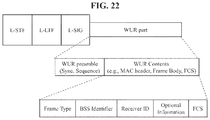
- FIG. 22 illustrates an exemplary WUR frame according to an embodiment of the present invention.
- content of the WUR frame may include at least one of a frame type, an address field (e.g., a BSS ID and/or a receiver ID), optional information, or an FCS.
- a portion of the content of the WUR frame may be referred to as a MAC header and the other portion may correspond to a frame body.
- FIG. 23 illustrates an exemplary WUR frame indicating length information through a WUR preamble according to an embodiment of the present invention.
- the WUR preamble includes a WUR sequence (e.g., synchronization sequence) and a WUR SIG field.
- a WUR mode STA may acquire time synchronization for the WUR frame through the WUR sequence and perform Automatic Gain Control (AGC).
- AWC Automatic Gain Control
- the WUR sequence performs a function similar to an L-STF of a PCR.
- the WUR SIG field may carry information needed to decode WUR frame content.
- the WUR SIG field may perform a function similar to a SIG (e.g., L-SIG, HT-SIG, VHT-SIG-A/B, HE-SIG-A/B, etc.) in a legacy WLAN system and include a part (e.g., CRC or parity check) for checking whether corresponding information is valid.
- a SIG e.g., L-SIG, HT-SIG, VHT-SIG-A/B, HE-SIG-A/B, etc.
- An AP may include the length information in the WUR SIG field.
- the WUR STA may be aware of the length of the WUR frame content through the acquired length information.
- the length information may indicate length based on the number of bytes or the number of symbols.
- a length index having a relatively small size may be configured in the length information, instead of a corresponding length value.
- each length index may indicate a fixed frame size.
- the length of a fixed length of the WUR frame as listed in Table 4 may be indicated according to a WUR frame type indicated through a Frame Type field of a MAC header.
- the WUR frame is one of fixed lengths M, N, P, and Q for convenience of description, the present invention is not limited thereto.
- M, N, P, and Q may be integers larger than 0.
- the length index when WUR frames of 4 different lengths are present as listed in Table 4 and the length index is configured in the WUR frame separately from frame type information may be as listed in Table 5 for example.
- the length index may be defined as 3 bits.
- Table 6 shows another example of the length index.
- Table 4 to Table 6 show various examples of the present invention and may be modified into other types.
- FIG. 24 illustrates an exemplary WUR frame indicating length information through a WUR preamble according to another embodiment of the present invention.
- the length information may be indicated through a sequence (e.g., synchronization sequence or information sequence) instead of a WUR SIG field.
- a sequence e.g., synchronization sequence or information sequence
- a plurality of WUR synchronization/information sequences available for the WUR preamble may be defined and the length information may be indicated according to which one of the plural WUR synchronization/information sequences is used.
- Table 7 lists different information sequences indicating different length information.
- FIG. 25 illustrates another exemplary WUR frame indicating length information according to the present invention.
- the WUR frame may have a variable length rather than one of N fixed lengths defined in a system.
- a preamble e.g., information sequence or WUR SIG field
- WUR SIG field e.g., information sequence or WUR SIG field
- a Length Information/Index field of the WUR SIG field is configured as a special value (e.g., all Os, all Is, etc.) or the information sequence is configured as a specific sequence, this may indicate that the WUR frame has a variable length. If the WUR frame has a variable length, information about an accurate length of the WUR frame may be included in content of the WUR frame rather than the preamble of the WUR frame.
- the length information indicating an actual length of the WUR frame of a variable length may be located after a Frame Type field in WUR frame content.
- the location of the length information may be changed.
- the length information may be located at the first part in the WUR frame content.
- Information needed to calculate the length of the WUR frame content having a variable length may be included in the length information.
- FIG. 26 illustrates a WUR frame indicating length information according to an embodiment of the present invention.
- the length of the WUR frame may be indicated through WUR frame content.
- explicit length information may be included in the WUR frame content.
- the WUR STA may calculate, using the length information, a length by which the WUR frame content is present, that is, the length of the WUR frame.
- FIG. 27 illustrates a WUR frame according to an embodiment of the present invention.
- WUR content may include a Frame Type field and a Length Extension field.
- the Frame Type field and the Length Extension field may be included in a MAC header.
- the Length Extension field may be a 1-bit indicator.
- the Length Extension field indicates whether the WUR frame has a predefined/fixed length for a corresponding frame type. If the length of the WUR frame is fixed according to frame type, the Length Extension field is set to 0 and, if the length is not fixed (e.g., a variable WUR frame), the Length Extension field is set to 1. If the Length Extension field is set to 1, the WUR frame may have a longer or shorter length than the predefined length for the corresponding frame type. Length information indicating the actual length of the WUR frame/content may be additionally included in the WUR frame content.
- the length of the WUR frame/content is variable and the WUR frame content includes the length information.
- the WUR mode STA may be aware of the length of the WUR frame/content through the length information.
- the length information may support various length units (e.g., N bits, N bytes, N symbols, etc.) and include information needed to calculate length.
- the Length Extension field may be present in other fields.
- Table 8 lists an example in which the Length Extension field is included in the Frame Type field.
- FIG. 28 illustrates a WUR frame according to another embodiment of the present invention.
- the Length Extension field may also be included in a WUR preamble part (e.g., WUR SIG, information sequence, etc.).
- WUR frame content has a fixed length and the length information is not included in the WUR frame content.
- the WUR frame content has a variable size and the length information is included in the WUR frame content.
- the WUR frame may have a variable size.
- STAs may receive or may not receive a WUR frame of a variable size according to capabilities thereof.
- a WUR preamble/synchronization part e.g., including SIG
- PHY physical layer
- STAs in a legacy WLAN e.g., PCR
- the WUR STA may not be aware of the length of the PPDU/PSDU.
- the STA may perform a procedure of receiving the WUR frame during a maximum WUR frame length (or maximum PPDU/PSDU length). For example, the STA may transmit PHY-RXSTART.Indication to a MAC layer from a PHY and then perform a reception operation corresponding to a predefined maximum WUR frame length. If reception is ended, the STA may transmit RHY-RXEND. Indication to the MAC layer.
- the above-mentioned maximum WUR frame length may be referred to by other terms.
- the WUR frame length may be replaced with a maximum WUR frame reception (RX) length, a maximum WUR frame transmission (TX) length, a maximum WUR PPDU RX length, a maximum WUR PPDU TX length, a maximum WUR PSDU RX length, a maximum WUR PSDU TX length, or a maximum WUR frame/PPDU/PSDU TX/RX length.
- a PHY of a WURx of the STA performs a WUR PHY reception procedure corresponding to a maximum length based on the length information determined in a system (transmitted by an AP).
- a maximum WUR frame length will be used for description.
- the maximum WUR frame length may be determined as follows.
- One fixed maximum WUR frame length in the system may be determined and used. For example, if one of 1 ms, 2 ms, 3 ms, 4 ms, and 5 ms in the system is determined to be the maximum WUR frame length and an STA having a variable size frame reception capability starts to receive the WUR frame (e.g., PHY-RXSTART.Indication), the STA may perform as reception operations corresponding to the determined maximum WUR frame length value.
- the AP may transmit a PCR frame (e.g., a WUR ACK response, a WUR mode signaling response, a WUR negotiation response, ACK, or block ACK, etc.) to the STA through a WUR negotiation procedure or a WUR mode signaling procedure performed on a PCR.
- a PCR frame e.g., a WUR ACK response, a WUR mode signaling response, a WUR negotiation response, ACK, or block ACK, etc.
- the AP may include, in the PCR frame, maximum WUR frame length information which should be assumed by an STA having a variable-size WUR frame reception capability during reception of the WUR frame. For example, the AP may select one of 1 ms, 2 ms, 3 ms, 4 ms, and 5 ms and inform the STA of the selected size.
- the STA performs a WUR frame reception process using information received from the AP.
- the STA may transmit the PCR frame (e.g., a WUR ACK request, a WUR mode signaling request, or a WUR negotiation request) to the AP through the WUR negotiation procedure or the WUR signaling procedure performed on the PCR.
- the STA may inform the AP of the maximum WUR frame length information supported thereby in the PCR frame. For example, the STA may select one of 1 ms, 2 ms, 3 ms, 4 ms, and 5 ms and inform the AP of the selected size.
- the AP may transmit the WRU frame which is not larger than the maximum WUR frame length to the STA, using the maximum WUR frame length information received from the STA.
- the STA may inform the AP of the maximum WUR frame length information through the WUR negotiation procedure or the WUR mode signaling procedure performed on the PCR.
- the AP may finally determine the maximum WUR frame length to be actually used based on the maximum WUR frame length information received from the STA. For example, the AP may not always conform to the maximum WUR frame length information transmitted by the STA and may determine the maximum WUR frame to be another value when necessary. However, if the AP configures the maximum WUR frame length as another value, the value is set not to be larger than the maximum WUR frame length received from the STA.
- the AP may include the finally determined maximum WUR frame length in the PCR frame (e.g., a WUR ACK request, a WUR mode signaling request, or a WUR negotiation request) transmitted to the STA.
- the above-mentioned WUR negotiation or WUR mode signaling procedure performed on the PCR is exemplary and the maximum WUR frame length information may also be transmitted using other PCR procedures (e.g., association request/response procedure or new frame request/response exchange).
- the AP may generate the variable-size WUR frame to be transmitted to the STA based on the determined maximum WUR frame length. That is, the AP generates a frame which is not longer than the determined maximum WUR frame length.
- the AP may include length information in the MAC header of the WUR frame.
- the length information included in the MAC header may be configured as shown in Table 9 or Table 10.
- the present invention is not limited to Table 9 and/or Table 10 and a Frame Body Length field may also be set to a size (e.g., 4 to 8 bits) larger than 3 bits.
- a specific value indicates that extended frame body length information is located after the Frame Body Length field in the WUR frame.
- the extended frame body length information may be included in the first part of the Frame Body field or may be included in a TD Control field. For convenience of description, it is assumed that the extended frame body length information is included in the first part of the Frame Body field.
- the STA calculates a frame body length using the extended frame body length field information. Next, the STA may determine the location of an FCS field using the frame body length and confirm whether the WUR frame is correctly received through the FCS field.
- the STA may stop PHY processing using the length information. For example, if the above-mentioned maximum WUR frame RX length is defined as 3 ms and the frame body length acquired by the (Extended) Frame Body Length field is 1 ms, the STA may perform PHY reception processing only up to the frame body length and stop reception processing before 3 ms.
- An STA that does not support variable frame reception performs reception operations corresponding to a frame length of a fixed size. If the STA that does not support variable frame reception detects a variable WUR frame, the STA may immediately stop PHY reception processing. For example, if the STA is aware that the WUR frame is a variable WUR frame (e.g., if the Frame Type field indicates the variable WUR frame or the frame body length information has a value larger than 0), the STA that does not support variable WUR frame reception may stop an MAC/PHY reception operation.
- FIG. 29 illustrates a flow of a WUR frame transmission method according to an embodiment of the present invention. A repetitive description given above may be omitted.
- an AP generates a WUR frame including a WUR preamble and a MAC header ( 2905 ).
- the AP transmits the WUR frame to at least one STA ( 2910 ).
- STA receives the WUR frame
- the present invention is not limited to a unicast WUR frame and the WUR frame may be a multicast/broadcast WUR frame.
- the STA decodes the WUR frame ( 2915 ).
- the frame length information may indicate the length of MAC content located after a MAC preamble in the WUR frame. In this case, the length of the MAC header may be excluded from the indicated length of the MAC content.
- the length of the MAC content indicated by the frame length information may include a frame body length of the WUR frame.
- the frame length information may indicate the length of the MAC content in units of predetermined bytes.
- the WUR preamble may include a sequence for time synchronization for the WUR frame.
- a transmitter ID may correspond to the AP and a receiver ID may correspond to at least one STA for receiving the WUR frame.
- the WUR preamble is a sequence for providing synchronization for the WUR frame (i.e., WUR PPDU) in a WUR part.
- the present invention is not limited by the name of the sequence and the WUR preamble of the WUR part may also be referred to as a WUR synchronization field.
- WUR content of the WUR part may also be referred to as a WUR data field.
- a PCR part may also be referred to as a non-WUR part.
- the WUR preamble of a wider meaning may be the concept including a WUR synchronization field (i.e., a WUR preamble of a narrow meaning) of the WUR part and including a non-WUR part.
- a plurality of data rates may be supported. For example, data rates of 62.5 kbps and 250 kbps may be supported by the WUR packet. An actually used data rate may be indicated by a synchronization sequence of the WUR synchronization field. For example, when a first synchronization sequence is used, the data rate of 62.5 kbps may be used and, when a second synchronization sequence is used, the data rate of 250 kbps may be used. Thus, a plurality of WUR synchronization sequences may be supported.
- FIG. 30 is an explanatory diagram of an apparatus for implementing the above-described method.
- a wireless apparatus 100 of FIG. 30 may correspond to the above-described specific STA and a wireless apparatus 850 of FIG. 30 may correspond to the above-described AP.
- the STA 100 may include a processor 110 , a memory 120 , and a transceiver 130 and the AP 150 may include a processor 160 , a memory 170 , and a transceiver 180 .
- the transceivers 130 and 180 may transmit/receive a wireless signal and may be implemented in a physical layer of IEEE 802.11/3GPP.
- the processors 110 and 160 are implemented in a physical layer and/or a MAC layer and are connected to the transceivers 130 and 180 .
- the processors 110 and 160 may perform the above-mentioned UL MU scheduling procedure.
- the processors 110 and 160 and/or the transceivers 130 and 180 may include an Application-Specific Integrated Circuit (ASIC), a chipset, a logical circuit, and/or a data processor.
- the memories 120 and 170 may include a Read-Only Memory (ROM), a Random Access Memory (RAM), a flash memory, a memory card, a storage medium, and/or a storage unit. If an embodiment is performed by software, the above-described method may be executed in the form of a module (e.g., a process or a function) performing the above-described function.
- the module may be stored in the memories 120 and 170 and executed by the processors 110 and 160 .
- the memories 120 and 170 may be located at the interior or exterior of the processors 110 and 160 and may be connected to the processors 110 and 160 via known means.
- the transceiver 130 of the STA may include a transmitter (not shown) and a receiver (not shown).
- the receiver of the STA may include a primary connectivity receiver for receiving a PCR (e.g., WLAN such as IEEE 802.11 a/b/g/n/ac/ax) signal and a WUR receiver for receiving a WUR signal.
- the transmitter of the STA may include a PCR transmitter for transmitting a PCR signal.
- the transceiver 180 of the AP may include a transmitter (not shown) and a receiver (not shown).
- the transmitter of the AP may correspond to an OFDM transmitter.
- the AP may transmit a WUR payload by an OOK scheme by reusing an OFDM transmitter.
- the AP may modulate the WUR payload by an OOK scheme through an OFDM transmitter as described above.
- the present invention may be applied to various wireless communication systems including an IEEE 802.11 system.
Priority Applications (1)
| Application Number | Priority Date | Filing Date | Title |
|---|---|---|---|
| US16/467,025 US10849070B2 (en) | 2016-12-06 | 2017-12-06 | Method for transmitting or receiving wake-up radio frame in wireless LAN system and apparatus therefor |
Applications Claiming Priority (6)
| Application Number | Priority Date | Filing Date | Title |
|---|---|---|---|
| US201662430917P | 2016-12-06 | 2016-12-06 | |
| US201762513945P | 2017-06-01 | 2017-06-01 | |
| US201762581014P | 2017-11-02 | 2017-11-02 | |
| US201762588410P | 2017-11-19 | 2017-11-19 | |
| US16/467,025 US10849070B2 (en) | 2016-12-06 | 2017-12-06 | Method for transmitting or receiving wake-up radio frame in wireless LAN system and apparatus therefor |
| PCT/KR2017/014220 WO2018106006A1 (fr) | 2016-12-06 | 2017-12-06 | Procédé de transmission ou de réception de trame de radio de réveil dans un système lan sans fil et appareil associé |
Publications (2)
| Publication Number | Publication Date |
|---|---|
| US20190281551A1 US20190281551A1 (en) | 2019-09-12 |
| US10849070B2 true US10849070B2 (en) | 2020-11-24 |
Family
ID=62492262
Family Applications (1)
| Application Number | Title | Priority Date | Filing Date |
|---|---|---|---|
| US16/467,025 Active US10849070B2 (en) | 2016-12-06 | 2017-12-06 | Method for transmitting or receiving wake-up radio frame in wireless LAN system and apparatus therefor |
Country Status (2)
| Country | Link |
|---|---|
| US (1) | US10849070B2 (fr) |
| WO (1) | WO2018106006A1 (fr) |
Cited By (1)
| Publication number | Priority date | Publication date | Assignee | Title |
|---|---|---|---|---|
| US11310744B2 (en) * | 2018-11-08 | 2022-04-19 | Canon Kabushiki Kaisha | Communication apparatus, control method, and storage medium |
Families Citing this family (11)
| Publication number | Priority date | Publication date | Assignee | Title |
|---|---|---|---|---|
| JP7297400B2 (ja) * | 2016-03-18 | 2023-06-26 | キヤノン株式会社 | 通信装置、情報処理装置、制御方法、および、プログラム |
| KR102293670B1 (ko) * | 2016-08-23 | 2021-08-26 | 한국전자통신연구원 | 무선랜에서 저전력 모드를 지원하는 통신 노드의 동작 방법 |
| WO2018126612A1 (fr) * | 2017-01-06 | 2018-07-12 | 华为技术有限公司 | Procédé et dispositif d'émission et de réception d'une trame de réveil |
| US11729716B2 (en) * | 2017-04-11 | 2023-08-15 | Mediatek, Inc. | Efficient preamble design and modulation schemes for wake-up packets in WLAN with wake-up radio receivers |
| US10924993B2 (en) * | 2017-08-24 | 2021-02-16 | Apple Inc. | Wake-up frame with configurable payload |
| US10863437B1 (en) * | 2017-08-30 | 2020-12-08 | Newracom, Inc. | Wireless device low power wake up |
| KR20200091886A (ko) * | 2017-12-21 | 2020-07-31 | 주식회사 윌러스표준기술연구소 | 웨이크-업 라디오를 이용하는 무선 통신 방법 및 무선 통신 단말 |
| US11026172B2 (en) * | 2018-01-04 | 2021-06-01 | Qualcomm Incorporated | Implementing wake-up radio (WUR) device communications |
| US11659489B2 (en) * | 2018-01-11 | 2023-05-23 | Panasonic Intellectual Property Corporation Of America | Communication apparatus and communication method for low power multi-user transmission |
| US11785550B2 (en) | 2018-01-12 | 2023-10-10 | Interdigital Patent Holdings, Inc. | Method for efficient rediscovery and medium access for wake-up radios |
| US20190132796A1 (en) * | 2018-01-29 | 2019-05-02 | Po-Kai Huang | Wake-up frame indication |
Citations (9)
| Publication number | Priority date | Publication date | Assignee | Title |
|---|---|---|---|---|
| US20060153126A1 (en) * | 2005-01-07 | 2006-07-13 | Samsung Electronics Co., Ltd. | Apparatus and method for transmitting/receiving multiuser packet in a mobile communication system |
| US20100112950A1 (en) | 2007-12-11 | 2010-05-06 | Sony Ericsson Mobile Communications Ab | Wake-up radio system |
| US20140194062A1 (en) * | 2013-01-04 | 2014-07-10 | Nokia Corporation | Method, apparatus, and computer program product for wireless short-range communication |
| US20140204822A1 (en) * | 2011-08-27 | 2014-07-24 | Lg Electronics Inc. | Method and apparatus of transmitting paging frame and wakeup frame |
| US20140254445A1 (en) | 2013-03-08 | 2014-09-11 | University Of Rochester | Wireless sensor network wake-up range extension via energy harvesting and edge devices |
| US20140269462A1 (en) | 2013-03-12 | 2014-09-18 | Qualcomm Incorporated | Signature-Coded Wake-Up Transmission |
| US20160278147A1 (en) | 2015-03-18 | 2016-09-22 | Intel IP Corporation | Procedures to provision and attach a cellular internet of things device to a cloud service provider |
| US20160337973A1 (en) | 2015-05-17 | 2016-11-17 | Intel Corporation | Apparatus, system and method of communicating a wakeup packet |
| US20160374018A1 (en) * | 2015-06-16 | 2016-12-22 | Intel Corporation | Apparatus, system and method of communicating a wakeup packet response |
-
2017
- 2017-12-06 US US16/467,025 patent/US10849070B2/en active Active
- 2017-12-06 WO PCT/KR2017/014220 patent/WO2018106006A1/fr active Application Filing
Patent Citations (9)
| Publication number | Priority date | Publication date | Assignee | Title |
|---|---|---|---|---|
| US20060153126A1 (en) * | 2005-01-07 | 2006-07-13 | Samsung Electronics Co., Ltd. | Apparatus and method for transmitting/receiving multiuser packet in a mobile communication system |
| US20100112950A1 (en) | 2007-12-11 | 2010-05-06 | Sony Ericsson Mobile Communications Ab | Wake-up radio system |
| US20140204822A1 (en) * | 2011-08-27 | 2014-07-24 | Lg Electronics Inc. | Method and apparatus of transmitting paging frame and wakeup frame |
| US20140194062A1 (en) * | 2013-01-04 | 2014-07-10 | Nokia Corporation | Method, apparatus, and computer program product for wireless short-range communication |
| US20140254445A1 (en) | 2013-03-08 | 2014-09-11 | University Of Rochester | Wireless sensor network wake-up range extension via energy harvesting and edge devices |
| US20140269462A1 (en) | 2013-03-12 | 2014-09-18 | Qualcomm Incorporated | Signature-Coded Wake-Up Transmission |
| US20160278147A1 (en) | 2015-03-18 | 2016-09-22 | Intel IP Corporation | Procedures to provision and attach a cellular internet of things device to a cloud service provider |
| US20160337973A1 (en) | 2015-05-17 | 2016-11-17 | Intel Corporation | Apparatus, system and method of communicating a wakeup packet |
| US20160374018A1 (en) * | 2015-06-16 | 2016-12-22 | Intel Corporation | Apparatus, system and method of communicating a wakeup packet response |
Non-Patent Citations (1)
| Title |
|---|
| PCT International Application No. PCT/KR2017/014220, Written Opinion of the International Searching Authority dated Mar. 15, 2018, 17 pages. |
Cited By (1)
| Publication number | Priority date | Publication date | Assignee | Title |
|---|---|---|---|---|
| US11310744B2 (en) * | 2018-11-08 | 2022-04-19 | Canon Kabushiki Kaisha | Communication apparatus, control method, and storage medium |
Also Published As
| Publication number | Publication date |
|---|---|
| WO2018106006A1 (fr) | 2018-06-14 |
| US20190281551A1 (en) | 2019-09-12 |
Similar Documents
| Publication | Publication Date | Title |
|---|---|---|
| US11006365B2 (en) | Method for transmitting or receiving wake-up radio packet in wireless LAN system and apparatus therefor | |
| US10849070B2 (en) | Method for transmitting or receiving wake-up radio frame in wireless LAN system and apparatus therefor | |
| US10869273B2 (en) | Method for transmitting and receiving wake-up packet in wireless LAN system, and apparatus therefor | |
| US11012938B2 (en) | Method for transmitting and receiving wake-up signal in wireless LAN system and apparatus therefor | |
| US10912021B2 (en) | Method for operating wake-up receiver in wireless LAN system and apparatus therefor | |
| US10485028B2 (en) | Method for supporting multi-BSS in wireless LAN system and device therefor | |
| US10863545B2 (en) | Channel access method in wireless LAN system and device therefor | |
| US11323965B2 (en) | Method for transmitting or receiving frame in wireless lan, and device therefor | |
| EP3644654B1 (fr) | Procédé d'émission ou de réception d'une trame dans un système lan sans fil et dispositif associé | |
| US11184854B2 (en) | Method for transmitting or receiving frame in wireless LAN and apparatus therefor | |
| US11252666B2 (en) | Method for transmitting or receiving signal in wireless LAN system, and device therefor | |
| EP3644655B1 (fr) | Procédé de transmission ou de réception de trame dans un lan sans fil et appareil associé | |
| US11284349B2 (en) | Method and apparatus for transmitting frame in wireless LAN system | |
| US11259244B2 (en) | Method for transmitting or receiving frame in wireless LAN and device therefor | |
| US11206623B2 (en) | Method and device for transmitting or receiving frame in wireless LAN system | |
| US20200100182A1 (en) | Method for transmitting or receiving wake-up radio packet in wireless lan system and device therefor | |
| US11184846B2 (en) | Method for transmitting or receiving frame in wireless LAN, and apparatus therefor | |
| US11088879B2 (en) | Method for transmitting or receiving frame in wireless LAN system and apparatus therefor |
Legal Events
| Date | Code | Title | Description |
|---|---|---|---|
| FEPP | Fee payment procedure |
Free format text: ENTITY STATUS SET TO UNDISCOUNTED (ORIGINAL EVENT CODE: BIG.); ENTITY STATUS OF PATENT OWNER: LARGE ENTITY |
|
| AS | Assignment |
Owner name: LG ELECTRONICS INC., KOREA, REPUBLIC OF Free format text: ASSIGNMENT OF ASSIGNORS INTEREST;ASSIGNORS:KIM, JEONGKI;RYU, KISEON;PARK, HYUNHEE;AND OTHERS;SIGNING DATES FROM 20190520 TO 20190603;REEL/FRAME:049394/0436 |
|
| STPP | Information on status: patent application and granting procedure in general |
Free format text: NON FINAL ACTION MAILED |
|
| STPP | Information on status: patent application and granting procedure in general |
Free format text: NOTICE OF ALLOWANCE MAILED -- APPLICATION RECEIVED IN OFFICE OF PUBLICATIONS |
|
| STPP | Information on status: patent application and granting procedure in general |
Free format text: PUBLICATIONS -- ISSUE FEE PAYMENT VERIFIED |
|
| STCF | Information on status: patent grant |
Free format text: PATENTED CASE |
|
| MAFP | Maintenance fee payment |
Free format text: PAYMENT OF MAINTENANCE FEE, 4TH YEAR, LARGE ENTITY (ORIGINAL EVENT CODE: M1551); ENTITY STATUS OF PATENT OWNER: LARGE ENTITY Year of fee payment: 4 |