US10845181B2 - Secondary battery evaluation apparatus - Google Patents
Secondary battery evaluation apparatus Download PDFInfo
- Publication number
- US10845181B2 US10845181B2 US16/080,619 US201816080619A US10845181B2 US 10845181 B2 US10845181 B2 US 10845181B2 US 201816080619 A US201816080619 A US 201816080619A US 10845181 B2 US10845181 B2 US 10845181B2
- Authority
- US
- United States
- Prior art keywords
- jig
- secondary battery
- variable
- fixed
- reaction force
- Prior art date
- Legal status (The legal status is an assumption and is not a legal conclusion. Google has not performed a legal analysis and makes no representation as to the accuracy of the status listed.)
- Active, expires
Links
Images


Classifications
-
- G—PHYSICS
- G01—MEASURING; TESTING
- G01B—MEASURING LENGTH, THICKNESS OR SIMILAR LINEAR DIMENSIONS; MEASURING ANGLES; MEASURING AREAS; MEASURING IRREGULARITIES OF SURFACES OR CONTOURS
- G01B5/00—Measuring arrangements characterised by the use of mechanical techniques
- G01B5/30—Measuring arrangements characterised by the use of mechanical techniques for measuring the deformation in a solid, e.g. mechanical strain gauge
-
- G—PHYSICS
- G01—MEASURING; TESTING
- G01B—MEASURING LENGTH, THICKNESS OR SIMILAR LINEAR DIMENSIONS; MEASURING ANGLES; MEASURING AREAS; MEASURING IRREGULARITIES OF SURFACES OR CONTOURS
- G01B5/00—Measuring arrangements characterised by the use of mechanical techniques
- G01B5/02—Measuring arrangements characterised by the use of mechanical techniques for measuring length, width or thickness
-
- G—PHYSICS
- G01—MEASURING; TESTING
- G01B—MEASURING LENGTH, THICKNESS OR SIMILAR LINEAR DIMENSIONS; MEASURING ANGLES; MEASURING AREAS; MEASURING IRREGULARITIES OF SURFACES OR CONTOURS
- G01B5/00—Measuring arrangements characterised by the use of mechanical techniques
- G01B5/14—Measuring arrangements characterised by the use of mechanical techniques for measuring distance or clearance between spaced objects or spaced apertures
-
- G—PHYSICS
- G01—MEASURING; TESTING
- G01B—MEASURING LENGTH, THICKNESS OR SIMILAR LINEAR DIMENSIONS; MEASURING ANGLES; MEASURING AREAS; MEASURING IRREGULARITIES OF SURFACES OR CONTOURS
- G01B5/00—Measuring arrangements characterised by the use of mechanical techniques
- G01B5/18—Measuring arrangements characterised by the use of mechanical techniques for measuring depth
-
- G—PHYSICS
- G01—MEASURING; TESTING
- G01R—MEASURING ELECTRIC VARIABLES; MEASURING MAGNETIC VARIABLES
- G01R31/00—Arrangements for testing electric properties; Arrangements for locating electric faults; Arrangements for electrical testing characterised by what is being tested not provided for elsewhere
- G01R31/36—Arrangements for testing, measuring or monitoring the electrical condition of accumulators or electric batteries, e.g. capacity or state of charge [SoC]
- G01R31/3644—Constructional arrangements
- G01R31/3648—Constructional arrangements comprising digital calculation means, e.g. for performing an algorithm
-
- G—PHYSICS
- G01—MEASURING; TESTING
- G01R—MEASURING ELECTRIC VARIABLES; MEASURING MAGNETIC VARIABLES
- G01R31/00—Arrangements for testing electric properties; Arrangements for locating electric faults; Arrangements for electrical testing characterised by what is being tested not provided for elsewhere
- G01R31/36—Arrangements for testing, measuring or monitoring the electrical condition of accumulators or electric batteries, e.g. capacity or state of charge [SoC]
- G01R31/392—Determining battery ageing or deterioration, e.g. state of health
-
- H—ELECTRICITY
- H01—ELECTRIC ELEMENTS
- H01M—PROCESSES OR MEANS, e.g. BATTERIES, FOR THE DIRECT CONVERSION OF CHEMICAL ENERGY INTO ELECTRICAL ENERGY
- H01M10/00—Secondary cells; Manufacture thereof
- H01M10/42—Methods or arrangements for servicing or maintenance of secondary cells or secondary half-cells
- H01M10/4285—Testing apparatus
-
- H—ELECTRICITY
- H01—ELECTRIC ELEMENTS
- H01M—PROCESSES OR MEANS, e.g. BATTERIES, FOR THE DIRECT CONVERSION OF CHEMICAL ENERGY INTO ELECTRICAL ENERGY
- H01M10/00—Secondary cells; Manufacture thereof
- H01M10/42—Methods or arrangements for servicing or maintenance of secondary cells or secondary half-cells
- H01M10/48—Accumulators combined with arrangements for measuring, testing or indicating the condition of cells, e.g. the level or density of the electrolyte
-
- G—PHYSICS
- G01—MEASURING; TESTING
- G01B—MEASURING LENGTH, THICKNESS OR SIMILAR LINEAR DIMENSIONS; MEASURING ANGLES; MEASURING AREAS; MEASURING IRREGULARITIES OF SURFACES OR CONTOURS
- G01B5/00—Measuring arrangements characterised by the use of mechanical techniques
- G01B5/004—Measuring arrangements characterised by the use of mechanical techniques for measuring coordinates of points
-
- G—PHYSICS
- G01—MEASURING; TESTING
- G01R—MEASURING ELECTRIC VARIABLES; MEASURING MAGNETIC VARIABLES
- G01R31/00—Arrangements for testing electric properties; Arrangements for locating electric faults; Arrangements for electrical testing characterised by what is being tested not provided for elsewhere
- G01R31/36—Arrangements for testing, measuring or monitoring the electrical condition of accumulators or electric batteries, e.g. capacity or state of charge [SoC]
- G01R31/385—Arrangements for measuring battery or accumulator variables
- G01R31/3865—Arrangements for measuring battery or accumulator variables related to manufacture, e.g. testing after manufacture
-
- H—ELECTRICITY
- H01—ELECTRIC ELEMENTS
- H01M—PROCESSES OR MEANS, e.g. BATTERIES, FOR THE DIRECT CONVERSION OF CHEMICAL ENERGY INTO ELECTRICAL ENERGY
- H01M2200/00—Safety devices for primary or secondary batteries
- H01M2200/20—Pressure-sensitive devices
-
- Y—GENERAL TAGGING OF NEW TECHNOLOGICAL DEVELOPMENTS; GENERAL TAGGING OF CROSS-SECTIONAL TECHNOLOGIES SPANNING OVER SEVERAL SECTIONS OF THE IPC; TECHNICAL SUBJECTS COVERED BY FORMER USPC CROSS-REFERENCE ART COLLECTIONS [XRACs] AND DIGESTS
- Y02—TECHNOLOGIES OR APPLICATIONS FOR MITIGATION OR ADAPTATION AGAINST CLIMATE CHANGE
- Y02E—REDUCTION OF GREENHOUSE GAS [GHG] EMISSIONS, RELATED TO ENERGY GENERATION, TRANSMISSION OR DISTRIBUTION
- Y02E60/00—Enabling technologies; Technologies with a potential or indirect contribution to GHG emissions mitigation
- Y02E60/10—Energy storage using batteries
Definitions
- the present disclosure relates to a technique of estimating a secondary battery, and more particularly, to an apparatus capable of effectively and accurately predicting a swelling characteristic due to the use or degradation of a secondary battery.
- Secondary batteries commercially available at present include nickel-cadmium batteries, nickel-hydrogen batteries, nickel-zinc batteries, and lithium secondary batteries. Among them, lithium secondary batteries are spotlighted since they have almost no memory effect compared to nickel-based secondary batteries to ensure free charging and discharging, and also have very low self-discharge rate and high energy density.
- the lithium secondary battery mainly uses a lithium-based oxide and a carbonaceous material as a positive electrode active material and a negative electrode active material, respectively.
- the lithium secondary battery includes an electrode assembly in which a positive electrode plate and a negative electrode plate respectively coated with a positive electrode active material and a negative electrode active material are disposed with a separator interposed therebetween, and an exterior, namely a battery case, for hermetically accommodating the electrode assembly together with an electrolyte.
- the lithium secondary battery may be classified as a can-type secondary battery in which an electrode assembly is embedded in a metal can and a pouch-type secondary battery in which an electrode assembly is embedded in a pouch made of an aluminum laminate sheet, depending on the shape of the exterior.
- secondary batteries are being widely used not only in small-sized devices such as portable electronic devices but also in medium-sized and large-sized devices such as vehicles and power storage devices.
- a large number of secondary batteries may be electrically connected to increase capacity and power.
- the pouch-type secondary battery is being more widely used due to advantages such as easy stacking and lightweight.
- the pouch-type secondary battery may generally be manufactured by injecting electrolyte in a state where an electrode assembly is accommodated in a pouch exterior and then sealing the pouch exterior.
- FIG. 1 is an exploded perspective view showing a general pouch-type secondary battery
- FIG. 2 shows the pouch-type secondary battery of FIG. 1 in an assembled state.
- the pouch-type secondary battery C may include an electrode assembly 20 and a pouch exterior 30 accommodating the electrode assembly 20 .
- the electrode assembly 20 has a basic structure of a positive electrode plate, a negative electrode plate, and a separator interposed therebetween, and may be accommodated in an inner space formed in the pouch exterior 30 .
- the pouch exterior 30 may be formed of an upper pouch 31 and a lower pouch 32 , and sealing portions may be provided at outer circumferences of the upper pouch 31 and the lower pouch 32 so that the sealing portions are adhered to each other to seal the inner space in which the electrode assembly 20 is accommodated.
- At least one positive electrode tab 21 and at least one negative electrode tab 22 may extend from the positive electrode plate and the negative electrode plate, respectively.
- the positive electrode tab 21 and the negative electrode tab 22 may be coupled to a plate-type electrode lead 10 , namely a plate-type positive electrode lead 11 and a plate-type negative electrode lead 12 , respectively.
- the positive electrode lead 11 and the negative electrode lead 12 may be partially exposed to the outside of the pouch exterior 30 to provide an electrode terminal for electrical connection to an external configuration of the secondary battery, namely another secondary battery or an exterior device.
- the secondary battery may generate gas therein due to degradation or the like as repeating charging and discharging. Also, if gas is generated therein as described above, a swelling phenomenon in which the exterior material is at least partially inflated may occur since an internal pressure increases. In particular, in case of the pouch-type secondary battery, the exterior has weak structural rigidity in comparison to the can-type secondary battery, and thus the swelling phenomenon may occur more severely.
- the battery module often includes a plurality of secondary batteries.
- a large number of secondary batteries may be included and interconnected for high output or high capacity.
- the volume of each secondary battery increases only slightly due to the swelling, the deformation amount of the entire battery module may be seriously increased since the increased volume of every secondary battery is accumulated.
- the volume expansion caused by swelling of each secondary battery can degrade the structural stability of the battery module as a whole.
- the present disclosure is directed to providing a secondary battery evaluation apparatus capable of effectively and accurately figuring out a deformation characteristic in relation to swelling of secondary batteries.
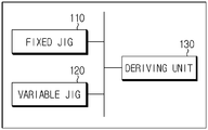
- a secondary battery evaluation apparatus comprising: a fixed jig configured to hold a secondary battery and restrict swelling of the held secondary battery, the fixed jig measuring a change in reaction force if the secondary battery according to charging and discharging cycles; a variable jig configured to hold a secondary battery and allow swelling of the held secondary battery, the variable jig measuring a reaction force and a thickness change amount of the secondary battery according to charging and discharging cycles; and a deriving unit configured to derive a relationship between the thickness change amount and the reaction force of the secondary battery by using the reaction force measured by the fixed jig and the reaction force and the thickness change amount measured by the variable jig.
- the deriving unit may derive the relationship between the thickness change amount and the reaction force of the secondary battery by using the reaction force measured by the fixed jig and the reaction force and the thickness change amount measured by the variable jig, based on the same charging and discharging cycle point.
- the deriving unit may derive the relationship between the thickness change amount and the reaction force of the secondary battery, based on a time point when the reaction force measured by the fixed jig is maximized.
- the deriving unit may derive a graph of the reaction force according to the thickness change amount of the secondary battery.
- the fixed jig may include a fixed upper jig configured to have a fixed position; a fixed lower jig located below the fixed upper jig and spaced apart from the fixed upper jig by a predetermined distance to form a retention space for the secondary battery; a fixed base member located below the fixed lower jig and spaced apart from the fixed lower jig by a predetermined distance; and a fixed measurement member interposed between the fixed base member and the fixed lower jig to measure a reaction force according to swelling of the secondary battery when the secondary battery is charged and discharged.
- variable jig may include a variable upper jig configured to be movable in a vertical direction; a variable lower jig located below the variable upper jig and spaced apart from the variable upper jig by a predetermined distance to form a retention space for the secondary battery; a variable base member located below the variable lower jig and spaced apart from the variable lower jig by a predetermined distance; a variable measurement member interposed between the variable base member and the variable lower jig to measure a reaction force according to swelling of the secondary battery when the secondary battery is charged and discharged; and an elastic member coupled to the variable upper jig to give a restoring force in a direction opposite to the movement of the variable upper jig.
- the elastic member may be located above the variable upper jig so that a bottom end thereof comes into contact with the variable upper jig and a top end thereof is coupled and fixed to the variable base member.
- variable jig may include at least one bolt, and the bolt may be configured to penetrate through the variable base member, the variable lower jig, the variable upper jig and the elastic member in order in an upper direction.
- the elastic member may include a lower plate having a lower surface that comes into contact with an upper surface of the variable upper jig, the bolt penetrating through the lower plate; a spring located above the lower plate and having a hollow through which the bolt penetrates; and an upper plate located above the spring and coupled and fixed to the bolt.
- variable upper jig may be configured so that the elastic member is exchangeable.
- variable jig may measure a reaction force and a thickness change amount of the secondary battery according to charging and discharging cycles for each case where a plurality of elastic members having different spring constants are coupled, and the deriving unit may derive the relationship between the thickness change amount and the reaction force of the secondary battery by using the reaction force and the thickness change amount for the plurality of elastic members, measured by the variable jig.
- a plurality of elastic members may be provided to the variable jig and spaced apart from each other in a horizontal direction at an upper portion of the variable upper jig.
- the relationship between the deformation amount and the reaction force (load) of the secondary battery may be effectively figured out.
- the relationship between the deformation amount and the reaction force at the end of life (EOL) at which the life span of the secondary battery ends may be derived.
- the battery module may be designed more effectively by means of the relationship obtained in this way.
- the magnitude of the structural stiffness that the battery module must have in order to prevent swelling of the secondary battery may be effectively estimated.
- the degree of deformation of the secondary battery according to the structural stiffness of the battery module may be easily predicted.
- FIG. 1 is an exploded perspective view showing a general pouch-type secondary battery.
- FIG. 2 shows the pouch-type secondary battery of FIG. 1 in an assembled state.
- FIG. 3 is a block diagram schematically showing a secondary battery evaluation apparatus according to an embodiment of the present disclosure.
- FIG. 4 is a perspective view schematically showing a fixed jig according to an embodiment of the present disclosure.
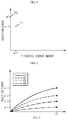
- FIG. 5 shows an example of a graph showing a measurement result of a reaction force change amount, caused by the increase of cycles due to the fixed jig according to an embodiment of the present disclosure.
- FIG. 6 is a perspective view schematically showing a variable jig according to an embodiment of the present disclosure.
- FIG. 7 shows an example of a graph showing a reaction force change amount and a thickness change amount caused by charging and discharging, measured by the variable jig according to an embodiment of the present disclosure.
- FIG. 8 is a diagram schematically showing a configuration for deriving the relationship between a thickness change amount and a reaction force of a secondary battery by a deriving unit according to an embodiment of the present disclosure.
- FIG. 9 is a graph showing a reaction force change according to the cycle in various cases where elastic members having different spring constants are coupled according to an embodiment of the present disclosure.
- FIG. 10 is a graph showing a thickness change amount according to the cycle in various cases where elastic members having different spring constants are coupled according to an embodiment of the present disclosure.
- FIG. 11 is a graph showing the relationship between the thickness change amount and the reaction force in various cases having different spring constants according to an embodiment of the present disclosure.
- FIG. 3 is a block diagram schematically showing a secondary battery evaluation apparatus according to an embodiment of the present disclosure.
- the secondary battery evaluation apparatus may include a fixed jig 110 , a variable jig 120 and a deriving unit 130 .
- the fixed jig 110 has a space for holding a secondary battery and may be configured to hold the secondary battery.
- the fixed jig 110 may be configured so that a pouch-type secondary battery is held in a horizontally lying-down form.
- the fixed jig 110 may be configured to limit swelling of the retained secondary battery. In other words, even though an internal pressure of the secondary battery increases due to the generation of gas in the secondary battery, the fixed jig 110 may be configured not to allow the secondary battery to swell. In particular, the fixed jig 110 may limit the upward and downward swelling of the retained secondary battery. In other words, the fixed jig 110 may limit the secondary battery in a lying-down form not to swell in the surface direction (the upper and lower direction in FIG. 2 ).
- the fixed jig 110 may measure the change in reaction force depending on the charging and discharging cycle of the retained secondary battery. As an example, the fixed jig 110 will be described in detail with reference to FIG. 4 .
- FIG. 4 is a perspective view schematically showing the fixed jig 110 according to an embodiment of the present disclosure.
- the fixed jig 110 may include a fixed upper jig 111 , a fixed lower jig 112 , a fixed base member 113 and a fixed measurement member 114 .
- the fixed upper jig 111 may be located above the space in which the secondary battery C is held. In other words, when the secondary battery C is accommodated in the fixed jig 110 , the fixed upper jig 111 may be located at the top of the secondary battery C. Moreover, the fixed upper jig 111 may be configured to contact a broad upper surface of the secondary battery in a face-to-face relationship.
- the fixed upper jig 111 may be configured to be fixed at a position.
- the fixed upper jig 111 may be fixed in the vertical direction without moving in the vertical direction.
- the fixed upper jig 111 may maintain its position even though the secondary battery C swells due to charge and discharge of the secondary battery C. Due to the fixed position of the fixed upper jig 111 , the fixed jig 110 may limit upward swelling of the secondary battery C.
- the fixed lower jig 112 may be located below the fixed upper jig 111 .
- the fixed lower jig 112 may be spaced apart from the fixed upper jig 111 by a predetermined distance to form a space for retaining the secondary battery, namely a space for accommodating the secondary battery.
- the secondary battery may be accommodated in the retention space between the fixed upper jig 111 and the fixed lower jig 112 .
- a pouch-type secondary battery may be placed between the fixed upper jig 111 and the fixed lower jig 112 in a horizontally lying-down form in which two large surfaces are oriented upward and downward.
- the fixed lower jig 112 may be configured to contact a broad bottom surface of the secondary battery in a face-to-face relationship.
- the fixed base member 113 may be located below the fixed lower jig 112 . In addition, the fixed base member 113 may be spaced apart from the fixed lower jig 112 by a predetermined distance.
- the fixed base member 113 may be coupled with the fixed upper jig 111 and the fixed lower jig 112 .
- the fixed upper jig 111 , the fixed lower jig 112 and the fixed base member 113 may be coupled to each other in such a manner that a plurality of fastening members such as bolts L penetrates therethrough.
- the fixed base member 113 and the fixed upper jig 111 may be coupled so that a separation distance therebetween does not exceed a certain level.
- the upper and lower ends of four bolts L are protruded at the top end of the fixed upper jig 111 and the bottom end of the fixed base member 113 , respectively, and nuts N may be fastened to the protruding portions.
- the fixed upper jig 111 and the fixed base member 113 may not be further apart from each other based on the portion where the nuts N are fastened.
- the fixed lower jig 112 may be configured to be movable in the vertical direction with the bolts passing therethrough.
- at least one hole may be formed in the fixed lower jig 112 , and a bolt L passing through the fixed upper jig 111 and the fixed base member 113 may pass through the hole.
- the fixed lower jig 112 may be configured to be movable up and down along the bolt in a state where the bolt passes through the fixed lower jig 112 .
- a fixed measurement member 114 may be positioned below the fixed lower jig 112 to prevent the fixed lower jig 112 from moving downward.
- the fixed measurement member 114 may be interposed in the space between the fixed base member 113 and the fixed lower jig 112 . Also, the fixed measurement member 114 may measure the reaction force according to the swelling of the secondary battery. As the secondary battery is charged and discharged, gas may be generated inside the secondary battery, and thus the internal pressure may increase. At this time, the fixed measurement member 114 may measure the load applied to the fixed lower jig 112 due to the increase of the internal pressure as the reaction force.
- the fixed lower jig 112 may move downward and press the fixed measurement member 114 located thereunder. Then, the fixed measurement member 114 may measure the reaction force according to the degree of pressurization and quantify the same. At this time, the fixed measurement member 114 may be configured not to change its thickness even though the fixed measurement member 114 is pressed. In addition, by this, even though the internal pressure of the secondary battery increases, the fixed lower jig 112 may not move substantially downward. Thus, in this case, the thickness of the secondary battery may not change within the fixed jig 110 .
- the fixed measurement member 114 may be implemented using a load cell.
- the load cell may be deformed, for example, compressed, by the reaction force applied to the fixed lower jig 112 , and the load cell may quantify the degree of deformation to measure the applied pressure.
- FIG. 5 shows an example of a graph showing a measurement result of a reaction force change amount caused by the increase of cycles, using the fixed jig 110 according to an embodiment of the present disclosure.
- the x-axis represents a charging and discharging cycle and may be in the unit of ‘number’.
- the y-axis represents a reaction force and may be in the unit of ‘kgf’.
- the secondary battery may further swell as charging and discharging are repeated, namely as the charging and discharging cycle progresses. Then, the reaction force (load) measured by the fixed measurement member 114 of the fixed jig 110 may continue to increase.
- the fixed measurement member 114 of the fixed jig 110 may periodically or non-periodically measure the reaction force according to swelling several times. In this case, the reaction force measured by the fixed measurement member 114 of the fixed jig 110 may be obtained in a graph form as shown in FIG. 5 .
- the fixed upper jig 111 , the fixed lower jig 112 and/or the fixed base member 113 may be formed in a flat plate shape as shown in the figure.
- the vertical size of the jig may be reduced, and the jig may stably and uniformly contact the secondary battery through a broad and flat surface.
- the secondary battery evaluation apparatus according to the present disclosure may evaluate a pouch-type secondary battery, and the pouch-type secondary battery may be formed into a substantially rectangular flat shape with two large surfaces. At this time, two broad surfaces of the pouch-type secondary battery may contact the lower surface of the fixed upper jig 111 and the upper surface of the fixed lower jig 112 , and in this case, a broader contact area may be formed.
- the variable jig 120 may be configured to have a space for holding a secondary battery to hold the secondary battery therein. Moreover, the variable jig 120 may be configured so that a pouch-type secondary battery is held in a horizontally lying state.
- variable jig 120 may be configured to allow swelling of the retained secondary battery. Moreover, the variable jig 120 may be configured to allow upward swelling of the secondary battery. In other words, unlike the fixed jig 110 , the variable jig 120 may be configured to allow the secondary battery to swell in a surface direction, particularly in an upward direction, when gas is generated in the secondary battery to increase the internal pressure.
- the variable jig 120 may measure the reaction force and the thickness change amount according to the charging and discharging cycle of the retained secondary battery. In particular, since the variable jig 120 allows swelling of the secondary battery, it is possible to measure the thickness change amount of the secondary battery together with the reaction force by the secondary battery. An example of the variable jig 120 will be described in more detail with reference to FIG. 6 .
- FIG. 6 is a perspective view schematically showing the variable jig 120 according to an embodiment of the present disclosure.
- variable jig 120 may include a variable upper jig 121 , a variable lower jig 122 , a variable base member 123 , a variable measurement member 124 and an elastic member 125 .
- variable upper jig 121 may be located above the space in which the secondary battery is held. In other words, when the secondary battery is accommodated in the variable jig 120 , the variable upper jig 121 may be located at the top of the secondary battery.
- variable upper jig 121 may be configured to be movable.
- the variable upper jig 121 may be configured to be movable in the vertical direction.
- the variable upper jig 121 may move in an upper direction.
- the variable upper jig 121 may move to the upper direction as indicated by the arrow E, depending on the degree of swelling.
- the variable jig 120 may allow upward swelling of the secondary battery.
- the variable lower jig 122 may be located below the variable upper jig 121 .
- the variable lower jig 122 may be spaced apart from the variable upper jig 121 by a predetermined distance to form a space for holding the secondary battery.
- the secondary battery may be accommodated in the holding space between the variable upper jig 121 and the variable lower jig 122 .
- a pouch-type secondary battery may be placed between the variable upper jig 121 and the variable lower jig 122 in a horizontally lying state so that two broad surfaces are oriented upward and downward.
- the variable base member 123 may be located below the variable lower jig 122 .
- the variable base member 123 may be configured to be spaced apart from the variable lower jig 122 by a predetermined distance.
- variable base member 123 may be coupled with the variable upper jig 121 and the variable lower jig 122 .
- the variable upper jig 121 , the variable lower jig 122 and the variable base member 123 may be coupled to each other in such a manner that a plurality of fastening members such as bolts L penetrates therethrough.
- variable lower jig 122 may be configured to be movable in the vertical direction in a state where the bolts L penetrate therethrough.
- six holes are formed in the variable lower jig 122 , and bolts L passing through the variable upper jig 121 and the variable base member 123 may pass through the holes.
- the variable upper jig 121 may move in the upward direction
- the variable lower jig 122 may move in the downward direction.
- the hole may be formed at an edge of the variable lower jig, rather than at a center thereof. In this configuration of the present disclosure, it is possible to secure a large space for placing the secondary battery at the top of the variable lower jig and to prevent the space of placing the secondary battery from being restricted by the bolt penetrating through the hole.
- variable measurement member 124 may be interposed in the space between the variable base member 123 and the variable lower jig 122 . Also, the variable measurement member 124 may measure the reaction force caused by the swelling of secondary battery C. In other words, if gas is generated in the secondary battery so that the secondary battery swells, the variable measurement member 124 may measure the magnitude of the pressing force caused by the swelling.
- variable lower jig 122 may tend to move downward and press the variable measurement member 124 located below. If so, the variable measurement member 124 may measure the reaction force according to the degree of pressurization and quantify the same.
- the variable measurement member 124 may be implemented using a load cell, like the fixed measurement member 114 . Also, the variable measurement member 124 may be configured such that its thickness does not change. Thus, even though the secondary battery swells, the variable lower jig 122 may substantially not move downward.
- variable measurement member 124 may measure the thickness change amount according to the charging and discharging cycle of the secondary battery. In other words, if gas is generated inside the secondary battery to increase the volume, the variable measurement member 124 may measure the degree of thickness deformation due to the swelling of the secondary battery. For example, if the secondary battery swells so that the variable upper jig 121 moves upward and the lower jig 122 moves downward, the variable measurement member 124 may measure the thickness change amount of the secondary battery by measuring a distance between the variable upper jig 121 and the variable lower jig 122 .
- the elastic member 125 may be coupled to the variable upper jig 121 .
- the elastic member 125 may have a structure or material having elasticity.
- the elastic member 125 may be formed with a metal spring.
- the elastic member 125 may be made of a rubber material.
- the elastic member 125 may be configured to form a restoring force in a direction opposite to the movement of the variable upper jig 121 .
- a restoring force to restore in the opposite direction namely in the downward direction, may be formed.
- the stiffness or elasticity of a structure surrounding the secondary battery may be similarly implemented.
- the secondary battery may be surrounded by a case or cartridge, and the case or the cartridge may have a certain level of elasticity.
- the case and the cartridge may be implemented using the elastic member 125 , and thus in the actual battery module, the swelling characteristic of the secondary battery may be more accurately and easily figured out in consideration of the rigidity or the like of surrounding structures.
- the elastic member 125 may be located above the variable upper jig 121 .
- the elastic member 125 may be located at the top of the variable upper jig 121 .
- the bottom end of the elastic member 125 may be configured to contact the variable upper jig 121 .
- the upper jig 121 moves upward due to swelling of the secondary battery, the bottom end of the elastic member 125 may move upward.
- the top end of the variable upper jig 121 is configured to be movable, when the variable upper jig 121 moves upward, the top end of the elastic member 125 may also move upward, and thus the elastic member 125 may not be appropriately compressed.
- the top end of the elastic member 125 is preferably fixed at a constant position.
- the top end of the elastic member 125 may be coupled and fixed to the variable base member 123 . If the top end of the elastic member 125 is coupled and fixed to the variable base member 123 as described above, the distance between the elastic member 125 and the variable base member 123 may be kept constant. Thus, even though the secondary battery swells so that the variable upper jig 121 moves upward and the bottom end of the elastic member 125 moves upward, the top end of the elastic member 125 may be fixed at a certain position. Thus, as the distance between the top end and the bottom end of the elastic member 125 becomes shorter, the elastic member 125 may be compressed to increase the elastic energy, and a force to restore in the opposite direction may be formed.
- the top end of the elastic member 125 need not be fixed to a structure other than the variable jig 120 .
- the variable jig 120 may be configured independently, which may allow free movement of the variable jig 120 and reduce the volume of the variable jig 120 .
- the variable jig 120 may include at least one bolt.
- the variable jig 120 may include a plurality of bolts N elongating in a vertical direction.
- the bolts may be configured to sequentially pass through the variable base member 123 , the variable lower jig 122 , the variable upper jig 121 and the elastic member 125 from the lower side to the upper side.
- variable base member 123 various components included in the variable jig 120 may be coupled to each other by using a single element (bolt). Moreover, since the bolt is configured to penetrate through these components, respectively, an element for coupling them is substantially not exposed, and the overall volume may be reduced.
- the elastic member 125 may have a lower plate, a spring and an upper plate.
- variable jig 120 may include six elastic members 125 , and each elastic member 125 may have a lower plate F 1 , a spring S and an upper plate F 2 .
- the lower plate F 1 may be configured in the form of a flat plate, and the lower surface of the lower plate F 1 may contact the upper surface of the variable upper jig 121 .
- a bolt may penetrate through the lower plate.
- the spring S is placed on the upper portion of the lower plate and may be made of, for example, a metal material.
- the spring may be formed in a spiral shape so that a bolt penetrates through its hollow.
- the upper plate F 2 may be configured in the form of a flat plate and positioned at the upper portion of the spring.
- the upper plate may be coupled and fixed to the bolt.
- the upper plate may be coupled and fixed to the bolt in such a manner that the bolt passing through the variable base member 123 , the variable lower jig 122 , the variable upper jig 121 , the lower plate and the spring penetrates through the upper plate to expose a top end of the bolt is exposed upwards, and a nut N is coupled to the exposed portion of the bolt.
- the upper portion of the spring may be stably fixed by the upper plate. Also, in this case, when the variable upper jig 121 moves upward due to swelling of the secondary battery, the pressing force applied to the spring may be uniformly transmitted to the lower portion of the spring by the lower plate. Thus, it is possible to restrict irregular detachment or deformation of the spring by the pressing force when the secondary battery swells.
- FIG. 7 shows an example of a graph showing a reaction force change amount and a thickness change amount caused by charging and discharging, measured by the variable jig 120 according to an embodiment of the present disclosure.
- the x-axis represents a charging and discharging cycle and may be in the unit of ‘number’.
- the y-axis represents a reaction force or a thickness change amount and may be in the unit of ‘kg’ or ‘mm’.
- the reaction force measured by the variable measurement member 124 of variable jig 120 may also continue to increase as the secondary battery performs charging and discharging.
- the variable measurement member 124 of the variable jig 120 may also periodically or non-periodically measure the reaction force caused by the swelling several times so that the changing tendency of the reaction force may be obtained using a single line such as a curve as indicated by A 1 in FIG. 7 .
- the secondary battery may swell as gas is generated therein due to repeated charging and discharging.
- the thickness of the secondary battery may gradually increase as the charging and discharging cycle increases.
- the deformation amount, namely the thickness change amount, of the secondary battery measured by the variable jig 120 may be expressed with a curve gradually increasing with time, as indicated by A 2 in FIG. 7 .
- the deriving unit 130 may derive the relationship between the thickness change amount and the reaction force of the secondary battery by using the reaction force measured by the fixed jig 110 and the reaction force and the thickness change amount measured by the variable jig 120 .
- the deriving unit 130 may derive the relationship between the thickness change amount and the reaction force of the secondary battery by using a reaction force at a predetermined time point in the reaction force measured by the fixed jig 110 and a reaction force and a the thickness change amount at a predetermined time point in the reaction force and the thickness change amount measured by the variable jig 120 .
- the deriving unit 130 may derive the relationship between the thickness change amount and the reaction force of the secondary battery based on the same charging and discharging cycle point.
- the deriving unit 130 may derive the relationship between the thickness change amount and the reaction force of the secondary battery by using the reaction force measured by the fixed jig 110 and the reaction force and the thickness change amount measured by the variable jig 120 at the same charging and discharging cycle point.
- the deriving unit 130 may obtain a y coordinate (a0) at a time point T 1 on the graph of the reaction force of the secondary battery obtained by the fixed jig 110 .
- the y coordinate (a0) may be regarded as the reaction force of the secondary battery at T 1 .
- the deriving unit 130 may obtain a y coordinate (a11) at the time point T 1 on the graph A 1 of the reaction force obtained by the variable jig 120 . Also, the deriving unit 130 may obtain a y coordinate (b11) at the time point T 1 on the graph B 1 of the deformation amount of the secondary battery obtained by the variable jig 120 .
- the deriving unit 130 may derive the relationship between the thickness change amount and the reaction force of the secondary battery by using the reaction force and the deformation amount (the thickness change amount) obtained at a predetermined time by the fixed jig 110 and the variable jig 120 .
- the deriving unit 130 may derive the relationship between the thickness change amount and the reaction force of the secondary battery based on a time point at which the reaction force measured by the fixed jig 110 is maximized.
- the time point at which the reaction force of the battery reaches maximum may be T 1 .
- the cycle point T 1 at which the reaction force of the battery becomes maximum by the fixed jig 110 is determined, the reaction force and the thickness change amount measured by the variable jig 120 may be extracted based on the time point T 1 .
- the life span of the secondary battery may be roughly predicted or determined when the battery is manufactured.
- the time point for predicting the reaction force and the thickness change amount may be determined based on the predicted or predetermined life span.
- the time point T 1 may be set to 5000 cycles for the corresponding secondary battery in the graphs of FIGS. 5 and 7 .
- the reaction force of the secondary battery by the fixed jig 110 and the reaction force and the thickness change amount of the secondary battery by the variable jig 120 at the time point of 5000 cycles may be extracted.
- the deriving unit 130 may derive a graph of the reaction force according to the thickness change amount of the secondary battery.
- the deriving unit 130 may derive a graph on a coordinate plane in which the deformation amount, namely the thickness change amount, of the secondary battery is x axis x-axis, and the reaction force of the secondary battery is y-axis.
- the deriving unit 130 may derive a graph of the deformation amount and the reaction force of the secondary battery by using the reaction force at a predetermined time point obtained by the fixed jig 110 and the reaction force and the deformation amount at a predetermined time point obtained by the variable jig 120 .
- FIG. 8 is a diagram schematically showing a configuration for deriving the relationship between a deformation amount and a reaction force of a secondary battery by the deriving unit 130 according to an embodiment of the present disclosure.
- the deriving unit 130 may set a coordinate plane where the x-axis represents the thickness change amount of the secondary battery and the y-axis represents the reaction force of the secondary battery.
- the x-axis may be in the unit of length, for example ‘mm’
- the y-axis may be in the unit of force or weight, for example ‘kgf’.
- the deriving unit 130 may represent the reaction force at the time point T 1 obtained by the fixed jig 110 by using a single point. For example, in the graph of FIG. 5 , a0 that is the reaction force at the time point T 1 may become a y coordinate. Also, since there is substantially no thickness change amount of the battery at the fixed jig 110 , the x coordinate at this time may be 0 (zero). Thus, the deriving unit 130 may obtain a coordinate point P 0 (0, a0) by the fixed jig 110 . In other words, the deriving unit 130 may input the reaction force obtained by the fixed jig 110 on the coordinate plane of the deformation amount and the reaction force as a y-intercept.
- the deriving unit 130 may represent at least one point in the coordinate plane by using the deformation amount and the reaction force at the time point T 1 obtained by the variable jig 120 .
- a single point P 1 having a coordinate (b11, a11) may be obtained by setting b11 that is the thickness change amount (the deformation amount) at the time point T 1 as an x coordinate and a11 that is the reaction force at the time point T 1 as a y coordinate.
- the deriving unit 130 may obtain a single line.
- the deriving unit 130 may obtain a single graph by connecting the points obtained by the fixed jig 110 and the variable jig 120 to each other.
- variable jig 120 may include an elastic member 125 , and the elastic member 125 may be configured to be exchangeable.
- variable upper jig 121 is coupled to the elastic member 125 , and the variable upper jig 121 may be configured so that the elastic member 125 is exchangeable.
- variable jig 120 may be configured so that the elastic member 125 is exchanged with another kind of elastic member 125 .
- the variable jig 120 may be configured so that the elastic member 125 is exchanged with an elastic member 125 having a different spring constant.
- the variable upper jig 121 and the elastic member 125 included in the variable jig 120 may be configured to be detachable and fastenable by being coupled to each other with a hooking structure.
- the variable upper jig 121 and the elastic member 125 may be configured to be detachable and fastenable by being coupled to each other with a fitting structure.
- an upper portion of the variable upper jig 121 may have an insertion groove formed in a size and shape corresponding to a lower outer shape of the elastic member 125 , and a lower portion of the elastic member 125 may be inserted into the insertion groove.
- the elastic member 125 may be in the form of a spring made of metal and having a spiral shape.
- different kinds of elastic bodies having different spring constants may be coupled to the variable upper jig 121 as a substitution.
- the elastic member 125 may be positioned at the top of the variable upper jig 121 and coupled to the variable upper jig 121 . In this case, the elastic member 125 may be exchanged more easily.
- variable jig 120 may measure the reaction force and the thickness change amount according to the charging and discharging cycle of the secondary battery, respectively for each case where each elastic member 125 is coupled.
- FIG. 9 is a graph showing a reaction force change according to the cycle in various cases where elastic members having different spring constants are coupled according to an embodiment of the present disclosure
- FIG. 10 is a graph showing a thickness change amount according to the cycle in various cases where elastic members 125 having different spring constants are coupled according to an embodiment of the present disclosure.
- the x-axis represents a charging and discharging cycle and may be in the unit of ‘number’.
- the y-axis represents a reaction force and may be in the unit of ‘kgf’.
- the x-axis represents a charging and discharging cycle and may be in the unit of ‘number’.
- the y-axis represents a thickness change amount and may be in the unit of ‘mm’.
- a reaction force graph A 1 and a thickness change amount graph B 1 are shown in the same form as shown in FIG. 7 .
- the reaction force of the graph A 1 and the thickness change amount of the graph B 1 at the time point T 1 may be a 11 and b 11 , respectively.
- a coordinate point (b 11 , a 11 ) may be obtained (P 1 ), identical to the case of FIG. 8 .
- the reaction force graph may be obtained in the form of a graph A 2 having a lower reaction force than the graph A 1 .
- the thickness change amount of the battery may increase.
- the deformation amount graph may be obtained in the form of a graph B 2 having a higher thickness change amount in comparison to the graph B 1 .
- the thickness change amount and the reaction force at the time point T 1 may be derived as b12 and a12.
- a coordinate point (b12, a12) may be obtained on the coordinate plane of the thickness change amount and the reaction force (P 2 ).
- the reaction force may become smaller and the thickness change amount may become larger.
- the thickness change amount value and the reaction force value at the time point T 1 may be derived as b13 and a13.
- a coordinate point (b13, a13) may be obtained on the coordinate plane of the thickness change amount and the reaction force (P 3 ).
- the thickness change amount and the reaction force at the time point T 1 may be derived as b14 and a14.
- a coordinate point (b14, a14) may be obtained on the coordinate plane of the thickness change amount and the reaction force (P 4 ).
- the graphs of A 1 to A 4 and B 1 to B 4 may be respectively obtained by varying the spring constant corresponding to the rigidity of the module case or the cartridge surrounding the secondary battery in the battery module.
- the graphs of FIGS. 9 to 10 may be derived by changing the spring constant of the elastic member to 50 kgf, 100 kgf, 200 kgf, and 10,000 kgf.
- the deriving unit 130 may obtain the graph of the deformation amount and the reaction force by using the coordinate points. In other words, if the reaction force and the thickness change amount according to the charging and discharging cycle are measured by the variable jig 120 for every case where a plurality of elastic members 125 having different spring constants are coupled, the deriving unit 130 may derive the relationship between the deformation amount and the reaction force of the secondary battery by using the measurement results.
- FIG. 11 is a graph showing the relationship between the deformation amount and the reaction force in various cases having different spring constants according to an embodiment of the present disclosure.
- the x-axis may be in the unit of length, for example ‘mm’
- the y-axis may be in the unit of force or weight, for example ‘kgf’.
- the deriving unit 130 may represent one point (P 0 ) on the y-axis by using the coordinate point (0, a0) obtained by the fixed jig 110 in the embodiment of FIG. 5 , on the coordinate plane of the deformation amount and the reaction force. Also, the deriving unit 130 may display four coordinate points (P 1 , P 2 , P 3 , P 4 ) obtained by the variable jig 120 while varying the spring constant in the embodiment of FIGS. 9 and 10 , on the coordinate plane.
- the deriving unit 130 may obtain a single line V by using the five points (P 0 to P 5 ) displayed as above.
- the deriving unit 130 may derive a single curve V by using the five points.
- the curve V derived as above may be a graph showing the relationship between the deformation amount and the reaction force of the secondary battery. Further, the deriving unit 130 may obtain a more precise curve when there are more coordinate points of cases having different spring constants.
- the curve V of the deformation amount and the reaction force obtained as above may be used in designing a battery module including a plurality of secondary batteries.
- the curve of the deformation amount and the reaction force may be obtained by using the spring constant of the cartridge.
- the rigidity of the cartridge may be appropriately designed.
- the deformation amount of the secondary battery may be easily predicted or controlled depending on the rigidity of the cartridge.
- the battery module includes a plurality of secondary batteries that are accommodated in a single module case
- the curve of the deformation amount and the reaction force of the entire module may be obtained.
- the rigidity of the module case may be designed within an appropriate range.
- the deformation amount of the secondary battery may be controlled by means of the rigidity or structure of the module case.
- the charging and discharging cycle test conditions for example test temperature, C-rate, SOC range and the like, may be set identically.
- the variable jig includes various kinds of elastic members with different spring constants, it is recommended that the charging and discharging cycle test conditions are set identically.
- a plurality of elastic members 125 may be provided to the variable jig 120 .
- six elastic members 125 may be provided at the upper portion of the variable jig 120 .
- the plurality of elastic members 125 may be spaced from the upper portion of the variable upper jig 121 by a predetermined distance in the horizontal direction.
- the plurality of elastic members 125 may be positioned at corners of the variable upper jig 121 at the upper portion of the variable upper jig 121 and be spaced apart from each other by a predetermined distance.
- the bolt L may easily avoid the secondary battery C.
- the bolt L passing through the elastic member may pass through both the variable upper jig 121 and the variable lower jig 122 , and here, the secondary battery is located between the variable upper jig 121 and the variable lower jig 122 .
- the bolt L is located at the corner of the variable upper jig 121 and the lower jig 122 , the space for accommodating the secondary battery may be secured widely between the variable upper jig 121 and the variable lower jig 122 .
- the reaction force caused by the swelling of the secondary battery may be uniformly formed by the elastic member 125 since the elastic force by the elastic member 125 is not concentrated on a specific portion of the variable upper jig 121 or the secondary battery located thereunder but spreads widely.
- variable upper jig 121 and/or the variable lower jig 122 may be configured not to be easily bent by an external force, like a rigid body.
- the variable upper jig 121 and/or the variable lower jig 122 may be configured not to be bent by the swelling of the secondary battery or the pressing of the elastic member 125 .
- the force caused by the swelling of the secondary battery or to the pressing of the elastic member 125 may be uniformly transferred to the variable upper jig 121 or the variable lower jig 122 , thereby enabling more accurate measurement of the deformation amount and the reaction force.
Abstract
Description
-
- 110: fixed jig
- 111: fixed upper jig, 112: fixed lower jig, 113: fixed base member, 114: fixed measurement member
- 120: variable jig
- 121: variable upper jig, 122: variable lower jig, 123: variable base member, 124: variable measurement member, 125: elastic member
- 130: deriving unit
Claims (12)
Applications Claiming Priority (3)
| Application Number | Priority Date | Filing Date | Title |
|---|---|---|---|
| KR1020170011228A KR102070684B1 (en) | 2017-01-24 | 2017-01-24 | Secondary battery evaluation apparatus |
| KR10-2017-0011228 | 2017-01-24 | ||
| PCT/KR2018/001008 WO2018139833A1 (en) | 2017-01-24 | 2018-01-23 | Secondary battery evaluation device |
Publications (2)
| Publication Number | Publication Date |
|---|---|
| US20190094003A1 US20190094003A1 (en) | 2019-03-28 |
| US10845181B2 true US10845181B2 (en) | 2020-11-24 |
Family
ID=62979384
Family Applications (1)
| Application Number | Title | Priority Date | Filing Date |
|---|---|---|---|
| US16/080,619 Active 2038-05-21 US10845181B2 (en) | 2017-01-24 | 2018-01-23 | Secondary battery evaluation apparatus |
Country Status (4)
| Country | Link |
|---|---|
| US (1) | US10845181B2 (en) |
| KR (1) | KR102070684B1 (en) |
| CN (1) | CN208013387U (en) |
| WO (1) | WO2018139833A1 (en) |
Cited By (1)
| Publication number | Priority date | Publication date | Assignee | Title |
|---|---|---|---|---|
| US11561083B2 (en) * | 2017-11-06 | 2023-01-24 | Lg Energy Solution, Ltd. | Secondary battery and apparatus and method for measuring dimension of secondary battery |
Families Citing this family (19)
| Publication number | Priority date | Publication date | Assignee | Title |
|---|---|---|---|---|
| CN109765356A (en) * | 2019-01-18 | 2019-05-17 | 江苏医联生物科技有限公司 | A kind of protein-chip fluorescence detection method |
| KR102152572B1 (en) | 2019-03-22 | 2020-09-07 | 영남대학교 산학협력단 | System of sensing swelling of secondary battery |
| KR20210062426A (en) | 2019-11-21 | 2021-05-31 | 주식회사 엘지에너지솔루션 | Parallel High Rigidity Spring Jig with improved it's nonlinearity |
| KR20210117829A (en) * | 2020-03-20 | 2021-09-29 | 주식회사 엘지에너지솔루션 | Apparatus for examining battery swelling |
| KR20210138883A (en) | 2020-05-13 | 2021-11-22 | 주식회사 엘지에너지솔루션 | Cell jig for detecting swelling of battery cell and method for measuring swelling of the battery cell using the same |
| KR20220013101A (en) | 2020-07-24 | 2022-02-04 | 주식회사 엘지에너지솔루션 | Cell jig for measuring swelling of battery cell including ultrasonic sensor and method for measuring swelling of the battery cell using the same |
| KR20220013847A (en) * | 2020-07-27 | 2022-02-04 | 주식회사 엘지에너지솔루션 | Pressure measurement unit and apparatus for testing battery |
| KR20220015551A (en) * | 2020-07-31 | 2022-02-08 | 주식회사 엘지에너지솔루션 | Cell jig including film type pressure sensor and method for measuring swelling of the battery cell using the same |
| KR20220042677A (en) * | 2020-09-28 | 2022-04-05 | 주식회사 엘지에너지솔루션 | Battery cell jig with spacer, battery cell volume measuring device including the same and battery cell volume measuring method using the same |
| AT524291B1 (en) * | 2020-10-01 | 2022-10-15 | Avl List Gmbh | DEVICE FOR TESTING AT LEAST ONE BATTERY CELL |
| KR20220045440A (en) | 2020-10-05 | 2022-04-12 | 주식회사 엘지에너지솔루션 | Battery module including buffer pad for preventing damage to battery cell, and battery pack including the same |
| KR20220058049A (en) * | 2020-10-30 | 2022-05-09 | 주식회사 엘지에너지솔루션 | Battery cell jig with spacer laminate, battery cell volume measuring device including the same and battery cell volume measuring method using the same |
| CN112731152A (en) * | 2020-12-21 | 2021-04-30 | 天津力神电池股份有限公司 | Power battery full-life cycle constant pressure testing tool and method |
| CN112749497B (en) * | 2020-12-22 | 2022-12-16 | 厦门海辰储能科技股份有限公司 | Method for predicting expansion force of lithium ion battery module or battery pack |
| CN112864464B (en) * | 2021-01-08 | 2022-06-24 | 国联汽车动力电池研究院有限责任公司 | Method and device for improving cycle performance of soft package lithium ion battery |
| KR20230009230A (en) * | 2021-07-08 | 2023-01-17 | 주식회사 엘지에너지솔루션 | Battery management system, battery pack, electric vehicle, and battery management method |
| CN113725505B (en) * | 2021-08-03 | 2023-06-02 | 天津市捷威动力工业有限公司 | Module expansion safety assessment method |
| CN114509197B (en) * | 2022-02-17 | 2022-09-30 | 中国科学技术大学 | Stress change in-situ testing device for soft package battery |
| KR102524549B1 (en) * | 2022-11-29 | 2023-04-20 | 한국산업기술시험원 | Swelling force measuring apparatus |
Citations (10)
| Publication number | Priority date | Publication date | Assignee | Title |
|---|---|---|---|---|
| KR20080074240A (en) | 2007-02-08 | 2008-08-13 | 주식회사 엘지화학 | Secondary battery inspection device |
| KR20080112003A (en) | 2007-06-20 | 2008-12-24 | 현대모비스 주식회사 | Tester for a air-bag module |
| US7511456B2 (en) * | 2005-05-02 | 2009-03-31 | Lg Chem, Ltd. | Middle or large-sized battery pack having a plurality of battery cells in a compact structure |
| KR20140137562A (en) | 2013-05-23 | 2014-12-03 | 주식회사 엘지화학 | Jig for Measuring of Battery Thickness and Method for Measuring of Battery Thickness Using the Same |
| KR20140140431A (en) | 2013-05-29 | 2014-12-09 | 주식회사 엘지화학 | Device for detecting inner pressure of secondary battery, and method for detecting inner pressure of secondary battery by using the same |
| KR20150035268A (en) | 2013-09-27 | 2015-04-06 | 주식회사 엘지화학 | Device for detecting inner pressure of secondary battery, and method for detecting inner pressure of secondary battery by using the same |
| US20150098749A1 (en) * | 2012-04-20 | 2015-04-09 | Zf Friedrichshafen Ag | Ball and socket joint for a vehicle |
| KR20150049521A (en) | 2013-10-30 | 2015-05-08 | 주식회사 엘지화학 | Apparatus for measuring a size of battery pack |
| KR20160063278A (en) | 2014-11-26 | 2016-06-03 | 주식회사 엘지화학 | Apparatus and Method of Measuring Thickness of Secondary Battery Cell |
| US20170244088A1 (en) * | 2016-02-18 | 2017-08-24 | Saft | Compensation system for swelling of electrochemical cells |
Family Cites Families (2)
| Publication number | Priority date | Publication date | Assignee | Title |
|---|---|---|---|---|
| KR20150045242A (en) * | 2013-10-18 | 2015-04-28 | 주식회사 엘지화학 | Safety experimental system for the secondary battery and transparent jig applied for the same |
| KR101692414B1 (en) * | 2016-06-20 | 2017-01-03 | 주식회사 엘지화학 | Device for detecting inner pressure of secondary battery, and method for detecting inner pressure of secondary battery by using the same |
-
2017
- 2017-01-24 KR KR1020170011228A patent/KR102070684B1/en active IP Right Grant
-
2018
- 2018-01-23 WO PCT/KR2018/001008 patent/WO2018139833A1/en active Application Filing
- 2018-01-23 US US16/080,619 patent/US10845181B2/en active Active
- 2018-01-24 CN CN201820122461.XU patent/CN208013387U/en active Active
Patent Citations (12)
| Publication number | Priority date | Publication date | Assignee | Title |
|---|---|---|---|---|
| US7511456B2 (en) * | 2005-05-02 | 2009-03-31 | Lg Chem, Ltd. | Middle or large-sized battery pack having a plurality of battery cells in a compact structure |
| KR20080074240A (en) | 2007-02-08 | 2008-08-13 | 주식회사 엘지화학 | Secondary battery inspection device |
| KR20080112003A (en) | 2007-06-20 | 2008-12-24 | 현대모비스 주식회사 | Tester for a air-bag module |
| US20150098749A1 (en) * | 2012-04-20 | 2015-04-09 | Zf Friedrichshafen Ag | Ball and socket joint for a vehicle |
| KR20140137562A (en) | 2013-05-23 | 2014-12-03 | 주식회사 엘지화학 | Jig for Measuring of Battery Thickness and Method for Measuring of Battery Thickness Using the Same |
| KR20140140431A (en) | 2013-05-29 | 2014-12-09 | 주식회사 엘지화학 | Device for detecting inner pressure of secondary battery, and method for detecting inner pressure of secondary battery by using the same |
| KR20150035268A (en) | 2013-09-27 | 2015-04-06 | 주식회사 엘지화학 | Device for detecting inner pressure of secondary battery, and method for detecting inner pressure of secondary battery by using the same |
| KR20150049521A (en) | 2013-10-30 | 2015-05-08 | 주식회사 엘지화학 | Apparatus for measuring a size of battery pack |
| KR20160063278A (en) | 2014-11-26 | 2016-06-03 | 주식회사 엘지화학 | Apparatus and Method of Measuring Thickness of Secondary Battery Cell |
| US20170074634A1 (en) * | 2014-11-26 | 2017-03-16 | Lg Chem, Ltd. | Device and method for measuring thickness of secondary battery cell |
| US10184778B2 (en) * | 2014-11-26 | 2019-01-22 | Lg Chem, Ltd. | Device and method for measuring thickness of secondary battery cell |
| US20170244088A1 (en) * | 2016-02-18 | 2017-08-24 | Saft | Compensation system for swelling of electrochemical cells |
Non-Patent Citations (1)
| Title |
|---|
| International Search Report for PCT/KR2018/001008 (PCT/ISA/210) dated May 1, 2018. |
Cited By (1)
| Publication number | Priority date | Publication date | Assignee | Title |
|---|---|---|---|---|
| US11561083B2 (en) * | 2017-11-06 | 2023-01-24 | Lg Energy Solution, Ltd. | Secondary battery and apparatus and method for measuring dimension of secondary battery |
Also Published As
| Publication number | Publication date |
|---|---|
| KR102070684B1 (en) | 2020-01-29 |
| CN208013387U (en) | 2018-10-26 |
| KR20180087040A (en) | 2018-08-01 |
| US20190094003A1 (en) | 2019-03-28 |
| WO2018139833A1 (en) | 2018-08-02 |
Similar Documents
| Publication | Publication Date | Title |
|---|---|---|
| US10845181B2 (en) | Secondary battery evaluation apparatus | |
| US11561152B2 (en) | Apparatus for predicting deformation of battery module | |
| US20210344057A1 (en) | Battery module having swelling gauge, and battery pack comprising same | |
| CN102074728B (en) | The method of battery pack, vehicle, reinforcing battery pack and the method for formation battery pack | |
| CN110998902B (en) | Battery module and method of manufacturing the same | |
| EP2439807A1 (en) | Rechargeable battery | |
| KR101359902B1 (en) | Jig for Charging and Discharging of Battery Cell | |
| CN108604655B (en) | Belt for battery module, battery module including belt, and jig for compressing belt | |
| KR20160110167A (en) | Battery pack spacer and battery pack | |
| EP3883007A1 (en) | A battery module, a method for assembling a battery module and a vehicle including a battery pack comprising at least one battery module | |
| KR20200049123A (en) | Battery module including Temperature Measurement Device | |
| US20200044293A1 (en) | Apparatus and Method for Testing End Plate | |
| JP6361969B2 (en) | Storage element and storage element module | |
| US20230129671A1 (en) | Battery pack, electronic device and vehicle | |
| CN113725505A (en) | Module expansion safety assessment method | |
| KR101487209B1 (en) | Charging and Discharging Device of Battery Cell | |
| KR20210081611A (en) | A pouch for analyzing the swelling characteristics of the battery cells and methods of analyzing the battery cells using the same | |
| US20230352752A1 (en) | Battery cell jig comprising spacer laminate, apparatus comprising same for measuring volume of battery cell, and method for measuring volume of battery cell using same | |
| KR20220122087A (en) | Battery cell jig and method for simulating battery cell in module using the same | |
| EP4087010A1 (en) | Battery cell jig comprising spacer, apparatus comprising same for measuring volume of battery cell, and method for measuring volume of battery cell using same | |
| KR102267586B1 (en) | Battery Module | |
| KR20220122024A (en) | Battery cell including gas discharging portion | |
| JP2012138295A (en) | Secondary battery and method for reusing secondary battery | |
| KR20210083921A (en) | Tray for measuring voltage in real time and method of determining the low voltage failure using the same |
Legal Events
| Date | Code | Title | Description |
|---|---|---|---|
| FEPP | Fee payment procedure |
Free format text: ENTITY STATUS SET TO UNDISCOUNTED (ORIGINAL EVENT CODE: BIG.); ENTITY STATUS OF PATENT OWNER: LARGE ENTITY |
|
| AS | Assignment |
Owner name: LG CHEM, LTD., KOREA, REPUBLIC OF Free format text: ASSIGNMENT OF ASSIGNORS INTEREST;ASSIGNORS:KIM, DONG-YEON;KONG, JIN-HAK;CHOI, YONG-SEOK;REEL/FRAME:046744/0889 Effective date: 20180328 |
|
| AS | Assignment |
Owner name: LG CHEM, LTD., KOREA, REPUBLIC OF Free format text: ASSIGNMENT OF ASSIGNORS INTEREST;ASSIGNORS:SEO, SUNG-WON;LEE, YOON-KOO;KANG, DAL-MO;AND OTHERS;SIGNING DATES FROM 20181210 TO 20181211;REEL/FRAME:047775/0874 |
|
| STPP | Information on status: patent application and granting procedure in general |
Free format text: APPLICATION DISPATCHED FROM PREEXAM, NOT YET DOCKETED |
|
| STPP | Information on status: patent application and granting procedure in general |
Free format text: DOCKETED NEW CASE - READY FOR EXAMINATION |
|
| STPP | Information on status: patent application and granting procedure in general |
Free format text: NON FINAL ACTION MAILED |
|
| STPP | Information on status: patent application and granting procedure in general |
Free format text: NOTICE OF ALLOWANCE MAILED -- APPLICATION RECEIVED IN OFFICE OF PUBLICATIONS |
|
| STPP | Information on status: patent application and granting procedure in general |
Free format text: PUBLICATIONS -- ISSUE FEE PAYMENT VERIFIED |
|
| STCF | Information on status: patent grant |
Free format text: PATENTED CASE |
|
| AS | Assignment |
Owner name: LG ENERGY SOLUTION, LTD., KOREA, REPUBLIC OF Free format text: ASSIGNMENT OF ASSIGNORS INTEREST;ASSIGNOR:LG CHEM, LTD.;REEL/FRAME:058295/0068 Effective date: 20211027 |