US10845141B2 - Multi-barrel split-breach rapid fire gun - Google Patents
Multi-barrel split-breach rapid fire gun Download PDFInfo
- Publication number
- US10845141B2 US10845141B2 US16/690,462 US201916690462A US10845141B2 US 10845141 B2 US10845141 B2 US 10845141B2 US 201916690462 A US201916690462 A US 201916690462A US 10845141 B2 US10845141 B2 US 10845141B2
- Authority
- US
- United States
- Prior art keywords
- cartridge
- barrel
- breech
- firing
- rotatable
- Prior art date
- Legal status (The legal status is an assumption and is not a legal conclusion. Google has not performed a legal analysis and makes no representation as to the accuracy of the status listed.)
- Active
Links
Images


Classifications
-
- F—MECHANICAL ENGINEERING; LIGHTING; HEATING; WEAPONS; BLASTING
- F41—WEAPONS
- F41A—FUNCTIONAL FEATURES OR DETAILS COMMON TO BOTH SMALLARMS AND ORDNANCE, e.g. CANNONS; MOUNTINGS FOR SMALLARMS OR ORDNANCE
- F41A21/00—Barrels; Gun tubes; Muzzle attachments; Barrel mounting means
- F41A21/06—Plural barrels
-
- F—MECHANICAL ENGINEERING; LIGHTING; HEATING; WEAPONS; BLASTING
- F41—WEAPONS
- F41A—FUNCTIONAL FEATURES OR DETAILS COMMON TO BOTH SMALLARMS AND ORDNANCE, e.g. CANNONS; MOUNTINGS FOR SMALLARMS OR ORDNANCE
- F41A13/00—Cooling or heating systems; Blowing-through of gun barrels; Ventilating systems
-
- F—MECHANICAL ENGINEERING; LIGHTING; HEATING; WEAPONS; BLASTING
- F41—WEAPONS
- F41A—FUNCTIONAL FEATURES OR DETAILS COMMON TO BOTH SMALLARMS AND ORDNANCE, e.g. CANNONS; MOUNTINGS FOR SMALLARMS OR ORDNANCE
- F41A19/00—Firing or trigger mechanisms; Cocking mechanisms
- F41A19/06—Mechanical firing mechanisms, e.g. counterrecoil firing, recoil actuated firing mechanisms
- F41A19/18—Mechanical firing mechanisms, e.g. counterrecoil firing, recoil actuated firing mechanisms for multibarrel guns or multiple guns
- F41A19/19—Mechanical firing mechanisms, e.g. counterrecoil firing, recoil actuated firing mechanisms for multibarrel guns or multiple guns with single-trigger firing possibility
- F41A19/21—Mechanical firing mechanisms, e.g. counterrecoil firing, recoil actuated firing mechanisms for multibarrel guns or multiple guns with single-trigger firing possibility having only one trigger
-
- F—MECHANICAL ENGINEERING; LIGHTING; HEATING; WEAPONS; BLASTING
- F41—WEAPONS
- F41A—FUNCTIONAL FEATURES OR DETAILS COMMON TO BOTH SMALLARMS AND ORDNANCE, e.g. CANNONS; MOUNTINGS FOR SMALLARMS OR ORDNANCE
- F41A9/00—Feeding or loading of ammunition; Magazines; Guiding means for the extracting of cartridges
- F41A9/29—Feeding of belted ammunition
- F41A9/30—Sprocket-type belt transporters
-
- F—MECHANICAL ENGINEERING; LIGHTING; HEATING; WEAPONS; BLASTING
- F41—WEAPONS
- F41A—FUNCTIONAL FEATURES OR DETAILS COMMON TO BOTH SMALLARMS AND ORDNANCE, e.g. CANNONS; MOUNTINGS FOR SMALLARMS OR ORDNANCE
- F41A9/00—Feeding or loading of ammunition; Magazines; Guiding means for the extracting of cartridges
- F41A9/29—Feeding of belted ammunition
- F41A9/34—Feeding of belted ammunition from magazines
-
- F—MECHANICAL ENGINEERING; LIGHTING; HEATING; WEAPONS; BLASTING
- F41—WEAPONS
- F41A—FUNCTIONAL FEATURES OR DETAILS COMMON TO BOTH SMALLARMS AND ORDNANCE, e.g. CANNONS; MOUNTINGS FOR SMALLARMS OR ORDNANCE
- F41A9/00—Feeding or loading of ammunition; Magazines; Guiding means for the extracting of cartridges
- F41A9/35—Feeding multibarrel guns
- F41A9/36—Feed mechanisms for revolving-cannon guns
-
- F—MECHANICAL ENGINEERING; LIGHTING; HEATING; WEAPONS; BLASTING
- F41—WEAPONS
- F41A—FUNCTIONAL FEATURES OR DETAILS COMMON TO BOTH SMALLARMS AND ORDNANCE, e.g. CANNONS; MOUNTINGS FOR SMALLARMS OR ORDNANCE
- F41A9/00—Feeding or loading of ammunition; Magazines; Guiding means for the extracting of cartridges
- F41A9/61—Magazines
- F41A9/79—Magazines for belted ammunition
Definitions
- the present invention relates generally to the field of machine guns, and more particularly, to rapid fire rotating multi-barrel machine guns and the cartridge loading and ejection mechanisms in these guns.
- the invention described herein is a radial loaded split-breech rapid fire gun.
- Split-breech designs have been tried previously for rapid firing guns such as the Fokker-Leimberger design at the close of 2000.
- This design and others like it use a nutcracker-type mechanism where the cartridge is chambered with a split-breech system by two rotating synchronized wheels with a plurality of chamber slots.
- the obvious problem with the mechanism is that the chamber is, in effect, closed for a very small-time window. This limits the speed that the wheels can turn due to deflagration and firing pin timing.
- cartridge casings were split due to the low chambering time and cartridge ignition timing.
- a multi-barrel split-breech rapid fire gun that incorporates a multi-barrel assembly having a barrel hub with a plurality of barrels attached.
- Each barrel location around the barrel hub includes a half-chamber feature, concentric with the barrel bore at the proximal end of each barrel.
- This is one side of the split-breech system.
- the other side is a continuous chain with half-chambers as a feature of each link.
- the chain runs concentric to the barrel hub and the half-chamber features of each link are coincident with the barrel hub chamber feature.
- the chain drive system is synchronized to the barrel hub by chain sprockets, gear-driven by a drive gear affixed to the barrel hub.
- this polymeric belt e.g., polyimide belt
- this polymeric belt with a plurality of cartridges affixed at a proper spacing
- the cartridges are enclosed by the half-chamber feature on the chain links.
- the relative firing pin is released and the bullet is fired through the barrel.
- the cartridge remains fully chambered for 180 degrees of the barrel hub rotation.
- the cam that controls firing pin release time can be independently adjusted to control ignition timing within this 180-degree arc. With long chamber times, speed can be increased as the firing mechanism timing becomes less critical.
- the internal pressure of the cartridge is contained within the half-chamber chain link and half-chamber feature in the barrel hub.
- a pressure fence as part of the main frame enclosure, concentric to the barrel hub and within the firing positions, and in close proximity to the chain link top surface, limits any blow-out travel of the link as a result of internal chamber pressure.
- the interface between the half-chambered link and the half-chambered hub is sealed by means of the high-temperature polyimide belt that also connects each cartridge to the adjacent cartridge.
- a multi-barrel split-breech rapid fire gun comprising (a) a housing with a handle and trigger positioned thereon, the trigger operatively connected to a motor drive assembly; (b) a motor drive assembly arranged within the housing having a rotation member that rotates when the trigger is actuated; (c) a chain drive assembly that is operatively connected to the rotation member of the motor drive assembly, the chain drive assembly comprising an endless belt having a plurality of connected, individual links, with each individual link having a half breech or chamber formed thereon and in which the endless belt is configured to rotate within the gun when the trigger is actuated; (d) a firing assembly that is adjacent to and operatively connected to the chain drive assembly and motor drive assembly, the firing assembly comprising: (i) a plurality of rotatable barrels arranged on the multi-barrel split-breech rapid fire gun that are spaced apart from the trigger; (ii) a rotatable barrel hub with a plurality of cartridge half bre
- the cartridge magazine is present in the multi-barrel split-breech rapid fire gun.
- the cartridge magazine houses a plurality of connected cartridges with each cartridge connected to another cartridge by a flexible polymeric belt and includes a lubricating solution that partially coats the plurality of connected cartridges therein.
- the firing assembly further comprises a plurality of biased rotatable firing pins, with at least one firing pin of the plurality of biased rotatable firing pins configured to axially align with the complete cartridge breech or chamber formed within the gun while in use and to move in a linear direction from the handle towards one barrel of the plurality of rotatable barrels to fire the cartridge through one barrel of the plurality of rotatable barrels.
- the half breech or chamber of each link is formed on an outer surface of the endless belt opposite the inner surface of the endless belt.
- the multi-barrel split breech rapid fire gun further comprises a firing pin cam that houses the plurality of firing pins therein, an inner surface of the firing pin cam arranged as partially concentric rings having raised and recess portions in which when each rotatable firing pin rotates immediately from the raised to recess portion of the firing pin cam the firing pin moves radially outward aligning with a biasing cavity that biases the firing pin in a linear direction from the handle towards one barrel of the plurality of rotatable barrels to fire the cartridge through one barrel of the plurality of rotatable barrels.
- the multi-barrel split breech rapid fire gun is an automatic or semi-automatic firearm.
- the multi-barrel split breech rapid fire gun is a semi-automatic firearm.
- a plurality of assemblies configured for a multi-barrel split-breech rapid fire gun, the plurality of assemblies comprising: (a) a chain drive assembly that configure to be operatively connected to a rotation member of a motor drive assembly in a multi-barrel split-breech rapid fire gun, the chain drive assembly comprising an endless belt having a plurality of connected, individual links, with each individual link having a half breech or chamber formed thereon and in which the endless belt is configured to rotate within the gun when a trigger is actuated; (b) a firing assembly configured to be adjacent to and operatively connected to the chain drive assembly, the firing assembly comprising: (i) a plurality of rotatable barrels to be arranged on the multi-barrel split-breech rapid fire gun; (ii) a rotatable barrel hub with a plurality of cartridge half breeches or chambers formed thereon, the rotatable barrel hub configured to synchronously rotate with the individual links of the endless belt such that
- the plurality of assemblies further comprises: (c) a cartridge magazine configured to releasably and securely align with the cartridge inlet such that cartridges are configured to be fed from the magazine through the cartridge inlet into the complete cartridge breech or chamber formed by the aligned half breeches or chambers and rotate through the firing assembly such that spent cartridges exit the cartridge outlet such that the spent cartridges remain linked to one another after exiting the cartridge outlet.
- the cartridge magazine houses a plurality of connected cartridges with each cartridge connected to another cartridge by a flexible polymeric belt and includes a lubricating solution that partially coats the plurality of connected cartridges therein.
- the lubricating solution is configured to cool and lubricate the firing assembly when firing cartridges from the gun and comprises a mixture of water, an unsaturated polyol, and silicone.
- the firing assembly further comprises a plurality of biased rotatable firing pins, with at least one firing pin of the plurality of biased rotatable firing pins configured to axially align with the complete cartridge breech or chamber formed within the gun while in use and to move in a linear direction from the handle towards one barrel of the plurality of rotatable barrels to fire the cartridge through one barrel of the plurality of rotatable barrels.
- the half breech or chamber of each link is formed on an outer surface of the endless belt opposite the inner surface of the endless belt, with the inner surface of the endless belt configured to directly contact a rotation member of a motor drive assembly.
- the plurality of assemblies further comprises a firing pin cam that houses the plurality of firing pins therein, an inner surface of the firing pin cam arranged as partially concentric rings having raised and recess portions in which when each rotatable firing pin rotates immediately from the raised to recess portion of the firing pin cam, the firing pin moves radially outward aligning with a biasing cavity that biases the firing pin in a linear direction from the handle towards one barrel of the plurality of rotatable barrels to fire the cartridge through one barrel of the plurality of rotatable barrels.
- Embodiments of the invention can include one or more or any combination of the above features and configurations.
- FIG. 1 is an Isometric view of the Multi-Barrel Split-breech Rapid Fire Gun
- FIG. 4 is a Bottom view of the Multi-Barrel Split-breech Rapid Fire Gun
- FIG. 5 is a Back view of the Multi-Barrel Split-breech Rapid Fire Gun
- FIG. 6 is a Front view of the Multi-Barrel Split-breech Rapid Fire Gun
- FIG. 8 is another Top view of the Multi-Barrel Split-breech Rapid Fire Gun
- FIG. 9B is a magnified Detail of FIG. 9A ;
- FIG. 10 is another Top view of the Multi-Barrel Split-breech Rapid Fire Gun
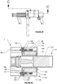
- FIG. 11 is a Section view of FIG. 10 ;
- FIG. 13B is a magnified Detail of FIG. 13A ;
- FIG. 14 is another Top view of the Multi-Barrel Split-breech Rapid Fire Gun
- FIG. 17 is a Top view of the firing assembly
- FIG. 18 is a Section view of FIG. 17 ;
- FIG. 20 is an Isometric view of the handguard-grip assembly
- FIG. 24 is an Isometric view of the wet-magazine assembly
- FIG. 25 is an Isometric view of the mainframe assembly
- FIG. 27 is an Isometric view of the rear housing and trigger assembly
- FIG. 28 is an Isometric view of the battery assembly
- FIG. 30 is a Section view of FIG. 29 .
- the embodiment described depicts a mechanism that incorporates a small caliber rim fire cartridge.
- This invention is scalable to any size, rim fire or center fire, cartridge.
- the multi-barrel split-breech rapid fire gun consists of ten sub-assemblies. These assemblies are the firing assembly 1 , the handguard-grip assembly 2 , the front housing assembly 3 , the chain drive assembly 4 , the receiver assembly 5 , the wet-magazine assembly 6 , the mainframe assembly 7 , the motor drive assembly 8 , the rear housing and trigger guard assembly 9 , and the battery assembly 10 .
- the mainframe assembly 7 is the assembly that forms the structural center of the gun. This assembly houses and supports the firing mechanisms.
- the firing assembly 1 consist of a plurality of barrels 11 attached to a barrel hub 13 by means of barrel interface threads 29 .
- a barrel support 12 supports the barrels at the distal end and is secured to the barrels by barrel support set screws 25 .
- the barrel hub 13 is secured by rear shaft 22 constrained by rear barrel hub bearing 87 in the mainframe housing 80 , as part of the mainframe assembly 7 .
- the barrel hub 13 is secured in the front by the front shaft 30 constrained by the front barrel hub bearing 52 in front housing 50 .
- the front housing 50 as part of the front housing assembly 3 , is connected to the mainframe assembly 7 by a plurality of front housing screws 81 screwed into the front housing screw bosses 53 .
- Front housing 50 contains a plurality of cooling apertures 54 to ventilate and cool the firing mechanism.
- the barrel hub 13 includes a plurality of hub half-chamber 14 features concentric with the rifle bore 35 in barrel 11 .
- This half-chamber 14 is half of the split breech.
- the other half of the split breech is the chain half-chamber 63 feature on the half-chamber chain link 66 as part of the chain drive assembly 4 .
- the plurality of half-chamber chain links 66 is connected to form the half-chamber chain 60 by a plurality of chain link pins 61 installed in the pin aperture 62 on each half-chamber chain link 66 .
- the half-chamber chain 60 path wraps around the barrel hub 13 , around ejection drive sprocket 67 , around two idler sprockets 73 and around input drive sprocket 77 .
- the idler sprockets 73 rotate on the chain idler shafts 71 attached to the mainframe housing 80 and idler shaft bushings 72 .
- the ejection drive sprocket 67 and the input drive sprocket 77 are driven by chain drive shafts 82 passing through drive sprocket aperture 69 and lock onto the shaft by drive sprocket set screw 68 .
- the chain drive shafts 82 are captured on the distal ends by hub front shaft bearing 51 located in front housing 50 and rear chain shaft bearing 83 on the mainframe housing 80 as part of the mainframe assembly 7 .
- a mid-shaft bearing 86 in mainframe housing 80 also supports the chain drive shafts 82 .
- Each chain drive shaft 82 is driven by a chain shaft gear 84 secured to the shaft by shaft gear set screw 85 .
- the chain shaft gears 84 mesh with drive chain gear 108 on the motor drive assembly 8 .
- This meshing arrangement synchronizes the chain half-chamber 63 on the half-chamber chain link 66 with the hub half-chamber 14 on the barrel hub 13 by means of the half-chamber chain link 66 nesting in the sprocket cradle 70 in the chain sprockets.
- the barrel hub is driven by motor 100 as part of motor drive assembly 8 .
- the motor drives a 2:1 ratio gear reduction comprised of a drive gear 104 secured to the motor shaft by means of drive gear set screws 111 , driving the driven gear 107 attached to the drive chain gear 108 by means of a plurality of driven gear screws 109 .
- the motor 100 is connected to the drive gear housing 101 .
- the drive gear housing 101 is attached to the driven gear housing 106 by means of a plurality of drive gear housing screws 102 . This attachment captures the drive gear 104 and a distal and proximal drive gear bushing 103 .
- the motor drive assembly 8 is secured to the mainframe housing 80 by means of a plurality of driven gear housing screws 105 .
- the drive chain gear 108 is attached to the barrel hub 13 by chamber chain gear set screw 110 .
- the wet-magazine assembly 6 connects to the receiver assembly 5 by means of magazine retainer pawl 164 on magazine release 162 snapping into the magazine retainer aperture 177 on the magazine lid 170 .
- the magazine release 162 and magazine retainer pawl 164 is biased toward the magazine retainer aperture 177 by means of the magazine release spring 165 located in the receiver body 160 .
- the wet-magazine assembly 6 is released from the gun by pressing the magazine release actuator 163 to slide the magazine retainer pawl 164 , on the magazine release 162 , out of the magazine retainer aperture 177 .
- the receiver assembly 5 is affixed to the mainframe assembly 7 by a plurality of receiver screws 166 .
- the wet-magazine assembly 6 is comprised of the magazine lid 170 and the magazine housing 171 .
- the cartridge belt 172 is constructed with a high-temperature polyimide belt 174 that retains the cartridges 173 at a specific spacing to match the hub half-chamber 14 features in the barrel hub 13 .
- the cartridge belt 172 is fan-folded in the magazine housing 171 .
- a loader boss 175 , an integral part of the magazine lid 170 , and dampener spring 176 also part of the magazine lid 170 , positions the first cartridge on cartridge belt 172 directly above and touching the top surface of loader boss 175 . This positions the first cartridge 173 to be captured by the half-chamber chain 60 as the barrel hub 13 rotates.
- the dampener spring 176 also suppresses the inertia of the cartridge belt 172 in high-speed operation.
- a portion of the unused space in the wet-magazine 6 is filled with a solution 167 of water, propylene glycol and 1 % silicone lubricant. This solution 167 is transferred by the cartridge belt 172 cools, lubricates, and prevents corrosion of the firing mechanism and proximal ends of the barrels 11 .
- the firing pin mechanism an integral part of the firing assembly 1 , is comprised of a plurality of firing pins 17 , the firing pin cam 19 and thrust bearing 27 .
- the firing pins 17 are captured and slide freely in the firing pin slots 26 in the barrel hub 13 .
- a firing pin spring 18 one for each firing pin 17 , are captured on the proximal end by spring cavity 33 in firing pin 17 .
- the springs are captured on the distal end by the spring retainer plate 23 .
- the spring retainer plate 23 is secured to the barrel hub 13 by a plurality of spring retainer screws 28 .
- the firing pin cam 19 is held in a static non-rotating position by the safety actuator 90 and the eccentric safety shaft 89 .
- the eccentric safety shaft 89 is secured to the safety actuator 90 by eccentric shaft set screw 92 .
- the safety actuator 90 is retained in the safety actuator aperture 91 by spring clip 93 in the mainframe housing 80 as part of mainframe assembly 7 .
- Safety actuator 90 is limited in rotation and stopped at fire and safety positions by safety stop pin 88 in mainframe housing 80 .
- the safety actuator 90 is placed, by the user, in either the fire position or the safety position. In the fire position, the eccentric safety shaft 89 is located and constrained by the cam retainer well 31 on firing pin cam 19 fixing the cam relative to the mainframe.
- a cam follower 32 on firing pin 17 contacts and follows the cam ramp 20 on firing pin cam 19 .
- pressure is increased by loading the firing pin springs 18 .
- This pressure is translated through the thrust bearing 27 to cam stop 36 on barrel hub 13 .
- bias is increased on each firing pin spring 18 in turn.
- the lead firing pin cam follower 32 reaches the sear face 21 on cam ramp 20 . This is the firing position 37 defined by the point in the barrel hub 13 revolution where the half-chamber chain link 66 and hub half-chamber 14 are concentric and fully encase a cartridge.
- This firing position 37 is synchronized by the chain shaft gears 84 meshing with drive chain gear 108 as describe earlier.
- This position of the sear face 21 on cam ramp 20 allows the firing pin 17 and striker 24 , by means of the cam loaded bias of the firing pin spring 18 , to travel rapidly through the striker aperture 34 in barrel hub 13 .
- the striker 24 then hits the cartridge primer with enough inertia to set off the primer and fire the bullet. All the firing pins follow this action in turn. In this embodiment, six bullets are fired per revolution of the barrel hub.
- the half-chamber chain link 66 separates from the barrel hub 13 and is taken up by the ejection drive sprocket 67 on the exit side.
- Ejector slot 15 in the barrel hub 13 and ejection pawl 161 part of the receiver assembly 5 , strips the empty cartridges and cartridge belt 172 off the barrel hub 13 to be routed through the exit aperture 55 in the front housing 50 and out of the gun.
- the eccentric safety shaft 89 pushes against the retainer well 31 on firing pin cam 19 to slide the firing pin cam 19 back away from the normal firing position where the striker 24 cannot contact the cartridge.
- a pressure fence 74 is attached to the mainframe housing 80 , and held concentric to the barrel hub 13 by means of a plurality of retaining screws 76 . Contact of the link pressure face 64 on half-chamber chain link 66 and the stop surface 75 on the pressure fence 74 constrains this movement.
- the motor housing and trigger guard assembly 9 connects to the mainframe assembly 7 by a plurality of motor housing screws 127 .
- the motor housing 120 protects the motor drive assembly 8 and provides a mounting point for the rear handle 134 .
- the rear handle 134 is composed of the left trigger grip 128 and the right trigger grip 129 .
- the rear handle 134 is attached to the motor housing 120 by trigger grip retainer 130 and trigger grip retainer screw 131 .
- the left trigger grip 128 and the right trigger grip 129 capture the trigger lever 133 and power switch 132 .
- the trigger mechanism is shown as the trigger lever 133 pressing against the power switch 132 to power the motor drive assembly 8 and fire the gun at the maximum motor speed.
- the power switch 132 can be replaced with an electronic speed control module, such as used in a power drill, that will allow the gun to have a variable firing rate.
- the battery assembly 10 consist of a plastic non-conductive battery housing 140 , a battery housing cover 141 and a plurality of rechargeable batteries 144 .
- the battery housing cover 141 is attached to the battery housing 140 by means of a plurality of cover screws 142 .
- a battery power switch 143 snaps into the battery housing cover 141 .
- This switch 143 switches battery assembly 10 ON or OFF.
- Power to the gun is connected by means of a positive magnetic contact 148 and a negative magnetic contact 150 .
- These contacts are secured to the battery housing 140 by a magnet screw 149 screwing into a contact stand-off 145 , one for each contact, located in the battery housing 140 .
- the batteries are connected to the contact stand-offs 145 by means of an electrical ring terminal 146 and a terminal screw 147 .
- the battery assembly 10 is slid onto the rear housing assembly 9 through the battery assembly aperture 151 and magnetically locked to the rear housing assembly 9 by a corresponding positive magnet 122 and negative magnet 135 on the motor housing 120 .
- Positive magnet 122 and negative magnet 135 are electrically isolated from the metal motor housing 120 by means of a plastic shoulder washer 123 and a plastic washer 124 .
- the magnets are connected to the motor 100 by motor terminal screw 121 , motor ring terminal 125 and nut 126 .
- the handguard-grip assembly 2 consists of a handguard 41 and a front grip 44 .
- the handguard-grip assembly 2 attaches to the front housing assembly 3 by means of a plurality of handguard screws 43 .
- the front grip 44 is attached to the handguard 41 by a grip retainer 45 and a grip retainer screw 46 screwing into the screw aperture 48 on front grip 44 .
- Handguard 41 includes a plurality of cooling apertures 42 to cool barrel 11 on firing assembly 1 . Grip alignment pins 47 on front grip 44 nest into the cooling apertures 42 as an anti-rotation device.
Abstract
The multi-barrel split-breech rapid fire gun is a light-weight, electrically-driven rapid fire gun, radially loaded and fired, using only rotating parts. This eliminates inertia problems compared to a breech-loaded gun that requires a bolt to chamber a cartridge. The firing mechanism allows the cartridge to be enclosed in a split-breech for 50% one rotation of the barrel hub. The gun incorporates an independent firing pin for each barrel to allow for high firing rates. The gun is fed by a thin polyimide cartridge belt fan-folded in a detachable wet-magazine.
Description
The present invention relates generally to the field of machine guns, and more particularly, to rapid fire rotating multi-barrel machine guns and the cartridge loading and ejection mechanisms in these guns.
Rapid fire multi-barrel guns have been used in military conflicts since the invention of the Gatling gun in the mid-19th century. These guns have the advantage of covering large areas of land and/or air with a high density of projectiles in a very short time period. Applications of this type of weapon are from flushing combatants out of thick jungles to launching a wall of projectiles to protect from high-speed missile attacks. Most modern rapid fire guns are heavy and require a large power source to operate. Some have been miniaturized for transport by one solider but are still very heavy and awkward to handle.
The current designs suffer from the need to use a delinker, inertia problems with the bolt action, and cam dwell problems in the firing position. This limits consistent fire rates to approximately 4000 rounds per minute, an inherent problem with axial breech-loaded rapid fire weapons.
The invention described herein is a radial loaded split-breech rapid fire gun. Split-breech designs have been tried previously for rapid firing guns such as the Fokker-Leimberger design at the close of WWII. This design and others like it use a nutcracker-type mechanism where the cartridge is chambered with a split-breech system by two rotating synchronized wheels with a plurality of chamber slots. The obvious problem with the mechanism is that the chamber is, in effect, closed for a very small-time window. This limits the speed that the wheels can turn due to deflagration and firing pin timing. In the case of the Fokker-Leimberger design, cartridge casings were split due to the low chambering time and cartridge ignition timing.
Thus, disclosed is a multi-barrel split-breech rapid fire gun that incorporates a multi-barrel assembly having a barrel hub with a plurality of barrels attached. Each barrel location around the barrel hub includes a half-chamber feature, concentric with the barrel bore at the proximal end of each barrel. This is one side of the split-breech system. The other side is a continuous chain with half-chambers as a feature of each link. The chain runs concentric to the barrel hub and the half-chamber features of each link are coincident with the barrel hub chamber feature. The chain drive system is synchronized to the barrel hub by chain sprockets, gear-driven by a drive gear affixed to the barrel hub.
The barrel hub is rotated by an electrical motor and gear reduction. The barrel hub also includes a plurality of firing pins, one for each barrel, and a cam-driven system to spring load and release each firing pin at the correct firing time. A high-temperature polyimide belt connecting a plurality of cartridges is fan-folded in a wet-magazine. A portion of the unused space in the magazine is filled with water, propylene glycol and 1% silicone lubricant. This mixture is transferred by the cartridge belt to cool and lubricate the high-speed mechanism. This magazine snap fits into a receiver located at the bottom of the gun. A boss feature and a spring, as part of the magazine, positions the first cartridge on the belt to be captured when the magazine is inserted.
As the barrel hub rotates, this polymeric belt (e.g., polyimide belt) with a plurality of cartridges affixed at a proper spacing, are captured and the cartridges nested into the half-chamber features on the barrel hub. As the barrel hub continues to rotate, the cartridges are enclosed by the half-chamber feature on the chain links. At the point in the barrel hub revolution where both half-chambers are concentric and fully encase a cartridge, the relative firing pin is released and the bullet is fired through the barrel. The cartridge remains fully chambered for 180 degrees of the barrel hub rotation. The cam that controls firing pin release time can be independently adjusted to control ignition timing within this 180-degree arc. With long chamber times, speed can be increased as the firing mechanism timing becomes less critical.
The internal pressure of the cartridge is contained within the half-chamber chain link and half-chamber feature in the barrel hub. A pressure fence, as part of the main frame enclosure, concentric to the barrel hub and within the firing positions, and in close proximity to the chain link top surface, limits any blow-out travel of the link as a result of internal chamber pressure. The interface between the half-chambered link and the half-chambered hub is sealed by means of the high-temperature polyimide belt that also connects each cartridge to the adjacent cartridge.
As the empty cartridges are rotated around the barrel hub, the chain link half-chamber separates from the barrel hub and is taken up by the chain sprocket on the exit side. A slot in the barrel hub and a pawl, part of the receiver assembly, strips the empty cartridges and belt off the barrel hub to be routed through an aperture in the front housing and out of the gun.
A rechargeable battery is magnetically and electrically attached to the gun to provide power to the drive motor.
In certain aspects, disclosed is a multi-barrel split-breech rapid fire gun comprising (a) a housing with a handle and trigger positioned thereon, the trigger operatively connected to a motor drive assembly; (b) a motor drive assembly arranged within the housing having a rotation member that rotates when the trigger is actuated; (c) a chain drive assembly that is operatively connected to the rotation member of the motor drive assembly, the chain drive assembly comprising an endless belt having a plurality of connected, individual links, with each individual link having a half breech or chamber formed thereon and in which the endless belt is configured to rotate within the gun when the trigger is actuated; (d) a firing assembly that is adjacent to and operatively connected to the chain drive assembly and motor drive assembly, the firing assembly comprising: (i) a plurality of rotatable barrels arranged on the multi-barrel split-breech rapid fire gun that are spaced apart from the trigger; (ii) a rotatable barrel hub with a plurality of cartridge half breeches or chambers formed thereon, the rotatable barrel hub synchronously rotates with the individual links of the endless belt such that each cartridge half breech or chamber formed on the rotatable barrel hub is configured to align with a corresponding half breech or chamber formed on each individual link of the endless belt to form a complete cartridge breech or chamber that is configured to temporarily house a cartridge therein before firing the cartridge through one barrel of the plurality of rotatable barrels; and (iii) a cartridge inlet configured to align with a cartridge magazine and a spent cartridge outlet arranged opposite to the cartridge inlet; and (e) optionally a cartridge magazine configured to releasably and securely mate to the housing and align with the cartridge inlet such that cartridges are fed from the magazine through the cartridge inlet into the complete cartridge breech or chamber formed by the aligned half breeches or chambers and rotate through the firing assembly such that spent cartridges exit the cartridge outlet such that the spent cartridges remain linked to one another after exiting the cartridge outlet.
In certain aspects, the cartridge magazine is present in the multi-barrel split-breech rapid fire gun.
In certain aspects in the multi-barrel split-breech rapid fire gun, the cartridge magazine houses a plurality of connected cartridges with each cartridge connected to another cartridge by a flexible polymeric belt and includes a lubricating solution that partially coats the plurality of connected cartridges therein.
In certain aspects in the multi-barrel split-breech rapid fire gun, the lubricating solution is configured to cool and lubricate the firing assembly when firing cartridges from the gun and comprises a mixture of water, an unsaturated polyol, and silicone.
In certain aspects in the multi-barrel split-breech rapid fire gun, the firing assembly further comprises a plurality of biased rotatable firing pins, with at least one firing pin of the plurality of biased rotatable firing pins configured to axially align with the complete cartridge breech or chamber formed within the gun while in use and to move in a linear direction from the handle towards one barrel of the plurality of rotatable barrels to fire the cartridge through one barrel of the plurality of rotatable barrels.
In certain aspects in the multi-barrel split-breech rapid fire gun, the rotation member of motor drive assembly comprises a plurality of sprockets that are operatively connected to a drive motor, the plurality of sprockets are arranged to contact an inner surface of the endless belt and rotate the endless belt within the multi-barrel split breech rapid fire gun.
In certain aspects in the multi-barrel split-breech rapid fire gun, the half breech or chamber of each link is formed on an outer surface of the endless belt opposite the inner surface of the endless belt.
In certain aspects, the multi-barrel split breech rapid fire gun further comprises a firing pin cam that houses the plurality of firing pins therein, an inner surface of the firing pin cam arranged as partially concentric rings having raised and recess portions in which when each rotatable firing pin rotates immediately from the raised to recess portion of the firing pin cam the firing pin moves radially outward aligning with a biasing cavity that biases the firing pin in a linear direction from the handle towards one barrel of the plurality of rotatable barrels to fire the cartridge through one barrel of the plurality of rotatable barrels.
In certain aspects, the multi-barrel split breech rapid fire gun is an automatic or semi-automatic firearm.
In certain aspects, the multi-barrel split breech rapid fire gun is a semi-automatic firearm.
In certain aspects, also disclosed is a plurality of assemblies configured for a multi-barrel split-breech rapid fire gun, the plurality of assemblies comprising: (a) a chain drive assembly that configure to be operatively connected to a rotation member of a motor drive assembly in a multi-barrel split-breech rapid fire gun, the chain drive assembly comprising an endless belt having a plurality of connected, individual links, with each individual link having a half breech or chamber formed thereon and in which the endless belt is configured to rotate within the gun when a trigger is actuated; (b) a firing assembly configured to be adjacent to and operatively connected to the chain drive assembly, the firing assembly comprising: (i) a plurality of rotatable barrels to be arranged on the multi-barrel split-breech rapid fire gun; (ii) a rotatable barrel hub with a plurality of cartridge half breeches or chambers formed thereon, the rotatable barrel hub configured to synchronously rotate with the individual links of the endless belt such that each cartridge half breech or chamber formed on the rotatable barrel hub is configured to align with a corresponding half breech or chamber formed on each individual link of the endless belt to form a complete cartridge breech or chamber that is configured to temporarily house a cartridge therein before firing a cartridge through one barrel of the plurality of rotatable barrels; and (iii) a cartridge inlet configured to align with a cartridge magazine and a spent cartridge outlet arranged opposite to the cartridge inlet.
In certain aspects, the plurality of assemblies further comprises: (c) a cartridge magazine configured to releasably and securely align with the cartridge inlet such that cartridges are configured to be fed from the magazine through the cartridge inlet into the complete cartridge breech or chamber formed by the aligned half breeches or chambers and rotate through the firing assembly such that spent cartridges exit the cartridge outlet such that the spent cartridges remain linked to one another after exiting the cartridge outlet.
In certain aspects in the plurality of assemblies, the cartridge magazine houses a plurality of connected cartridges with each cartridge connected to another cartridge by a flexible polymeric belt and includes a lubricating solution that partially coats the plurality of connected cartridges therein.
In certain aspects in the plurality of assemblies, the lubricating solution is configured to cool and lubricate the firing assembly when firing cartridges from the gun and comprises a mixture of water, an unsaturated polyol, and silicone.
In certain aspects in the plurality of assemblies, the firing assembly further comprises a plurality of biased rotatable firing pins, with at least one firing pin of the plurality of biased rotatable firing pins configured to axially align with the complete cartridge breech or chamber formed within the gun while in use and to move in a linear direction from the handle towards one barrel of the plurality of rotatable barrels to fire the cartridge through one barrel of the plurality of rotatable barrels.
In certain aspects in the plurality of assemblies, the half breech or chamber of each link is formed on an outer surface of the endless belt opposite the inner surface of the endless belt, with the inner surface of the endless belt configured to directly contact a rotation member of a motor drive assembly.
In certain aspects, the plurality of assemblies further comprises a firing pin cam that houses the plurality of firing pins therein, an inner surface of the firing pin cam arranged as partially concentric rings having raised and recess portions in which when each rotatable firing pin rotates immediately from the raised to recess portion of the firing pin cam, the firing pin moves radially outward aligning with a biasing cavity that biases the firing pin in a linear direction from the handle towards one barrel of the plurality of rotatable barrels to fire the cartridge through one barrel of the plurality of rotatable barrels.
Embodiments of the invention can include one or more or any combination of the above features and configurations.
Additional features, aspects and advantages of the invention will be set forth in the detailed description which follows, and in part will be readily apparent to those skilled in the art from that description or recognized by practicing the invention as described herein. It is to be understood that both the foregoing general description and the following detailed description present various embodiments of the invention, and are intended to provide an overview or framework for understanding the nature and character of the invention as it is claimed. The accompanying drawings are included to provide a further understanding of the invention, and are incorporated in and constitute a part of this specification.
These and other features, aspects and advantages of the present invention are better understood when the following detailed description of the invention is read with reference to the accompanying drawings, in which:
The present invention will now be described more fully hereinafter with reference to the accompanying drawings in which exemplary embodiments of the invention are shown. However, the invention may be embodied in many different forms and should not be construed as limited to the representative embodiments set forth herein. The exemplary embodiments are provided so that this disclosure will be thorough and complete, and will fully convey the scope of the invention and enable one of ordinary skill in the art to make, use and practice the invention. Like reference numbers refer to like elements throughout the various drawings.
The embodiment described depicts a mechanism that incorporates a small caliber rim fire cartridge. This invention is scalable to any size, rim fire or center fire, cartridge.
Referring to FIGS. 1, 2, 3, 4, 5, 6, 7 13B, 15, 16 and 30, the multi-barrel split-breech rapid fire gun consists of ten sub-assemblies. These assemblies are the firing assembly 1, the handguard-grip assembly 2, the front housing assembly 3, the chain drive assembly 4, the receiver assembly 5, the wet-magazine assembly 6, the mainframe assembly 7, the motor drive assembly 8, the rear housing and trigger guard assembly 9, and the battery assembly 10. The mainframe assembly 7 is the assembly that forms the structural center of the gun. This assembly houses and supports the firing mechanisms.
Referring to FIGS. 8, 9A, 9B, 11, 13A, 13B, 15, 18 19A, 19B, 20, 21, 22, 23, 24, 25, 26, 27 and 30, the firing assembly 1 consist of a plurality of barrels 11 attached to a barrel hub 13 by means of barrel interface threads 29. A barrel support 12 supports the barrels at the distal end and is secured to the barrels by barrel support set screws 25. The barrel hub 13 is secured by rear shaft 22 constrained by rear barrel hub bearing 87 in the mainframe housing 80, as part of the mainframe assembly 7. The barrel hub 13 is secured in the front by the front shaft 30 constrained by the front barrel hub bearing 52 in front housing 50. The front housing 50, as part of the front housing assembly 3, is connected to the mainframe assembly 7 by a plurality of front housing screws 81 screwed into the front housing screw bosses 53. Front housing 50 contains a plurality of cooling apertures 54 to ventilate and cool the firing mechanism.
Referring to FIGS. 8, 9A, 9B, 10, 11, 12, 13A, 13B, 18, 22 and 30 , the barrel hub 13 includes a plurality of hub half-chamber 14 features concentric with the rifle bore 35 in barrel 11. This half-chamber 14 is half of the split breech. The other half of the split breech is the chain half-chamber 63 feature on the half-chamber chain link 66 as part of the chain drive assembly 4. The plurality of half-chamber chain links 66 is connected to form the half-chamber chain 60 by a plurality of chain link pins 61 installed in the pin aperture 62 on each half-chamber chain link 66. The half-chamber chain 60 path wraps around the barrel hub 13, around ejection drive sprocket 67, around two idler sprockets 73 and around input drive sprocket 77. The idler sprockets 73 rotate on the chain idler shafts 71 attached to the mainframe housing 80 and idler shaft bushings 72.
Referring to FIGS. 13, 21, 22 and 25 , the ejection drive sprocket 67 and the input drive sprocket 77 are driven by chain drive shafts 82 passing through drive sprocket aperture 69 and lock onto the shaft by drive sprocket set screw 68. The chain drive shafts 82 are captured on the distal ends by hub front shaft bearing 51 located in front housing 50 and rear chain shaft bearing 83 on the mainframe housing 80 as part of the mainframe assembly 7. A mid-shaft bearing 86 in mainframe housing 80 also supports the chain drive shafts 82. Each chain drive shaft 82 is driven by a chain shaft gear 84 secured to the shaft by shaft gear set screw 85.
Referring to FIGS. 8, 9A, 9B, 10, 11, 12, 13A, 13B, 22, 25 and 26 , the chain shaft gears 84 mesh with drive chain gear 108 on the motor drive assembly 8. This meshing arrangement synchronizes the chain half-chamber 63 on the half-chamber chain link 66 with the hub half-chamber 14 on the barrel hub 13 by means of the half-chamber chain link 66 nesting in the sprocket cradle 70 in the chain sprockets.
The barrel hub is driven by motor 100 as part of motor drive assembly 8. In this embodiment, the motor drives a 2:1 ratio gear reduction comprised of a drive gear 104 secured to the motor shaft by means of drive gear set screws 111, driving the driven gear 107 attached to the drive chain gear 108 by means of a plurality of driven gear screws 109. The motor 100 is connected to the drive gear housing 101. The drive gear housing 101 is attached to the driven gear housing 106 by means of a plurality of drive gear housing screws 102. This attachment captures the drive gear 104 and a distal and proximal drive gear bushing 103. The motor drive assembly 8 is secured to the mainframe housing 80 by means of a plurality of driven gear housing screws 105. The drive chain gear 108 is attached to the barrel hub 13 by chamber chain gear set screw 110.
Referring to FIGS. 4, 5, 6, 9A, 9B, 10, 11, 14, 15, 16, 18, 23 and 24 , the wet-magazine assembly 6 connects to the receiver assembly 5 by means of magazine retainer pawl 164 on magazine release 162 snapping into the magazine retainer aperture 177 on the magazine lid 170. The magazine release 162 and magazine retainer pawl 164 is biased toward the magazine retainer aperture 177 by means of the magazine release spring 165 located in the receiver body 160. The wet-magazine assembly 6 is released from the gun by pressing the magazine release actuator 163 to slide the magazine retainer pawl 164, on the magazine release 162, out of the magazine retainer aperture 177. The receiver assembly 5 is affixed to the mainframe assembly 7 by a plurality of receiver screws 166.
The wet-magazine assembly 6 is comprised of the magazine lid 170 and the magazine housing 171. The cartridge belt 172 is constructed with a high-temperature polyimide belt 174 that retains the cartridges 173 at a specific spacing to match the hub half-chamber 14 features in the barrel hub 13. The cartridge belt 172 is fan-folded in the magazine housing 171. A loader boss 175, an integral part of the magazine lid 170, and dampener spring 176 also part of the magazine lid 170, positions the first cartridge on cartridge belt 172 directly above and touching the top surface of loader boss 175. This positions the first cartridge 173 to be captured by the half-chamber chain 60 as the barrel hub 13 rotates. The dampener spring 176 also suppresses the inertia of the cartridge belt 172 in high-speed operation. A portion of the unused space in the wet-magazine 6 is filled with a solution 167 of water, propylene glycol and 1% silicone lubricant. This solution 167 is transferred by the cartridge belt 172 cools, lubricates, and prevents corrosion of the firing mechanism and proximal ends of the barrels 11.
Referring to FIGS. 8, 9A, 9B, 10, 11, 12, 13A, 13B, 14, 15, 16, 17, 18, 19A, 19B, 21, 22, 23, 25 and 30 , the firing pin mechanism, an integral part of the firing assembly 1, is comprised of a plurality of firing pins 17, the firing pin cam 19 and thrust bearing 27. The firing pins 17 are captured and slide freely in the firing pin slots 26 in the barrel hub 13. A firing pin spring 18, one for each firing pin 17, are captured on the proximal end by spring cavity 33 in firing pin 17. The springs are captured on the distal end by the spring retainer plate 23. The spring retainer plate 23 is secured to the barrel hub 13 by a plurality of spring retainer screws 28.
The firing pin cam 19 is held in a static non-rotating position by the safety actuator 90 and the eccentric safety shaft 89. The eccentric safety shaft 89 is secured to the safety actuator 90 by eccentric shaft set screw 92. The safety actuator 90 is retained in the safety actuator aperture 91 by spring clip 93 in the mainframe housing 80 as part of mainframe assembly 7. Safety actuator 90 is limited in rotation and stopped at fire and safety positions by safety stop pin 88 in mainframe housing 80. The safety actuator 90 is placed, by the user, in either the fire position or the safety position. In the fire position, the eccentric safety shaft 89 is located and constrained by the cam retainer well 31 on firing pin cam 19 fixing the cam relative to the mainframe. As the barrel hub 13 is rotated along with the firing pins 17, a cam follower 32 on firing pin 17 contacts and follows the cam ramp 20 on firing pin cam 19. As the barrel hub 13 rotates inside of the firing pin cam 19, pressure is increased by loading the firing pin springs 18. This pressure is translated through the thrust bearing 27 to cam stop 36 on barrel hub 13. As each firing pin 17 climbs the cam ramp 20, bias is increased on each firing pin spring 18 in turn. As the barrel hub 13 continues to rotate, the lead firing pin cam follower 32 reaches the sear face 21 on cam ramp 20. This is the firing position 37 defined by the point in the barrel hub 13 revolution where the half-chamber chain link 66 and hub half-chamber 14 are concentric and fully encase a cartridge. This firing position 37 is synchronized by the chain shaft gears 84 meshing with drive chain gear 108 as describe earlier. This position of the sear face 21 on cam ramp 20 allows the firing pin 17 and striker 24, by means of the cam loaded bias of the firing pin spring 18, to travel rapidly through the striker aperture 34 in barrel hub 13. The striker 24 then hits the cartridge primer with enough inertia to set off the primer and fire the bullet. All the firing pins follow this action in turn. In this embodiment, six bullets are fired per revolution of the barrel hub.
As the empty cartridges 169 are rotated around the barrel hub 13, the half-chamber chain link 66 separates from the barrel hub 13 and is taken up by the ejection drive sprocket 67 on the exit side. Ejector slot 15 in the barrel hub 13 and ejection pawl 161, part of the receiver assembly 5, strips the empty cartridges and cartridge belt 172 off the barrel hub 13 to be routed through the exit aperture 55 in the front housing 50 and out of the gun.
In the safety position of the safety actuator 90, the eccentric safety shaft 89 pushes against the retainer well 31 on firing pin cam 19 to slide the firing pin cam 19 back away from the normal firing position where the striker 24 cannot contact the cartridge.
When the bullet is fired, maximum pressure caused by the propellant is exerted on the split-breech half-chamber chain link 66 and hub half-chamber 14 on barrel hub 13. The half-chamber chain link 66 will tend to blow outward, away from the barrel hub 13. A pressure fence 74 is attached to the mainframe housing 80, and held concentric to the barrel hub 13 by means of a plurality of retaining screws 76. Contact of the link pressure face 64 on half-chamber chain link 66 and the stop surface 75 on the pressure fence 74 constrains this movement.
In normal operation, as the barrel hub 13 rotates, the high-temperature polyimide belt 174 on the cartridge belt 172 becomes trapped between the half-chamber chain link 66 and the barrel hub 13. A belt relief 16 in barrel hub 13 allows for the thickness on the high-temperature polyimide belt 174.
Referring to FIGS. 5, 7, 8, 9A, 9B, 12, 13A, 16 and 27 , the motor housing and trigger guard assembly 9 connects to the mainframe assembly 7 by a plurality of motor housing screws 127. The motor housing 120 protects the motor drive assembly 8 and provides a mounting point for the rear handle 134. The rear handle 134 is composed of the left trigger grip 128 and the right trigger grip 129. The rear handle 134 is attached to the motor housing 120 by trigger grip retainer 130 and trigger grip retainer screw 131. The left trigger grip 128 and the right trigger grip 129 capture the trigger lever 133 and power switch 132. In this embodiment the trigger mechanism is shown as the trigger lever 133 pressing against the power switch 132 to power the motor drive assembly 8 and fire the gun at the maximum motor speed. In other embodiments (not shown) the power switch 132 can be replaced with an electronic speed control module, such as used in a power drill, that will allow the gun to have a variable firing rate.
Referring to FIGS. 5, 7, 8, 9A, 9B, 12, 13A, 13B, 16, 27, 28, 29 and 30 , the battery assembly 10 consist of a plastic non-conductive battery housing 140, a battery housing cover 141 and a plurality of rechargeable batteries 144. The battery housing cover 141 is attached to the battery housing 140 by means of a plurality of cover screws 142. A battery power switch 143 snaps into the battery housing cover 141. This switch 143 switches battery assembly 10 ON or OFF. Power to the gun is connected by means of a positive magnetic contact 148 and a negative magnetic contact 150. These contacts are secured to the battery housing 140 by a magnet screw 149 screwing into a contact stand-off 145, one for each contact, located in the battery housing 140. The batteries are connected to the contact stand-offs 145 by means of an electrical ring terminal 146 and a terminal screw 147. The battery assembly 10 is slid onto the rear housing assembly 9 through the battery assembly aperture 151 and magnetically locked to the rear housing assembly 9 by a corresponding positive magnet 122 and negative magnet 135 on the motor housing 120.
Referring to FIGS. 1, 2, 3, 4, 6, 7, 9A, 9B, 13A, 13B, 15, 16, 18, 20 and 21 , the handguard-grip assembly 2 consists of a handguard 41 and a front grip 44. The handguard-grip assembly 2 attaches to the front housing assembly 3 by means of a plurality of handguard screws 43. The front grip 44 is attached to the handguard 41 by a grip retainer 45 and a grip retainer screw 46 screwing into the screw aperture 48 on front grip 44. Handguard 41 includes a plurality of cooling apertures 42 to cool barrel 11 on firing assembly 1. Grip alignment pins 47 on front grip 44 nest into the cooling apertures 42 as an anti-rotation device.
- 1 firing assembly
- 2 handguard-grip assembly
- 3 front housing assembly
- 4 chain drive assembly
- 5 receiver assembly
- 6 wet-magazine assembly
- 7 mainframe assembly
- 8 motor drive assembly
- 9 rear housing and trigger guard assembly
- 10 battery assembly
- 11 barrel
- 12 barrel support
- 13 barrel hub
- 14 hub half-chamber
- 15 ejector slot
- 16 belt relief
- 17 firing pin
- 18 firing pin spring
- 19 firing pin cam
- 20 cam ramp
- 21 sear face
- 22 hub rear shaft
- 23 spring retainer plate
- 24 striker
- 25 barrel support set screw
- 26 firing pin slot
- 27 thrust bearing
- 28 spring retainer screw
- 29 barrel interface threads
- 30 hub front shaft
- 31 cam retainer well
- 32 cam follower
- 33 spring cavity
- 34 striker aperture
- 35 rifle bore
- 36 cam stop
- 37 firing position
- 38 not used
- 39 not used
- 40 not used
- 41 handguard
- 42 cooling aperture
- 43 handguard screws
- 44 front grip
- 45 grip retainer
- 46 grip retainer screw
- 47 grip alignment pin
- 48 screw aperture
- 49 not used
- 50 front housing
- 51 front shaft bearing
- 52 front barrel hub bearing
- 53 front housing screw boss
- 54 cooling aperture
- 55 exit aperture
- 56 not used
- 57 not used
- 58 not used
- 59 not used
- 60 half-chamber chain
- 61 chain link pin
- 62 pin aperture
- 63 chain half-chamber
- 64 link pressure face
- 65 not used
- 66 half-chamber chain link
- 67 ejection drive sprocket
- 68 drive sprocket set screw
- 69 drive sprocket aperture
- 70 sprocket cradle
- 71 chain idler shaft
- 72 idler shaft bushing
- 73 idler sprocket
- 74 pressure fence
- 75 stop surface
- 76 retaining screws
- 77 input drive sprocket
- 78 not used
- 79 not used
- 80 mainframe housing
- 81 front housing screw
- 82 chain drive shaft
- 83 rear chain shaft bearing
- 84 chain shaft gear
- 85 shaft gear set screw
- 86 mid-shaft bearing
- 87 rear barrel hub bearing
- 88 safety stop pin
- 89 eccentric safety shaft
- 90 safety actuator
- 91 safety actuator aperture
- 92 eccentric shaft set screw
- 93 spring clip
- 94 not used
- 95 not used
- 96 not used
- 97 not used
- 98 not used
- 99 not used
- 100 motor
- 101 drive gear housing
- 102 drive gear housing screw
- 103 drive gear bushings
- 104 drive gear
- 105 driven gear housing screw
- 106 driven gear housing
- 107 driven gear
- 108 drive chain gear
- 109 driven gear screw
- 110 chamber chain gear set screw
- 111 drive gear set screw
- 112 not used
- 113 not used
- 114 not used
- 115 not used
- 116 not used
- 117 not used
- 118 not used
- 119 not used
- 120 motor housing
- 121 motor terminal screw
- 122 positive magnet
- 123 shoulder washer
- 124 plastic washer
- 125 motor ring terminal
- 126 nut
- 127 motor housing screw
- 128 left trigger grip
- 129 right trigger grip
- 130 trigger grip retainer
- 131 trigger grip retainer screw
- 132 power switch
- 133 trigger lever
- 134 rear handle
- 135 negative magnet
- 136 not used
- 137 not used
- 138 not used
- 139 not used
- 140 battery housing
- 141 battery housing cover
- 142 cover screw
- 143 switch
- 144 battery
- 145 contact stand-off
- 146 ring terminal
- 147 terminal screw
- 148 positive magnetic contact
- 149 magnet screw
- 150 negative magnetic contact
- 151 battery assembly aperture
- 152 not used
- 153 not used
- 154 not used
- 155 not used
- 156 not used
- 157 not used
- 158 not used
- 159 not used
- 160 receiver body
- 161 ejection pawl
- 162 magazine release
- 163 magazine release actuator
- 164 magazine retainer pawl
- 165 magazine release spring
- 166 receiver screw
- 167 solution
- 168 not used
- 169 empty cartridge
- 170 magazine lid
- 171 magazine housing
- 172 cartridge belt
- 173 cartridge
- 174 high-temperature polyimide belt
- 175 loader boss
- 176 dampener spring
- 177 magazine retainer aperture
Claims (17)
1. A multi-barrel split-breech rapid fire gun comprising:
(a) a housing with a handle and trigger positioned thereon, the trigger operatively connected to a motor drive assembly;
(b) a motor drive assembly arranged within the housing having a rotation member that rotates when the trigger is actuated;
(c) a chain drive assembly that is operatively connected to the rotation member of the motor drive assembly, the chain drive assembly comprising an endless belt having a plurality of connected, individual links, with each individual link having a half breech or chamber formed thereon and in which the endless belt is configured to rotate within the gun when the trigger is actuated;
(d) a firing assembly that is adjacent to and operatively connected to the chain drive assembly and motor drive assembly, the firing assembly comprising:
(i) a plurality of rotatable barrels arranged on the multi-barrel split-breech rapid fire gun that are spaced apart from the trigger;
(ii) a rotatable barrel hub with a plurality of cartridge half breeches or chambers formed thereon, the rotatable barrel hub synchronously rotates with the individual links of the endless belt such that each cartridge half breech or chamber formed on the rotatable barrel hub is configured to align with a corresponding half breech or chamber formed on each individual link of the endless belt to form a complete cartridge breech or chamber that is configured to temporarily house a cartridge therein before firing the cartridge through one barrel of the plurality of rotatable barrels; and
(iii) a cartridge inlet configured to align with a cartridge magazine and a spent cartridge outlet arranged opposite to the cartridge inlet; and
(e) optionally a cartridge magazine configured to releasably and securely mate to the housing and align with the cartridge inlet such that cartridges are fed from the magazine through the cartridge inlet into the complete cartridge breech or chamber formed by the aligned half breeches or chambers and rotate through the firing assembly such that spent cartridges exit the cartridge outlet such that the spent cartridges remain linked to one another after exiting the cartridge outlet.
2. The multi-barrel split-breech rapid fire gun of claim 1 , wherein the cartridge magazine is present.
3. The multi-barrel split-breech rapid fire gun of claim 2 , wherein the cartridge magazine houses a plurality of connected cartridges with each cartridge connected to another cartridge by a flexible polymeric belt and includes a lubricating solution that partially coats the plurality of connected cartridges therein.
4. The multi-barrel split breech rapid fire gun of claim 3 , wherein the lubricating solution is configured to cool and lubricate the firing assembly when firing cartridges from the gun and comprises a mixture of water, an unsaturated polyol, and silicone.
5. The multi-barrel split breech rapid fire gun of claim 4 , wherein the firing assembly further comprises a plurality of biased rotatable firing pins, with at least one firing pin of the plurality of biased rotatable firing pins configured to axially align with the complete cartridge breech or chamber formed within the gun while in use and to move in a linear direction from the handle towards one barrel of the plurality of rotatable barrels to fire the cartridge through one barrel of the plurality of rotatable barrels.
6. The multi-barrel split breech rapid fire gun of claim 5 , wherein the rotation member of motor drive assembly comprises a plurality of sprockets that are operatively connected to a drive motor, the plurality of sprockets are arranged to contact an inner surface of the endless belt and rotate the endless belt within the multi-barrel split breech rapid fire gun.
7. The multi-barrel split breech rapid fire gun of claim 6 , wherein the half breech or chamber of each link is formed on an outer surface of the endless belt opposite the inner surface of the endless belt.
8. The multi-barrel split breech rapid fire gun of claim 7 , further comprising a firing pin cam that houses the plurality of firing pins therein, an inner surface of the firing pin cam arranged as partially concentric rings having raised and recess portions in which when each rotatable firing pin rotates immediately from the raised to recess portion of the firing pin cam the firing pin moves radially outward aligning with a biasing cavity that biases the firing pin in a linear direction from the handle towards one barrel of the plurality of rotatable barrels to fire the cartridge through one barrel of the plurality of rotatable barrels.
9. The multi-barrel split breech rapid fire gun of claim 8 , wherein the multi-barrel split breech rapid fire gun is an automatic or semi-automatic firearm.
10. The multi-barrel split breech rapid fire gun of claim 9 , wherein the multi-barrel split breech rapid fire gun is a semi-automatic firearm.
11. A plurality of assemblies configured for a multi-barrel split-breech rapid fire gun, the plurality of assemblies comprising:
(a) a chain drive assembly that configure to be operatively connected to a rotation member of a motor drive assembly in a multi-barrel split-breech rapid fire gun, the chain drive assembly comprising an endless belt having a plurality of connected, individual links, with each individual link having a half breech or chamber formed thereon and in which the endless belt is configured to rotate within the gun when a trigger is actuated; and
(b) a firing assembly configured to be adjacent to and operatively connected to the chain drive assembly, the firing assembly comprising:
(i) a plurality of rotatable barrels to be arranged on the multi-barrel split-breech rapid fire gun;
(ii) a rotatable barrel hub with a plurality of cartridge half breeches or chambers formed thereon, the rotatable barrel hub configured to synchronously rotate with the individual links of the endless belt such that each cartridge half breech or chamber formed on the rotatable barrel hub is configured to align with a corresponding half breech or chamber formed on each individual link of the endless belt to form a complete cartridge breech or chamber that is configured to temporarily house a cartridge therein before firing a cartridge through one barrel of the plurality of rotatable barrels; and
(iii) a cartridge inlet configured to align with a cartridge magazine and a spent cartridge outlet arranged opposite to the cartridge inlet.
12. The plurality of assemblies of claim 11 , further comprising: (c) a cartridge magazine configured to releasably and securely align with the cartridge inlet such that cartridges are configured to be fed from the magazine through the cartridge inlet into the complete cartridge breech or chamber formed by the aligned half breeches or chambers and rotate through the firing assembly such that spent cartridges exit the cartridge outlet such that the spent cartridges remain linked to one another after exiting the cartridge outlet.
13. The plurality of assemblies of claim 12 , wherein the cartridge magazine houses a plurality of connected cartridges with each cartridge connected to another cartridge by a flexible polymeric belt and includes a lubricating solution that partially coats the plurality of connected cartridges therein.
14. The plurality of assemblies of claim 13 , wherein the lubricating solution is configured to cool and lubricate the firing assembly when firing cartridges from the gun and comprises a mixture of water, an unsaturated polyol, and silicone.
15. The plurality of assemblies of claim 14 , wherein the firing assembly further comprises a plurality of biased rotatable firing pins, with at least one firing pin of the plurality of biased rotatable firing pins configured to axially align with the complete cartridge breech or chamber formed within the gun while in use and to move in a linear direction from the handle towards one barrel of the plurality of rotatable barrels to fire the cartridge through one barrel of the plurality of rotatable barrels.
16. The plurality of assemblies of claim 15 , wherein the half breech or chamber of each link is formed on an outer surface of the endless belt opposite the inner surface of the endless belt, with the inner surface of the endless belt configured to directly contact a rotation member of a motor drive assembly.
17. The plurality of assemblies of claim 15 , further comprising a firing pin cam that houses the plurality of firing pins therein, an inner surface of the firing pin cam arranged as partially concentric rings having raised and recess portions in which when each rotatable firing pin rotates immediately from the raised to recess portion of the firing pin cam the firing pin moves radially outward aligning with a biasing cavity that biases the firing pin in a linear direction from the handle towards one barrel of the plurality of rotatable barrels to fire the cartridge through one barrel of the plurality of rotatable barrels.
Priority Applications (1)
| Application Number | Priority Date | Filing Date | Title |
|---|---|---|---|
| US16/690,462 US10845141B2 (en) | 2018-11-21 | 2019-11-21 | Multi-barrel split-breach rapid fire gun |
Applications Claiming Priority (2)
| Application Number | Priority Date | Filing Date | Title |
|---|---|---|---|
| US201862770238P | 2018-11-21 | 2018-11-21 | |
| US16/690,462 US10845141B2 (en) | 2018-11-21 | 2019-11-21 | Multi-barrel split-breach rapid fire gun |
Publications (2)
| Publication Number | Publication Date |
|---|---|
| US20200158453A1 US20200158453A1 (en) | 2020-05-21 |
| US10845141B2 true US10845141B2 (en) | 2020-11-24 |
Family
ID=70727473
Family Applications (1)
| Application Number | Title | Priority Date | Filing Date |
|---|---|---|---|
| US16/690,462 Active US10845141B2 (en) | 2018-11-21 | 2019-11-21 | Multi-barrel split-breach rapid fire gun |
Country Status (1)
| Country | Link |
|---|---|
| US (1) | US10845141B2 (en) |
Families Citing this family (3)
| Publication number | Priority date | Publication date | Assignee | Title |
|---|---|---|---|---|
| US10871336B1 (en) * | 2018-10-30 | 2020-12-22 | Travis Johnston | Revolving battery machine gun with electronically controlled drive motors |
| US11754355B2 (en) * | 2021-09-06 | 2023-09-12 | Kristopher Lee Paulson | Minigun with integrated battery and motor control |
| US11796271B1 (en) * | 2022-08-30 | 2023-10-24 | Florian KOHLI | Firing pin release system |
Citations (29)
| Publication number | Priority date | Publication date | Assignee | Title |
|---|---|---|---|---|
| US323997A (en) * | 1885-08-11 | Machine-gun | ||
| US332741A (en) * | 1885-12-22 | Palmeb | ||
| US504831A (en) * | 1893-09-12 | Machine-gun | ||
| US3041939A (en) * | 1959-10-06 | 1962-07-03 | Dardick Corp | Multi-barrel gun with a plurality of firing stations and an ammunition drum |
| US3160021A (en) * | 1962-02-28 | 1964-12-08 | Ralph F Hereth | Rotary drive control mechanism |
| US3262367A (en) * | 1964-03-18 | 1966-07-26 | Honeywell Inc | Dual rotor machine gun |
| US3492913A (en) * | 1968-03-11 | 1970-02-03 | Trw Inc | Open chamber gun ammunition feed system |
| US3776416A (en) * | 1971-11-23 | 1973-12-04 | Gen Electric | Article handling system |
| US4210058A (en) * | 1978-09-25 | 1980-07-01 | General Electric Company | Balanced Gatling gun |
| US4301709A (en) * | 1979-06-08 | 1981-11-24 | Hughes Helicopters, Inc. | Mechanical anti-hangfire system |
| US4418607A (en) * | 1977-04-21 | 1983-12-06 | Hughes Helicopters, Inc. | Single barrel externally powdered gun |
| US4457209A (en) * | 1980-08-27 | 1984-07-03 | Fmc Corporation | Automated large caliber ammunition handling system |
| US4481858A (en) * | 1981-09-18 | 1984-11-13 | Hughes Helicopters, Inc. | Single barrel externally powered gun |
| US4681019A (en) * | 1984-12-21 | 1987-07-21 | Heckler & Koch Gmbh | Magazine for automatic weapons |
| US4735126A (en) * | 1982-03-27 | 1988-04-05 | Rheinmetall Gmbh | Cartridge feed for double-barrel gun |
| US5115713A (en) * | 1990-05-22 | 1992-05-26 | Oerlikon-Contraves Ag | Apparatus for the infeed of cartridges to a firing weapon |
| US6339983B1 (en) * | 1998-12-04 | 2002-01-22 | Oerlikon Contraves Ag | Ammunition-feeding device for a cannon |
| US20110083654A1 (en) * | 2009-07-02 | 2011-04-14 | Richard David Galinson | Paintball loader and paintball Galting gun |
| US20110120292A1 (en) * | 2007-12-13 | 2011-05-26 | Garwood Tracy W | Access door for feeder/delinker of a gatling gun |
| US20120118132A1 (en) * | 2009-07-22 | 2012-05-17 | Gary L Coker | High attrition, rapid dispersal x 8 (h.a.r.d. 8) extreme rate of fire weapon system |
| US20150300772A1 (en) * | 2013-10-18 | 2015-10-22 | Jerry Carson | Double-barrel pump shotguns |
| US20160195349A1 (en) * | 2013-06-03 | 2016-07-07 | Profense, Llc | Minigun with Improved Access Door |
| US20170205167A1 (en) * | 2016-01-19 | 2017-07-20 | Brian F. Abbott | Rotatable Firearm Rotor |
| US20180209762A1 (en) * | 2015-07-10 | 2018-07-26 | Rheinmetall Waffe Munition Gmbh | Weapon with a barrel cluster |
| US20180231343A1 (en) * | 2015-07-10 | 2018-08-16 | Rheinmetall Waffe Munition Gmbh | Recoil intensifier of an externally powered machine weapon, in particular a machine gun |
| US20180231344A1 (en) * | 2015-07-10 | 2018-08-16 | Rheinmetall Waffe Munition Gmbh | Modular weapon |
| US10352638B1 (en) * | 2018-04-23 | 2019-07-16 | Daycraft Weapon Systems, LLC | Gun having multi-drive link feed system and method therefor |
| US20200096270A1 (en) * | 2017-02-02 | 2020-03-26 | Michael Morency Cleary | Delinker mechanism for chain-driven machine gun |
| US20200141676A1 (en) * | 2018-09-11 | 2020-05-07 | Timothy Bryan Ralston | Multi-caliber survival weapon platform system for revolver/shotgun |
-
2019
- 2019-11-21 US US16/690,462 patent/US10845141B2/en active Active
Patent Citations (29)
| Publication number | Priority date | Publication date | Assignee | Title |
|---|---|---|---|---|
| US323997A (en) * | 1885-08-11 | Machine-gun | ||
| US332741A (en) * | 1885-12-22 | Palmeb | ||
| US504831A (en) * | 1893-09-12 | Machine-gun | ||
| US3041939A (en) * | 1959-10-06 | 1962-07-03 | Dardick Corp | Multi-barrel gun with a plurality of firing stations and an ammunition drum |
| US3160021A (en) * | 1962-02-28 | 1964-12-08 | Ralph F Hereth | Rotary drive control mechanism |
| US3262367A (en) * | 1964-03-18 | 1966-07-26 | Honeywell Inc | Dual rotor machine gun |
| US3492913A (en) * | 1968-03-11 | 1970-02-03 | Trw Inc | Open chamber gun ammunition feed system |
| US3776416A (en) * | 1971-11-23 | 1973-12-04 | Gen Electric | Article handling system |
| US4418607A (en) * | 1977-04-21 | 1983-12-06 | Hughes Helicopters, Inc. | Single barrel externally powdered gun |
| US4210058A (en) * | 1978-09-25 | 1980-07-01 | General Electric Company | Balanced Gatling gun |
| US4301709A (en) * | 1979-06-08 | 1981-11-24 | Hughes Helicopters, Inc. | Mechanical anti-hangfire system |
| US4457209A (en) * | 1980-08-27 | 1984-07-03 | Fmc Corporation | Automated large caliber ammunition handling system |
| US4481858A (en) * | 1981-09-18 | 1984-11-13 | Hughes Helicopters, Inc. | Single barrel externally powered gun |
| US4735126A (en) * | 1982-03-27 | 1988-04-05 | Rheinmetall Gmbh | Cartridge feed for double-barrel gun |
| US4681019A (en) * | 1984-12-21 | 1987-07-21 | Heckler & Koch Gmbh | Magazine for automatic weapons |
| US5115713A (en) * | 1990-05-22 | 1992-05-26 | Oerlikon-Contraves Ag | Apparatus for the infeed of cartridges to a firing weapon |
| US6339983B1 (en) * | 1998-12-04 | 2002-01-22 | Oerlikon Contraves Ag | Ammunition-feeding device for a cannon |
| US20110120292A1 (en) * | 2007-12-13 | 2011-05-26 | Garwood Tracy W | Access door for feeder/delinker of a gatling gun |
| US20110083654A1 (en) * | 2009-07-02 | 2011-04-14 | Richard David Galinson | Paintball loader and paintball Galting gun |
| US20120118132A1 (en) * | 2009-07-22 | 2012-05-17 | Gary L Coker | High attrition, rapid dispersal x 8 (h.a.r.d. 8) extreme rate of fire weapon system |
| US20160195349A1 (en) * | 2013-06-03 | 2016-07-07 | Profense, Llc | Minigun with Improved Access Door |
| US20150300772A1 (en) * | 2013-10-18 | 2015-10-22 | Jerry Carson | Double-barrel pump shotguns |
| US20180209762A1 (en) * | 2015-07-10 | 2018-07-26 | Rheinmetall Waffe Munition Gmbh | Weapon with a barrel cluster |
| US20180231343A1 (en) * | 2015-07-10 | 2018-08-16 | Rheinmetall Waffe Munition Gmbh | Recoil intensifier of an externally powered machine weapon, in particular a machine gun |
| US20180231344A1 (en) * | 2015-07-10 | 2018-08-16 | Rheinmetall Waffe Munition Gmbh | Modular weapon |
| US20170205167A1 (en) * | 2016-01-19 | 2017-07-20 | Brian F. Abbott | Rotatable Firearm Rotor |
| US20200096270A1 (en) * | 2017-02-02 | 2020-03-26 | Michael Morency Cleary | Delinker mechanism for chain-driven machine gun |
| US10352638B1 (en) * | 2018-04-23 | 2019-07-16 | Daycraft Weapon Systems, LLC | Gun having multi-drive link feed system and method therefor |
| US20200141676A1 (en) * | 2018-09-11 | 2020-05-07 | Timothy Bryan Ralston | Multi-caliber survival weapon platform system for revolver/shotgun |
Also Published As
| Publication number | Publication date |
|---|---|
| US20200158453A1 (en) | 2020-05-21 |
Similar Documents
| Publication | Publication Date | Title |
|---|---|---|
| US10845141B2 (en) | Multi-barrel split-breach rapid fire gun | |
| US4709617A (en) | Firearm | |
| US4856410A (en) | Firearm | |
| US8763508B2 (en) | High attrition, rapid dispersal X 8 (H.A.R.D. 8) extreme rate of fire weapon system | |
| US20210156632A1 (en) | Firearm system and method | |
| EP4033195A1 (en) | Selective fire firearm system and methods | |
| US6910404B2 (en) | Gun bolt locking mechanism | |
| US10941994B2 (en) | Cased telescoped ammunition firearm with dual feed | |
| US9958226B2 (en) | Systems and methods for providing a multi-shot firearm | |
| US10054390B1 (en) | Apparatus, kit and method for a blank-only machine non-firearm | |
| EP0195093B1 (en) | Ammunition magazine | |
| US2950652A (en) | Chambering mechanism for an automatic revolver type gun | |
| US2976770A (en) | Operating mechanism for a plural barrel rifle with a feeding rotor | |
| US4311081A (en) | Dual, two stage shell feeding apparatus for guns | |
| US4311082A (en) | General purpose automatic weapon system | |
| US3608424A (en) | Feeding mechanism of an automatic cannon for firing caseless ammunition | |
| GB2206188A (en) | Firearm | |
| US10955207B1 (en) | Flat loop revolving firearm assembly | |
| RU2709429C1 (en) | Automatic curved barrel revolver with cylindrical drum | |
| CN210813625U (en) | Fire control shell bullet chain and fire gun | |
| EP0038847A1 (en) | Two stage shell feeding apparatus with shell feeding path control | |
| US4102241A (en) | High-rate-of-fire rifle mechanism or dual cyclic rate mechanism | |
| US5513550A (en) | Firearm with pivoting barrel | |
| US11041686B2 (en) | Electronic firing rifle assembly | |
| RU2460958C1 (en) | Multi-charge small arm gas-escape reload mechanism |
Legal Events
| Date | Code | Title | Description |
|---|---|---|---|
| FEPP | Fee payment procedure |
Free format text: ENTITY STATUS SET TO UNDISCOUNTED (ORIGINAL EVENT CODE: BIG.); ENTITY STATUS OF PATENT OWNER: SMALL ENTITY |
|
| FEPP | Fee payment procedure |
Free format text: ENTITY STATUS SET TO SMALL (ORIGINAL EVENT CODE: SMAL); ENTITY STATUS OF PATENT OWNER: SMALL ENTITY |
|
| STPP | Information on status: patent application and granting procedure in general |
Free format text: NOTICE OF ALLOWANCE MAILED -- APPLICATION RECEIVED IN OFFICE OF PUBLICATIONS |
|
| STPP | Information on status: patent application and granting procedure in general |
Free format text: PUBLICATIONS -- ISSUE FEE PAYMENT VERIFIED |
|
| STCF | Information on status: patent grant |
Free format text: PATENTED CASE |