US10844690B2 - Dual lock flow gate - Google Patents
Dual lock flow gate Download PDFInfo
- Publication number
- US10844690B2 US10844690B2 US15/962,280 US201815962280A US10844690B2 US 10844690 B2 US10844690 B2 US 10844690B2 US 201815962280 A US201815962280 A US 201815962280A US 10844690 B2 US10844690 B2 US 10844690B2
- Authority
- US
- United States
- Prior art keywords
- flapper
- dlfg
- shear pin
- plunger
- hole
- Prior art date
- Legal status (The legal status is an assumption and is not a legal conclusion. Google has not performed a legal analysis and makes no representation as to the accuracy of the status listed.)
- Active
Links
- 230000009977 dual effect Effects 0.000 title claims abstract description 27
- 238000000034 method Methods 0.000 claims description 10
- 238000003780 insertion Methods 0.000 claims description 7
- 230000037431 insertion Effects 0.000 claims description 7
- 238000009434 installation Methods 0.000 claims description 7
- 230000000903 blocking effect Effects 0.000 claims description 6
- 230000002452 interceptive effect Effects 0.000 claims description 4
- 230000013011 mating Effects 0.000 claims description 4
- 230000009471 action Effects 0.000 claims description 2
- 230000007246 mechanism Effects 0.000 description 7
- 239000012530 fluid Substances 0.000 description 5
- 230000008901 benefit Effects 0.000 description 2
- 238000010586 diagram Methods 0.000 description 2
- 239000003305 oil spill Substances 0.000 description 2
- 230000000452 restraining effect Effects 0.000 description 2
- 230000008878 coupling Effects 0.000 description 1
- 238000010168 coupling process Methods 0.000 description 1
- 238000005859 coupling reaction Methods 0.000 description 1
- 238000010348 incorporation Methods 0.000 description 1
- 230000002427 irreversible effect Effects 0.000 description 1
- 230000002093 peripheral effect Effects 0.000 description 1
- 230000000630 rising effect Effects 0.000 description 1
Images


Classifications
-
- E—FIXED CONSTRUCTIONS
- E21—EARTH OR ROCK DRILLING; MINING
- E21B—EARTH OR ROCK DRILLING; OBTAINING OIL, GAS, WATER, SOLUBLE OR MELTABLE MATERIALS OR A SLURRY OF MINERALS FROM WELLS
- E21B34/00—Valve arrangements for boreholes or wells
- E21B34/06—Valve arrangements for boreholes or wells in wells
- E21B34/10—Valve arrangements for boreholes or wells in wells operated by control fluid supplied from outside the borehole
- E21B34/102—Valve arrangements for boreholes or wells in wells operated by control fluid supplied from outside the borehole with means for locking the closing element in open or closed position
- E21B34/103—Valve arrangements for boreholes or wells in wells operated by control fluid supplied from outside the borehole with means for locking the closing element in open or closed position with a shear pin
-
- E—FIXED CONSTRUCTIONS
- E21—EARTH OR ROCK DRILLING; MINING
- E21B—EARTH OR ROCK DRILLING; OBTAINING OIL, GAS, WATER, SOLUBLE OR MELTABLE MATERIALS OR A SLURRY OF MINERALS FROM WELLS
- E21B34/00—Valve arrangements for boreholes or wells
- E21B34/06—Valve arrangements for boreholes or wells in wells
- E21B34/08—Valve arrangements for boreholes or wells in wells responsive to flow or pressure of the fluid obtained
-
- E—FIXED CONSTRUCTIONS
- E21—EARTH OR ROCK DRILLING; MINING
- E21B—EARTH OR ROCK DRILLING; OBTAINING OIL, GAS, WATER, SOLUBLE OR MELTABLE MATERIALS OR A SLURRY OF MINERALS FROM WELLS
- E21B34/00—Valve arrangements for boreholes or wells
- E21B34/06—Valve arrangements for boreholes or wells in wells
- E21B34/063—Valve or closure with destructible element, e.g. frangible disc
-
- E—FIXED CONSTRUCTIONS
- E21—EARTH OR ROCK DRILLING; MINING
- E21B—EARTH OR ROCK DRILLING; OBTAINING OIL, GAS, WATER, SOLUBLE OR MELTABLE MATERIALS OR A SLURRY OF MINERALS FROM WELLS
- E21B34/00—Valve arrangements for boreholes or wells
- E21B34/06—Valve arrangements for boreholes or wells in wells
- E21B34/10—Valve arrangements for boreholes or wells in wells operated by control fluid supplied from outside the borehole
- E21B34/102—Valve arrangements for boreholes or wells in wells operated by control fluid supplied from outside the borehole with means for locking the closing element in open or closed position
-
- E—FIXED CONSTRUCTIONS
- E21—EARTH OR ROCK DRILLING; MINING
- E21B—EARTH OR ROCK DRILLING; OBTAINING OIL, GAS, WATER, SOLUBLE OR MELTABLE MATERIALS OR A SLURRY OF MINERALS FROM WELLS
- E21B34/00—Valve arrangements for boreholes or wells
- E21B34/06—Valve arrangements for boreholes or wells in wells
- E21B34/12—Valve arrangements for boreholes or wells in wells operated by movement of casings or tubings
-
- E—FIXED CONSTRUCTIONS
- E21—EARTH OR ROCK DRILLING; MINING
- E21B—EARTH OR ROCK DRILLING; OBTAINING OIL, GAS, WATER, SOLUBLE OR MELTABLE MATERIALS OR A SLURRY OF MINERALS FROM WELLS
- E21B43/00—Methods or apparatus for obtaining oil, gas, water, soluble or meltable materials or a slurry of minerals from wells
- E21B43/12—Methods or apparatus for controlling the flow of the obtained fluid to or in wells
- E21B43/121—Lifting well fluids
-
- F—MECHANICAL ENGINEERING; LIGHTING; HEATING; WEAPONS; BLASTING
- F16—ENGINEERING ELEMENTS AND UNITS; GENERAL MEASURES FOR PRODUCING AND MAINTAINING EFFECTIVE FUNCTIONING OF MACHINES OR INSTALLATIONS; THERMAL INSULATION IN GENERAL
- F16K—VALVES; TAPS; COCKS; ACTUATING-FLOATS; DEVICES FOR VENTING OR AERATING
- F16K17/00—Safety valves; Equalising valves, e.g. pressure relief valves
- F16K17/02—Safety valves; Equalising valves, e.g. pressure relief valves opening on surplus pressure on one side; closing on insufficient pressure on one side
- F16K17/04—Safety valves; Equalising valves, e.g. pressure relief valves opening on surplus pressure on one side; closing on insufficient pressure on one side spring-loaded
- F16K17/0406—Safety valves; Equalising valves, e.g. pressure relief valves opening on surplus pressure on one side; closing on insufficient pressure on one side spring-loaded in the form of balls
-
- F—MECHANICAL ENGINEERING; LIGHTING; HEATING; WEAPONS; BLASTING
- F16—ENGINEERING ELEMENTS AND UNITS; GENERAL MEASURES FOR PRODUCING AND MAINTAINING EFFECTIVE FUNCTIONING OF MACHINES OR INSTALLATIONS; THERMAL INSULATION IN GENERAL
- F16K—VALVES; TAPS; COCKS; ACTUATING-FLOATS; DEVICES FOR VENTING OR AERATING
- F16K17/00—Safety valves; Equalising valves, e.g. pressure relief valves
- F16K17/02—Safety valves; Equalising valves, e.g. pressure relief valves opening on surplus pressure on one side; closing on insufficient pressure on one side
- F16K17/04—Safety valves; Equalising valves, e.g. pressure relief valves opening on surplus pressure on one side; closing on insufficient pressure on one side spring-loaded
- F16K17/0473—Multiple-way safety valves
-
- F—MECHANICAL ENGINEERING; LIGHTING; HEATING; WEAPONS; BLASTING
- F16—ENGINEERING ELEMENTS AND UNITS; GENERAL MEASURES FOR PRODUCING AND MAINTAINING EFFECTIVE FUNCTIONING OF MACHINES OR INSTALLATIONS; THERMAL INSULATION IN GENERAL
- F16K—VALVES; TAPS; COCKS; ACTUATING-FLOATS; DEVICES FOR VENTING OR AERATING
- F16K17/00—Safety valves; Equalising valves, e.g. pressure relief valves
- F16K17/18—Safety valves; Equalising valves, e.g. pressure relief valves opening on surplus pressure on either side
- F16K17/19—Equalising valves predominantly for tanks
- F16K17/196—Equalising valves predominantly for tanks spring-loaded
-
- F—MECHANICAL ENGINEERING; LIGHTING; HEATING; WEAPONS; BLASTING
- F16—ENGINEERING ELEMENTS AND UNITS; GENERAL MEASURES FOR PRODUCING AND MAINTAINING EFFECTIVE FUNCTIONING OF MACHINES OR INSTALLATIONS; THERMAL INSULATION IN GENERAL
- F16K—VALVES; TAPS; COCKS; ACTUATING-FLOATS; DEVICES FOR VENTING OR AERATING
- F16K17/00—Safety valves; Equalising valves, e.g. pressure relief valves
- F16K17/20—Excess-flow valves
- F16K17/22—Excess-flow valves actuated by the difference of pressure between two places in the flow line
- F16K17/24—Excess-flow valves actuated by the difference of pressure between two places in the flow line acting directly on the cutting-off member
- F16K17/26—Excess-flow valves actuated by the difference of pressure between two places in the flow line acting directly on the cutting-off member operating in either direction
-
- B—PERFORMING OPERATIONS; TRANSPORTING
- B64—AIRCRAFT; AVIATION; COSMONAUTICS
- B64D—EQUIPMENT FOR FITTING IN OR TO AIRCRAFT; FLIGHT SUITS; PARACHUTES; ARRANGEMENT OR MOUNTING OF POWER PLANTS OR PROPULSION TRANSMISSIONS IN AIRCRAFT
- B64D37/00—Arrangements in connection with fuel supply for power plant
- B64D37/005—Accessories not provided for in the groups B64D37/02 - B64D37/28
-
- B—PERFORMING OPERATIONS; TRANSPORTING
- B64—AIRCRAFT; AVIATION; COSMONAUTICS
- B64D—EQUIPMENT FOR FITTING IN OR TO AIRCRAFT; FLIGHT SUITS; PARACHUTES; ARRANGEMENT OR MOUNTING OF POWER PLANTS OR PROPULSION TRANSMISSIONS IN AIRCRAFT
- B64D37/00—Arrangements in connection with fuel supply for power plant
- B64D37/02—Tanks
- B64D37/06—Constructional adaptations thereof
- B64D37/10—Constructional adaptations thereof to facilitate fuel pressurisation
-
- F—MECHANICAL ENGINEERING; LIGHTING; HEATING; WEAPONS; BLASTING
- F16—ENGINEERING ELEMENTS AND UNITS; GENERAL MEASURES FOR PRODUCING AND MAINTAINING EFFECTIVE FUNCTIONING OF MACHINES OR INSTALLATIONS; THERMAL INSULATION IN GENERAL
- F16K—VALVES; TAPS; COCKS; ACTUATING-FLOATS; DEVICES FOR VENTING OR AERATING
- F16K1/00—Lift valves or globe valves, i.e. cut-off apparatus with closure members having at least a component of their opening and closing motion perpendicular to the closing faces
- F16K1/16—Lift valves or globe valves, i.e. cut-off apparatus with closure members having at least a component of their opening and closing motion perpendicular to the closing faces with pivoted closure-members
- F16K1/18—Lift valves or globe valves, i.e. cut-off apparatus with closure members having at least a component of their opening and closing motion perpendicular to the closing faces with pivoted closure-members with pivoted discs or flaps
- F16K1/20—Lift valves or globe valves, i.e. cut-off apparatus with closure members having at least a component of their opening and closing motion perpendicular to the closing faces with pivoted closure-members with pivoted discs or flaps with axis of rotation arranged externally of valve member
-
- F—MECHANICAL ENGINEERING; LIGHTING; HEATING; WEAPONS; BLASTING
- F16—ENGINEERING ELEMENTS AND UNITS; GENERAL MEASURES FOR PRODUCING AND MAINTAINING EFFECTIVE FUNCTIONING OF MACHINES OR INSTALLATIONS; THERMAL INSULATION IN GENERAL
- F16K—VALVES; TAPS; COCKS; ACTUATING-FLOATS; DEVICES FOR VENTING OR AERATING
- F16K15/00—Check valves
- F16K15/02—Check valves with guided rigid valve members
- F16K15/03—Check valves with guided rigid valve members with a hinged closure member or with a pivoted closure member
-
- F—MECHANICAL ENGINEERING; LIGHTING; HEATING; WEAPONS; BLASTING
- F16—ENGINEERING ELEMENTS AND UNITS; GENERAL MEASURES FOR PRODUCING AND MAINTAINING EFFECTIVE FUNCTIONING OF MACHINES OR INSTALLATIONS; THERMAL INSULATION IN GENERAL
- F16K—VALVES; TAPS; COCKS; ACTUATING-FLOATS; DEVICES FOR VENTING OR AERATING
- F16K43/00—Auxiliary closure means in valves, which in case of repair, e.g. rewashering, of the valve, can take over the function of the normal closure means; Devices for temporary replacement of parts of valves for the same purpose
-
- F—MECHANICAL ENGINEERING; LIGHTING; HEATING; WEAPONS; BLASTING
- F16—ENGINEERING ELEMENTS AND UNITS; GENERAL MEASURES FOR PRODUCING AND MAINTAINING EFFECTIVE FUNCTIONING OF MACHINES OR INSTALLATIONS; THERMAL INSULATION IN GENERAL
- F16L—PIPES; JOINTS OR FITTINGS FOR PIPES; SUPPORTS FOR PIPES, CABLES OR PROTECTIVE TUBING; MEANS FOR THERMAL INSULATION IN GENERAL
- F16L55/00—Devices or appurtenances for use in, or in connection with, pipes or pipe systems
- F16L55/10—Means for stopping flow in pipes or hoses
- F16L55/11—Plugs
-
- G—PHYSICS
- G01—MEASURING; TESTING
- G01M—TESTING STATIC OR DYNAMIC BALANCE OF MACHINES OR STRUCTURES; TESTING OF STRUCTURES OR APPARATUS, NOT OTHERWISE PROVIDED FOR
- G01M3/00—Investigating fluid-tightness of structures
- G01M3/02—Investigating fluid-tightness of structures by using fluid or vacuum
- G01M3/022—Test plugs for closing off the end of a pipe
Definitions
- a valve such as a dual lock flow gate includes a flapper for blocking the valve, a means for fixing the flapper in a closed position and a means for fixing the flapper in an open position.
- Downhole production equipment includes production tubing reaching from a location near a subterranean reservoir to a surface location.
- the pump rotor typically cannot be passed through valve(s) in order to reach the pump.
- the present invention includes a dual lock flow gate intended for use in a flow management system.
- a dual lock flow gate comprises: a cylindrical flow gate body and a flapper at an end of the body; a notch in a body sidewall receiving a hinge part of the flapper; the flapper rotatably mounted via a pin that extends between a notch sidewall and the hinge part; at the flapper end of the body, a radial body hole and a shear pin extending from the hole; the shear pin interfering with the flapper such that flapper rotation away from a body through hole is inhibited; at a body end opposite the flapper end, a bore in the body sidewall providing access to the hinge part; and, a stepped plunger in the bore and a spring between the plunger and a plug inserted in the bore; wherein an end of the plunger enters a plunger receiving hole of the hinge part when the shear pin fails and releases the flapper to rotate so that the plunger and the receiving hole of the hinge part are aligned.
- the DLFG body is a substantially cylindrical body.
- the radial body hole is threaded and the shear pin has mating threads.
- the shear pin overhangs the flapper before the shear pin fails.
- the shear pin is inserted in a flapper hole before the shear pin fails.
- a dual lock flow gate comprises: a body of a cylindrical flow gate and a cover at an end of the body; a shear pin interfering with the cover such that cover movement away from a body lip bounding a body through hole is inhibited; at a body end opposite the flapper end, a bore in the body sidewall providing access to the hinge part; and, a plunger in the bore, a spring acting on the plunger, and a spring rest in inserted in the bore; wherein an end of the plunger enters a plunger receiving hole of the cover when the shear pin fails and releases the cover such that the plunger and the receiving hole of the cover part are aligned.
- a notch in a body sidewall for receiving a hinge part of the cover for receiving a hinge part of the cover; the shear pin extending from a radial body hole; and, the cover rotatably mounted via a pin that extends between a notch sidewall and the hinge part.
- the DLFG body is a substantially cylindrical body.
- the radial body hole is threaded and the shear pin has mating threads.
- the shear pin overhangs the flapper before the shear pin fails.
- the shear pin is inserted in a flapper hole before the shear pin fails.
- a method of blocking a flow through a string during installation of the string in a casing and unblocking the flow when ready to produce flow through the string comprising the steps of: providing a dual lock flow gate (DLFG) above a pump and production tubing above the DLFG; during string installation, blocking a flow through the string by providing a DLFG flapper and a shear pin that interferes with flapper motion such that flapper rotation away from a body through hole is inhibited; after string installation and before production, unblocking a flow through the string by failing the shear pin and enabling flapper rotation away from the body through hole; and, when the flapper has rotated away from the body through hole, substantially preventing flapper rotation by inserting a plunger in the flapper; wherein the plunger is urged to extend from a DLFG body sidewall bore by a spring.
- DLFG dual lock flow gate
- the step of providing a hinge part extending from the flapper further comprising the step of providing a hinge part extending from the flapper.
- the step of providing a DLFG body that is substantially cylindrical body.
- the step of overhanging the shear pin over the flapper before the shear pin fails.
- the step of providing a flapper hole into which the shear pin is inserted before the shear pin fails.
- FIGS. 1A-B show a production string including a dual lock flow gate in accordance with the present invention.
- FIGS. 2A-B show an embodiment of the dual lock flow gate of FIG. 1A .
- FIGS. 3A-F show an embodiment of the dual lock flow gate of FIG. 1A .
- FIGS. 4A-D show an embodiment of the dual lock flow gate of FIG. 1A .
- FIG. 5 shows steps which may be included during installation of the dual lock flow gate of FIG. 1A .
- FIG. 6 shows a first spill avoidance operation by the dual lock flow gate of FIG. 1A .
- FIG. 7 shows a second spill avoidance operation by the dual lock flow gate of FIG. 1A .
- Some embodiments of the invention have a flapper, lid, or cover held in place to cover or uncover a body through hole.
- Some DFLG bodies may be cylindrical or cylindrical but for ridges or flats on portions of the body.
- FIG. 1A shows an embodiment of the invention 100 A in the form of a schematic diagram.
- a pump 104 takes suction from a reservoir 101 and pumped fluid is for passing through a bypass valve 108 having spill port 112 the valve being located between the pump and a dual lock flow gate (“DLFG”) 120 .
- DLFG dual lock flow gate
- a pump 104 outlet 105 is connected to a bypass valve inlet 107 , for example by a first spool 106 .
- a bypass valve outlet 113 is connected to an inlet 117 of the dual lock flow gate 120 , for example by a second spool 115 .
- An outlet of the dual lock flow gate 123 leads to the surface, for example via production tubing 125 .
- inlets, outlets, spools, and ports are one or more of a fitting, flange, pipe, or similar fluid conveyance.
- FIG. 1B shows a section of a downhole production string 100 B.
- the production string includes the bypass valve 108 interposed between the pump 104 and a DLFG 120 .
- pumped fluid passes through the flow gate and into production tubing 204 where it is lifted to the surface.
- a casing 2208 surrounds one or more of the tubing string, valve, and pump.
- an annulus 2206 is formed between the tubing string 2204 and the casing.
- a production flow is indicated by an arrow 102 while a backflow is indicated by an arrow 2202 .
- the bypass valve serves to isolate backflows from one or more of the valve, portions of the valve, and the pump.
- FIGS. 2A-B show a schematic of a dual lock flow gate (“DLFG”) 200 A-B.
- DLFG dual lock flow gate
- FIG. 2A the DLFG is in the closed position.
- a flapper 204 is held by a force F C or by a similar flapper closed restraining force.
- F C a force that holds the flapper in a closed position to block flow 220 through a dual lock flow gate body 202 .
- the force holds the flapper across a dual lock flow gate body opening 206 to block flow through the body.
- a cover or lid that may or may not rotate.
- the DLFG is in the open position.
- the flapper 204 is held by a force F O or by a similar flapper open restraining force. This force holds the flapper in an open position to allow flow 221 through the dual lock flow gate body.
- the force holds the flapper away from a dual lock flow gate body opening 206 to allow flow through the body.
- FIGS. 3A-F show an embodiment of a dual DLFG 300 A-F similar to the device described above.
- FIG. 300A shows a flapper end view of a DLFG body.
- FIG. 300B shows a side view of the DLFG body.
- FIG. 300C shows a DLFG flapper.
- FIG. 300D shows a flapper end view of a DLFG body with the flapper installed.
- FIG. 300E shows a side view of the DLFG body with the flapper installed.
- FIG. 300F shows a side view of the DLFG body with the flapper installed and including a mechanism to lock the flapper in the open position.
- FIG. 3A-3C show a DLFG body 302 with a main bore 392 extending through the body and a counterbore 324 at one end of the body 300 A-C.
- the counter bore is for receiving the flapper 330 and allowing the flapper to be seated against a lip 325 formed by the counterbore.
- the flapper may rotate and, as seen here, a notch 321 in the body sidewall may provide a space for receiving a flapper hinge 332 that is fixed by pin(s) inserted in the body 322 and in the hinge 334 .
- the flapper 330 may be fixed in the closed position via means that hold the flapper against the lip 325 . Flapper removal from the lip may be by flapper rotation.
- the flapper fixture prevents rotation of the flapper with respect to the body 302 .
- Frangible or shear pins may be used to fix the flapper (or the lid) 330 in a closed position.
- shear pins or screws such as threaded shear pin(s) 341 may be inserted in peripheral body hole(s) 327 such that the shear pin overhangs the flapper 330 and prevents the flapper from opening.
- the shear pin 341 may be inserted in a hole in the flapper periphery 329 (as shown).
- Shear pin(s) 341 may be designed to shear/fail and to allow the flapper 330 to open when a sufficient force such as F C acts on the flapper.
- One or multiple shear pins may be used and they may have equal or different shear values.
- In a three inch production string 1 ⁇ 4 20 sheer pins may be used and/or shear pins rated at 400 pounds may be used. For example, given a 1200 PSI force on the flapper, three shear pin(s) rated at 400 pounds or pounds per square inch may be used.
- FIG. 3D-F show the DLFG body 302 with the flapper and a mechanism for fixing the flapper in the open position installed 300 D-F.
- FIG. 3D shows a flapper end view of a DLFG body 302 with the flapper installed 300 D.
- the particular embodiment shown provides a flapper 330 with a hinge 332 inserted in a body notch 321 , the flapper being rotatable about pins 351 .
- the flapper is partially open to illustrate the flapper's swinging action.
- shear pin(s) 341 may be used to fix the flapper in place when it is pressed against the lip 325 .
- FIG. 3E shows a side view of the DLFG body 300 E along with an eccentric cylindrical cutout 340 for housing a mechanism to hold the flapper open.
- FIG. 3F shows a rotated side view of the DLFG body 300 F.
- the flapper 330 is fully opened and the back side of the flapper 355 is visible.
- the mechanism for holding the flapper open 339 operates in the cylindrical cutout 340 .
- the flapper open mechanism 339 includes a plunger 344 with a small diameter end 352 for insertion in a flapper hinge plunger hole 353 .
- the small diameter end of the plunger is opposite a larger diameter end 350 of the plunger designed to slide in the cutout 340 .
- a spring 341 is between the large diameter end of the plunger and a threaded plug 342 inserted in the cylindrical cutout mouth 357 .
- flapper open mechanism 339 Operation of the flapper open mechanism 339 occurs when the flapper 330 is rotated to the open position.
- flapper hinge plunger hole 353 aligns with the small diameter end of the plunger 352 along the x-x axis. This alignment allows expansion of the spring 341 and insertion of the plunger small diameter end into the flapper hinge plunger hole which holds the flapper open. This insertion may be irreversible where there is no way to withdraw the plunger 344 from the flapper 330 short of removal of the DLFG from the production string and disassembly of the flapper open mechanism.
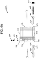
- FIGS. 4A-D show an embodiment of a dual DLFG 400 A-D similar to the devices described above.
- FIG. 4A shows an exploded view of a DLFG 400 A.
- FIG. 4B shows a DLFG ready for insertion in a carrier 400 B.
- FIG. 4C shows a DLFG in a carrier with a closed flapper 400 C.
- FIG. 4D shows a DLFG in a carrier with an open flapper 400 D.
- the exploded diagram shows a DLFG body 402 and a flapper 404 that is for articulation via a flapper hinge 409 and hinge pin or pins 407 that attach the flapper to the DLFG body.
- a first locking device 440 (see FIG. 4C ) is for fixing the flapper 404 in a closed position against an internal body lip 415 . In this position the flapper blocks the body through hole 412 .
- the first locking device includes a threaded shear pin(s) 405 inserted in hole(s) 416 in a perimeter of the body near the body end 414 . When the flapper is closed against the internal lip 415 of the body, a shear pin end 418 interferes with or overhangs the flapper such that the flapper blocks the body through hole.
- a second locking device 460 (see FIG. 4D ) includes an eccentric bore in the body 419 that is parallel to a body centerline x-x. This bore provides access to a flapper hinge hole 421 .
- a plunger 406 operating in the bore is urged by a spring 408 toward the flapper hinge hole. When the flapper hinge hole and the bore are aligned, the plunger end 423 enters the flapper hinge hole and locks the flapper in the open position.
- a threaded plug 410 is inserted at an end of the bore 425 to provide a spring rest.
- the DLFG 400 A is inserted 436 / 437 in a carrier 430 including a carrier pin end 432 and a carrier box end 434 .
- the pump forces flow entering the carrier pin end 438 , into the DLFG open flapper end, and then out the carrier box end 439 .
- FIG. 4C shows the DLFG 400 A with the flapper 404 in the closed and locked position.
- the flapper is locked by virtue of shear pin(s) preventing the flapper from opening.
- the flapper may be moved to the open position by ramming or by pressure such as pressure applied to the production tubing 204 at the surface. Ramming may be by a tool inserted in the production string, by a pump rod, or by a pump rotor during insertion of the rotor in a rod driven pump.
- FIG. 4D shows the DLFG 400 A with the flapper 404 in the open and locked position.
- the flapper is locked in the open position by the second locking device 460 which includes an end of the plunger 423 inserted in a flapper hinge hole.
- FIG. 5 shows an operation of the DLFG 500 .
- a string including the pump, bypass valve, flow gate with closed flapper, and production tubing string is lowered downhole into the casing.
- this string is lowered in the casing until the pump is seated at the bottom of the casing.
- a third step 506 the flow gate flapper 404 is opened.
- the first locking device 440 may be defeated and the flow gate opened by pressurization of the production tubing from the surface 508 which causes the shear pin(s) (e.g. 405 ) to fail.
- the flow gate may be opened by ramming 510 which also causes the shear pin(s) to fail.
- a ramming tool may be used or the rod of a rod driven pump may be used.
- a rod driven pump rod carrying a pump rotor may be used to ram the flapper open.
- a rod driven pump rod carrying a pump rotor may be used to ram the flapper open.
- a rod driven pump rod carrying a pump rotor may also be passed through the bypass valve 108 before it is seated in the pump.
- the flapper (e.g. 404 ) is open and a second locking device fixes the flapper in place.
- a plunger e.g. 406
- a DLFG body sidewall bore e.g. 419
- an end of the plunger e.g. 423
- a spring e.g. 408
- FIG. 6 shows operation of the DLFG during a pressurized reservoir event 600 .
- a string with a DLFG with a closed flapper is lowered into the casing 602 .
- the reservoir pressurizes the string, for example during the lowering operation 604 .
- the DLFG flapper is pressed against a DLFG body lip by shear pins and by reservoir pressure and so remains closed 606 .
- the DLFG flapper prevents oil from moving beyond the DLFG and toward the surface 608 .
- FIG. 7 shows operation of the DLFG during lowering of a string into the casing 700 .
- a string with a DLFG with a closed flapper is lowered into the casing 702 .
- oil in the casing tends to rise up into the string being lowered into the casing 704 .
- the DLFG flapper is pressed against a DLFG body lip by shear pins and by virtue of oil rising in the string 706 .
- the DLFG flapper prevents oil from moving beyond the DLFG and toward the surface 708 .
Landscapes
- Engineering & Computer Science (AREA)
- Life Sciences & Earth Sciences (AREA)
- Geology (AREA)
- Mining & Mineral Resources (AREA)
- General Engineering & Computer Science (AREA)
- Physics & Mathematics (AREA)
- Environmental & Geological Engineering (AREA)
- Fluid Mechanics (AREA)
- General Life Sciences & Earth Sciences (AREA)
- Geochemistry & Mineralogy (AREA)
- Mechanical Engineering (AREA)
- Rotary Pumps (AREA)
Abstract
Description
Claims (20)
Priority Applications (5)
| Application Number | Priority Date | Filing Date | Title |
|---|---|---|---|
| US15/962,280 US10844690B2 (en) | 2018-04-25 | 2018-04-25 | Dual lock flow gate |
| AU2018202946A AU2018202946A1 (en) | 2018-04-25 | 2018-04-27 | Dual lock flow gate |
| EP18171937.8A EP3561220B1 (en) | 2018-04-25 | 2018-05-11 | Dual lock flow gate |
| CA3005545A CA3005545A1 (en) | 2018-04-25 | 2018-05-22 | Dual lock flow gate |
| US16/009,022 US10941869B2 (en) | 2018-04-25 | 2018-06-14 | Dual lock flow gate |
Applications Claiming Priority (1)
| Application Number | Priority Date | Filing Date | Title |
|---|---|---|---|
| US15/962,280 US10844690B2 (en) | 2018-04-25 | 2018-04-25 | Dual lock flow gate |
Related Child Applications (1)
| Application Number | Title | Priority Date | Filing Date |
|---|---|---|---|
| US16/009,022 Continuation-In-Part US10941869B2 (en) | 2018-04-25 | 2018-06-14 | Dual lock flow gate |
Publications (2)
| Publication Number | Publication Date |
|---|---|
| US20190330958A1 US20190330958A1 (en) | 2019-10-31 |
| US10844690B2 true US10844690B2 (en) | 2020-11-24 |
Family
ID=62152494
Family Applications (1)
| Application Number | Title | Priority Date | Filing Date |
|---|---|---|---|
| US15/962,280 Active US10844690B2 (en) | 2018-04-25 | 2018-04-25 | Dual lock flow gate |
Country Status (4)
| Country | Link |
|---|---|
| US (1) | US10844690B2 (en) |
| EP (1) | EP3561220B1 (en) |
| AU (1) | AU2018202946A1 (en) |
| CA (1) | CA3005545A1 (en) |
Families Citing this family (11)
| Publication number | Priority date | Publication date | Assignee | Title |
|---|---|---|---|---|
| DK3803162T3 (en) * | 2018-06-05 | 2022-06-20 | Tdw Delaware Inc | CONTAINER CLOSURE DEVICE WITH ERROR-SAFE ERROR DETECTION BODY |
| US11261980B2 (en) * | 2020-03-12 | 2022-03-01 | Coil Solutions, Inc. | Apparatus and method for activation of flapper check valve |
| US11230906B2 (en) | 2020-06-02 | 2022-01-25 | Baker Hughes Oilfield Operations Llc | Locking backpressure valve |
| US11215031B2 (en) | 2020-06-02 | 2022-01-04 | Baker Hughes Oilfield Operations Llc | Locking backpressure valve with shiftable valve sleeve |
| US11215028B2 (en) | 2020-06-02 | 2022-01-04 | Baker Hughes Oilfield Operations Llc | Locking backpressure valve |
| US11359460B2 (en) | 2020-06-02 | 2022-06-14 | Baker Hughes Oilfield Operations Llc | Locking backpressure valve |
| US11365605B2 (en) | 2020-06-02 | 2022-06-21 | Baker Hughes Oilfield Operations Llc | Locking backpressure valve |
| US11215030B2 (en) | 2020-06-02 | 2022-01-04 | Baker Hughes Oilfield Operations Llc | Locking backpressure valve with shiftable valve seat |
| US11215026B2 (en) * | 2020-06-02 | 2022-01-04 | Baker Hughes Oilfield Operations Llc | Locking backpressure valve |
| US11913311B2 (en) * | 2020-06-30 | 2024-02-27 | Advanced Oil Tools, LLC | Flow control shuttle |
| US12188326B2 (en) * | 2023-04-24 | 2025-01-07 | Saudi Arabian Oil Company | Plug element facilitating well flowback |
Citations (30)
| Publication number | Priority date | Publication date | Assignee | Title |
|---|---|---|---|---|
| US2048088A (en) * | 1935-01-16 | 1936-07-21 | Wagner Henry | Backwater valve to be used on sewers, drains, and the like |
| US2654388A (en) * | 1944-11-07 | 1953-10-06 | Glass Ann Thesing | Backflow preventer |
| US2735498A (en) * | 1956-02-21 | Apparatus for automatically | ||
| US2812820A (en) * | 1953-05-26 | 1957-11-12 | Larkin Packer Company | Fill-up and cementing devices |
| US3494417A (en) * | 1968-01-29 | 1970-02-10 | Otis Eng Corp | Well tools |
| US3955592A (en) * | 1973-11-14 | 1976-05-11 | Guyton Glen B | Check valve |
| US4117860A (en) * | 1977-04-08 | 1978-10-03 | Carlin Jack M | Pressure differential flow retardant valve |
| US4154303A (en) * | 1978-02-13 | 1979-05-15 | The Dow Chemical Company | Valve assembly for controlling liquid flow in a wellbore |
| US4223697A (en) * | 1978-07-31 | 1980-09-23 | Judd Valve Company, Inc. | Check valve |
| US4291722A (en) * | 1979-11-02 | 1981-09-29 | Otis Engineering Corporation | Drill string safety and kill valve |
| US4597449A (en) * | 1984-04-20 | 1986-07-01 | Keeney L W | Method and apparatus for preventing fluid runovers from a well |
| US5056548A (en) * | 1990-10-12 | 1991-10-15 | Kf Industries, Inc. | Check valve assembly with removable seat |
| US5156183A (en) * | 1991-09-18 | 1992-10-20 | Scaramucci John P | Top-entry check valve having spring retainer |
| US5230390A (en) * | 1992-03-06 | 1993-07-27 | Baker Hughes Incorporated | Self-contained closure mechanism for a core barrel inner tube assembly |
| US5584315A (en) * | 1995-12-18 | 1996-12-17 | Ames Company, Inc. | Check valve assembly and method for mounting and installing check valves within a housing |
| US6397874B1 (en) * | 1997-12-19 | 2002-06-04 | Airvac, Inc. | Dual backflow check valve |
| US6446665B2 (en) * | 2000-03-23 | 2002-09-10 | Gabe Coscarella | Backwater valve |
| US6557645B1 (en) * | 2000-06-13 | 2003-05-06 | Grinnell Corporation | Dry pipe valve for fire protection sprinkler system |
| US6779947B1 (en) * | 2003-08-21 | 2004-08-24 | Kevin Buchanan | Gate systems and methods for regulating tidal flows |
| US7152622B2 (en) * | 2004-11-16 | 2006-12-26 | Valve Innovations, Llc | Check valve |
| US7673695B2 (en) * | 2006-06-02 | 2010-03-09 | The Reliable Automatic Sprinkler Co., Inc. | Dry pipe/deluge valve for automatic sprinkler systems |
| US7762336B2 (en) * | 2006-06-12 | 2010-07-27 | Weatherford/Lamb, Inc. | Flapper latch |
| US7784489B2 (en) * | 2005-08-11 | 2010-08-31 | Envirotech Pumpsystems, Inc. | Check valve for a self-priming pump |
| US8545190B2 (en) | 2010-04-23 | 2013-10-01 | Lawrence Osborne | Valve with shuttle for use in a flow management system |
| US9027654B2 (en) | 2010-04-23 | 2015-05-12 | Lawrence Osborne | Valve with shuttle |
| US9562418B2 (en) * | 2010-04-23 | 2017-02-07 | Lawrence Osborne | Valve with shuttle |
| US9759041B2 (en) | 2010-04-23 | 2017-09-12 | Lawrence Osborne | Valve with pump rotor passage for use in downhole production strings |
| US20180051532A1 (en) * | 2016-08-22 | 2018-02-22 | Roddie R. Smith | Frac Plug with Integrated Flapper Valve |
| US10100601B2 (en) * | 2014-12-16 | 2018-10-16 | Baker Hughes, A Ge Company, Llc | Downhole assembly having isolation tool and method |
| US10201723B2 (en) * | 2014-07-14 | 2019-02-12 | The Reliable Automatic Sprinkler Co., Inc. | Dry pipe/deluge valve for automatic sprinkler systems |
Family Cites Families (2)
| Publication number | Priority date | Publication date | Assignee | Title |
|---|---|---|---|---|
| CA2734546C (en) * | 2006-02-09 | 2014-08-05 | Weatherford/Lamb, Inc. | Managed pressure and/or temperature drilling system and method |
| AU2015252010B2 (en) * | 2010-05-24 | 2017-09-28 | Frank's International, Llc | Large bore auto-fill float equipment |
-
2018
- 2018-04-25 US US15/962,280 patent/US10844690B2/en active Active
- 2018-04-27 AU AU2018202946A patent/AU2018202946A1/en not_active Abandoned
- 2018-05-11 EP EP18171937.8A patent/EP3561220B1/en not_active Not-in-force
- 2018-05-22 CA CA3005545A patent/CA3005545A1/en active Pending
Patent Citations (30)
| Publication number | Priority date | Publication date | Assignee | Title |
|---|---|---|---|---|
| US2735498A (en) * | 1956-02-21 | Apparatus for automatically | ||
| US2048088A (en) * | 1935-01-16 | 1936-07-21 | Wagner Henry | Backwater valve to be used on sewers, drains, and the like |
| US2654388A (en) * | 1944-11-07 | 1953-10-06 | Glass Ann Thesing | Backflow preventer |
| US2812820A (en) * | 1953-05-26 | 1957-11-12 | Larkin Packer Company | Fill-up and cementing devices |
| US3494417A (en) * | 1968-01-29 | 1970-02-10 | Otis Eng Corp | Well tools |
| US3955592A (en) * | 1973-11-14 | 1976-05-11 | Guyton Glen B | Check valve |
| US4117860A (en) * | 1977-04-08 | 1978-10-03 | Carlin Jack M | Pressure differential flow retardant valve |
| US4154303A (en) * | 1978-02-13 | 1979-05-15 | The Dow Chemical Company | Valve assembly for controlling liquid flow in a wellbore |
| US4223697A (en) * | 1978-07-31 | 1980-09-23 | Judd Valve Company, Inc. | Check valve |
| US4291722A (en) * | 1979-11-02 | 1981-09-29 | Otis Engineering Corporation | Drill string safety and kill valve |
| US4597449A (en) * | 1984-04-20 | 1986-07-01 | Keeney L W | Method and apparatus for preventing fluid runovers from a well |
| US5056548A (en) * | 1990-10-12 | 1991-10-15 | Kf Industries, Inc. | Check valve assembly with removable seat |
| US5156183A (en) * | 1991-09-18 | 1992-10-20 | Scaramucci John P | Top-entry check valve having spring retainer |
| US5230390A (en) * | 1992-03-06 | 1993-07-27 | Baker Hughes Incorporated | Self-contained closure mechanism for a core barrel inner tube assembly |
| US5584315A (en) * | 1995-12-18 | 1996-12-17 | Ames Company, Inc. | Check valve assembly and method for mounting and installing check valves within a housing |
| US6397874B1 (en) * | 1997-12-19 | 2002-06-04 | Airvac, Inc. | Dual backflow check valve |
| US6446665B2 (en) * | 2000-03-23 | 2002-09-10 | Gabe Coscarella | Backwater valve |
| US6557645B1 (en) * | 2000-06-13 | 2003-05-06 | Grinnell Corporation | Dry pipe valve for fire protection sprinkler system |
| US6779947B1 (en) * | 2003-08-21 | 2004-08-24 | Kevin Buchanan | Gate systems and methods for regulating tidal flows |
| US7152622B2 (en) * | 2004-11-16 | 2006-12-26 | Valve Innovations, Llc | Check valve |
| US7784489B2 (en) * | 2005-08-11 | 2010-08-31 | Envirotech Pumpsystems, Inc. | Check valve for a self-priming pump |
| US7673695B2 (en) * | 2006-06-02 | 2010-03-09 | The Reliable Automatic Sprinkler Co., Inc. | Dry pipe/deluge valve for automatic sprinkler systems |
| US7762336B2 (en) * | 2006-06-12 | 2010-07-27 | Weatherford/Lamb, Inc. | Flapper latch |
| US8545190B2 (en) | 2010-04-23 | 2013-10-01 | Lawrence Osborne | Valve with shuttle for use in a flow management system |
| US9027654B2 (en) | 2010-04-23 | 2015-05-12 | Lawrence Osborne | Valve with shuttle |
| US9562418B2 (en) * | 2010-04-23 | 2017-02-07 | Lawrence Osborne | Valve with shuttle |
| US9759041B2 (en) | 2010-04-23 | 2017-09-12 | Lawrence Osborne | Valve with pump rotor passage for use in downhole production strings |
| US10201723B2 (en) * | 2014-07-14 | 2019-02-12 | The Reliable Automatic Sprinkler Co., Inc. | Dry pipe/deluge valve for automatic sprinkler systems |
| US10100601B2 (en) * | 2014-12-16 | 2018-10-16 | Baker Hughes, A Ge Company, Llc | Downhole assembly having isolation tool and method |
| US20180051532A1 (en) * | 2016-08-22 | 2018-02-22 | Roddie R. Smith | Frac Plug with Integrated Flapper Valve |
Also Published As
| Publication number | Publication date |
|---|---|
| EP3561220B1 (en) | 2020-12-09 |
| AU2018202946A1 (en) | 2019-11-14 |
| US20190330958A1 (en) | 2019-10-31 |
| CA3005545A1 (en) | 2019-10-25 |
| EP3561220A1 (en) | 2019-10-30 |
Similar Documents
| Publication | Publication Date | Title |
|---|---|---|
| US10844690B2 (en) | Dual lock flow gate | |
| US10941869B2 (en) | Dual lock flow gate | |
| US4427070A (en) | Circulating and pressure equalizing sub | |
| US8789602B2 (en) | Ball drop module | |
| US3696868A (en) | Well flow control valves and well systems utilizing the same | |
| US8016035B2 (en) | Chemical injection check valve incorporated into a tubing retrievable safety valve | |
| EP3976921B1 (en) | Wellhead assembly valve systems and methods | |
| US20130189123A1 (en) | Hydraulic Powered Downhole Pump | |
| US10458203B2 (en) | Pressure cycle actuated injection valve | |
| US9822606B2 (en) | Standing injection valve with hydraulically dampened valve closure | |
| US11261978B2 (en) | Annulus safety valve system and method | |
| US11773689B2 (en) | Surge flow mitigation tool, system and method | |
| US9598928B2 (en) | Casing hanger lockdown tools | |
| US4603740A (en) | Subsurface safety valve | |
| US10900326B2 (en) | Back flow restriction system and methodology for injection well | |
| US20170335656A1 (en) | Controlled opening valve | |
| US9903181B2 (en) | Communication and lock open safety valve system and method | |
| US20170016294A1 (en) | Casing hanger lockdown tools | |
| US10156121B2 (en) | Testable backpressure valve system | |
| US10571027B2 (en) | Metal ring seal and improved profile selective system for downhole tools | |
| US20170101842A1 (en) | Completion System with External Gate Valve | |
| EP2376740B1 (en) | Wellhead downhole line communication arrangement | |
| MX2013006623A (en) | Downhole completion. | |
| CA2948325C (en) | Casing hanger lockdown tools | |
| GB2497408A (en) | Lock assembly for hydraulic fracing valve |
Legal Events
| Date | Code | Title | Description |
|---|---|---|---|
| FEPP | Fee payment procedure |
Free format text: ENTITY STATUS SET TO UNDISCOUNTED (ORIGINAL EVENT CODE: BIG.); ENTITY STATUS OF PATENT OWNER: SMALL ENTITY |
|
| FEPP | Fee payment procedure |
Free format text: ENTITY STATUS SET TO SMALL (ORIGINAL EVENT CODE: SMAL); ENTITY STATUS OF PATENT OWNER: SMALL ENTITY |
|
| STPP | Information on status: patent application and granting procedure in general |
Free format text: NON FINAL ACTION MAILED |
|
| STPP | Information on status: patent application and granting procedure in general |
Free format text: RESPONSE TO NON-FINAL OFFICE ACTION ENTERED AND FORWARDED TO EXAMINER |
|
| STPP | Information on status: patent application and granting procedure in general |
Free format text: FINAL REJECTION MAILED |
|
| STPP | Information on status: patent application and granting procedure in general |
Free format text: NOTICE OF ALLOWANCE MAILED -- APPLICATION RECEIVED IN OFFICE OF PUBLICATIONS |
|
| STPP | Information on status: patent application and granting procedure in general |
Free format text: PUBLICATIONS -- ISSUE FEE PAYMENT RECEIVED |
|
| STCF | Information on status: patent grant |
Free format text: PATENTED CASE |
|
| MAFP | Maintenance fee payment |
Free format text: PAYMENT OF MAINTENANCE FEE, 4TH YR, SMALL ENTITY (ORIGINAL EVENT CODE: M2551); ENTITY STATUS OF PATENT OWNER: SMALL ENTITY Year of fee payment: 4 |