US10842402B2 - Determination system, control signal output system, rehabilitation system, determination method, control signal output method, and recording medium - Google Patents
Determination system, control signal output system, rehabilitation system, determination method, control signal output method, and recording medium Download PDFInfo
- Publication number
- US10842402B2 US10842402B2 US14/965,597 US201514965597A US10842402B2 US 10842402 B2 US10842402 B2 US 10842402B2 US 201514965597 A US201514965597 A US 201514965597A US 10842402 B2 US10842402 B2 US 10842402B2
- Authority
- US
- United States
- Prior art keywords
- user
- electrode
- ear hole
- voltage signal
- head
- Prior art date
- Legal status (The legal status is an assumption and is not a legal conclusion. Google has not performed a legal analysis and makes no representation as to the accuracy of the status listed.)
- Active, expires
Links
- 238000000034 method Methods 0.000 title claims description 26
- 230000008859 change Effects 0.000 claims abstract description 64
- 210000003128 head Anatomy 0.000 claims description 93
- 210000001595 mastoid Anatomy 0.000 claims description 27
- 238000012545 processing Methods 0.000 claims description 19
- 210000000613 ear canal Anatomy 0.000 claims description 12
- 238000004590 computer program Methods 0.000 claims description 11
- 238000005259 measurement Methods 0.000 description 81
- 238000003384 imaging method Methods 0.000 description 70
- 210000004556 brain Anatomy 0.000 description 38
- 238000001514 detection method Methods 0.000 description 32
- 238000004070 electrodeposition Methods 0.000 description 17
- 238000002474 experimental method Methods 0.000 description 17
- 238000010586 diagram Methods 0.000 description 14
- 206010033799 Paralysis Diseases 0.000 description 12
- 238000012360 testing method Methods 0.000 description 10
- 238000004891 communication Methods 0.000 description 8
- 230000008901 benefit Effects 0.000 description 6
- 230000006870 function Effects 0.000 description 6
- 210000005069 ears Anatomy 0.000 description 5
- 230000003183 myoelectrical effect Effects 0.000 description 5
- 230000000694 effects Effects 0.000 description 4
- 210000003205 muscle Anatomy 0.000 description 4
- 230000008569 process Effects 0.000 description 4
- 208000006011 Stroke Diseases 0.000 description 3
- 230000007423 decrease Effects 0.000 description 2
- 239000000284 extract Substances 0.000 description 2
- 210000005036 nerve Anatomy 0.000 description 2
- 210000004243 sweat Anatomy 0.000 description 2
- GTKRFUAGOKINCA-UHFFFAOYSA-M chlorosilver;silver Chemical compound [Ag].[Ag]Cl GTKRFUAGOKINCA-UHFFFAOYSA-M 0.000 description 1
- 239000004973 liquid crystal related substance Substances 0.000 description 1
- 239000000463 material Substances 0.000 description 1
- 230000004048 modification Effects 0.000 description 1
- 238000012986 modification Methods 0.000 description 1
- 230000035699 permeability Effects 0.000 description 1
- 230000000284 resting effect Effects 0.000 description 1
- 238000005070 sampling Methods 0.000 description 1
- 239000004065 semiconductor Substances 0.000 description 1
- 230000000638 stimulation Effects 0.000 description 1
- YMBCJWGVCUEGHA-UHFFFAOYSA-M tetraethylammonium chloride Chemical compound [Cl-].CC[N+](CC)(CC)CC YMBCJWGVCUEGHA-UHFFFAOYSA-M 0.000 description 1
- 210000003454 tympanic membrane Anatomy 0.000 description 1
Images


Classifications
-
- A61B5/0478—
-
- A—HUMAN NECESSITIES
- A61—MEDICAL OR VETERINARY SCIENCE; HYGIENE
- A61B—DIAGNOSIS; SURGERY; IDENTIFICATION
- A61B5/00—Measuring for diagnostic purposes; Identification of persons
- A61B5/24—Detecting, measuring or recording bioelectric or biomagnetic signals of the body or parts thereof
- A61B5/316—Modalities, i.e. specific diagnostic methods
- A61B5/369—Electroencephalography [EEG]
-
- A—HUMAN NECESSITIES
- A61—MEDICAL OR VETERINARY SCIENCE; HYGIENE
- A61B—DIAGNOSIS; SURGERY; IDENTIFICATION
- A61B5/00—Measuring for diagnostic purposes; Identification of persons
- A61B5/68—Arrangements of detecting, measuring or recording means, e.g. sensors, in relation to patient
- A61B5/6801—Arrangements of detecting, measuring or recording means, e.g. sensors, in relation to patient specially adapted to be attached to or worn on the body surface
- A61B5/6813—Specially adapted to be attached to a specific body part
- A61B5/6814—Head
- A61B5/6815—Ear
- A61B5/6817—Ear canal
-
- A61B5/048—
-
- A—HUMAN NECESSITIES
- A61—MEDICAL OR VETERINARY SCIENCE; HYGIENE
- A61B—DIAGNOSIS; SURGERY; IDENTIFICATION
- A61B5/00—Measuring for diagnostic purposes; Identification of persons
- A61B5/24—Detecting, measuring or recording bioelectric or biomagnetic signals of the body or parts thereof
- A61B5/25—Bioelectric electrodes therefor
- A61B5/279—Bioelectric electrodes therefor specially adapted for particular uses
- A61B5/291—Bioelectric electrodes therefor specially adapted for particular uses for electroencephalography [EEG]
-
- A—HUMAN NECESSITIES
- A61—MEDICAL OR VETERINARY SCIENCE; HYGIENE
- A61B—DIAGNOSIS; SURGERY; IDENTIFICATION
- A61B5/00—Measuring for diagnostic purposes; Identification of persons
- A61B5/24—Detecting, measuring or recording bioelectric or biomagnetic signals of the body or parts thereof
- A61B5/316—Modalities, i.e. specific diagnostic methods
- A61B5/369—Electroencephalography [EEG]
- A61B5/372—Analysis of electroencephalograms
- A61B5/374—Detecting the frequency distribution of signals, e.g. detecting delta, theta, alpha, beta or gamma waves
-
- A—HUMAN NECESSITIES
- A61—MEDICAL OR VETERINARY SCIENCE; HYGIENE
- A61H—PHYSICAL THERAPY APPARATUS, e.g. DEVICES FOR LOCATING OR STIMULATING REFLEX POINTS IN THE BODY; ARTIFICIAL RESPIRATION; MASSAGE; BATHING DEVICES FOR SPECIAL THERAPEUTIC OR HYGIENIC PURPOSES OR SPECIFIC PARTS OF THE BODY
- A61H1/00—Apparatus for passive exercising; Vibrating apparatus; Chiropractic devices, e.g. body impacting devices, external devices for briefly extending or aligning unbroken bones
- A61H1/02—Stretching or bending or torsioning apparatus for exercising
- A61H1/0237—Stretching or bending or torsioning apparatus for exercising for the lower limbs
- A61H1/0266—Foot
-
- A—HUMAN NECESSITIES
- A61—MEDICAL OR VETERINARY SCIENCE; HYGIENE
- A61H—PHYSICAL THERAPY APPARATUS, e.g. DEVICES FOR LOCATING OR STIMULATING REFLEX POINTS IN THE BODY; ARTIFICIAL RESPIRATION; MASSAGE; BATHING DEVICES FOR SPECIAL THERAPEUTIC OR HYGIENIC PURPOSES OR SPECIFIC PARTS OF THE BODY
- A61H1/00—Apparatus for passive exercising; Vibrating apparatus; Chiropractic devices, e.g. body impacting devices, external devices for briefly extending or aligning unbroken bones
- A61H1/02—Stretching or bending or torsioning apparatus for exercising
- A61H1/0274—Stretching or bending or torsioning apparatus for exercising for the upper limbs
- A61H1/0285—Hand
-
- G06F19/325—
-
- G—PHYSICS
- G16—INFORMATION AND COMMUNICATION TECHNOLOGY [ICT] SPECIALLY ADAPTED FOR SPECIFIC APPLICATION FIELDS
- G16H—HEALTHCARE INFORMATICS, i.e. INFORMATION AND COMMUNICATION TECHNOLOGY [ICT] SPECIALLY ADAPTED FOR THE HANDLING OR PROCESSING OF MEDICAL OR HEALTHCARE DATA
- G16H20/00—ICT specially adapted for therapies or health-improving plans, e.g. for handling prescriptions, for steering therapy or for monitoring patient compliance
- G16H20/30—ICT specially adapted for therapies or health-improving plans, e.g. for handling prescriptions, for steering therapy or for monitoring patient compliance relating to physical therapies or activities, e.g. physiotherapy, acupressure or exercising
-
- A—HUMAN NECESSITIES
- A61—MEDICAL OR VETERINARY SCIENCE; HYGIENE
- A61B—DIAGNOSIS; SURGERY; IDENTIFICATION
- A61B2505/00—Evaluating, monitoring or diagnosing in the context of a particular type of medical care
- A61B2505/09—Rehabilitation or training
-
- A—HUMAN NECESSITIES
- A61—MEDICAL OR VETERINARY SCIENCE; HYGIENE
- A61B—DIAGNOSIS; SURGERY; IDENTIFICATION
- A61B5/00—Measuring for diagnostic purposes; Identification of persons
- A61B5/72—Signal processing specially adapted for physiological signals or for diagnostic purposes
- A61B5/7271—Specific aspects of physiological measurement analysis
- A61B5/7275—Determining trends in physiological measurement data; Predicting development of a medical condition based on physiological measurements, e.g. determining a risk factor
-
- A—HUMAN NECESSITIES
- A61—MEDICAL OR VETERINARY SCIENCE; HYGIENE
- A61H—PHYSICAL THERAPY APPARATUS, e.g. DEVICES FOR LOCATING OR STIMULATING REFLEX POINTS IN THE BODY; ARTIFICIAL RESPIRATION; MASSAGE; BATHING DEVICES FOR SPECIAL THERAPEUTIC OR HYGIENIC PURPOSES OR SPECIFIC PARTS OF THE BODY
- A61H2201/00—Characteristics of apparatus not provided for in the preceding codes
- A61H2201/12—Driving means
- A61H2201/1207—Driving means with electric or magnetic drive
-
- A—HUMAN NECESSITIES
- A61—MEDICAL OR VETERINARY SCIENCE; HYGIENE
- A61H—PHYSICAL THERAPY APPARATUS, e.g. DEVICES FOR LOCATING OR STIMULATING REFLEX POINTS IN THE BODY; ARTIFICIAL RESPIRATION; MASSAGE; BATHING DEVICES FOR SPECIAL THERAPEUTIC OR HYGIENIC PURPOSES OR SPECIFIC PARTS OF THE BODY
- A61H2201/00—Characteristics of apparatus not provided for in the preceding codes
- A61H2201/16—Physical interface with patient
- A61H2201/1602—Physical interface with patient kind of interface, e.g. head rest, knee support or lumbar support
- A61H2201/1635—Hand or arm, e.g. handle
-
- A—HUMAN NECESSITIES
- A61—MEDICAL OR VETERINARY SCIENCE; HYGIENE
- A61H—PHYSICAL THERAPY APPARATUS, e.g. DEVICES FOR LOCATING OR STIMULATING REFLEX POINTS IN THE BODY; ARTIFICIAL RESPIRATION; MASSAGE; BATHING DEVICES FOR SPECIAL THERAPEUTIC OR HYGIENIC PURPOSES OR SPECIFIC PARTS OF THE BODY
- A61H2201/00—Characteristics of apparatus not provided for in the preceding codes
- A61H2201/16—Physical interface with patient
- A61H2201/1602—Physical interface with patient kind of interface, e.g. head rest, knee support or lumbar support
- A61H2201/164—Feet or leg, e.g. pedal
-
- A—HUMAN NECESSITIES
- A61—MEDICAL OR VETERINARY SCIENCE; HYGIENE
- A61H—PHYSICAL THERAPY APPARATUS, e.g. DEVICES FOR LOCATING OR STIMULATING REFLEX POINTS IN THE BODY; ARTIFICIAL RESPIRATION; MASSAGE; BATHING DEVICES FOR SPECIAL THERAPEUTIC OR HYGIENIC PURPOSES OR SPECIFIC PARTS OF THE BODY
- A61H2201/00—Characteristics of apparatus not provided for in the preceding codes
- A61H2201/16—Physical interface with patient
- A61H2201/1602—Physical interface with patient kind of interface, e.g. head rest, knee support or lumbar support
- A61H2201/165—Wearable interfaces
-
- A—HUMAN NECESSITIES
- A61—MEDICAL OR VETERINARY SCIENCE; HYGIENE
- A61H—PHYSICAL THERAPY APPARATUS, e.g. DEVICES FOR LOCATING OR STIMULATING REFLEX POINTS IN THE BODY; ARTIFICIAL RESPIRATION; MASSAGE; BATHING DEVICES FOR SPECIAL THERAPEUTIC OR HYGIENIC PURPOSES OR SPECIFIC PARTS OF THE BODY
- A61H2201/00—Characteristics of apparatus not provided for in the preceding codes
- A61H2201/50—Control means thereof
- A61H2201/5007—Control means thereof computer controlled
-
- A—HUMAN NECESSITIES
- A61—MEDICAL OR VETERINARY SCIENCE; HYGIENE
- A61H—PHYSICAL THERAPY APPARATUS, e.g. DEVICES FOR LOCATING OR STIMULATING REFLEX POINTS IN THE BODY; ARTIFICIAL RESPIRATION; MASSAGE; BATHING DEVICES FOR SPECIAL THERAPEUTIC OR HYGIENIC PURPOSES OR SPECIFIC PARTS OF THE BODY
- A61H2230/00—Measuring physical parameters of the user
- A61H2230/04—Heartbeat characteristics, e.g. E.G.C., blood pressure modulation
- A61H2230/045—Heartbeat characteristics, e.g. E.G.C., blood pressure modulation used as a control parameter for the apparatus
-
- A—HUMAN NECESSITIES
- A61—MEDICAL OR VETERINARY SCIENCE; HYGIENE
- A61H—PHYSICAL THERAPY APPARATUS, e.g. DEVICES FOR LOCATING OR STIMULATING REFLEX POINTS IN THE BODY; ARTIFICIAL RESPIRATION; MASSAGE; BATHING DEVICES FOR SPECIAL THERAPEUTIC OR HYGIENIC PURPOSES OR SPECIFIC PARTS OF THE BODY
- A61H2230/00—Measuring physical parameters of the user
- A61H2230/08—Other bio-electrical signals
- A61H2230/10—Electroencephalographic signals
- A61H2230/105—Electroencephalographic signals used as a control parameter for the apparatus
-
- G—PHYSICS
- G16—INFORMATION AND COMMUNICATION TECHNOLOGY [ICT] SPECIALLY ADAPTED FOR SPECIFIC APPLICATION FIELDS
- G16H—HEALTHCARE INFORMATICS, i.e. INFORMATION AND COMMUNICATION TECHNOLOGY [ICT] SPECIALLY ADAPTED FOR THE HANDLING OR PROCESSING OF MEDICAL OR HEALTHCARE DATA
- G16H40/00—ICT specially adapted for the management or administration of healthcare resources or facilities; ICT specially adapted for the management or operation of medical equipment or devices
- G16H40/60—ICT specially adapted for the management or administration of healthcare resources or facilities; ICT specially adapted for the management or operation of medical equipment or devices for the operation of medical equipment or devices
- G16H40/63—ICT specially adapted for the management or administration of healthcare resources or facilities; ICT specially adapted for the management or operation of medical equipment or devices for the operation of medical equipment or devices for local operation
Definitions
- the present disclosure relates to a technique for measuring event-related desynchronization (ERD) in brain waves that is induced by a motor intention.
- ERP event-related desynchronization
- ERD is a phenomenon in which, in the case of intending to perform a movement or actually performing a movement, a voltage strength in the ⁇ band and/or a voltage strength in the ⁇ band of brain waves at the vicinity of the motor area of the head decreases compared to that in a resting state. It is known that the frequency band in which ERD occurs varies among individuals, that is, ERD may occur only in the ⁇ band, only in the ⁇ band, or in both of the ⁇ and ⁇ bands.
- Japanese Unexamined Patent Application Publication No. 2012-217721 discloses a rehabilitation apparatus that measures an electroencephalogram (EEG) signal at the vicinity of the motor area corresponding to a target portion of rehabilitation, detects ERD on the basis of a change over time in signal strength of a certain frequency component of the measured EEG signal, and thereby moves an attachment attached to a paralyzed portion. Specifically, the rehabilitation apparatus determines, at an interval of 50 ms, whether or not ERD exists and, if ERD is detected, immediately operates a motor to give feedback to a patient. Accordingly, the time lag between a motor intention and an actual movement can be reduced and thereby effective rehabilitation can be performed.
- EEG electroencephalogram
- ERD detection is a first important step in brain machine interface (BMI) rehabilitation using an electroencephalogram (EEG), and thus it is considered that low ERD detection accuracy may result in a decrease in rehabilitation effect.
- BMI brain machine interface
- EEG electroencephalogram
- One non-limiting and exemplary embodiment provides a determination system for detecting ERD with high accuracy.
- the techniques disclosed here feature a determination system including a head electrode that is located on a left head portion of a user when an intention of the user to move a portion on a right side of a body of the user is detected and that is located on a right head portion of the user when an intention of the user to move a portion on a left side of the body of the user is detected; an ear hole electrode that is located in an ear hole of the user; an electroencephalogram signal measurer that obtains a voltage between the head electrode and the ear hole electrode; and a determiner that determines whether or not a change in the voltage includes the intention of the user to move the portion on the right side of the body of the user or the intention of the user to move the portion on the left side of the body of the user.
- ERD can be detected with high accuracy.
- the computer-readable recording medium includes a nonvolatile recording medium, for example, a compact disc-read only memory (CD-ROM) or the like.
- FIG. 1 is a diagram illustrating a shape of a right ear
- FIG. 2A is a schematic diagram illustrating locations of head electrodes under a right-hand condition
- FIG. 2B is a diagram illustrating electrode locations according to the international 10-20 system
- FIG. 3A is a diagram illustrating ear molds for right and left ears made to measure brain waves in ear holes
- FIG. 3B is a diagram illustrating ear molds for right and left ears made to measure brain waves in ear holes
- FIG. 4 is a diagram illustrating electrode positions and electrode numbers for individual conditions
- FIG. 5 is a diagram illustrating, as an example of brain waveforms in measurement, a voltage waveform between an electrode at a certain position and a reference electrode and a voltage waveform between an electrode in a front portion of a left ear hole and the reference electrode under a right-hand condition;
- FIG. 6 illustrates, as an example of experiment results, the ERD change rates in the ⁇ waveband and the ERD change rates in the ⁇ waveband in individual trials for individual measurement electrodes, calculated from the voltages between the individual measurement electrodes and the reference electrode under the right-hand condition;
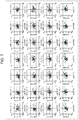
- FIG. 7 illustrates the ERD change rates in the ⁇ waveband and the ERD change rates in the ⁇ waveband calculated from the voltages between measurement electrodes in individual combinations of two different measurement electrodes under the right-hand condition;
- FIG. 8 is a diagram illustrating the number of ERD detections (an average value in the right-hand condition and left-hand condition) in which it is determined that ERD exists in an imaging section on the basis of ERD change rates in the ⁇ waveband calculated from potentials between the reference electrode and the individual measurement electrodes;
- FIG. 9 is a diagram illustrating the number of ERD detections (an average value in the right-hand condition and left-hand condition) Avr in which it is determined that ERD exists on the basis of ERD change rates in the ⁇ waveband calculated from differential waveforms of combinations of the individual measurement electrodes;
- FIG. 10 is a configuration diagram illustrating functional blocks of an ERD measurement system according to an exemplary embodiment
- FIG. 11 is a diagram illustrating the configuration of the ERD measurement system and an environment in which the system is used according to an exemplary embodiment
- FIG. 12 is a flowchart illustrating a procedure of processing performed by the ERD measurement system
- FIG. 13 is a diagram illustrating an example configuration of a rehabilitation system
- FIG. 14 is a diagram illustrating an environment in which the rehabilitation system is used.
- FIG. 15 is a flowchart illustrating a procedure of processing performed by a control signal output system of the rehabilitation system.
- FIG. 16 is a diagram illustrating an example of the hardware configuration of an ERD measurement apparatus.
- an “ear hole” is a region including a tympanic membrane, an external auditory canal, and an auricular concha.
- An example of the ear hole is a region including a region H that includes an auricular concha and an external auditory canal, a cavum conchae A 1 , and an intertragic notch A 2 (see FIG. 1 ).
- the ear hole may be a hollow portion included in a region B illustrated in FIG. 1 .
- the right side of a body is a portion on the right side of a human body and includes, for example, a right head portion, a right ear, a right mastoid, a right ear hole, a right hand, a right arm, and a right foot.
- the left side of a body is a portion on the left side of a human body and includes, for example, a left head portion, a left ear, a left mastoid, a left ear hole, a left hand, a left arm, and a left foot.
- Cerebral stroke may leave a patient with a paralyzed hand or foot. The patient undergoes rehabilitation to improve the paralysis.
- Paralysis has at least the following two degrees (A) and (B). In accordance with the degrees of paralysis, different rehabilitation programs are proposed.
- a motor intention of the patient is extracted by using ERD in brain waves as an index, an attachment attached to the paralyzed portion is moved by a motor or the like, and thereby the paralyzed portion is moved.
- This method is called brain machine interface (BMI) rehabilitation using an electroencephalogram (EEG).
- An EEG signal acquisition system detects ERD with high accuracy by using a change in the potential difference between one measurement electrode located on a head and one measurement electrode located in an ear hole.
- the present disclosure is based on an ERD detection characteristic that has been found out through experiments conducted by the inventors. Before describing an exemplary embodiment of the present disclosure, a detailed description will be given of the experiments conducted by the inventors, the results of the experiments, and knowledge obtained through the experiments. After that, a description will be given of an outline of an ERD measurement system according to an embodiment and the configuration and operation thereof.
- the inventors conducted ERD measurement experiments by locating electrodes in a motor area of a head and an ear hole in order to specify the electrode positions where ERD induced by a motor intention can be optimally detected.
- the ERD detection rate is higher in the case of using, as an index, a change in a potential difference in brain waves measured at one point near the motor area of the head and one point in the ear hole, than in the case of using a change in a potential difference in brain waves measured at two points near the motor area of the head.
- the higher accuracy of ERD detection may result in higher efficiency of rehabilitation in which a motor intention of a user is extracted by using ERD as an index, such as a BMI rehabilitation system using an EEG.
- test subject was an adult male (36 years old) with no history of cerebral stroke.
- the test subject was requested to alternately repeat five-second relaxation (referred to as a relax section) and five-second finger extension imaging (referred to as an imaging section) in accordance with a sound stimulation indicating the timing at which tasks are to be changed.
- An instruction was provided to the test subject to loosen up the whole body as much as possible and relax in the relax section and to image extending fingers slowly for five seconds while keeping the hands squeezed lightly in the imaging section.
- a right-hand condition of performing finger extension imaging of the right hand and a left-hand condition of performing finger extension imaging of the left hand were provided. Twenty repetitions were regarded as one set, and three sets of experiments were performed for each condition.
- one set includes twenty processes (twenty trials). Three sets of experiments under the right-hand condition and three sets of experiments under the left-hand condition were performed.
- FIG. 2A schematically illustrates the locations of head electrodes under the right-hand condition.
- head electrodes were attached to a position C 3 specified by the international 10-20 system and a position 20 mm to the left of the position C 3 (referred to as a position C 3 L).
- FIG. 2B illustrates the electrode locations specified by the international 10-20 system. The position C 3 L is also illustrated for reference.
- a reference electrode R was attached to a left mastoid (represented by R in FIG. 2A ) on the same side as the head electrodes, whereas an earth (ground) G was attached to a right mastoid (represented by G in FIG. 2A ) on the side opposite to the head electrodes.
- FIG. 2 B also illustrates the position C 4 L for reference.
- a reference electrode was attached to the right mastoid on the same side as the head electrodes, whereas an earth was attached to the left mastoid on the side opposite to the head electrodes.
- a mastoid is a portion below an ear (a portion below the base of the ear).
- FIG. 1 illustrates a position M of the mastoid.
- FIGS. 3A and 3B each illustrate ear molds for the right and left ears made to measure brain waves in the ear holes.
- the ear molds were made on the basis of casts of the ears of the test subject taken in advance.
- each of the right and left ear molds has ear hole electrodes E located at three positions.
- the ear hole electrodes E are made of a silver-silver chloride material having a diameter of 3 mm.
- Each ear mold has an ear hole electrode at a position that comes into contact with the auricular concha, an ear hole electrode at a position that comes into contact with the front side (face side) above a first curve of the external auditory canal, and an ear hole electrode at a position that comes into contact with the upper side (head top side) thereof.
- the positions of the ear hole electrodes are not limited thereto, but at least need to be the positions at which the ear mold comes into contact with the ear hole.
- a terminal T illustrated in FIG. 3A is connected to an operation amplifier circuit (not illustrated) for measuring a potential.
- a hole was intentionally provided at a cross-sectional portion of the external auditory canal for two reasons.
- One reason is to ensure the permeability of the ear hole and suppress an influence of sweat on measurement of brain waves.
- the distances between electrodes are short. This may cause a short circuit of the electrodes via sweat. In this case, brain waves are not correctly recorded.
- the other reason is to pass external sound information.
- a physical therapist communicates with a user, for example, informs the user of the progress or gives the user encouraging words. Also, notification about the start timings of a relax section and an imaging section can be given by using sound information.
- An example of the diameter of the through hole F is about 3 mm or more and 5 mm or less. The diameter of the through hole F may be larger or smaller.
- FIG. 4 illustrates electrode positions and electrode numbers for each condition.
- the head electrodes correspond to electrode numbers 1 and 2
- the three ear hole electrodes of each of the right and left ears correspond to electrode numbers 3 to 8 .
- the positions of the measurement electrodes for the head and ear holes and the positions of the reference electrode and earth electrode for the left-hand condition are opposite to those for the right-hand condition. Accordingly, data for the right-hand condition and the left-hand condition can be analyzed for each electrode number.
- Polymate AP1124 (made by TEAC) was used as an electroencephalograph. A sampling frequency of 1000 Hz and a time constant of 1 second were used. A band-path filter of 1 to 30 Hz in offline was applied.
- the presence/absence of ERD was determined on the basis of a brain waveform (change in voltage) obtained through measurement.
- a brain waveform change in voltage
- data for the first one second and the last one second in five seconds was removed, and frequency analysis was performed on data for the residual three seconds.
- an average value of intensity in the ⁇ waveband of brain waves in the relax section, an average value of intensity in the ⁇ waveband of brain waves in the relax section, an average value of intensity in the ⁇ waveband of brain waves in the imaging section, and an average value of intensity in the ⁇ waveband of brain waves in the imaging section were calculated.
- the ⁇ waveband ranged from 8 to 12 Hz
- the ⁇ waveband ranged from 13 to 26 Hz.
- ERD change rates of electric signals (potential difference signals) between the individual measurement electrodes and the reference electrode were calculated and (2) the ERD change rates of electric signals (potential difference signals) between the measurement electrodes in individual 28 combinations, each combination including two different measurement electrodes, were calculated.
- the ERD change rate is a positive value or zero, it was determined that ERD occurred in the imaging section.
- the determination result about the presence/absence of ERD was compared with a determination result obtained by using an electric signal (potential difference signal) between two electrodes on the head at typical electrode positions in a method according to the related art. Note that a potential difference may be referred to as a voltage.
- FIG. 5 illustrates, as an example of brain waveforms in measurement, a voltage waveform between the electrode at the position C 3 and the reference electrode and a voltage waveform between the electrode in the front portion of the left ear hole and the reference electrode under the right-hand condition.
- FIG. 5 illustrates voltage waveforms in a relax section and an imaging section following the relax section. Compared to the amplitude of the voltage waveform between the electrode at the position C 3 and the reference electrode, the amplitude of the voltage waveform between the electrode in the front portion of the left ear hole and the reference electrode is small. As a whole, the voltage waveform between the electrode at the position C 3 and the reference electrode is similar to the voltage waveform between the electrode in the front portion of the left ear hole and the reference electrode.
- FIG. 6 illustrates, as an example of experiment results, the ERD change rates in the ⁇ waveband and the ERD change rates in the ⁇ waveband in individual trials for individual measurement electrodes, calculated from the voltages between the individual measurement electrodes and the reference electrode under the right-hand condition.
- the number of trials is 60 (60 processes).
- the number of the measurement electrode (electrode position) is indicated on the upper side of each graph.
- FIG. 7 illustrates the ERD change rates in the ⁇ waveband and the ERD change rates in the ⁇ waveband calculated from the voltages between measurement electrodes in individual combinations of two different measurement electrodes (the number of combinations is 28) under the right-hand condition.
- Each graph includes the ERD change rates in 60 trials (60 processes).
- the number of a combination of measurement electrodes is indicated on the upper side of each graph.
- the horizontal axis represents the ERD change rate in the ⁇ waveband and the vertical axis represents the ERD change rate in the ⁇ waveband. In the horizontal or vertical axis, if the change rate is lower than zero, it can be determined that ERD was detected.
- the test subject of the ERD measurement experiments conducted by the inventors has a higher ERD change rate in the ⁇ waveband than in the ⁇ waveband.
- ERD occurs in either or both of the ⁇ waveband and the ⁇ waveband depending on a test subject.
- the vertical axis represents an average value of the number of ERD detections under the right-hand condition and the number of ERD detections under the left-hand condition
- the numbers along the horizontal axis represent the electrode numbers illustrated in FIG. 4 .
- the number of ERD detections under the right-hand condition is the number of detections in which the individual electrodes are attached to the test subject in accordance with the right-hand condition illustrated in FIG. 4 and it is determined that ERD exists in the imaging section on the basis of the ERD change rates in the ⁇ waveband calculated from the voltages between the individual measurement electrodes and the reference electrode.
- the number of ERD detections under the left-hand condition is the number of detections in which the individual electrodes are attached to the test subject in accordance with the left-hand condition illustrated in FIG. 4 and it is determined that ERD exists in the imaging section on the basis of the ERD change rates in the ⁇ waveband calculated from the voltages between the individual measurement electrodes and the reference electrode.
- the numbers of ERD detections calculated from the voltages between the head electrodes and the reference electrode are 30 or more.
- the numbers of ERD detections calculated from the voltages between the ear hole electrodes located in the ear hole on the same side of the body as the head electrodes and the reference electrode located on the mastoid on the same side of the body as the head electrodes are 30 or more.
- the number of ERD detections calculated from the voltage between the electrode located on the auricular concha and the reference electrode is the largest.
- the head electrodes and the reference electrode were located on the side of the body opposite to the side having a movement imaging hand.
- the head electrodes were located in the left portion of the head and the reference electrode was located on the left mastoid.
- the vertical axis represents an average value of the number of ERD detections under the right-hand condition and the number of ERD detections under the left-hand condition.
- the combinations of numbers along the horizontal axis of FIG. 9 are combinations of two different electrode numbers illustrated in FIG. 4 .
- 1-2 represents a combination of the electrode number 1 (the position C 3 in the right-hand condition) and the electrode number 2 (the position C 3 L in the right-hand condition).
- the number of ERD detections under the right-hand condition is the number of detections in which the individual electrodes are attached to the test subject in accordance with the right-hand condition illustrated in FIG. 4 and it is determined that ERD exists in the imaging section on the basis of the ERD change rate in the ⁇ waveband calculated from the voltage between the two measurement electrodes.
- the number of ERD detections under the left-hand condition is the number of detections in which the individual electrodes are attached to the test subject in accordance with the left-hand condition illustrated in FIG. 4 and it is determined that ERD exists in the imaging section on the basis of the ERD change rate in the ⁇ waveband calculated from the voltage between the two measurement electrodes.
- Avr represents an average value of the number of ERD detections in the ⁇ waveband calculated from the voltage between the electrode having the electrode number 1 (the electrode at the position C 3 ) and the electrode having the electrode number 2 (the electrode at the position C 3 L) under the right-hand condition, and the number of ERD detections in the ⁇ waveband calculated from the voltage between the electrode having the electrode number 1 (the electrode at the position C 4 ) and the electrode having the electrode number 2 (the electrode at the position C 4 L) under the left-hand condition.
- the number of ERD detections calculated from the voltage between the head electrode and the ear hole electrode in every combination of one head electrode and one ear hole electrode (12 combinations represented by labels 1 - 3 to 2 - 8 ) is larger than Avr, which represents the number of ERD detections calculated from the voltage between the two head electrodes (label 1 - 2 ).
- the number of ERD detections is larger in the case of using an electrode located at one point around the motor area of the head portion on the side of the body opposite to the side having a movement imaging hand and an electrode located at one point in the ear hole on the side of the body opposite to the side having the movement imaging hand, than in the case of using two electrodes located around the motor area of the head portion on the side of the body opposite to the side having the movement imaging hand.
- a motor intention of a user can be detected with higher accuracy by using ERD as an index.
- a determination system includes a head electrode that is located on a left head portion of a user when an intention of the user to move a portion on a right side of a body of the user is detected and that is located on a right head portion of the user when an intention of the user to move a portion on a left side of the body of the user is detected; an ear hole electrode that is located in an ear hole of the user; an electroencephalogram signal measurer that obtains a voltage between the head electrode and the ear hole electrode; and a determiner that determines whether or not a change in the voltage includes the intention of the user to move the portion on the right side of the body of the user or the intention of the user to move the portion on the left side of the body of the user.
- the determiner may determine that the change in the voltage includes the intention of the user to move the portion on the right side of the body of the user or the intention of the user to move the portion on the left side of the body of the user.
- the ear hole of the user may include an auricular concha or an external auditory canal.
- the determination system may further include an indicator that indicates, to the user, a first time section in which the user has a motor intention and a second time section in which the user does not have a motor intention.
- the determiner may determine that there is the intention of the user to move the portion on the right side of the body of the user or the intention of the user to move the portion on the left side of the body of the user.
- the head electrode When the intention of the user to move the portion on the right side of the body of the user is detected, the head electrode may be located on the left head portion of the user and the ear hole electrode may be located in a right ear hole. When he intention of the user to move the portion on the left side of the body of the user is detected, the head electrode may be located on the right head portion of the user and the ear hole electrode may be located in a left ear hole.
- the head electrode When the intention of the user to move the portion on the right side of the body of the user is detected, the head electrode may be located on the left head portion of the user, the ear hole electrode may be located in a left ear hole, and a reference electrode may be located on a left mastoid of the user.
- the head electrode When the intention of the user to move the portion on the left side of the body of the user is detected, the head electrode may be located on the right head portion of the user, the ear hole electrode may be located in a right ear hole, and the reference electrode may be located on a right mastoid of the user.
- a control signal output system outputs a control signal for controlling an operation of a rehabilitation assistance apparatus including an attachment that is attached to a user and assists movement of the user and an actuator that operates the attachment.
- the control signal output system includes a head electrode that is located on a left head portion of the user when a right side of a body of the user is rehabilitated and that is located on a right head portion of the user when a left side of the body of the user is rehabilitated; an ear hole electrode that is located in an ear hole of the user; an electroencephalogram signal measurer that obtains a voltage between the head electrode and the ear hole electrode; and a signal outputter that outputs the control signal for operating the actuator in accordance with a change in the voltage.
- the signal outputter may output the control signal for operating the actuator.
- the ear hole of the user may include an auricular concha or an external auditory canal.
- the control signal output system may further include an indicator that indicates, to the user, a first time section in which the user has a motor intention and a second time section in which the user does not have a motor intention.
- the signal outputter may output the control signal for operating the actuator.
- a rehabilitation system includes an attachment that is attached to a user and assists movement of the user; an actuator that operates the attachment; a head electrode that is located on a left head portion of the user when a right side of a body of the user is rehabilitated and that is located on a right head portion of the user when a left side of the body of the user is rehabilitated; an ear hole electrode that is located in an ear hole of the user; an electroencephalogram signal measurer that obtains a voltage between the head electrode and the ear hole electrode; and a signal outputter that outputs a control signal for operating the actuator in accordance with a change in the voltage.
- the signal outputter may output the control signal for operating the actuator.
- the ear hole of the user may include an auricular concha or an external auditory canal.
- the rehabilitation system may further include an indicator that indicates, to the user, a first time section in which the user has a motor intention and a second time section in which the user does not have a motor intention.
- the signal outputter may output the control signal for operating the actuator.
- a determination method includes obtaining a voltage between a head electrode and an ear hole electrode by using the head electrode and the ear hole electrode, the head electrode being located on a left head portion of a user when an intention of the user to move a portion on a right side of a body of the user is detected and located on a right head portion of the user when an intention of the user to move a portion on a left side of the body of the user is detected, the ear hole electrode being located in an ear hole of the user; and determining whether or not a change in the voltage includes the intention of the user to move the portion on the right side of the body of the user or the intention of the user to move the portion on the left side of the body of the user.
- a control signal output method is a control signal output method for outputting a control signal for controlling an operation of a rehabilitation assistance apparatus including an attachment that is attached to a user and assists movement of the user and an actuator that operates the attachment.
- the method includes obtaining a voltage between a head electrode and an ear hole electrode by using the head electrode and the ear hole electrode, the head electrode being located on a left head portion of the user when an intention of the user to move a portion on a right side of a body of the user is detected and located on a right head portion of the user when an intention of the user to move a portion on a left side of the body of the user is detected, the ear hole electrode being located in an ear hole of the user; and outputting the control signal for operating the actuator in accordance with a change in the voltage.
- a recording medium is a recording medium storing a computer program that causes a computer to perform processing.
- the recording medium is non-volatile and computer-readable.
- the processing includes obtaining a voltage between a head electrode and an ear hole electrode by using the head electrode and the ear hole electrode, the head electrode being located on a left head portion of a user when an intention of the user to move a portion on a right side of a body of the user is detected and located on a right head portion of the user when an intention of the user to move a portion on a left side of the body of the user is detected, the ear hole electrode being located in an ear hole of the user; and determining whether or not a change in the voltage includes the intention of the user to move the portion on the right side of the body of the user or the intention of the user to move the portion on the left side of the body of the user.
- a recording medium is a recording medium storing a computer program that causes a computer to perform processing of outputting a control signal for controlling an operation of a rehabilitation assistance apparatus including an attachment that is attached to a user and assists movement of the user and an actuator that operates the attachment.
- the recording medium is non-volatile and computer-readable.
- the processing includes obtaining a voltage between a head electrode and an ear hole electrode by using the head electrode and the ear hole electrode, the head electrode being located on a left head portion of the user when an intention of the user to move a portion on a right side of a body of the user is detected and located on a right head portion of the user when an intention of the user to move a portion on a left side of the body of the user is detected, the ear hole electrode being located in an ear hole of the user; and outputting the control signal for operating the actuator in accordance with a change in the voltage.
- EEG signal acquisition system According to an exemplary embodiment of the present disclosure will be described.
- An ERD measurement system will be described as an example of the EEG signal acquisition system.
- a control signal output system and a rehabilitation system will be described as a modification example of the ERD measurement system.
- FIG. 10 illustrates the configuration of the functional blocks of an ERD measurement system 100 according to the embodiment.
- the ERD measurement system 100 includes a task indicator 10 and an ERD measurement apparatus 1 .
- the ERD measurement apparatus 1 includes a head electrode 20 , an ear hole electrode 30 , an EEG signal measurer 50 , and an ERD determiner 70 .
- the ERD measurement apparatus 1 is connected to the task indicator 10 in a wired or wireless manner.
- the task indicator 10 is, for example, a tablet terminal.
- the task indicator 10 is capable of indicating, for example, a text or image message to a user 5 via a display panel, such as a liquid crystal panel.
- the task indicator 10 is capable of indicating a voice message to the user 5 via a speaker.
- the task indicator 10 indicates a switch timing between a relax section and a movement imaging section to the user 5 by using an image and/or voice.
- the time period of each of the relax section and the movement imaging section may be, for example, five seconds.
- the task indicator 10 transmits, to the EEG signal measurer 50 , section information indicating whether a current section is a relax section or a movement imaging section.
- the task indicator 10 may notify the EEG signal measurer 50 of a switch timing between a relax section and a movement imaging section. Which of a relax section and a movement imaging section is to be started first may be predetermined.
- the ERD measurement system 100 includes the task indicator 10 , but it is not necessary for the ERD measurement system 100 to include the task indicator 10 .
- the user 5 introduces the ERD measurement apparatus 1 under a situation where the user 5 personally owns a tablet terminal.
- the ERD measurement apparatus 1 is manufactured and sold as the ERD measurement system 100 .
- the tablet terminal owned by the user 5 can function as the task indicator 10 that indicates the above-described switch timing.
- the head electrode 20 is an electrode that is located on the head of the user 5 and measures brain waves of the user 5 .
- the head electrode 20 In the case of detecting a motor intention to move a portion on the right side of the body of the user 5 , the head electrode 20 is located on a head portion on the left side (a head portion on the left side of the body).
- the head electrode 20 In the case of detecting a motor intention to move a portion on the left side of the body of the user 5 , the head electrode 20 is located on a head portion on the right side (a head portion on the right side of the body).
- An example of a portion on the right side of the body of the user 5 is the right hand or the right foot.
- ERD is a component reflecting a motor intention and thus occurs regardless of a portion that is to be moved.
- An example of a portion on the left side of the body of the user 5 is the left hand or the left foot.
- a motor intention of the right side of the body of the user 5 means, for example, an intention of the user 5 to move the right hand or the right foot.
- a motor intention of the left side of the body of the user 5 means, for example, an intention of the user 5 to move the left hand or the left foot.
- a motor intention of the right hand of the user 5 means an intention of the user 5 to move the right hand
- a motor intention of the right foot of the user 5 means an intention of the user 5 to move the right foot
- a motor intention of the left hand of the user 5 means an intention of the user 5 to move the left hand
- a motor intention of the left foot of the user 5 means an intention of the user 5 to move the left foot.
- the head electrode 20 is located on the head portion on the left side. In the case of rehabilitating the left side of the body of the user 5 , the head electrode 20 is located on the head portion on the right side. In the case of rehabilitating the right hand or the right foot of the user 5 , the head electrode 20 is located on the head portion on the left side of the body. In the case of rehabilitating the left hand or the left foot of the user 5 , the head electrode 20 is located on the head portion of the right side of the body.
- an electrode is located within a certain radius around the position C 3 in the international 10-20 system.
- an electrode is located within a certain radius around the position C 4 in the international 10-20 system.
- the certain radius is, for example, 30 mm or less.
- the ear hole electrode 30 is an electrode that is located in an ear hole of the user 5 and measures brain waves of the user 5 . Desirably, the ear hole electrode 30 is located along a first curve of the ear hole of the user 5 so that the ear hole electrode 30 is easily brought into contact with the user 5 and ERD can be detected with high accuracy. The first curve is included in an external auditory canal. As described above, each of the ear hole electrodes E illustrated in FIG. 3A or 3B is an example of the ear hole electrode 30 .
- the ear hole electrode 30 may include, in addition to an electrode, an operation amplifier circuit or the like for measuring a potential difference V 2 between the ear hole electrode and the reference electrode.
- the ear hole electrode 30 may be located in either of the right ear hole or left ear hole. In the case of detecting a motor intention of the left hand or left foot of the user 5 , the ear hole electrode 30 may be located in either of the right ear hole or left ear hole.
- the ear hole electrode 30 may be located in either of the right ear hole or left ear hole. In the case of rehabilitating the left side of the body of the user 5 , the ear hole electrode 30 may be located in either of the right ear hole or left ear hole. The ear hole electrode 30 may be located inside the external auditory canal.
- the ear hole electrode 30 desirably comes into contact with the user 5 with a certain pressure or more being applied to the ear hole electrode 30 .
- the ear hole electrode 30 may be provided in an ear mold made by taking a cast of an ear of the user 5 in advance.
- the ear hole electrode 30 may be provided in a general-purpose ear chip without taking a cast of the ear.
- the reference electrode position is the left mastoid or
- the reference electrode position is the right mastoid
- the reference electrode position is the left mastoid or
- the reference electrode position is the right mastoid
- the reference electrode position is the left mastoid or
- the reference electrode position is the right mastoid
- the reference electrode position is the left mastoid or
- the reference electrode position is the right mastoid
- V 1 represents the potential difference between the head electrode 20 and the reference electrode
- V 2 represents the potential difference between the ear hole electrode 30 and the reference electrode.
- the illustration of the reference electrode is omitted.
- the EEG signal measurer 50 measures, as an EEG signal of the user 5 , a potential difference between the head electrode 20 and the ear hole electrode 30 .
- the EEG signal measurer 50 may include a bioamplifier that amplifies a potential difference between the head electrode 20 and the ear hole electrode 30 .
- the EEG signal measurer 50 receives, from the task indicator 10 , section information indicating whether a current section is a relax section or a movement imaging section and a potential difference between the head electrode 20 and the ear hole electrode 30 (EEG signal). Accordingly, the EEG signal measurer 50 determines whether the received EEG signal is an EEG signal of the user 5 in the relax section or an EEG signal of the user 5 in the movement imaging section.
- the movement imaging section means a time section in which the user 5 has a motor intention to move the right hand, right foot, left hand, or left foot.
- the relax section means a time section in which the user 5 does not have a motor intention to move the right hand, right foot, left hand, or left foot.
- the EEG signal measurer 50 may hold in advance, in a storage unit such as a memory, buffer, register, or the like (not illustrated), information representing the time periods for a movement imaging section and a relax section (time information) of the user 5 .
- the EEG signal measurer 50 may obtain an EEG signal of the user 5 in the relax section and an EEG signal of the user 5 in the movement imaging section with reference to the time information about the movement imaging section and the relax section in the storage unit.
- the ERD determiner 70 determines, by using a measured EEG signal (a potential difference between the head electrode 20 and the ear hole electrode 30 ), whether or not there is a motor intention to move the right hand or right foot of the user 5 or the left hand or left foot of the user 5 .
- the ERD determiner 70 determines that there is a motor intention to move the right hand or right foot of the user 5 or the left hand or left foot of the user 5 . For example, if the difference between the strength of the EEG signal in the movement imaging section (second voltage value) and the strength of the EEG signal in the relax section (first voltage value) is a value equal to or larger than the first threshold, the ERD determiner 70 determines that there is a motor intention to move the right hand or right foot of the user 5 or the left hand or left foot of the user 5 .
- the ERD determiner 70 determines that there is a motor intention to move the right hand or right foot of the user 5 or the left hand or left foot of the user 5 .
- the ERD determiner 70 performs frequency analysis on an EEG signal of the user 5 measured by the EEG signal measurer 50 .
- the frequency band in which ERD occurs varies among users. For example, ERD may occur in the ⁇ waveband in the user 5 , whereas ERD may occur both in the ⁇ waveband and the ⁇ waveband in another user.
- Frequency analysis is performed for each of the relax section and the movement imaging section. If a certain frequency band power (voltage strength) is smaller in the movement imaging section than in the relax section, the ERD determiner 70 determines that ERD exists.
- An example of a certain frequency band is the ⁇ waveband ranging from 8 to 12 Hz, the ⁇ waveband ranging from 13 to 25 Hz, or both of the ⁇ waveband and ⁇ waveband ranging from 8 to 25 Hz.
- the certain frequency band may be set to a frequency band around the ⁇ waveband and around the ⁇ waveband in accordance with the characteristic of the brain waves of the user 5 .
- the ERD determiner 70 is also referred to as a determiner.
- FIG. 11 illustrates the configuration of the ERD measurement system 100 according to the embodiment and an environment in which the ERD measurement system 100 is used.
- FIG. 11 includes a thought bubble 6 that is a representation of a motor intention of the user 5 .
- the task indicator 10 indicates a switch timing between a relax section and a movement imaging section to the user 5 .
- the time period of each of the relax section and the movement imaging section may be, for example, five seconds.
- the task indicator 10 indicates a message, for example, “please relax”. Alternatively, the task indicator 10 may simply indicate characters (a word) “relax”.
- the task indicator 10 transmits information specifying the timing of the relax section to the EEG signal measurer 50 of the ERD measurement apparatus 1 (see FIG. 10 ).
- the EEG signal measurer 50 of the ERD measurement apparatus 1 receives the information specifying the relax section from the task indicator 10 . Subsequently, the ERD determiner 70 of the ERD measurement apparatus 1 performs frequency analysis on the brain waves of the user 5 in the relax section.
- the task indicator 10 indicates a message, for example, “please image opening up your hand”. Alternatively, the task indicator 10 may simply indicate characters (a word) “image”.
- the task indicator 10 transmits information specifying the movement imaging section to the EEG signal measurer 50 of the ERD measurement apparatus 1 (see FIG. 10 ).
- the EEG signal measurer 50 of the ERD measurement apparatus 1 receives the information specifying the movement imaging section from the task indicator 10 . Subsequently, the ERD determiner 70 of the ERD measurement apparatus 1 performs frequency analysis on the brain waves of the user 5 in the movement imaging section.
- FIG. 12 is a flowchart illustrating the procedure of the processing performed by the ERD measurement system 100 .
- step S 101 the EEG signal measurer 50 starts measuring the potential difference between the head electrode 20 and the ear hole electrode 30 of the user 5 and holds data of the potential difference corresponding to a necessary time period or more.
- the task indicator 10 indicates a switch timing between a relax section and a movement imaging section to the user 5 .
- the time period of each of the relax section and the movement imaging section may be, for example, five seconds.
- the task indicator 10 may indicate a message “please relax” in the relax section and may indicate a message “please image opening up your hand” in the movement imaging section.
- the task indicator 10 may simply indicate a message by using characters (a word) “relax” in the relax section and may simply indicate a message by using characters (a word) “image” in the movement imaging section.
- the task indicator 10 transmits, to the EEG signal measurer 50 , information specifying the relax section, a label indicating the relax section, information specifying the movement imaging section, and a label indicating the movement imaging section.
- step S 103 on the basis of the information specifying the relax section, the label indicating the relax section, the information specifying the movement imaging section, and the label indicating the movement imaging section obtained from the task indicator 10 in step S 102 , the EEG signal measurer 50 extracts EEG data of the user 5 obtained through the measurement for each of the relax section and the movement imaging section. Subsequently, the EEG signal measurer 50 transmits, to the ERD determiner 70 , the extracted EEG data of the user 5 in the relax section, the label indicating the relax section, the extracted EEG data of the user 5 in the movement imaging section, and the label indicating the movement imaging section.
- step S 104 the ERD determiner 70 performs frequency analysis on the EEG data in the relax section and the EEG data in the movement imaging section received from the EEG signal measurer 50 . Subsequently, the ERD determiner 70 calculates an ERD change rate by using, for example, the above-described ERD change rate in the ⁇ waveband (Pr ⁇ Pi ⁇ )/Pr ⁇ 100 or ERD change rate in the ⁇ waveband (Pr ⁇ Pi ⁇ )/Pr ⁇ 100 on the basis of the voltage strength in the certain frequency band of the brain waves for the series of relax section and movement imaging section.
- step S 105 the ERD determiner 70 determines whether or not the ERD change rate calculated in step S 104 is equal to or higher than a predetermined threshold.
- the predetermined threshold is 0. That is, the ERD determiner 70 performs the processing in step S 106 if the ERD change rate is a positive value or zero, and performs the processing in step S 107 if the ERD change rate is a negative value.
- step S 106 the ERD determiner 70 determines that ERD exists. This means that the brain waves of the user 5 include a motor intention related to the right hand, right foot, left hand, or left foot of the user 5 .
- step S 107 the ERD determiner 70 determines that ERD does not exist. This means that the brain waves of the user 5 do not include a motor intention related to the right hand, right foot, left hand, or left foot of the user 5 .
- the ERD measurement system 100 calculates a voltage strength in a certain frequency band in a differential waveform (change in voltage) of brain waves between one head electrode located around the motor area of the head portion on the side of the body opposite to the side having a movement imaging hand of a user and one ear hole electrode located in the ear hole on the side of the body opposite to the side having the movement imaging hand of the user. If the voltage strength in the certain frequency band in a relax section is larger than the voltage strength in the certain frequency band in a movement imaging section, it is determined that ERD exists. Accordingly, a motor intention of the user can be detected with high accuracy by using ERD as an index.
- the ERD measurement system 100 has been described above as an example of an EEG signal acquisition system.
- FIG. 13 illustrates an example configuration of a rehabilitation system 300 .
- the rehabilitation system 300 includes a control signal output system 200 and a rehabilitation assistance apparatus 250 .
- FIG. 14 illustrates an environment in which the rehabilitation system 300 is used. It is assumed that the user 5 who uses the rehabilitation system 300 has paralyzed fingers and is unable to move the fingers with his/her intention.
- FIG. 13 includes a thought bubble 6 that is a representation of a motor intention of the user 5 .
- the user 5 is wearing the rehabilitation assistance apparatus 250 .
- the rehabilitation assistance apparatus 250 is provided with an actuator 254 .
- the actuator 254 is capable of causing the hand of the user 5 to open or close by, for example, driving a bar 256 held by the user 5 up and down.
- the bar 256 is an example of an attachment attached to the user 5 .
- the attachment can vary in accordance with the aim of rehabilitation performed by a user.
- An ERD measurement apparatus 1 a of the rehabilitation system 300 outputs a control signal for driving the actuator 254 if it is determined that ERD exists in brain waves of the user 5 . As described above, if it is determined that ERD exists, it means that a motor intention related to the right side or left side of the body of the user 5 is included in the brain waves of the user 5 .
- the control signal is received by a signal receiver 252 of the rehabilitation assistance apparatus 250 .
- the received control signal is transmitted to the actuator 254 and is used to drive the actuator 254 .
- the actuator 254 is driven in synchronization with detection of an intention of the user 5 , and thereby the user's hand is opened or closed. Accordingly, the motor nerve of the user 5 is stimulated. Since the user's fingers are stimulated at the timing when an intention is generated, a rehabilitation effect of improving the function of paralyzed fingers of the user 5 can be expected.
- control signal output system 200 outputs a control signal for controlling the operation of the above-described rehabilitation assistance apparatus 250 .
- the control signal output system 200 is different from the above-described ERD measurement system 100 in that the control signal output system 200 further includes a signal outputter 80 .
- FIG. 13 the configuration in which the signal outputter 80 is added to the above-described ERD measurement apparatus 1 is illustrated as the ERD measurement apparatus 1 a .
- the configurations and functions of the other components illustrated in FIG. 13 are the same as those illustrated in FIG. 10 and thus the description thereof is omitted.
- the signal outputter 80 transmits a control signal corresponding to a determination result generated by the ERD determiner 70 to the rehabilitation assistance apparatus 250 .
- the signal outputter 80 transmits the control single in a wireless manner, but the signal outputter 80 may transmit the control signal in a wired manner.
- the rehabilitation assistance apparatus 250 includes the signal receiver 252 and the actuator 254 .
- the signal receiver 252 is a reception circuit that receives a control signal output from the signal outputter 80 .
- wireless communication performed by the signal outputter 80 and the signal receiver 252 conforms to, for example, the standard of Bluetooth (registered trademark).
- the signal receiver 252 extracts a control signal from the received signal and transmits the control signal to the actuator 254 .
- the actuator 254 drives the bar 256 in accordance with the control signal.
- FIG. 15 is a flowchart illustrating a procedure of processing performed by the control signal output system 200 of the rehabilitation system 300 .
- the flowchart in FIG. 15 is different from that in FIG. 12 in that step S 201 is provided instead of steps S 106 and S 107 in FIG. 12 .
- Step S 201 is performed if the ERD change rate is a positive value or zero, that is, if ERD exists.
- the signal outputter 80 generates a control signal for driving the actuator 254 and outputs the control signal. How the actuator 254 is specifically driven by this control signal varies in accordance with the type of attachment and a rehabilitation program. In this embodiment, the control signal is used for driving the actuator 254 that drives the bar 256 up and down.
- step S 201 If the ERD change rate is not a positive value or zero in step S 201 , a control signal is not generated and the processing ends.
- FIG. 16 illustrates an example of the hardware configuration of the above-described ERD measurement apparatus 1 or 1 a.
- the ERD measurement apparatuses 1 and 1 a each include a central processing unit (CPU) 400 , a memory 402 , a communication circuit 404 , and an electrode group 408 .
- the CPU 400 , the memory 402 , the communication circuit 404 , and the electrode group 408 are connected to one another via a bus 406 and are capable of receiving data from and transmitting data to one another.
- the CPU 400 executes a computer program 412 stored in the memory 402 and thereby functions as the EEG signal measurer 50 and the ERD determiner 70 .
- a procedure for causing the individual components to perform the processing illustrated in the above-described flowchart ( FIG. 12 or FIG. 15 ) is described.
- the ERD measurement apparatuses 1 and 1 a perform the above-described operation in accordance with the computer program 412 .
- the communication circuit 404 is a circuit that communicates with an external apparatus in a wireless or wired manner by using a predetermined communication protocol. For example, the communication circuit 404 receives information and a label specifying a relax section and information and a label specifying a movement imaging section from a tablet terminal serving as the task indicator 10 .
- the communication circuit 404 in the ERD measurement apparatus 1 a also functions as the signal outputter 80 that outputs a control signal.
- the EEG signal measurer 50 and the ERD determiner 70 of the ERD measurement apparatuses 1 and 1 a may be implemented as hardware such as a digital signal processor (DSP) in which a computer program is loaded in one semiconductor circuit.
- DSP digital signal processor
- the above-described computer program 412 may be recorded on a recording medium such as a CD-ROM and circulated in the market as a product, or may be transmitted through an electric communication network such as the Internet.
- the apparatus including the hardware illustrated in FIG. 16 (for example, a personal computer (PC)) can function as the ERD measurement apparatus 1 or the ERD measurement apparatus 1 a by reading the computer program 412 .
- PC personal computer
- ERD can be detected with high accuracy by using a differential waveform of brain waves recorded by using a head electrode at one point around the motor area of the head portion on the side opposite to a movement imaging hand of a user and an ear hole electrode at one point in an ear hole. Accordingly, the effect of BMI rehabilitation using an EEG is significantly increased.
Landscapes
- Health & Medical Sciences (AREA)
- Life Sciences & Earth Sciences (AREA)
- Public Health (AREA)
- General Health & Medical Sciences (AREA)
- Animal Behavior & Ethology (AREA)
- Veterinary Medicine (AREA)
- Engineering & Computer Science (AREA)
- Medical Informatics (AREA)
- Biophysics (AREA)
- Molecular Biology (AREA)
- Physics & Mathematics (AREA)
- Heart & Thoracic Surgery (AREA)
- Pathology (AREA)
- Biomedical Technology (AREA)
- Surgery (AREA)
- Physical Education & Sports Medicine (AREA)
- Epidemiology (AREA)
- Otolaryngology (AREA)
- Rehabilitation Therapy (AREA)
- Pain & Pain Management (AREA)
- Psychiatry (AREA)
- Psychology (AREA)
- Primary Health Care (AREA)
- Measurement And Recording Of Electrical Phenomena And Electrical Characteristics Of The Living Body (AREA)
- Rehabilitation Tools (AREA)
- Computer Vision & Pattern Recognition (AREA)
- Artificial Intelligence (AREA)
- Physiology (AREA)
- Signal Processing (AREA)
Abstract
Description
(B) Even when a patient tries to move a paralyzed portion, no myoelectric potential is generated by innervated muscles. In this case, the foregoing rehabilitation method using a myoelectric potential is inappropriate. Thus, as described in Japanese Unexamined Patent Application Publication No. 2012-217721, a motor intention of the patient is extracted by using ERD in brain waves as an index, an attachment attached to the paralyzed portion is moved by a motor or the like, and thereby the paralyzed portion is moved. This method is called brain machine interface (BMI) rehabilitation using an electroencephalogram (EEG).
Claims (21)
Applications Claiming Priority (2)
| Application Number | Priority Date | Filing Date | Title |
|---|---|---|---|
| JP2015003090 | 2015-01-09 | ||
| JP2015-003090 | 2015-01-09 |
Publications (2)
| Publication Number | Publication Date |
|---|---|
| US20160198971A1 US20160198971A1 (en) | 2016-07-14 |
| US10842402B2 true US10842402B2 (en) | 2020-11-24 |
Family
ID=56366629
Family Applications (1)
| Application Number | Title | Priority Date | Filing Date |
|---|---|---|---|
| US14/965,597 Active 2039-09-24 US10842402B2 (en) | 2015-01-09 | 2015-12-10 | Determination system, control signal output system, rehabilitation system, determination method, control signal output method, and recording medium |
Country Status (3)
| Country | Link |
|---|---|
| US (1) | US10842402B2 (en) |
| JP (1) | JP2016129660A (en) |
| CN (1) | CN105769181B (en) |
Families Citing this family (14)
| Publication number | Priority date | Publication date | Assignee | Title |
|---|---|---|---|---|
| JP2016129661A (en) * | 2015-01-09 | 2016-07-21 | パナソニックIpマネジメント株式会社 | Determination system, control signal output system, rehabilitation system, determination method, control signal output method, computer program, electroencephalogram signal acquisition system |
| CN106983633A (en) * | 2017-04-11 | 2017-07-28 | 杭州电子科技大学 | A kind of embedded convalescence device for apoplexy |
| US20200315486A1 (en) | 2017-10-20 | 2020-10-08 | Panasonic Corporation | Electroencephalogram measurement system, rehabilitation support system, method for controlling the electroencephalogram measurement system, program, and non-transitory storage medium |
| US12076152B2 (en) | 2017-10-20 | 2024-09-03 | Lifescapes Inc. | Electroencephalogram decision system, electroencephalogram decision method, program, and non-transitory storage medium |
| JP7024151B2 (en) * | 2017-10-20 | 2022-02-24 | Connect株式会社 | EEG measurement system, EEG measurement method, program, and non-temporary recording medium |
| CN111491557B (en) * | 2017-12-15 | 2024-04-05 | 深圳迈瑞生物医疗电子股份有限公司 | Lead electrode identification device, method, storage medium and medical monitoring equipment |
| US10682099B2 (en) * | 2018-03-23 | 2020-06-16 | Abl Ip Holding Llc | Training of an electroencephalography based control system |
| US10866638B2 (en) * | 2018-03-23 | 2020-12-15 | Abl Ip Holding Llc | Neural control of controllable device |
| US10551921B2 (en) * | 2018-03-23 | 2020-02-04 | Abl Ip Holding Llc | Electroencephalography control of controllable device |
| US10682069B2 (en) * | 2018-03-23 | 2020-06-16 | Abl Ip Holding Llc | User preference and user hierarchy in an electroencephalography based control system |
| EP4041138A1 (en) | 2019-10-11 | 2022-08-17 | Neurolutions, Inc. | Orthosis systems and rehabilitation of impaired body parts |
| CN115373307B (en) * | 2022-05-31 | 2024-09-06 | 致源科技(深圳)有限公司 | Control method and device for embedded equipment based on electroencephalogram signals |
| WO2024006998A2 (en) * | 2022-07-01 | 2024-01-04 | Synchron Australia Pty Limited | Neuromonitoring systems |
| WO2024025866A1 (en) * | 2022-07-25 | 2024-02-01 | Thomas Jefferson University | Articles and methods for assisting movement of extremities |
Citations (8)
| Publication number | Priority date | Publication date | Assignee | Title |
|---|---|---|---|---|
| US20030195588A1 (en) * | 2002-04-16 | 2003-10-16 | Neuropace, Inc. | External ear canal interface for the treatment of neurological disorders |
| US20050131311A1 (en) * | 2003-12-12 | 2005-06-16 | Washington University | Brain computer interface |
| JP2010051356A (en) | 2008-08-26 | 2010-03-11 | Keio Gijuku | System for detecting motion-related potential signal, headset used in the same and system unit using the same |
| US20120029336A1 (en) * | 2009-12-15 | 2012-02-02 | Panasonic Corporation | Electrode attachment state determination system, electrode attachment state determination method, and program thereof |
| US20120059273A1 (en) * | 2010-09-03 | 2012-03-08 | Faculdades Catolicas, a nonprofit association, Maintainer of the Pontificia Universidade Cotolica | Process and device for brain computer interface |
| US20120172744A1 (en) | 2010-04-28 | 2012-07-05 | Panasonic Corporation | Electroencephalogram measurement apparatus, method of estimating electrical noise, and computer program for executing method of estimating electrical noise |
| JP2012217721A (en) | 2011-04-12 | 2012-11-12 | Keio Gijuku | Electroencephalogram signal processor for rehabilitation, rehabilitation system equipped with the same, and electrode pad used therein |
| US20150091791A1 (en) * | 2013-10-02 | 2015-04-02 | David Lee SEGAL | Systems and methods for using imagined directions to define an action, function or execution for non-tactile devices |
Family Cites Families (7)
| Publication number | Priority date | Publication date | Assignee | Title |
|---|---|---|---|---|
| WO2007066451A1 (en) * | 2005-12-09 | 2007-06-14 | Matsushita Electric Industrial Co., Ltd. | Information processing system, information processing apparatus and method |
| CN201175334Y (en) * | 2008-03-28 | 2009-01-07 | 高在芬 | Children dynamic brain electrical monitoring electrode |
| WO2011110218A1 (en) * | 2010-03-09 | 2011-09-15 | Widex A/S | Two part hearing aid with databus and method of communicating between the parts |
| CN103561643B (en) * | 2012-04-24 | 2016-10-05 | 松下知识产权经营株式会社 | Voice recognition ability decision maker, system and method and hearing aid gain determination device |
| CN103654799B (en) * | 2013-12-13 | 2016-08-17 | Tcl集团股份有限公司 | A kind of infant emotion detection method based on brain wave and device |
| CN204233123U (en) * | 2014-09-11 | 2015-04-01 | 中山衡思健康科技有限公司 | Brain wave acquisition equipment |
| CN104605849A (en) * | 2015-01-14 | 2015-05-13 | 江正国 | Electroencephalogram biological feedback diagnosis and treatment instrument and system and using method |
-
2015
- 2015-10-26 JP JP2015210040A patent/JP2016129660A/en active Pending
- 2015-12-10 US US14/965,597 patent/US10842402B2/en active Active
- 2015-12-25 CN CN201510994047.9A patent/CN105769181B/en active Active
Patent Citations (8)
| Publication number | Priority date | Publication date | Assignee | Title |
|---|---|---|---|---|
| US20030195588A1 (en) * | 2002-04-16 | 2003-10-16 | Neuropace, Inc. | External ear canal interface for the treatment of neurological disorders |
| US20050131311A1 (en) * | 2003-12-12 | 2005-06-16 | Washington University | Brain computer interface |
| JP2010051356A (en) | 2008-08-26 | 2010-03-11 | Keio Gijuku | System for detecting motion-related potential signal, headset used in the same and system unit using the same |
| US20120029336A1 (en) * | 2009-12-15 | 2012-02-02 | Panasonic Corporation | Electrode attachment state determination system, electrode attachment state determination method, and program thereof |
| US20120172744A1 (en) | 2010-04-28 | 2012-07-05 | Panasonic Corporation | Electroencephalogram measurement apparatus, method of estimating electrical noise, and computer program for executing method of estimating electrical noise |
| US20120059273A1 (en) * | 2010-09-03 | 2012-03-08 | Faculdades Catolicas, a nonprofit association, Maintainer of the Pontificia Universidade Cotolica | Process and device for brain computer interface |
| JP2012217721A (en) | 2011-04-12 | 2012-11-12 | Keio Gijuku | Electroencephalogram signal processor for rehabilitation, rehabilitation system equipped with the same, and electrode pad used therein |
| US20150091791A1 (en) * | 2013-10-02 | 2015-04-02 | David Lee SEGAL | Systems and methods for using imagined directions to define an action, function or execution for non-tactile devices |
Non-Patent Citations (4)
| Title |
|---|
| Agur, M.R. Anne and Dalley, F. Arthur "Grant's Atlas of Anatomy", Published 2013 by Lippincott Williams & Wilkins, Thirteenth edition, p. 711 (Year: 213). * |
| Crone, Nathan E., et. al, "Functional mapping of human sensorimotor cortex with electrocorticographic specral analysis", Brain 1998, 121, 2271-2299 (Year: 1991). * |
| Looney, David, "The In-the-Ear Recording Concept", Dec. 11, 2012, IEEE Pulse, Nov./Dec. 2012 (Year: 2012). * |
| Teplan, M., "Fundamentals of EEG Measurement", Measurement Science Review, vol. 2, Section 2, 2002. (Year: 2002). * |
Also Published As
| Publication number | Publication date |
|---|---|
| JP2016129660A (en) | 2016-07-21 |
| CN105769181A (en) | 2016-07-20 |
| US20160198971A1 (en) | 2016-07-14 |
| CN105769181B (en) | 2020-10-09 |
Similar Documents
| Publication | Publication Date | Title |
|---|---|---|
| US10842402B2 (en) | Determination system, control signal output system, rehabilitation system, determination method, control signal output method, and recording medium | |
| US20160199203A1 (en) | Determination system, control signal output system, rehabilitation system, determination method, control signal output method, recording medium, and electroencephalogram signal acquisition system | |
| CN112399823B (en) | Biological information processing device and information processing method | |
| US11297448B2 (en) | Portable system for gathering and processing data from EEG, EOG, and/or imaging sensors | |
| EP1374765B1 (en) | A mobile terminal capable of measuring a biological signal | |
| US20100324440A1 (en) | Real time stimulus triggered by brain state to enhance perception and cognition | |
| JP5574407B2 (en) | Facial motion estimation apparatus and facial motion estimation method | |
| US20160262704A1 (en) | Headset apparatus for detecting multi bio-signal | |
| KR101579364B1 (en) | Wireless Earhook Earset/Earphone concealing electrodes and acquisition system of electroencephalograph for brain monitoring and brain-computer interface | |
| US11402907B2 (en) | Information processing system and non-transitory computer readable medium | |
| KR20190056287A (en) | Visual stimulation-based brain-computer interface apparatus and method of processing information thereof | |
| CN108784716A (en) | A kind of headset equipment and its pay attention to force estimation training method | |
| KR101138740B1 (en) | Brain wave detecting headset and method for judging whether brain wave detecting headset is worn | |
| US20220301685A1 (en) | Ear-wearable device and system for monitoring of and/or providing therapy to individuals with hypoxic or anoxic neurological injury | |
| US10691218B2 (en) | Gesture recognition apparatus and components thereof | |
| WO2019078325A1 (en) | Brain wave assessment system, brain wave assessment method, program, and non-transient recording medium | |
| JP6379656B2 (en) | Sleepiness detection device, sleepiness detection method, and sleepiness detection program | |
| KR20200046612A (en) | System for generating a warning and operating method thereof | |
| JP2019201995A (en) | Electrode for acquiring biological signal and biological signal measuring system | |
| KR20130036867A (en) | Bone conductive type user interface method, apparatus and system using it | |
| US20140191944A1 (en) | Living body information detection apparatus and living body information detection program | |
| US20210015418A1 (en) | Information processing system, information processing apparatus, and information processing method | |
| KR20150133468A (en) | Neck band type device for measuring biological signal and apparatus for learning assistance | |
| JP6821549B2 (en) | Biological signal processing device, program and method for determining the generation of biological signals based on the representative values of acceleration components | |
| JP6888355B2 (en) | EEG measuring device, EEG measuring method and EEG measuring program |
Legal Events
| Date | Code | Title | Description |
|---|---|---|---|
| AS | Assignment |
Owner name: PANASONIC INTELLECTUAL PROPERTY MANAGEMENT CO., LTD., JAPAN Free format text: ASSIGNMENT OF ASSIGNORS INTEREST;ASSIGNORS:ADACHI, SHINOBU;OZAWA, JUN;REEL/FRAME:037321/0962 Effective date: 20151130 Owner name: PANASONIC INTELLECTUAL PROPERTY MANAGEMENT CO., LT Free format text: ASSIGNMENT OF ASSIGNORS INTEREST;ASSIGNORS:ADACHI, SHINOBU;OZAWA, JUN;REEL/FRAME:037321/0962 Effective date: 20151130 |
|
| STPP | Information on status: patent application and granting procedure in general |
Free format text: DOCKETED NEW CASE - READY FOR EXAMINATION |
|
| STPP | Information on status: patent application and granting procedure in general |
Free format text: NON FINAL ACTION MAILED |
|
| STPP | Information on status: patent application and granting procedure in general |
Free format text: RESPONSE TO NON-FINAL OFFICE ACTION ENTERED AND FORWARDED TO EXAMINER |
|
| STPP | Information on status: patent application and granting procedure in general |
Free format text: NOTICE OF ALLOWANCE MAILED -- APPLICATION RECEIVED IN OFFICE OF PUBLICATIONS |
|
| STPP | Information on status: patent application and granting procedure in general |
Free format text: PUBLICATIONS -- ISSUE FEE PAYMENT VERIFIED |
|
| STCF | Information on status: patent grant |
Free format text: PATENTED CASE |
|
| MAFP | Maintenance fee payment |
Free format text: PAYMENT OF MAINTENANCE FEE, 4TH YEAR, LARGE ENTITY (ORIGINAL EVENT CODE: M1551); ENTITY STATUS OF PATENT OWNER: LARGE ENTITY Year of fee payment: 4 |