US10842312B2 - Beverage preparation assembly - Google Patents
Beverage preparation assembly Download PDFInfo
- Publication number
- US10842312B2 US10842312B2 US16/212,110 US201816212110A US10842312B2 US 10842312 B2 US10842312 B2 US 10842312B2 US 201816212110 A US201816212110 A US 201816212110A US 10842312 B2 US10842312 B2 US 10842312B2
- Authority
- US
- United States
- Prior art keywords
- beverage
- powder
- chute
- air
- outlet
- Prior art date
- Legal status (The legal status is an assumption and is not a legal conclusion. Google has not performed a legal analysis and makes no representation as to the accuracy of the status listed.)
- Active, expires
Links
Images


Classifications
-
- A—HUMAN NECESSITIES
- A47—FURNITURE; DOMESTIC ARTICLES OR APPLIANCES; COFFEE MILLS; SPICE MILLS; SUCTION CLEANERS IN GENERAL
- A47J—KITCHEN EQUIPMENT; COFFEE MILLS; SPICE MILLS; APPARATUS FOR MAKING BEVERAGES
- A47J31/00—Apparatus for making beverages
- A47J31/40—Beverage-making apparatus with dispensing means for adding a measured quantity of ingredients, e.g. coffee, water, sugar, cocoa, milk, tea
- A47J31/401—Beverage-making apparatus with dispensing means for adding a measured quantity of ingredients, e.g. coffee, water, sugar, cocoa, milk, tea whereby the powder ingredients and the water are delivered to a mixing bowl
Definitions
- the present invention relates to beverage dispensers preparing beverages from a soluble powder stored in a container and in which a dose of powder is dispensed from the container into a dissolution chamber to be mixed with a diluent.
- Many beverages like espresso and other coffee beverages, milk beverages, chocolate beverages are prepared by mixing a food soluble powder with a diluent.
- Mixing devices are known for speedier preparation of such beverages by mixing the soluble food component with the diluent, such as water. These devices typically comprise a dissolution chamber in which the soluble component and the diluent are fed.
- the diluent can be introduced into the dissolution chamber in order to create a whirlpool to efficiently dissolve the soluble component in the hot water or the hot diluent can be introduced under the form of jets that provides mixing, dissolving and frothing.
- the mixture can also eventually be frothed by a whipper in the dissolution chamber to reconstitute the beverage and produce foam.
- the beverage is then usually evacuated into a receptacle for drinking.
- the food soluble powder is usually stored in a container placed above the dissolution chamber opened mouth and a dosing device like a screw or an auger doses and delivers the food soluble powder which falls in the dissolution chamber.
- the dose is guided to the dissolution chamber opening by a chute that is attached to the container outlet or to the top of the dissolution chamber. Liquid is simultaneously fed to the dissolution chamber so that dissolution occurs.
- the soluble powder frequently comprises fine particles which can easily flies when powder falls from the container through the chute to the dissolution chamber (volcano effect). These particles dirty the internal housing of the dispenser.
- vapour and humidity generated during the beverage preparation in the dissolution chamber raises and enters the chute. If another beverage is rapidly prepared after another one then the new dose of powder delivered by the chute reacts partially with the humidity in the chute and creates non hygienic deposits in the chute. Vapour and humidity can even rise up to the outlet of the powder container and moisten its outlet or the outlet of the dosing device. After a period of time, this process can lead to an accumulation of moisture on the discharge port. As the quantity of soluble powder accumulating on discharge port increases over time, the outlet and/or the chute become increasingly constricted.
- EP 2 085 002 proposes to close the top of the dissolution chamber with a cover during the beverage preparation and sucks vapour with a fan.
- U.S. Pat. No. 4,245,680 proposes to blow hot air in the area of the powder delivery structure in order to create a warm air shroud which protects the structure from moisture.
- U.S. Pat. No. 4,458,829 prevents the incursion of moisture into storage containers and prevent caking or hardening of the powders due to moisture absorption by having warm air circulation.
- U.S. Pat. No. 5,839,610 describes the sucking of moisture and ingredient laden air from the top of the mixing bowl by an air fan.
- U.S. Pat. No. 7,398,725 describes the use of an air current that transports the ingredient dose and prevents the rising steam from reaching the dosing device.
- Cleaning is a time consuming task because the dissolution chamber and the chute must be dismantled, cleaned and then reassembled. Moreover the cleaning must be done by people that have been trained for the disassembling and the reassembling to avoid errors and further failure in the beverages production. Usually this cleaning is made by an operator dedicated to the maintenance of the beverages production machines. Now there is need for decreasing the time for the cleaning operation to limit the period of time during which the dispenser is not operable. Moreover as people operating the dispensers are less and less trained there is a need for a dispenser that does not have to been cleaned on a daily basis.
- An object of the invention is to address at least some of the drawbacks of the prior art beverage dispensers or at least to provide an alternative thereto.
- a beverage preparation assembly comprising:
- a container for storing a water soluble beverage powder said container comprising a tank and a powder outlet,
- a dissolution chamber for preparing a beverage from the water soluble beverage powder and a diluent, said dissolution chamber comprising at last one diluent inlet and a beverage outlet,
- a chute for guiding the water soluble beverage powder from the powder outlet of the container to the dissolution chamber
- said assembly comprises an air inlet, said air inlet being positioned above the chute only.
- the beverage preparation assembly of the present invention is conceived for preparing a beverage from a water soluble beverage powder and a diluent in particular by mixing a dose of said powder with a diluent, preferably water. During mixing the powder dissolves in water and the mixture produces the beverage.
- the assembly comprises a container for storing a water soluble beverage powder, said container comprising a tank and a powder outlet. Usually the powder outlet is positioned at the bottom of the tank.
- the assembly comprises a dosing device for dosing the water soluble beverage powder and delivering the dosed powder to the dissolution chamber through a container outlet.
- the dosing device is preferably a rotatable volumetric dosing member.
- the devices for dosing can be comprised in the list of a dosing screw, a dosing auger or perforated discs. Depending on the type of container the dosing device can be integrated inside the container or provided at the outlet of the container.
- the dosing device is placed inside the container and positioned at the bottom of the container. It is preferably a spring or screw auger. Such augers displace a volume of powder from the container to the powder outlet.
- This sub-assembly composed of the container and the dosing device is usually identified as a canister in current beverage dispensers.
- the assembly of the present invention comprises a dissolution chamber for preparing a beverage from the water soluble beverage powder and a diluent, said dissolution chamber comprising at last one diluent inlet and a beverage outlet.
- the dissolution chamber is usually designed so as to make an efficient contact of the soluble powder and the diluent and improve the dissolution of the powder to produce the beverage.
- the dissolution chamber can comprise at least one diluent inlet configured for introducing the diluent in the form of a jet inside the chamber.
- the chamber is preferably configured so that a whirlpool of liquid is created in the chamber and the jet of diluent hits said whirlpool.
- a dissolution chamber is described in WO 2008/071613.
- said dissolution chamber comprises two water inlets positioned at different heights in the chamber.
- the higher inlet is close to the top. Diluent introduced through the higher inlet is usually used to rinse the chamber after a beverage preparation or to prepare big sized beverages
- the dissolution chamber can comprise a bowl and a whipper.
- the whipper is actuated by a motor to mix and usually froth the mixture of powder and diluent.
- the dissolution chamber is positioned under the powder outlet of the container so that the powder can be delivered from the container in the chamber by gravity fall.
- the top of the dissolution chamber is opened so that powder can freely flow inside by gravity fall.
- opened it is meant that the top of the chamber is not covered e.g. by a lid.
- the diluent inlet is connected to a diluent supply.
- the diluent is generally water.
- the diluent supply generally comprises a diluent tank, a pump, a diluent heater and/or a diluent cooler and valves to deliver the requested diluent in the chamber.
- the assembly of the present invention comprises a chute for guiding the water soluble beverage powder falling from the powder outlet of the container to the dissolution chamber.
- the chute presents a cylindrical shape and preferably a conical shape tapering from the top to the bottom of the chute.
- the assembly comprises an air outlet configured for evacuating air from the dissolution chamber.
- the air outlet is generally a simple hole, tube or conduit connected to an air sucking device, usually a fan. It is generally positioned above or near to the top of the dissolution chamber. According to an embodiment the assembly can comprise more than one air outlet.
- the powder outlet is connected to the chute by a conduit. Consequently, contrary to the current embodiments of the state of the art the powder flow path between the powder outlet and the chute is not opened to atmosphere.
- Said conduit acts as a shield that prevents powder from flowing inside the dispenser housing during its delivery to the dissolution chamber. Said conduit also participates in protecting the powder outlet from humidity created in the dissolution chamber as explained hereunder.
- the powder outlet, the conduit, the chute and the dissolution chamber are connected together through airtight connections. So the assembly of these different elements forms an airtight closed assembly. A closed space is created around the powder flow path from the powder outlet down to the dissolution chamber.
- the beverage preparation assembly comprises an air inlet, said air inlet being positioned above the chute only.
- the air inlet is generally a simple hole opened to the outside of the assembly. The hole can be protected by a grid or several holes can be present forming a grid.
- the air inlet is above the chute only. So no air inlet is present under the chute.
- the assembly is configured for being airtight between the inside and the outside of the assembly except at the air inlet and the air outlet specifically designed for controlling the flow of air in the assembly.
- Each elements of the assembly are assembled together in order to avoid air leaking except at the designed air outlet and air inlet so that the air flow path is controlled.
- the assembly enables a total control of the air flow inside in terms of direction and stability.
- the air flow is always in the same direction in each part of the assembly and there is no decrease in air velocity over time that could create a leak in the system.
- connection like screwing, snap fitting, sliding between conformal shapes, bayonet type connection, connection with corresponding pins and holes in respective pieces are generally sufficient to provide air tight connection and enable the control of the air flow inside the assembly.
- the different parts of the assembly can be dismantled one from the other for cleaning. Therefore the assembly preferably presents removable connections.
- Removable connections can exist at least:
- the first extremity of the conduit is connected to the powder outlet of the container and the second extremity of the conduit is connected to the top of the chute.
- the first extremity of the conduit is horizontally oriented so as to engage the container powder outlet.
- the conduit usually presents a bent so that its second extremity is essentially vertical.
- the container powder outlet and the first extremity of the conduit presents conformal shapes so that one can engage the other to create a connection.
- the first extremity of the conduit surrounds the container powder outlet. The connection can be established by sliding the first extremity of the conduit around the powder outlet.
- annular wall surrounds the bottom wall of the chute and defines:
- the chute and the conduit are made of one single piece of material.
- the bottom of the conduit forms the chute.
- the dissolution chamber and the container powder outlet can be connected to and dismantled from said single piece of material.
- the air outlet is part of said single piece of material.
- said single piece of material comprises connecting means configured for fitting with corresponding connecting means at the top of the dissolution chamber.
- Said connecting means preferably guarantees air tight connection.
- the connecting means can be threaded screw connection, bayonet type connection, corresponding pins and holes in respective two pieces or any other type of means for connecting two pieces.
- said single piece of material comprises connecting means configured for fitting with corresponding connecting means at the powder outlet of the container.
- Said connecting means preferably guarantees air tight connection.
- the connecting means can simply be conformal shapes as already described hereabove.
- said single piece of material comprises connecting means configured for fitting with an air extraction duct.
- the fitting guarantees air tight connection.
- the connecting means can simply be conformal shapes as already described hereabove.
- the air tight connection can be reinforced by using gasket. Yet simple connection like screwing and bayonet can be sufficient.
- the assembly comprises an annular ring such as described hereabove then the single piece of material comprises said annular ring.
- the powder outlet of the container for storing a water soluble beverage powder comprises a discharge port that is configured for being closed during the preparation of a beverage in the dissolution chamber.
- the discharge port of the container for storing a water soluble beverage powder comprises:
- an internal delivery tube comprising a hollowing-out in its bottom part
- an external movable cover comprising a hollowing-out in its bottom part, said external movable cover covering at least a part of the internal delivery tube and being movable between:
- the internal delivery tube of the discharge port is fixed. Generally it is attached to the outlet of the container tank. According to an embodiment it can be part of the outlet of the container tank. It usually presents the shape of a cylinder.
- the base at the end of the internal delivery tube is closed near the outlet extremity so that the beverage powder dose displaced by the dosing device can be evacuated by the hollowing out only.
- the hollowing out is next to the end of the tube.
- the internal delivery tube can comprise a partial weir, preferably a half moon weir, obstructing the lower part of the tube in front of its hollowing-out.
- the discharge port also comprises an external movable cover.
- this tube surrounds the internal delivery tube delivering the powder form the container tank.
- This external cover also comprises a hollowing out in its bottom part. This external cover is movable so that, according to its position, its hollowing out can overlap or not the hollowing out of the delivery tube and consequently enables the opening or the closing of the discharge port for delivering powder.
- the external movable cover comprises at least one opening at its end covering the end of the internal delivery tube next to the hollowing out. This opening avoids that some powder or fines remain trapped between the ends of the tube and the cover during the movement of the movable cover. Powder or fines can escape from the movable cover through the opening.
- the external movable cover moves according to a translation movement.
- the translation movement is preferably along the axial direction of the internal delivery tube. This direction is usually the direction of the axis of the spring auger.
- the assembly comprises an actuator able to exert a force on the external movable cover so as to push said cover away from hollowing-out of the internal delivery tube. So powder can be delivered.
- the conduit of the assembly connected to the powder outlet is configured so as to provide a space for the movement of the external movable cover.
- said space is configured so that during the delivering of the powder the external movable cover at least partially blocks the path for air between the air inlet and the bottom of the chute.
- the way air enters in the assembly, circulates in the assembly and flows out of the assembly can be controlled.
- air can be sucked at the air outlet to create a unidirectional flow F of air from the air inlet through the bottom section S 2 of the chute.
- unidirectional it is meant that air flows only according to one direction through that section. According to the normal sense of use of the assembly it means that usually said direction is the vertical direction from the top of the chute down to the bottom of the chute. It is also preferable that through the bottom section S 2 of the chute the air flow is homogeneously distributed.
- homogeneously it is meant that the air presents essentially the same velocity through that whole section.
- sucked air creates that unidirectional air flow presenting a velocity V 2 that is sufficient to create a screen for mist present in the dissolution chamber—that is to prevent mist from crossing the bottom section S 2 of the chute.
- Said mist is composed of vapor, steam, small liquid drops that are able to naturally rise by convection during beverage preparation or chamber cleaning.
- the implementation of the above controlled air flow enables the presence of mist under the chute bottom only. Consequently no humidity can cross the frontier created by the air flow through the chute bottom.
- V 2 Based on a defined chute bottom section S 2 a unidirectional air velocity V 2 can be reached by sucking air at flow rate Q at the air outlet.
- the adequate flow rate Q guarantees that a sufficient air velocity is reached to create a screen for mist.
- V 2 is greater than 0.05 m/s corresponding to the mist convection velocity.
- the design of the internal geometry of the assembly can also be designed to optimize the circulation of air flow inside the assembly.
- section S 2 is defined so that a dose of powder falling from the powder outlet does not deposit on the chute upper surface.
- the control of flow rate Q at the air outlet is a parameter enabling the above control.
- Other parameters can be defined to optimally reach the objective of the control of the air flow through the chute bottom section, in particular: the distance between the air inlet and the chute bottom and the geometry of the ring.
- the section S 3 of the air outlet can be defined so that water present in the dissolution chamber is not sucked through the air outlet. Indeed if said section S 3 is too small, then the local air flow velocity at the air outlet can be such that liquid droplets are sucked from the chamber during beverage preparation or rinsing.
- the section S 1 of the air inlet is defined so as to avoid air pressure loss. Indeed if said section S 1 is too small, then the pressure drop at the air inlet can be such that the fan must fight against said high pressure drop to achieve the required flow rate Q. This means that a very powerful fan is required to get said required flow rate Q; this fan can be oversized for a beverage dispenser. Moreover a too small section S 1 usually creates noise due to the high local velocity.
- the invention concerns a beverage preparation assembly wherein the bottom section S 2 of the chute can present a section comprised between 2 and 20 cm 2 and a sucked air flow rate Q comprised between 10 ⁇ 5 and 10 ⁇ 3 m 3 /s at the air outlet so as to get a velocity V 2 at the chute bottom comprised between 0.05 and 0.5 m/s.
- the distance between the air inlet and the bottom section S 2 of the chute can be comprised between 5 and 15 cm.
- the section S 3 of the air outlet presents a section comprised between 2 and 8 cm 2 .
- the section S 1 of the air inlet presents a section comprised between 2 and 8 cm 2 .
- a beverage dispenser comprising at least one beverage preparation assembly such as described hereabove.
- the air outlet of the at least one beverage preparation assembly is connected to an extraction duct and a fan is present in the extraction duct.
- the beverage dispenser comprises several beverage preparation assemblies wherein each beverage preparation assembly is dedicated to the preparation of a particular beverage.
- the beverage dispenser can comprise at least one beverage preparation assembly dedicated to the preparation of a coffee beverage, at least one beverage preparation assembly dedicated to the preparation of a milk beverage and at least one beverage preparation assembly dedicated to the preparation of a chocolate beverage.
- Each beverage assembly forms a column dedicated to the preparation of one type of beverage from the beverage powder storage down to the corresponding beverage dispensing area and avoids cross-contamination between each column.
- each beverage preparation assembly can be connected to the same extraction duct and the same fan.
- each air outlet of each beverage preparation assembly can be connected to a dedicated extraction duct and a dedicated fan. Such a mode enables a better control of the air flow in each assembly.
- the beverage dispenser generally comprises:
- a fluid system for delivering a diluent to the at least one diluent inlet of the dissolution chamber
- the user interface enables the ordering of beverage.
- the fluid system for delivering a diluent to the at least one diluent inlet of the dissolution chamber can comprise a heating device and/or a cooling device, a pump and generally valves to enable the dispensing of the diluent in the dissolution chamber.
- the dispensing area enables the positioning of a receptacle to receive the produced beverage.
- the dispenser comprises at least one motor associated to the container of the beverage assembly to activate powder dosing.
- the dispenser comprises a control unit to command the activation of the different motors to produce a selected beverage.
- a process for the preparation of a beverage with a beverage preparation assembly such as described hereabove or a beverage dispenser such as described hereabove wherein the following steps are implemented:
- a dose of beverage powder is dispensed from the powder outlet of the container and delivered to the dissolution chamber through the chute,
- a dose of diluent is delivered in the dissolution chamber and mixed with the dose of powder to produce a beverage
- step b) air is sucked from the air outlet so that a unidirectional flow (F) of air is created from the air inlet down to the bottom of the chute.
- air is sucked from the air inlet during the whole process. Air can be sucked essentially constantly even if no beverage is prepared. But air sucking can be switched off if the dispenser is in an energy saving mode. But preferably the flow rate at which the air is sucked is decreased during the step a) of dispensing a dose of beverage powder. This avoids that powder fines are sucked directly in the air outlet during that step.
- the flow rate of air sucked from the air outlet is controlled so that the unidirectional flow F of air prevents mist from crossing the bottom section S 2 of the chute.
- the flow rate of air sucked from the air outlet is controlled so that the air velocity V 2 through the bottom of the chute is of at least 0.05 m/s.
- the air flow rate at the air outlet can be adjusted to reach the air velocity V 2 at the bottom chute that is preferably above that value of 0.05 m/s.
- the sucking device can be controlled to set the air flow rate Q to achieve a velocity V 2 of at least 0.05 m/s at the chute bottom.
- bottom In the present application the terms “bottom”, “upper, “top”, “lateral”, “above”, “under, “lower, “horizontal”, “superior, “external” and “vertical” are used to describe the relational positioning of features of the invention. These terms should be understood to refer to the elements of the beverage preparation assembly in their normal orientation when positioned in a beverage preparation machine for the production of a beverage as shown for example in FIGS. 1, 2, 5, 6 and 7 .
- FIG. 1 is a schematic diagram of a beverage preparation assembly according to the present invention.
- FIG. 2 is a schematic diagram of another beverage preparation assembly according to the present invention.
- FIGS. 3A and 3B are respective side and perspective views of an example of single piece of material associated to the dissolution chamber as schematically illustrated in FIG. 2 .
- FIG. 4A is a perspective view of the single piece of material of FIGS. 3A and 3B .
- FIG. 4B is a perspective view of the dissolution chamber of FIGS. 3A and 3B .
- FIG. 4C is a perspective view of a container powder outlet.
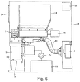
- FIG. 5 is a schematic view of a beverage dispenser comprising at least one beverage preparation assembly according to the invention.
- FIG. 6 is a front view of a beverage dispenser comprising three beverage preparation assemblies according to the invention.
- FIG. 7 is a schematic view of a beverage dispenser comprising at least one beverage preparation assembly according to the invention.
- FIGS. 8A, 8B and 8C illustrate various distributions of flows in beverage preparation assemblies
- FIGS. 9A and 9B are cross section views of a part of an assembly of the present invention illustrating the movement of the discharge port during beverage preparation.
- FIG. 1 illustrates a beverage preparation assembly 1 according to the invention.
- the assembly comprises a container 2 for storing a water soluble beverage powder.
- the container comprises a tank 21 and a powder outlet 22 .
- the container 2 usually comprises a dosing device for dosing and moving a dose of powder through the outlet 22 . This device is not represented in FIG. 1 .
- the beverage preparation assembly 1 comprises a dissolution chamber 3 positioned under the powder outlet 22 .
- This chamber 3 is configured for preparing a beverage from the water soluble beverage powder and a diluent.
- the dissolution chamber comprises two diluent inlets 31 and a beverage outlet 32 .
- the diluent inlets are connected to a diluent supply.
- the diluent is usually water.
- the chamber presents an opened top 33 through which the dose of powder dispensed from the container outlet 22 can flow.
- the illustrated chamber is deprived of any mechanical device activated by a motor for improving dissolution.
- the dissolution is obtained by the contact of the diluent with the powder.
- a chamber can configured as described in WO 2008/071613.
- the invention can also be implemented with a dissolution chamber comprising a whipper actuated by a motor (as illustrated in FIG. 7 ).
- the assembly 1 comprises an air outlet 5 configured for evacuating air from the dissolution chamber 3 .
- This air outlet 5 is positioned near to the top of the dissolution chamber.
- This air outlet is connected to a sucking device, preferably a fan, usually through a conduit.
- the conduit comprises a filter to avoid that humidity and fines enter in the sucking device.
- the assembly 1 comprises a chute 4 for guiding the water soluble beverage powder from the powder outlet 22 of the container to the dissolution chamber 3 .
- the chute is connected to the top of the dissolution chamber and this connection is airtight and watertight for example by means of a gasket 10 placed between the lateral edge of the chute and the top of the chamber.
- the chute is connected to the chamber so that the upper diluent inlet 31 and and the air outlet 5 are positioned in the annular space formed between the chute 4 and the lateral upper wall of the chamber.
- the powder outlet 22 is connected to the chute 4 by a conduit 6 .
- the powder outlet 22 , the conduit 6 , the chute 4 and the chamber are connected together through airtight connections. Said air tight connections can be obtained with the conduit 6 forming tight connections at its both extremities with the other elements of the assembly.
- the first extremity 61 of the conduit connects to the powder outlet 22 and engages said powder outlet by surrounding it.
- This first extremity of the conduit 61 is horizontally oriented so as to surround the particular illustrated powder outlet of FIG. 1 and the conduit 6 presents a bent so that its second extremity 62 is vertically oriented, yet other configuration of the conduit can be implemented depending on the orientation and shape of the powder outlet.
- the second extremity 62 of the conduit is connected to the top 41 of the chute.
- the bottom of the conduit 6 forms the chute 4 and these both elements form one single piece of material 7 . That guarantees a perfect air tight connection between these both elements.
- the conduit and the chute can be separated elements too, these elements being connected together through an airtight connection.
- the single piece of material 7 integrating the conduit 6 and the chute 4 is connected to the top of the chamber in an airtight manner with a gasket 10 as described hereabove. Said gasket enables a watertight connection also in case a whirlpool of water would reach the top of the chamber.
- the assembly 1 defines a closed environment and a closed path for the powder flowing from the powder outlet to the dissolution chamber.
- the assembly 1 comprises one air inlet 8 .
- This air inlet 8 is positioned above the chute 4 only. Due to the airtightness of the assembly around the path of the powder dose powder fines do not flow outside the dissolution chamber during dosing.
- the control of the air flow in said closed environment from the air inlet down to the chute bottom and through the air outlet enables the creation of a dry zone above the chute bottom and a wet zone under the chute bottom.
- the bottom section S 2 of the chute 4 is configured for being sufficiently large so that powder can easily flows through it without depositing on the chute.
- a unidirectional flow F of air from the air inlet 6 through the bottom section S 2 of the chute is created. It means that air flows only according to one direction through that section that is from the top down to the chamber.
- said flow is preferably homogeneously distributed through the whole bottom section S 2 of the chute.
- the unidirectional air flow flowing through the chute bottom 43 present a sufficient velocity V 2 to create a screen to prevent mist of the dissolution chamber from crossing the bottom section S 2 of the chute.
- This mist is usually composed of vapour, humid air, water droplets, water splashing and is naturally moved by convection from the chamber up to the chute.
- the velocity V 2 of the air through the chute bottom is defined to be superior to the velocity of air moving through convection.
- the air flow through the chute bottom 43 creates a barrier to humidity generated in the chamber. As a consequence the upper part of the assembly above the bottom chute 43 always remains dry, so the superior face 44 of the chute on which powder fines may fall always remain dry.
- FIG. 8A illustrates the creation of unidirectional flow F of air homogeneously distributed through the chute bottom. This flow creates a virtual frontier between an upper dry zone and a lower wet zone.
- FIG. 8B illustrates the creation of a flow of air through the chute bottom that is not homogeneously distributed; for that reason a flow of mist Fm is able to flow upwardly in the chute. This default is due to a too big section of bottom chute S 2 .
- the section S 3 of the air outlet 5 is preferably defined so that water present in the dissolution chamber cannot be sucked through the air outlet 5 .
- S 3 shall not be too small, otherwise the pressure drop would be such that droplets of liquid would be sucked during beverage preparation or cleaning.
- FIG. 8C illustrates an embodiment where a too important air flow at the air outlet 5 sucks liquid in the outlet.
- the section S 1 of the air inlet 8 is preferably defined so as to avoid pressure loss.
- S 1 shall not be too small, otherwise the flow rate of air Q would need to be significant and the control of the air flow at the section S 2 would be difficult to control.
- the air flow rate Q is controlled so as to reach the objective of maintaining a unidirectional and preferably homogeneous flow of air through the section S 2 .
- Other parameters can be optimised:
- a dose of beverage powder is dispensed from the powder outlet 22 of the container and delivered to the dissolution chamber 3 through the chute 4 , then a dose of diluent is delivered in the dissolution chamber and mixed with the dose of powder to produce a beverage, and the produced beverage is delivered through the chamber outlet 32 .
- air is sucked from the air outlet 5 so that:
- the unidirectional flow F of air prevents any flow of mist produced from flowing up through the chute 4 .
- the flow rate at which the air is sucked can be decreased during said step of dispensing a dose of beverage powder. This decrease avoids that a too important flow of air sucks powder fines through the extraction duct.
- FIG. 2 illustrates a beverage preparation assembly such as described in FIG. 1 except that the chute 4 , the conduit 6 and the air outlet 5 are part of one single piece of material 7 .
- the water and airtight connection with the powder outlet 22 and the dissolution chamber 3 is obtained with gaskets 10 .
- the assembly comprises an annular wall 42 that surrounds the bottom wall 43 of the chute. This annular wall defines two annular spaces:
- the bottoms of the both spaces 421 , 422 are opened above the dissolution chamber 3 .
- first internal annular space 421 is connected to the air outlet 5 configured for evacuating air from the dissolution chamber. So the annular wall 42 forms a conduit for sucking air from the chamber to the air outlet.
- the geometry of the first internal annular space 421 can be optimised in order to improve the control of the air flow through the system and in particular near the air outlet if necessary.
- the annular wall also prevents water from diluent inlet 31 to be partially sucked because it creates a partition wall.
- FIGS. 3A and 3B are respective side and perspective views of an example of single piece of material 7 associated to the dissolution chamber 3 as schematically illustrated in FIG. 2 .
- the air inlet 8 is protected by a grid. Such a grid can avoid that insects or small pieces fall inside when the dispenser housing is opened.
- FIGS. 4A and 4B are perspective views of each of the single piece of material 7 and the dissolution chamber 3 of FIGS. 3A and 3B .
- the single piece of material 7 comprises connecting means 7 a configured for fitting with corresponding connecting means 3 a at the top of the dissolution chamber 3 .
- the single piece of material 7 presents a slot 7 a in its internal surface in which a pin 3 a at the top of the dissolution chamber can slide.
- FIG. 4C is a perspective view of the discharge port 220 .
- the external shape of the discharge port is designed so that the extremity 61 of the single piece of material 7 can slide around the discharge port.
- the external shape of the discharge port 220 and the internal shape of the extremity 61 of the single piece of material 7 are conformal.
- the internal shape of the extremity 61 of the air outlet 5 and the external shape of the conduit to the air sucking device 9 can present conformal shapes so that they can be plugged one into another.
- the connections are also configured to enable easy dismantling for the operator.
- FIG. 5 illustrates a beverage dispenser comprising an assembly such as described hereabove.
- the diluent inlets 31 of the beverage dispenser are connected to a supply of water that is preferably a boiler 13 .
- the dispenser comprises a pump 12 to pump water from the boiler.
- the dissolution chamber 3 delivers the prepared beverage through its outlet 32 in a drinking cup that can be positioned in a dispensing area 17 .
- a powder dosing device 11 at the bottom of the powder container 2 is actuated by a motor 111 to deliver a powder dose in the dissolution chamber.
- a fan 9 is connected through an extraction duct 91 to the air outlet 5 .
- a user interface 14 enables a customer to select and launch a beverage preparation.
- a control unit 15 is linked to the user interface and the different motors to prepare the ordered beverage. All the different devices are housed in a housing 16 . The above devices are current in the field of beverage dispensers.
- FIG. 6 illustrates the front view of the beverage dispenser of FIG. 5 from which the front housing panel has been removed.
- the dispenser comprises three beverage preparation assemblies 1 a , 1 b , 1 c according to the embodiment described in FIGS. 3A and 3B .
- Each container 2 a , 2 b , 2 c can store different soluble powder like instant coffee, milk powder and chocolate powder.
- the assemblies can also differ by the volume of the mixing chambers 3 a , 3 b , 3 c that can depend on the nature of the beverage to be prepared. For example a bigger chamber may be required for preparing a milk beverage compared to a coffee.
- each beverage preparation assembly is dedicated to the preparation of a particular beverage from the powder stored in the container 2 a , 2 b , 2 c of the assembly.
- the assembly forms a powder distributing column dedicated to the preparation of the specific beverage. So no cross contamination can happen in a mixing chamber and each column can remain airtight.
- the air outlets of the beverage preparation assemblies are each connected to an extraction duct from which the fan 9 (illustrated in FIG. 5 ) sucks air.
- the diluent inlets of the chamber of each assembly are connected to the diluent supply illustrated in FIG. 5 .
- FIG. 7 illustrates an alternative beverage dispenser wherein the dissolution chamber of FIGS. 1 to 6 is replaced by a dissolution chamber comprising a whipper 35 actuated by a motor 351 .
- the other referenced elements in FIG. 7 are identical to the elements of FIG. 5 presenting the same reference.
- the fluid system for delivering water to the dissolution chamber can comprise heating and/or cooling devices and valves in order to control the temperature of water and the sequence of introduction of water in the diluent inlets according to the beverage preparation recipe.
- FIG. 9A is a magnified cross section view of the tank outlet, the discharge port 22 such as illustrated in FIG. 4C , the top of the dissolution chamber and the single piece of material 7 such as illustrated in FIGS. 3A, 3B and 4A .
- the discharge port comprises:
- an internal delivery tube 221 comprising a hollowing-out 222 in its bottom part
- an external movable cover 223 comprising a hollowing-out 224 in its bottom part.
- the internal delivery tube 221 is fixed and attached to the tank outlet.
- the external movable cover 223 surrounds the internal delivery tube 221 and is able to slide around it according to a translation movement between two positions.
- the dimensions of the both hollowing outs 222 , 224 and the relative positions of the internal delivery tube 221 and the external movable cover 223 when assembled are configured so that the external movable cover 223 covers at least a part of the internal delivery tube 221 and the hollowing-outs 222 , 224 overlap each other in one first position and cannot in the other second position. Then the dimension of the hollowing out 224 of the external movable cover is configured for overlapping at least the hollowing-out 222 of the delivery tube.
- the discharge port is represented in the second dosing position where the two hollowing outs 222 , 224 overlap each other and enable the dispensing of the soluble beverage powder which is pushed by the activation of the dosing means 11 .
- FIG. 9A illustrates too how the external movable cover 223 during powder dosing is displaced under the air inlet 8 and substantially closes the air inlet during that operation.
- the risk that powder fines escape through the air inlet is even more reduced.
- the flow rate at which air is sucked through the air outlet is decreased—or even stopped—in order to avoid that powder fines are sucked through the air outlet.
- a drawback of this sucking decrease could be that potential mist in the dissolution could flow upwardly through the chute by natural convection; yet, the closing of the air path by the end of the external movable cover 223 reduces such a chimney effect by limiting the mist velocity and its chance to flow upwardly.
- FIG. 9B corresponds to FIG. 9A except that that the external movable cover 223 is in the first rest position where the two hollowing outs 222 , 224 do not overlap each other and do not enable the dispensing of the soluble beverage powder.
- FIGS. 9A and 9B illustrates dimensions of the chute bottom section, the air inlet section and the air outlet section that enable a control of the air flow in the assembly according to the present invention.
- the illustrated assembly presents a section S 2 at the bottom chute that is circular.
- the diameter of the bottom chute is of 40 mm which is sufficiently large to limit the risk that the powder falling from the discharge port 220 deposits on the chute.
- the section S 2 is of 1257 mm 2 .
- a suction of air at a flow rate of 3,8.104 m 3 /s at the air outlet 5 a velocity V 2 of air can be reached at the bottom chute 43 that mist elevating from the dissolution chamber cannot cross.
- the height between the air inlet 8 and the chute bottom 43 is of about 100 mm.
- section S 1 of the air inlet 8 is of about 200 mm 2 preferably.
- this section S 1 corresponds to the sum of the sections of all the holes in the grid.
- section S 3 of the air outlet 5 presents a section of about 500 mm 2 preferably.
- the present invention presents the advantage of avoiding the escape of powder fines in the machine.
- the present invention presents also the advantage of controlling the movement of humidity, steam and vapour generated during the beverage preparation and preventing the presence of humidity above the powder chute.
- the present invention presents the advantage of creating separating the path of the powder from the container to the chamber in two zone: an upper dry zone and a lower humid zone.
- the assembly of the present invention forms an encapsulated path for the powder and for the flow of air inside the assembly. Due to encapsulation, powder fines do not flow outside the dissolution chamber during dosing. Moreover, due to the encapsulation, the movement of the air can be controlled: air can essentially only enter through the air inlet and essentially only flow out through the air outlet. As a consequence the control of the air flow rate by the sucking device enables a control of the movement and of the velocity of air at the different places of the assembly and in particular at the chute bottom. It becomes possible to create dry and wet zones in the assembly and to prevent humidity from flowing up from the wet zone to the dry zone. Another advantage of the present invention is that the manual cleaning interval of the chute can be optimised: it can be done less frequently and it can be done rapidly since no powder can stick in the chute.
Abstract
Description
-
- a dosing position in which the both hollowing-outs of the internal delivery tube and of the external movable cover overlap each other, and
- a rest position in which the surface of the external movable cover overlaps and closes the hollowing-out of the delivery tube.
- 1, 1 a, 1 b, 1 c beverage preparation assembly
- 2, 2 a, 2 b, 2 c container
- 21 tank
- 22 powder outlet
- 220 discharge port
- 221 internal delivery tube
- 222 hollow out
- 223 external movable cover
- 224 hollow out
- 3 dissolution chamber
- 31 diluent inlet
- 32 beverage outlet
- 33 chamber opened top
- 34 chamber top wall
- 3 a connecting means
- 35 whipper
- 351 whipper motor
- 4 chute
- 41 top of the chute
- 42 annular ring
- 421 first internal annular space
- 422 second external annular space
- 43 chute bottom
- 431 bottom wall of the chute
- 44 superior wall of the chute
- 5 air outlet
- 6 conduit
- 61 first extremity of the conduit
- 62 second extremity of the conduit
- 7 single piece of material
- 7 a connecting means
- 8 air inlet
- 9 sucking device
- 91 extraction duct
- 10 gaskets
- 11 dosing device
- 111 motor of the dosing device
- 12 pump
- 13 boiler
- 14 user interface
- 15 control unit
- 16 housing
- 17 dispensing area
Claims (11)
Priority Applications (1)
| Application Number | Priority Date | Filing Date | Title |
|---|---|---|---|
| US16/212,110 US10842312B2 (en) | 2013-12-20 | 2018-12-06 | Beverage preparation assembly |
Applications Claiming Priority (6)
| Application Number | Priority Date | Filing Date | Title |
|---|---|---|---|
| EP13198958.4 | 2013-12-20 | ||
| EP13198958 | 2013-12-20 | ||
| EP13198958 | 2013-12-20 | ||
| PCT/EP2014/077194 WO2015091143A1 (en) | 2013-12-20 | 2014-12-10 | Beverage preparation assembly |
| US201615106420A | 2016-06-20 | 2016-06-20 | |
| US16/212,110 US10842312B2 (en) | 2013-12-20 | 2018-12-06 | Beverage preparation assembly |
Related Parent Applications (2)
| Application Number | Title | Priority Date | Filing Date |
|---|---|---|---|
| US15/106,420 Division US10165891B2 (en) | 2013-12-20 | 2014-12-10 | Beverage preparation assembly |
| PCT/EP2014/077194 Division WO2015091143A1 (en) | 2013-12-20 | 2014-12-10 | Beverage preparation assembly |
Publications (2)
| Publication Number | Publication Date |
|---|---|
| US20190191917A1 US20190191917A1 (en) | 2019-06-27 |
| US10842312B2 true US10842312B2 (en) | 2020-11-24 |
Family
ID=49880534
Family Applications (2)
| Application Number | Title | Priority Date | Filing Date |
|---|---|---|---|
| US15/106,420 Active 2035-08-22 US10165891B2 (en) | 2013-12-20 | 2014-12-10 | Beverage preparation assembly |
| US16/212,110 Active 2035-07-16 US10842312B2 (en) | 2013-12-20 | 2018-12-06 | Beverage preparation assembly |
Family Applications Before (1)
| Application Number | Title | Priority Date | Filing Date |
|---|---|---|---|
| US15/106,420 Active 2035-08-22 US10165891B2 (en) | 2013-12-20 | 2014-12-10 | Beverage preparation assembly |
Country Status (11)
| Country | Link |
|---|---|
| US (2) | US10165891B2 (en) |
| EP (1) | EP3082521B1 (en) |
| JP (1) | JP6564370B2 (en) |
| CN (1) | CN105813511B (en) |
| AR (1) | AR099375A1 (en) |
| AU (1) | AU2014365189B2 (en) |
| CA (1) | CA2929276C (en) |
| MX (1) | MX2016007876A (en) |
| PH (1) | PH12016500844B1 (en) |
| RU (1) | RU2663410C1 (en) |
| WO (1) | WO2015091143A1 (en) |
Families Citing this family (10)
| Publication number | Priority date | Publication date | Assignee | Title |
|---|---|---|---|---|
| EP3210506A1 (en) * | 2016-02-29 | 2017-08-30 | Qbo Coffee GmbH | Milk frothing system and method of operation |
| CN105832211A (en) * | 2016-05-15 | 2016-08-10 | 刘昌亚 | Quantitative seasoning machine |
| IT201600083066A1 (en) * | 2016-08-05 | 2018-02-05 | Lavazza Luigi Spa | MACHINE FOR THE PREPARATION OF BEVERAGES, IN PARTICULAR ESPRESSO COFFEE AND A SELF-TRIGGERING DEVICE THAT CAN BE USED IN SUCH A MACHINE |
| DE102017101391A1 (en) * | 2017-01-25 | 2018-07-26 | Jakob Gerhardt Gmbh | Mixing device for a vending machine and vending machine with the mixing device |
| US10433671B2 (en) | 2017-03-22 | 2019-10-08 | Nicholas James Surface | Beverage dispensing machine |
| WO2019052888A1 (en) * | 2017-09-13 | 2019-03-21 | Nestec S.A. | Beverage dispenser |
| CN109820421A (en) * | 2017-11-23 | 2019-05-31 | 德隆奇电器单一股东有限责任公司 | It is used to prepare the machine and its control method of beverage |
| WO2019121499A1 (en) * | 2017-12-22 | 2019-06-27 | Societe Des Produits Nestle S.A. | Beverage dispenser with a plurality of dissolution chambers |
| DE102021101271A1 (en) * | 2021-01-21 | 2022-07-21 | Melitta Professional Coffee Solutions GmbH & Co. KG | Beverage preparation device, beverage dispenser and method for preparing a beverage |
| CN113854828B (en) * | 2021-08-23 | 2023-11-21 | 无界工场(上海)设计科技有限公司 | Drinking appliance |
Citations (6)
| Publication number | Priority date | Publication date | Assignee | Title |
|---|---|---|---|---|
| GB1004814A (en) | 1963-03-05 | 1965-09-15 | Snelwegerfabriek Olland Nv | Improvements in or relating to drink vending-machines |
| GB1006191A (en) | 1962-07-23 | 1965-09-29 | Snelwegerfabriek Olland Nv | Improvement in or relating to vending machines for beverages |
| US5918768A (en) | 1996-07-24 | 1999-07-06 | Bunn-O-Matic Corporation | Powdered beverage mixing and dispensing apparatus |
| EP2085002A1 (en) | 2008-01-30 | 2009-08-05 | Gruppo Cimbali S.p.A. | Apparatus for preparing beverages from soluble preparations with aroma-preserving device |
| US20110121017A1 (en) | 2007-08-09 | 2011-05-26 | Nestec S.A. | Single piece device for storing, metering and mixing a powder with a diluent |
| WO2013014142A1 (en) | 2011-07-28 | 2013-01-31 | Nestec S.A. | Beverage dispenser with improved refilling operation |
Family Cites Families (3)
| Publication number | Priority date | Publication date | Assignee | Title |
|---|---|---|---|---|
| JP2004097326A (en) * | 2002-09-06 | 2004-04-02 | Unimat Offisco Corp | Beverage supplier |
| CN201157760Y (en) * | 2008-03-05 | 2008-12-03 | 聂如国 | Powder-liquid mixer |
| CN101985087B (en) * | 2010-11-29 | 2012-10-17 | 西南化工研究设计院 | Unpowered powder pumping and continuous dispersive mixing method and device |
-
2014
- 2014-12-10 JP JP2016535109A patent/JP6564370B2/en active Active
- 2014-12-10 CN CN201480067790.3A patent/CN105813511B/en active Active
- 2014-12-10 AU AU2014365189A patent/AU2014365189B2/en active Active
- 2014-12-10 MX MX2016007876A patent/MX2016007876A/en active IP Right Grant
- 2014-12-10 CA CA2929276A patent/CA2929276C/en active Active
- 2014-12-10 WO PCT/EP2014/077194 patent/WO2015091143A1/en active Application Filing
- 2014-12-10 US US15/106,420 patent/US10165891B2/en active Active
- 2014-12-10 RU RU2016129582A patent/RU2663410C1/en active
- 2014-12-10 EP EP14809419.6A patent/EP3082521B1/en active Active
- 2014-12-19 AR ARP140104818A patent/AR099375A1/en unknown
-
2016
- 2016-05-06 PH PH12016500844A patent/PH12016500844B1/en unknown
-
2018
- 2018-12-06 US US16/212,110 patent/US10842312B2/en active Active
Patent Citations (6)
| Publication number | Priority date | Publication date | Assignee | Title |
|---|---|---|---|---|
| GB1006191A (en) | 1962-07-23 | 1965-09-29 | Snelwegerfabriek Olland Nv | Improvement in or relating to vending machines for beverages |
| GB1004814A (en) | 1963-03-05 | 1965-09-15 | Snelwegerfabriek Olland Nv | Improvements in or relating to drink vending-machines |
| US5918768A (en) | 1996-07-24 | 1999-07-06 | Bunn-O-Matic Corporation | Powdered beverage mixing and dispensing apparatus |
| US20110121017A1 (en) | 2007-08-09 | 2011-05-26 | Nestec S.A. | Single piece device for storing, metering and mixing a powder with a diluent |
| EP2085002A1 (en) | 2008-01-30 | 2009-08-05 | Gruppo Cimbali S.p.A. | Apparatus for preparing beverages from soluble preparations with aroma-preserving device |
| WO2013014142A1 (en) | 2011-07-28 | 2013-01-31 | Nestec S.A. | Beverage dispenser with improved refilling operation |
Also Published As
| Publication number | Publication date |
|---|---|
| CA2929276A1 (en) | 2015-06-25 |
| RU2016129582A (en) | 2018-01-25 |
| CN105813511A (en) | 2016-07-27 |
| CA2929276C (en) | 2021-12-14 |
| MX2016007876A (en) | 2016-09-07 |
| RU2663410C1 (en) | 2018-08-03 |
| EP3082521A1 (en) | 2016-10-26 |
| JP6564370B2 (en) | 2019-08-21 |
| AU2014365189B2 (en) | 2019-09-26 |
| EP3082521B1 (en) | 2017-11-01 |
| AU2014365189A1 (en) | 2016-05-12 |
| AR099375A1 (en) | 2016-07-20 |
| US10165891B2 (en) | 2019-01-01 |
| JP2017504367A (en) | 2017-02-09 |
| US20190191917A1 (en) | 2019-06-27 |
| PH12016500844A1 (en) | 2016-06-20 |
| WO2015091143A1 (en) | 2015-06-25 |
| US20170000287A1 (en) | 2017-01-05 |
| PH12016500844B1 (en) | 2016-06-20 |
| CN105813511B (en) | 2019-01-15 |
Similar Documents
| Publication | Publication Date | Title |
|---|---|---|
| US10842312B2 (en) | Beverage preparation assembly | |
| RU2462977C2 (en) | Method of making foamed liquid of soluble ingredients and solvent and device for its implementation | |
| KR102101298B1 (en) | Apparatus, systems, and methods for brewing a beverage | |
| US11564526B2 (en) | Dispenser preparing beverages from powders | |
| JP2016526419A (en) | Mixing chamber for producing beverages | |
| JP7221312B2 (en) | Beverage dispenser with powder container | |
| US20180008085A1 (en) | System for refilling beverage dispenser with powder | |
| CA2752365A1 (en) | Dispenser producing beverages from powder | |
| WO2015044147A1 (en) | Beverages dispenser using mixing chambers | |
| JP2018506346A (en) | System for refilling beverage dispensers with powder | |
| EP3342319A1 (en) | Machine preparing beverages from bulk ingredient and water | |
| WO2019052888A1 (en) | Beverage dispenser | |
| CA3232060A1 (en) | A mixing apparatus for a drink dispensing machine | |
| TW201529464A (en) | Beverages dispenser using mixing chambers |
Legal Events
| Date | Code | Title | Description |
|---|---|---|---|
| FEPP | Fee payment procedure |
Free format text: ENTITY STATUS SET TO UNDISCOUNTED (ORIGINAL EVENT CODE: BIG.); ENTITY STATUS OF PATENT OWNER: LARGE ENTITY |
|
| AS | Assignment |
Owner name: SOCIETE DES PRODUITS NESTLE S.A., SWITZERLAND Free format text: MERGER;ASSIGNOR:NESTEC S.A.;REEL/FRAME:049391/0756 Effective date: 20190528 |
|
| AS | Assignment |
Owner name: SOCIETE DES PRODUITS NESTLE S.A., SWITZERLAND Free format text: CORRECTIVE ASSIGNMENT TO CORRECT THE ENGLISH TRANSLATION TO SHOW THE FULL AND CORRECT NEW NAME IN SECTION 51. PREVIOUSLY RECORDED AT REEL: 049391 FRAME: 0756. ASSIGNOR(S) HEREBY CONFIRMS THE MERGER;ASSIGNOR:NESTEC S.A.;REEL/FRAME:049853/0398 Effective date: 20190528 |
|
| AS | Assignment |
Owner name: NESTEC S.A.,, SWITZERLAND Free format text: ASSIGNMENT OF ASSIGNORS INTEREST;ASSIGNORS:DUBIEF, FLAVIEN;SCORRANO, LUCIO;BAUDET, LARRY;AND OTHERS;SIGNING DATES FROM 20140305 TO 20140307;REEL/FRAME:049745/0957 |
|
| AS | Assignment |
Owner name: SOCIETE DES PRODUITS NESTLE S.A., SWITZERLAND Free format text: CORRECTIVE ASSIGNMENT TO CORRECT THE PATENT NUMBER 16062921 PREVIOUSLY RECORDED ON REEL 049391 FRAME 0756. ASSIGNOR(S) HEREBY CONFIRMS THE PATENT NUMBER SHOULD HAVE BEEN 16062912;ASSIGNOR:NESTEC S.A.;REEL/FRAME:054082/0001 Effective date: 20190528 Owner name: SOCIETE DES PRODUITS NESTLE S.A., SWITZERLAND Free format text: CORRECTIVE ASSIGNMENT TO CORRECT THE PATENT NUMBER 16062921 PREVIOUSLY RECORDED ON REEL 049391 FRAME 0756. ASSIGNOR(S) HEREBY CONFIRMS THE PATENT NUMBER SHOULD HAVE BEEN 16062912;ASSIGNOR:NESTEC S.A.;REEL/FRAME:054082/0165 Effective date: 20190528 |
|
| STPP | Information on status: patent application and granting procedure in general |
Free format text: NOTICE OF ALLOWANCE MAILED -- APPLICATION RECEIVED IN OFFICE OF PUBLICATIONS |
|
| STPP | Information on status: patent application and granting procedure in general |
Free format text: PUBLICATIONS -- ISSUE FEE PAYMENT VERIFIED |
|
| STCF | Information on status: patent grant |
Free format text: PATENTED CASE |