US10841680B2 - Microphone and method for processing audio signals - Google Patents
Microphone and method for processing audio signals Download PDFInfo
- Publication number
- US10841680B2 US10841680B2 US16/322,817 US201616322817A US10841680B2 US 10841680 B2 US10841680 B2 US 10841680B2 US 201616322817 A US201616322817 A US 201616322817A US 10841680 B2 US10841680 B2 US 10841680B2
- Authority
- US
- United States
- Prior art keywords
- audio signal
- gain
- amplifier
- analog
- microphone
- Prior art date
- Legal status (The legal status is an assumption and is not a legal conclusion. Google has not performed a legal analysis and makes no representation as to the accuracy of the status listed.)
- Active
Links
Images


Classifications
-
- H—ELECTRICITY
- H04—ELECTRIC COMMUNICATION TECHNIQUE
- H04R—LOUDSPEAKERS, MICROPHONES, GRAMOPHONE PICK-UPS OR LIKE ACOUSTIC ELECTROMECHANICAL TRANSDUCERS; DEAF-AID SETS; PUBLIC ADDRESS SYSTEMS
- H04R1/00—Details of transducers, loudspeakers or microphones
- H04R1/02—Casings; Cabinets ; Supports therefor; Mountings therein
- H04R1/04—Structural association of microphone with electric circuitry therefor
-
- H—ELECTRICITY
- H03—ELECTRONIC CIRCUITRY
- H03F—AMPLIFIERS
- H03F3/00—Amplifiers with only discharge tubes or only semiconductor devices as amplifying elements
- H03F3/181—Low frequency amplifiers, e.g. audio preamplifiers
- H03F3/183—Low frequency amplifiers, e.g. audio preamplifiers with semiconductor devices only
- H03F3/185—Low frequency amplifiers, e.g. audio preamplifiers with semiconductor devices only with field-effect devices
-
- H—ELECTRICITY
- H03—ELECTRONIC CIRCUITRY
- H03G—CONTROL OF AMPLIFICATION
- H03G3/00—Gain control in amplifiers or frequency changers without distortion of the input signal
- H03G3/20—Automatic control
- H03G3/30—Automatic control in amplifiers having semiconductor devices
- H03G3/3005—Automatic control in amplifiers having semiconductor devices in amplifiers suitable for low-frequencies, e.g. audio amplifiers
- H03G3/3026—Automatic control in amplifiers having semiconductor devices in amplifiers suitable for low-frequencies, e.g. audio amplifiers the gain being discontinuously variable, e.g. controlled by switching
-
- H—ELECTRICITY
- H03—ELECTRONIC CIRCUITRY
- H03G—CONTROL OF AMPLIFICATION
- H03G3/00—Gain control in amplifiers or frequency changers without distortion of the input signal
- H03G3/20—Automatic control
- H03G3/30—Automatic control in amplifiers having semiconductor devices
- H03G3/32—Automatic control in amplifiers having semiconductor devices the control being dependent upon ambient noise level or sound level
-
- H—ELECTRICITY
- H04—ELECTRIC COMMUNICATION TECHNIQUE
- H04R—LOUDSPEAKERS, MICROPHONES, GRAMOPHONE PICK-UPS OR LIKE ACOUSTIC ELECTROMECHANICAL TRANSDUCERS; DEAF-AID SETS; PUBLIC ADDRESS SYSTEMS
- H04R3/00—Circuits for transducers, loudspeakers or microphones
-
- H—ELECTRICITY
- H04—ELECTRIC COMMUNICATION TECHNIQUE
- H04R—LOUDSPEAKERS, MICROPHONES, GRAMOPHONE PICK-UPS OR LIKE ACOUSTIC ELECTROMECHANICAL TRANSDUCERS; DEAF-AID SETS; PUBLIC ADDRESS SYSTEMS
- H04R2430/00—Signal processing covered by H04R, not provided for in its groups
- H04R2430/01—Aspects of volume control, not necessarily automatic, in sound systems
Definitions
- the present disclosure relates to microphones, and more particularly, to a microphone including an amplifier with multiple gain levels and a method for processing audio signals.
- a microphone with a constant gain configuration could apply to one or several scenarios but fail to operate well in other scenarios, which results in overall performance degradation for the microphone.
- Embodiments of the present disclosure provide a microphone including: a main body, where an analog audio signal is generated in the main body representing an audio sound received by the microphone; and an amplifier disposed in the main body, where the amplifier is adapted to amplify the analog signal representation of the audio sound, and the amplifier is configured with multiple gain levels.
- the amplifier may include a non-inverting amplifier and an analog switch.
- the amplifier may include: an operational amplifier including a non-inverting input, an inverting input and an output; an analog switch, where a first end of the analog switch is coupled with the inverting input and a second end of the analog switch is coupled with the output; a first resistor, where a first end of the first resistor is coupled with the first end of the analog switch and a second end of the first resistor is coupled with the second end of the analog switch; and a second resistor, where a first end of the second resistor is coupled with the first end of the first resistor and a second end of the second resistor is grounded.
- the operational amplifier may be a Junction gate Field-Effect Transistor (JFET) input operational amplifier.
- JFET Junction gate Field-Effect Transistor
- the first resistor in order to achieve a non-unity gain of 30 dB for the amplifier, may have impedance thirty times the second resistor.
- impedance of the first resistor is 30K ohm and impedance of the second resistor is 1K ohm results in a gain of 31.
- 20*log 10 31 is 29.83 dB that is rounded to 30 dB.
- the microphone may further include: an Analog to Digital converter (A/D converter) adapted to convert the amplified audio signal from an analog signal representation to a digital signal representation to acquire a digital audio signal; and a bit shifter adapted to shift the digital signal representation by at least one bit based on the multiple gain levels.
- A/D converter Analog to Digital converter
- the digital audio signal may include more than 16 bits. In some embodiments, the digital audio signal may include 21 bits or even more depending on minimum and maximum gain and A/D converter word length.
- the bit shifter may shift the digital audio signal to the left by at least one bit to compensate for a highest gain among the multiple gain levels. For an example of two gains including a unity gain and a non-unity gain, if the unity gain is configured to amplify an analog audio signal, the bit shifter shifts a corresponding digital audio signal to the left by at least one bit corresponding to the non-unity gain.
- quantity of bits shifted may be a gain difference against the highest gain divided by 6 dB. For example, if a gain difference between two gains (such as 30 dB and 12 dB) is 18 dB, the bit shifter shifts the digital audio signal to the left by 3 bits. Thus, digital audio signals from the A/D converter are properly scaled to the highest gain.
- the microphone may further include: a controller configured to select a gain from the multiple gain levels based on a property of the analog audio signal. In some embodiments, the controller may select a gain from the multiple gain levels via comparing energy of the analog audio signal to a threshold relevant to the property of the analog audio signal. In some embodiments, the controller may further be configured to transmit either the selected gain or quantity of bits to be shifted corresponding to the gain difference to the bit shifter.
- the multiple gain levels may include a unity gain and at least one non-unity gain. In some embodiments, the at least one non-unity gain may include any gain greater than the unity gain. In some embodiments, the at least one non-unity gain may include at least one of multiples of six decibels. In some embodiments, the multiple gain levels may include 0 dB and 30 dB.
- the embodiments of the present disclosure may further include a method for processing audio signals including: acquiring an analog audio signal; selecting a gain from multiple gain levels of an amplifier based on a property of the acquired analog audio signal, where the amplifier is built in a main body of a microphone; and amplifying the acquired analog audio signal according to the selected gain.
- the gain may be selected from the multiple gain levels via comparing energy of the acquired analog audio signal to a threshold relevant to the property of the acquired analog audio signal.
- the method may further include: converting the amplified audio signal from an analog signal representation to a digital signal representation to acquire a digital audio signal; and shifting the digital audio signal by at least one bit based on the multiple gain levels.
- the digital audio signal may include more than 16 bits.
- the bit shifter may shift the digital audio signal to the left by at least one bit to properly scale the digital audio signal based on a highest gain among the multiple gain levels.
- quantity of bits shifted may be a gain difference against the highest gain divided by 6 dB.
- the multiple gain levels may include a unity gain and at least one non-unity gain.
- the at least one non-unity gain may include any gain greater than the unity gain.
- the at least one non-unity gain may include at least one of multiples of six decibels.
- a microphone including an amplifier with multiple gain levels can have flexibility in gain selection so as to improve overall performance for different scenarios. Further, a wider dynamic range can be realized without changing effective sensitivity and scaling of audio signals.
- FIG. 1 schematically illustrates a structural diagram for a microphone according to an embodiment in the present disclosure
- FIG. 2 schematically illustrates a structural diagram for the amplification system as shown in FIG. 1 according to an embodiment in the present disclosure
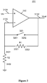
- FIG. 3 schematically illustrates an example of a structural diagram for the amplifier as shown in FIG. 2 according to an embodiment in the present disclosure
- FIG. 4 schematically illustrates a flow diagram for a method for processing audio signals according to an embodiment in the present disclosure.
- FIG. 1 schematically illustrates a structural diagram for a microphone 100 according to an embodiment in the present disclosure.
- the microphone 100 includes a main body 101 , where the main body 101 includes a backplate 103 and an amplification system 105 disposed on the backplate 103 .
- an analog audio signal is generated in the main body 101 based on an audio sound received by the microphone 100 .
- the backplate 103 may be a printed wire board.
- the amplification system 105 is adapted to amplify the analog audio signal so as to acquire an amplified audio signal.
- FIG. 2 schematically illustrates a structural diagram for the amplification system 105 as shown in FIG. 1 according to an embodiment in the present disclosure.
- the amplification system 105 at least includes an amplifier 201 and a controller 203 .
- the amplifier 201 is adapted to amplify the analog audio signal, and the amplifier 201 is configured with multiple gain levels.
- the multiple gain levels may include a unity gain (namely, a gain with zero decibel (dB)) and at least one non-unity gain.
- the at least one non-unity gain may include any gain greater than 0 dB.
- the at least one non-unity gain may include multiples of 6 dB.
- the at least one non-unity gain may include a single gain, such as 30 dB, where 30 dB is typically used for a microphone to listen to a speaker who is several meters away from the microphone.
- the at least one non-unity gain may include multiple gains, such as 18 dB, 30 dB and 42 dB, where 30 dB is used for a microphone to listen to a first sound source such as a talker, that is several meters away from the microphone, 18 dB is used when the microphone is listening to a second sound source that is closer and/or louder than the first sound source, but still several meters away from the microphone, and 42 dB is used for the microphone to listen to a third sound source that is farther and/or weaker than the first sound source or even more distant or weaker sounds.
- a first sound source such as a talker
- 18 dB is used when the microphone is listening to a second sound source that is closer and/or louder than the first sound source, but still several meters away from the microphone
- 42 dB is used for the microphone to listen to a third sound source that is farther and/or weaker than the first sound source or even more distant or weaker sounds.
- the amplifier 201 may include a non-inverting amplifier including multiple impedances and multiple analog switches.
- FIG. 3 schematically illustrates an example of a structural diagram for the amplifier 201 as shown in FIG. 2 according to an embodiment in the present disclosure.
- the amplifier 201 includes an operational amplifier 310 , an analog switch 320 , a first resistor R 1 and a second resistor R 2 .
- the operational amplifier 310 has a non-inverting input 3101 , an inverting input 3103 and an output 3102 , where an input voltage Vin is applied to the non-inverting input 3101 and an output voltage Vout is obtained at the output 3102 .
- the amplifier 201 is a non-inverting amplifier.
- the operational amplifier 310 may be a JFET input operational amplifier, thus in this case, the amplifier 201 is a JFET input non-inverting amplifier.
- a first end 3201 of the analog switch 320 is coupled with the inverting input 3103 and a second end 3202 of the analog switch 320 is coupled with the output 3102 .
- a first end 3301 of the first resistor R 1 is coupled with the first end 3201 and a second end 3302 of the first resistor R 1 is coupled with the second end 3202 .
- a first end 3401 of the second resistor R 2 is coupled with the first end 3301 and a second end 3402 of the second resistor R 2 is grounded.
- the amplifier 201 serves as a unity amplifier with a gain of 0 dB. Otherwise, the amplifier 201 serves as a non-inverting amplifier with a gain determined according to the first resistor R 1 and the second resistor R 2 . Specifically, the gain in decibels is acquired by calculating the following expression: 20*Log 10 (1+ R 1/ R 2) (1) For an example, a resistance of the first resistor R 1 is thirty times that of the second resistor R 2 , thus the gain is about 30 dB according to the expression (1).
- the amplifier 201 may include other types of amplifiers, such as an inverting amplifier.
- the controller 203 is configured to select a gain from the multiple gain levels based on a property, such as a total short term average level or a sample by sample level or a property of the analog audio signal.
- the property of the analog audio signal may be energy, a peak to average energy crest factor, remaining headroom margin, etc.
- the controller 203 is configured to select a gain from the multiple gain levels via comparing energy of the analog audio signal to a threshold relevant to the property of the analog audio signal. For example, human speech generally has a crest factor of 12 dB.
- the controller may be further configured to delay switching of the gain to occur during or after a zero-crossing of the analog audio signal so as to minimize any click in the audio sound that the gain change may produce with an larger instantaneous audio signal level when the analog audio signal is large.
- a non-unity gain setting of the microphone amplifier is selected for the distant sound.
- the microphone is close to a source of loud sound, such as a loudspeaker, or other source of loud sound, or the microphone and sound source are both included inside a device or a system
- the unity gain is selected by the controller and assigned to the amplifier, and an echo cancellation process could be performed on an audio signal with unity gain, where the echo cancellation process requires a stationary signal path between the sound source and microphone.
- the amplification system 105 may further include an analog to digital converter (A/D converter) 205 and a bit shifter 207 .
- A/D converter analog to digital converter
- the analog to digital converter 205 is adapted to convert the amplified audio signal from an analog signal representation to a digital signal representation to acquire a digital audio signal.
- a 16-bit A/D converter is used, thus the digital audio signal includes 16 bits.
- the digital audio signal may include more than 16 bits, such as 21 bits.
- a Codec may be used instead of the A/D converter 205 to convert the amplified audio signal from an analog signal representation to a digital signal representation.
- each bit in a digital audio signal represents 6 dB of a dynamic range between the AOP and a quantization noise floor. Therefore, for a 16-bit system, a dynamic range of 96 dB is obtained, and for a 21-bit system, a dynamic range of 126 dB is obtained. For a digital audio signal, a wider dynamic range is better.
- the bit shifter 207 is adapted to bit shift the digital audio signal based on the multiple gain levels.
- the at least one non-unity gain may include at least one of multiples of 6 dB so that a simple shifting of bits could be applied instead of a more complicated scaling method involving multiplication hardware.
- the bit shifter 207 may shift the digital audio signal to the left by at least one bit to compensate for a highest gain among the multiple gain levels.
- quantity of bits shifted may be a gain difference against the highest gain divided by 6 dB, since each bit in a digital audio signal represents 6 dB.
- the digital audio signal with 0 dB is shifted to the left by 5 bits to scale the digital audio signal with 0 dB in an absolute sense to be equivalent to a digital audio signal with 30 dB gain.
- a digital audio signal with 18 dB is shifted to the left by 2 bits to achieve the same scaling as an unshifted digital audio signal with 30 dB gain
- a digital audio signal with 0 dB is shifted to the left by 5 bits to achieve the same scaling as the unshifted digital audio signal with 30 dB gain.
- digital audio signals after performing the bit shift, digital audio signals have a consistent linear value as expected since digital audio signals with different gains are modified through the bit shift so as to achieve the consistent linear values, thus absolute scaling of the digital audio signals is consistent.
- the digital audio signals may be properly scaled in an absolute sense as a 21 bit digital word for further signal processing.
- the bit shifter 207 may acquire gains from the controller 203 . In some embodiments, the bit shifter 207 may acquire gains based on the digital audio signal from the A/D converter 205 . Specifically, a digital audio signal with a greater value may require a lower gain against a digital audio signal with a smaller value to get even with the highest gain. In some embodiments, the bit shifter 207 may acquire quantity of bits to be shifted according to a gain acquired from the controller 203 . In some embodiments, the bit shifter 207 may acquire quantity of bits to be shifted from the controller 203 . In these cases, the acquired gains are modified by the bit shifter 207 to become consistent with the highest gain.
- a downstream processing is not required to be aware of the gain used by the amplifier 201 for a particular audio signal, so that digital audio signals after performing the bit shift appear stationary to the downstream processing.
- the digital audio signals after performing the bit shift have a consistent gain so that the echo cancellation process is performed on the digital audio signals without knowing the specific instantaneous gain used by the amplifier 201 .
- FIG. 4 schematically illustrates a flow diagram for a method for processing audio signals 400 according to an embodiment in the present disclosure.
- step 401 an analog audio signal is acquired.
- a gain is selected from multiple gain levels of an amplifier based on a property of the acquired analog audio signal.
- the amplifier may be disposed on a backplate included in a main body of a microphone, and the property may be energy, a peak to average energy crest factor, remaining headroom margin, etc. as previously described.
- the gain may be selected from the multiple gain levels via comparing energy of the acquired analog audio signal to a threshold relevant to the property of the acquired analog audio signal, such as an acoustic overload point (AOP).
- AOP acoustic overload point
- the multiple gain levels may include a unity gain of 0 dB and at least one non-unity gain. In some embodiments, the at least one non-unity gain may include any gain greater than 0 dB. In some embodiments, the at least one non-unity gain may include at least one of multiples of 6 dB. In some embodiments, the multiple gain levels may include 0 dB and 30 dB. In some embodiments, the multiple gain levels may include 0 dB, 18 dB, 30 dB and 42 dB.
- the acquired analog audio signal is amplified according to the selected gain.
- an amplifier of a microphone amplifies a distant sound according to a non-unity gain. And, the unity gain is selected and assigned to the amplifier when cancelling a much louder echo generated due to a short and direct path from the source of loudspeaker sound close to the microphone or inside a device or system including the microphone.
- the amplified audio signal is converted from an analog signal representation to a digital signal representation to acquire a digital audio signal.
- the digital audio signal includes more than 16 bits.
- the digital audio signal includes 21 bits corresponding to a dynamic range of 126 dB.
- the digital audio signal is shifted by at least one bit based on the multiple gain levels.
- the at least one non-unity gain may include at least one of multiples of 6 dB so that a simple shifting of bits could be applied instead of a more complicated scaling method involving multiplication hardware.
- the digital audio signal may be shifted to the left by at least one bit to compensate for the highest gain among the multiple gain levels.
- quantity of bits shifted may be a gain difference against the highest and lowest gain divided by 6 dB. Accordingly, digital audio signals after performing the bit shift have a consistent gain and appear stationary to a downstream processing such as an echo cancellation process.
Abstract
Description
20*Log10(1+R1/R2) (1)
For an example, a resistance of the first resistor R1 is thirty times that of the second resistor R2, thus the gain is about 30 dB according to the expression (1).
Claims (17)
Applications Claiming Priority (1)
| Application Number | Priority Date | Filing Date | Title |
|---|---|---|---|
| PCT/CN2016/094217 WO2018027583A1 (en) | 2016-08-09 | 2016-08-09 | Microphone and method for processing audio signals |
Publications (2)
| Publication Number | Publication Date |
|---|---|
| US20190182574A1 US20190182574A1 (en) | 2019-06-13 |
| US10841680B2 true US10841680B2 (en) | 2020-11-17 |
Family
ID=61161370
Family Applications (1)
| Application Number | Title | Priority Date | Filing Date |
|---|---|---|---|
| US16/322,817 Active US10841680B2 (en) | 2016-08-09 | 2016-08-09 | Microphone and method for processing audio signals |
Country Status (4)
| Country | Link |
|---|---|
| US (1) | US10841680B2 (en) |
| EP (1) | EP3497943A4 (en) |
| CN (1) | CN109565630A (en) |
| WO (1) | WO2018027583A1 (en) |
Families Citing this family (2)
| Publication number | Priority date | Publication date | Assignee | Title |
|---|---|---|---|---|
| CN110213695A (en) * | 2019-05-31 | 2019-09-06 | 广州市锐丰智能科技有限公司 | Improve the method and intelligent sound reinforcement system of the output audio signal-to-noise ratio of sound reinforcement system |
| CN113709626A (en) * | 2021-08-04 | 2021-11-26 | Oppo广东移动通信有限公司 | Audio recording method, device, storage medium and computer equipment |
Citations (14)
| Publication number | Priority date | Publication date | Assignee | Title |
|---|---|---|---|---|
| JPH06217399A (en) | 1992-12-28 | 1994-08-05 | Junzo Ono | Hearing aid provided with function correcting automatically strength of sound |
| US20070274552A1 (en) * | 2006-05-23 | 2007-11-29 | Alon Konchitsky | Environmental noise reduction and cancellation for a communication device including for a wireless and cellular telephone |
| CN101325819A (en) | 2007-06-13 | 2008-12-17 | 雅马哈株式会社 | Electroacoustic transformator |
| US20090003629A1 (en) | 2005-07-19 | 2009-01-01 | Audioasics A/A | Programmable Microphone |
| CN101400009A (en) | 2007-09-27 | 2009-04-01 | 美商富迪科技股份有限公司 | Microphone circuit |
| US20090096528A1 (en) | 2007-03-19 | 2009-04-16 | Panasonic Corporation | Agc circuit |
| US20090285414A1 (en) * | 2008-05-15 | 2009-11-19 | Fortemedia, Inc. | Audio processing method and system |
| US20100246877A1 (en) * | 2009-01-20 | 2010-09-30 | Fortemedia, Inc. | Miniature MEMS Condenser Microphone Package and Fabrication Method Thereof |
| US20110150237A1 (en) | 2009-12-21 | 2011-06-23 | Oki Semiconductor Co., Ltd. | Signal processing device and signal processing method |
| US8265304B2 (en) * | 2009-12-09 | 2012-09-11 | Osborne Gary T | Microphone suitable for professional live performance |
| US8324969B2 (en) | 2011-03-11 | 2012-12-04 | Dialog Semiconductor Gmbh | Delta-sigma modulator approach to increased amplifier gain resolution |
| US20130044898A1 (en) * | 2011-08-18 | 2013-02-21 | Jordan T. Schultz | Sensitivity Adjustment Apparatus And Method For MEMS Devices |
| CN103378813A (en) | 2012-04-16 | 2013-10-30 | 英飞凌科技股份有限公司 | System and method for high input capacitive signal amplifier |
| CN104469608A (en) | 2013-09-25 | 2015-03-25 | 罗伯特·博世有限公司 | System and method for adjusting microphone functionality |
Family Cites Families (4)
| Publication number | Priority date | Publication date | Assignee | Title |
|---|---|---|---|---|
| EP2453574A1 (en) * | 2010-11-15 | 2012-05-16 | ST-Ericsson SA | Interface circuit for connecting a microphone circuit to a preamplifier |
| US20140112483A1 (en) * | 2012-10-24 | 2014-04-24 | Alcatel-Lucent Usa Inc. | Distance-based automatic gain control and proximity-effect compensation |
| CN104113382B (en) * | 2013-04-22 | 2016-08-03 | 瑞昱半导体股份有限公司 | Wireless transmitting system and determine the method for preset gain of wireless transmitting system |
| JP2015070278A (en) * | 2013-09-26 | 2015-04-13 | 三菱電機株式会社 | Acoustic parameter adjustment device |
-
2016
- 2016-08-09 CN CN201680088275.2A patent/CN109565630A/en active Pending
- 2016-08-09 EP EP16912038.3A patent/EP3497943A4/en not_active Withdrawn
- 2016-08-09 US US16/322,817 patent/US10841680B2/en active Active
- 2016-08-09 WO PCT/CN2016/094217 patent/WO2018027583A1/en unknown
Patent Citations (19)
| Publication number | Priority date | Publication date | Assignee | Title |
|---|---|---|---|---|
| JPH06217399A (en) | 1992-12-28 | 1994-08-05 | Junzo Ono | Hearing aid provided with function correcting automatically strength of sound |
| US20090003629A1 (en) | 2005-07-19 | 2009-01-01 | Audioasics A/A | Programmable Microphone |
| US20070274552A1 (en) * | 2006-05-23 | 2007-11-29 | Alon Konchitsky | Environmental noise reduction and cancellation for a communication device including for a wireless and cellular telephone |
| US20090096528A1 (en) | 2007-03-19 | 2009-04-16 | Panasonic Corporation | Agc circuit |
| CN101325819A (en) | 2007-06-13 | 2008-12-17 | 雅马哈株式会社 | Electroacoustic transformator |
| US20090052696A1 (en) | 2007-06-13 | 2009-02-26 | Yamaha Corporation | Electroacoustic transducer |
| CN101400009A (en) | 2007-09-27 | 2009-04-01 | 美商富迪科技股份有限公司 | Microphone circuit |
| US20090086992A1 (en) | 2007-09-27 | 2009-04-02 | Fortemedia, Inc. | Microphone circuit and charge amplifier thereof |
| US20090285414A1 (en) * | 2008-05-15 | 2009-11-19 | Fortemedia, Inc. | Audio processing method and system |
| US20100246877A1 (en) * | 2009-01-20 | 2010-09-30 | Fortemedia, Inc. | Miniature MEMS Condenser Microphone Package and Fabrication Method Thereof |
| US8265304B2 (en) * | 2009-12-09 | 2012-09-11 | Osborne Gary T | Microphone suitable for professional live performance |
| US20110150237A1 (en) | 2009-12-21 | 2011-06-23 | Oki Semiconductor Co., Ltd. | Signal processing device and signal processing method |
| US8324969B2 (en) | 2011-03-11 | 2012-12-04 | Dialog Semiconductor Gmbh | Delta-sigma modulator approach to increased amplifier gain resolution |
| US20130044898A1 (en) * | 2011-08-18 | 2013-02-21 | Jordan T. Schultz | Sensitivity Adjustment Apparatus And Method For MEMS Devices |
| CN103858446A (en) | 2011-08-18 | 2014-06-11 | 美商楼氏电子有限公司 | Sensitivity adjustment apparatus and method for MEMS devices |
| CN103378813A (en) | 2012-04-16 | 2013-10-30 | 英飞凌科技股份有限公司 | System and method for high input capacitive signal amplifier |
| US9413317B2 (en) | 2012-04-16 | 2016-08-09 | Infineon Technologies Ag | System and method for high input capacitive signal amplifier |
| CN104469608A (en) | 2013-09-25 | 2015-03-25 | 罗伯特·博世有限公司 | System and method for adjusting microphone functionality |
| US20150086043A1 (en) | 2013-09-25 | 2015-03-26 | Robert Bosch Gmbh | System and method for adjusting microphone functionality |
Non-Patent Citations (2)
| Title |
|---|
| European Search Report for Application No. 16912038.3, dated Jan. 31, 2020, 7 pages. |
| International Search Report dated May 12, 2017, PCT/CN2016/094217 filed Aug. 9, 2016, 12 pgs. |
Also Published As
| Publication number | Publication date |
|---|---|
| WO2018027583A1 (en) | 2018-02-15 |
| EP3497943A1 (en) | 2019-06-19 |
| EP3497943A4 (en) | 2020-03-04 |
| US20190182574A1 (en) | 2019-06-13 |
| CN109565630A (en) | 2019-04-02 |
Similar Documents
| Publication | Publication Date | Title |
|---|---|---|
| RU2520420C2 (en) | Method and system for scaling suppression of weak signal with stronger signal in speech-related channels of multichannel audio signal | |
| US10015591B2 (en) | Pickup apparatus and pickup method | |
| US9071214B2 (en) | Audio signal controller | |
| US9083288B2 (en) | High level capable audio amplification circuit | |
| JP4249729B2 (en) | Automatic gain control method, automatic gain control device, automatic gain control program, and recording medium recording the same | |
| WO2012090282A1 (en) | Voice control device, method of controlling voice, voice control program and mobile terminal device | |
| EP3275208B1 (en) | Sub-band mixing of multiple microphones | |
| CN101140760A (en) | Sound signal collecting and processing system and method thereof | |
| JP2008306630A (en) | Sound volume control apparatus and method | |
| US10841680B2 (en) | Microphone and method for processing audio signals | |
| CN111345047A (en) | Audio signal processing method, apparatus and storage medium | |
| MX2022001162A (en) | Acoustic echo cancellation control for distributed audio devices. | |
| TWI657435B (en) | Apparatus and method of audio processing | |
| JP2022506570A (en) | How to improve the sound quality of the super directional ultrasonic speaker device, and the ultrasonic speaker device equipped with it. | |
| US11894006B2 (en) | Compressor target curve to avoid boosting noise | |
| US10242691B2 (en) | Method of enhancing speech using variable power budget | |
| EP3611936B1 (en) | Noise elimination device, noise elimination method and noise elimination program | |
| US20200105243A1 (en) | Audio processing system | |
| US10887711B2 (en) | Sound recording circuit | |
| US9515619B2 (en) | Amplifier arrangement with limiting module | |
| Tzur et al. | Sound equalization in a noisy environment | |
| JPH02209027A (en) | Acoustic echo canceller | |
| Ngo et al. | An integrated approach for noise reduction and dynamic range compression in hearing aids | |
| JP2010041280A (en) | Signal processing apparatus | |
| US10142756B2 (en) | Signal processing device and signal processing method |
Legal Events
| Date | Code | Title | Description |
|---|---|---|---|
| AS | Assignment |
Owner name: HARMAN INTERNATIONAL INDUSTRIES, INCORPORATED, CON Free format text: ASSIGNMENT OF ASSIGNORS INTEREST;ASSIGNORS:MICHEL, ALAN;GAO, SEAN;LV, GUANGYUE;SIGNING DATES FROM 20190125 TO 20190129;REEL/FRAME:048222/0291 Owner name: HARMAN INTERNATIONAL INDUSTRIES, INCORPORATED, CONNECTICUT Free format text: ASSIGNMENT OF ASSIGNORS INTEREST;ASSIGNORS:MICHEL, ALAN;GAO, SEAN;LV, GUANGYUE;SIGNING DATES FROM 20190125 TO 20190129;REEL/FRAME:048222/0291 |
|
| FEPP | Fee payment procedure |
Free format text: ENTITY STATUS SET TO UNDISCOUNTED (ORIGINAL EVENT CODE: BIG.); ENTITY STATUS OF PATENT OWNER: LARGE ENTITY |
|
| STPP | Information on status: patent application and granting procedure in general |
Free format text: DOCKETED NEW CASE - READY FOR EXAMINATION |
|
| STPP | Information on status: patent application and granting procedure in general |
Free format text: NON FINAL ACTION MAILED |
|
| STPP | Information on status: patent application and granting procedure in general |
Free format text: NOTICE OF ALLOWANCE MAILED -- APPLICATION RECEIVED IN OFFICE OF PUBLICATIONS |
|
| STPP | Information on status: patent application and granting procedure in general |
Free format text: AWAITING TC RESP., ISSUE FEE NOT PAID |
|
| STPP | Information on status: patent application and granting procedure in general |
Free format text: RESPONSE TO NON-FINAL OFFICE ACTION ENTERED AND FORWARDED TO EXAMINER |
|
| STPP | Information on status: patent application and granting procedure in general |
Free format text: NON FINAL ACTION MAILED |
|
| STPP | Information on status: patent application and granting procedure in general |
Free format text: RESPONSE TO NON-FINAL OFFICE ACTION ENTERED AND FORWARDED TO EXAMINER |
|
| STPP | Information on status: patent application and granting procedure in general |
Free format text: PUBLICATIONS -- ISSUE FEE PAYMENT VERIFIED |
|
| STCF | Information on status: patent grant |
Free format text: PATENTED CASE |