US10839819B2 - Block-based audio encoding/decoding device and method therefor - Google Patents
Block-based audio encoding/decoding device and method therefor Download PDFInfo
- Publication number
- US10839819B2 US10839819B2 US16/081,169 US201716081169A US10839819B2 US 10839819 B2 US10839819 B2 US 10839819B2 US 201716081169 A US201716081169 A US 201716081169A US 10839819 B2 US10839819 B2 US 10839819B2
- Authority
- US
- United States
- Prior art keywords
- block
- frame
- input signal
- encoding
- signal
- Prior art date
- Legal status (The legal status is an assumption and is not a legal conclusion. Google has not performed a legal analysis and makes no representation as to the accuracy of the status listed.)
- Active, expires
Links
- 238000000034 method Methods 0.000 title claims abstract description 126
- 230000005236 sound signal Effects 0.000 claims abstract description 100
- 230000001131 transforming effect Effects 0.000 claims abstract description 18
- 238000013139 quantization Methods 0.000 claims description 20
- 238000005516 engineering process Methods 0.000 description 16
- 238000007906 compression Methods 0.000 description 8
- 230000006835 compression Effects 0.000 description 6
- 239000000203 mixture Substances 0.000 description 6
- 230000002708 enhancing effect Effects 0.000 description 4
- 238000009432 framing Methods 0.000 description 4
- 230000012447 hatching Effects 0.000 description 4
- 238000010586 diagram Methods 0.000 description 2
- 230000004075 alteration Effects 0.000 description 1
- 238000006243 chemical reaction Methods 0.000 description 1
- 238000011161 development Methods 0.000 description 1
- 230000018109 developmental process Effects 0.000 description 1
- 230000000694 effects Effects 0.000 description 1
- 238000012986 modification Methods 0.000 description 1
- 230000004048 modification Effects 0.000 description 1
- 230000003287 optical effect Effects 0.000 description 1
- 238000012545 processing Methods 0.000 description 1
- 230000010076 replication Effects 0.000 description 1
- 230000003595 spectral effect Effects 0.000 description 1
- 238000012546 transfer Methods 0.000 description 1
Images


Classifications
-
- G—PHYSICS
- G10—MUSICAL INSTRUMENTS; ACOUSTICS
- G10L—SPEECH ANALYSIS TECHNIQUES OR SPEECH SYNTHESIS; SPEECH RECOGNITION; SPEECH OR VOICE PROCESSING TECHNIQUES; SPEECH OR AUDIO CODING OR DECODING
- G10L19/00—Speech or audio signals analysis-synthesis techniques for redundancy reduction, e.g. in vocoders; Coding or decoding of speech or audio signals, using source filter models or psychoacoustic analysis
- G10L19/02—Speech or audio signals analysis-synthesis techniques for redundancy reduction, e.g. in vocoders; Coding or decoding of speech or audio signals, using source filter models or psychoacoustic analysis using spectral analysis, e.g. transform vocoders or subband vocoders
- G10L19/022—Blocking, i.e. grouping of samples in time; Choice of analysis windows; Overlap factoring
-
- G—PHYSICS
- G10—MUSICAL INSTRUMENTS; ACOUSTICS
- G10L—SPEECH ANALYSIS TECHNIQUES OR SPEECH SYNTHESIS; SPEECH RECOGNITION; SPEECH OR VOICE PROCESSING TECHNIQUES; SPEECH OR AUDIO CODING OR DECODING
- G10L19/00—Speech or audio signals analysis-synthesis techniques for redundancy reduction, e.g. in vocoders; Coding or decoding of speech or audio signals, using source filter models or psychoacoustic analysis
- G10L19/02—Speech or audio signals analysis-synthesis techniques for redundancy reduction, e.g. in vocoders; Coding or decoding of speech or audio signals, using source filter models or psychoacoustic analysis using spectral analysis, e.g. transform vocoders or subband vocoders
- G10L19/032—Quantisation or dequantisation of spectral components
-
- G—PHYSICS
- G10—MUSICAL INSTRUMENTS; ACOUSTICS
- G10L—SPEECH ANALYSIS TECHNIQUES OR SPEECH SYNTHESIS; SPEECH RECOGNITION; SPEECH OR VOICE PROCESSING TECHNIQUES; SPEECH OR AUDIO CODING OR DECODING
- G10L19/00—Speech or audio signals analysis-synthesis techniques for redundancy reduction, e.g. in vocoders; Coding or decoding of speech or audio signals, using source filter models or psychoacoustic analysis
- G10L19/04—Speech or audio signals analysis-synthesis techniques for redundancy reduction, e.g. in vocoders; Coding or decoding of speech or audio signals, using source filter models or psychoacoustic analysis using predictive techniques
-
- H—ELECTRICITY
- H04—ELECTRIC COMMUNICATION TECHNIQUE
- H04N—PICTORIAL COMMUNICATION, e.g. TELEVISION
- H04N19/00—Methods or arrangements for coding, decoding, compressing or decompressing digital video signals
- H04N19/10—Methods or arrangements for coding, decoding, compressing or decompressing digital video signals using adaptive coding
- H04N19/102—Methods or arrangements for coding, decoding, compressing or decompressing digital video signals using adaptive coding characterised by the element, parameter or selection affected or controlled by the adaptive coding
- H04N19/103—Selection of coding mode or of prediction mode
- H04N19/11—Selection of coding mode or of prediction mode among a plurality of spatial predictive coding modes
-
- H—ELECTRICITY
- H04—ELECTRIC COMMUNICATION TECHNIQUE
- H04N—PICTORIAL COMMUNICATION, e.g. TELEVISION
- H04N19/00—Methods or arrangements for coding, decoding, compressing or decompressing digital video signals
- H04N19/10—Methods or arrangements for coding, decoding, compressing or decompressing digital video signals using adaptive coding
- H04N19/169—Methods or arrangements for coding, decoding, compressing or decompressing digital video signals using adaptive coding characterised by the coding unit, i.e. the structural portion or semantic portion of the video signal being the object or the subject of the adaptive coding
- H04N19/17—Methods or arrangements for coding, decoding, compressing or decompressing digital video signals using adaptive coding characterised by the coding unit, i.e. the structural portion or semantic portion of the video signal being the object or the subject of the adaptive coding the unit being an image region, e.g. an object
- H04N19/176—Methods or arrangements for coding, decoding, compressing or decompressing digital video signals using adaptive coding characterised by the coding unit, i.e. the structural portion or semantic portion of the video signal being the object or the subject of the adaptive coding the unit being an image region, e.g. an object the region being a block, e.g. a macroblock
-
- G—PHYSICS
- G10—MUSICAL INSTRUMENTS; ACOUSTICS
- G10L—SPEECH ANALYSIS TECHNIQUES OR SPEECH SYNTHESIS; SPEECH RECOGNITION; SPEECH OR VOICE PROCESSING TECHNIQUES; SPEECH OR AUDIO CODING OR DECODING
- G10L19/00—Speech or audio signals analysis-synthesis techniques for redundancy reduction, e.g. in vocoders; Coding or decoding of speech or audio signals, using source filter models or psychoacoustic analysis
- G10L19/02—Speech or audio signals analysis-synthesis techniques for redundancy reduction, e.g. in vocoders; Coding or decoding of speech or audio signals, using source filter models or psychoacoustic analysis using spectral analysis, e.g. transform vocoders or subband vocoders
- G10L19/0204—Speech or audio signals analysis-synthesis techniques for redundancy reduction, e.g. in vocoders; Coding or decoding of speech or audio signals, using source filter models or psychoacoustic analysis using spectral analysis, e.g. transform vocoders or subband vocoders using subband decomposition
-
- G—PHYSICS
- G10—MUSICAL INSTRUMENTS; ACOUSTICS
- G10L—SPEECH ANALYSIS TECHNIQUES OR SPEECH SYNTHESIS; SPEECH RECOGNITION; SPEECH OR VOICE PROCESSING TECHNIQUES; SPEECH OR AUDIO CODING OR DECODING
- G10L19/00—Speech or audio signals analysis-synthesis techniques for redundancy reduction, e.g. in vocoders; Coding or decoding of speech or audio signals, using source filter models or psychoacoustic analysis
- G10L19/02—Speech or audio signals analysis-synthesis techniques for redundancy reduction, e.g. in vocoders; Coding or decoding of speech or audio signals, using source filter models or psychoacoustic analysis using spectral analysis, e.g. transform vocoders or subband vocoders
- G10L19/0212—Speech or audio signals analysis-synthesis techniques for redundancy reduction, e.g. in vocoders; Coding or decoding of speech or audio signals, using source filter models or psychoacoustic analysis using spectral analysis, e.g. transform vocoders or subband vocoders using orthogonal transformation
-
- G—PHYSICS
- G10—MUSICAL INSTRUMENTS; ACOUSTICS
- G10L—SPEECH ANALYSIS TECHNIQUES OR SPEECH SYNTHESIS; SPEECH RECOGNITION; SPEECH OR VOICE PROCESSING TECHNIQUES; SPEECH OR AUDIO CODING OR DECODING
- G10L19/00—Speech or audio signals analysis-synthesis techniques for redundancy reduction, e.g. in vocoders; Coding or decoding of speech or audio signals, using source filter models or psychoacoustic analysis
- G10L19/02—Speech or audio signals analysis-synthesis techniques for redundancy reduction, e.g. in vocoders; Coding or decoding of speech or audio signals, using source filter models or psychoacoustic analysis using spectral analysis, e.g. transform vocoders or subband vocoders
- G10L19/03—Spectral prediction for preventing pre-echo; Temporary noise shaping [TNS], e.g. in MPEG2 or MPEG4
Definitions
- At least one example embodiment relates to an apparatus and method for encoding/decoding an audio signal.
- Technology for encoding/decoding an audio signal refers to technology for compressing an audio signal and transmitting the compressed audio signal.
- the great technical developments have been achieved over the past decades.
- MPEG audio encoding/decoding technology that is, MPEG-1 layer III (MP3) technology refers to a scheme of designing a quantizer and compressing data based on a psychoacoustic model of a human being to minimize a loss of a perceptual sound quality.
- MP3 MPEG-1 layer III
- MPEG-2 advanced audio coding (AAC) technology refers to a scheme of enhancing a compression performance by applying a psychoacoustic model to a full band audio frequency coefficient based on modified discrete cosine transform (MDCT).
- MDCT modified discrete cosine transform
- 3rd generation (3G) MPEG audio encoding/decoding technology that is, MPEG-4 parametric coding technology refers to a scheme of enhancing a compression rate from a low bitrate of 48 kbps or less using parametric coding technology.
- the parametric encoding/decoding technology includes parametric stereo (PS) technology for encoding/decoding a stereo channel and spectral band replication (SBR) technology for encoding/decoding a high band signal.
- PS parametric stereo
- SBR spectral band replication
- 4th generation (4G) MPEG audio encoding/decoding technology that is, unified speech and audio coding (USAC) technology refers to USAC audio codec technology for enhancing the sound quality of low bitrate voice, and has a compression performance similar to AAC 128 kbps to provide a CD-class high quality.
- USAC unified speech and audio coding
- the audio encoding/decoding technologies according to the related art may be understood to enhance the compression performance using the psychoacoustic model, however, to reach the limit of performance due to a quantization based on a one-dimensional (1D) psychoacoustic model.
- At least one example embodiment provides an apparatus and method that may enhance an encoding rate by reconfiguring and encoding an input audio signal as a two-dimensional (2D) signal.
- At least one example embodiment provides an apparatus and method that may flexibly perform homogeneity and synchronization of an encoding scheme since the same framing structure as a video signal may be achieved using an encoding scheme that is interpreted based on a block unit.
- a method of encoding an audio signal including dividing each of frame of input signal that constitute an audio signal into a plurality of subframes; transforming the subframes to a frequency domain; determining a two-dimensional (2D) intra block using the subframes transformed to the frequency domain; and encoding the 2D intra block.
- the 2D intra block is a block that two-dimensionally displays frequency coefficients of the subframes transformed to the frequency domain using a time and a frequency.
- the transforming of the subframes to the frequency domain may include grouping the subframes based on an overlap-add; applying a window to the grouped subframes; and transforming the subframes to which the window is applied to the frequency domain.
- the grouping may include grouping a last subframe divided from a current frame and a first subframe divided from a subsequent frame among the frame of input signal.
- the encoding may include dividing each of the subframes of the 2D intra block into a plurality of subband signals; predicting a correlation between the subband signals; quantizing a high band signal of which a bandwidth value is greater than a reference value among the subband signals, using a scale factor; quantizing a prediction result of a low band signal of which a bandwidth value is less than or equal to the reference value among the subband signals and a residual signal between the subband signals; and converting a quantization index, the scale factor, the quantized high band signal, the residual signal, and the prediction result to a bitstream.
- a method of decoding an audio signal including decoding a two-dimensional (2D) intra block from a received bitstream; determining subframes of a frequency domain using the 2D intra block; transforming the subframes of the frequency domain to subframes of a time domain; determining frame of input signal by performing an overlap-add process on the subframes of the time domain; and decoding the audio signal using the frame of input signal.
- 2D two-dimensional
- a method of encoding an audio signal including grouping frame of input signal that constitute an audio signal based on an overlap-add; applying a window to the grouped frame of input signal; transforming the frame of input signal to which the window is applied to a frequency domain; determining a 2D inter block using the frame of input signal transformed to the frequency domain; and encoding the 2D inter block.
- the 2D inter block is a block that two-dimensionally displays frequency coefficients of the frame of input signal transformed to the frequency domain using a time and a frequency.
- the encoding may include dividing each of the frame of input signal of the 2D inter block into subband signals; predicting a correlation between the subband signals; quantizing each of the subband signals; and calculating a prediction gain based on the correlation and quantizing a residual signal between the subband signals.
- a method of decoding an audio signal including decoding a 2D inter block from a received bitstream; determining frame of input signal of a frequency domain using the 2D inter block; transforming the frame of input signal of the frequency domain to frame of input signal of a time domain; and decoding an audio signal that includes the frame of input signal by performing an overlap-add process on the subframes of the time domain.
- a method of encoding an audio signal including determining a 2D inter block using first frame of input signal that constitute an audio signal; encoding the 2D inter block; restoring second frame of input signal from the encoded 2D inter block; determining a 2D intra block using a residual signal between the second frame of input signal and the first frame of input signal; encoding the 2D intra block; and mixing the encoded 2D inter block and the encoded 2D intra block.
- the determining of the 2D inter block may include grouping a plurality of first frame of input signal based on an overlap-add; applying a window to the grouped first frame of input signal; transforming the first frame of input signal to which the window is applied to a frequency domain; and determining a 2D inter block using the first frame of input signal transformed to the frequency domain.
- the determining of the 2D intra block may include dividing the residual signal between the second frame of input signal and the first frame of input signal into a plurality of subframes; transforming the subframes to a frequency domain; and determining a 2D intra block using the subframes transformed to the frequency domain.
- a method of decoding an audio signal including decoding a 2D inter block from an encoded 2D inter block; restoring groups of an frame of input signal from the 2D inter block; determining a second frame of input signal by performing an overlap-add process on the restored groups of frame of input signal; decoding a 2D intra block from an encoded 2D intra block; restoring a residual signal from the 2D intra block; and restoring a first frame of input signal that is an original frame of input signal using the residual signal and the second frame of input signal.
- a method of encoding an audio signal including determining 2D intra blocks by dividing each of first frame of input signal that constitute an audio signal into a plurality of first subframes; encoding the 2D intra blocks; restoring second subframes from the encoded 2D intra blocks; determining second frame of input signal by combining the second subframes; determining a 2D inter block using residual signals between the second frame of input signal and the first frame of input signal; encoding the 2D inter block; and mixing the encoded 2D inter block and the encoded 2D intra block.
- the encoding of the 2D inter block may include setting first subframes of the 2D intra blocks as a macro block; predicting a correlation between macro blocks; performing a differential pulse code modulation (DPCM) to macro blocks corresponding to a highest predicted correlation; quantizing each of the macro blocks; and calculating a prediction gain based on a result of the DPCM, and quantizing a residual signal between the macro blocks corresponding to the highest correlation.
- DPCM differential pulse code modulation
- a method of decoding an audio signal including decoding a 2D inter block from an encoded 2D inter block; restoring groups of frames of a residual signal from the 2D inter block; determining the residual signal by performing an overlap-add process on the groups of the frames of the residual signal; decoding a 2D intra block from an encoded 2D intra block; determining a second frame of input signal from the 2D intra block; and restoring a first frame of input signal that is an original frame of input signal using the second frame of input signal and the residual signal.
- the determining of the second frame of input signal may include determining subframes of a frequency domain using the 2D intra block; transforming the subframes of the frequency domain to subframes of a time domain; and determining a second frame of input signal by performing an overlap-add process on the subframes of the time domain.
- a method of encoding an audio signal including determining 2D intra blocks by dividing each of frame of input signal that constitute an audio signal into a plurality of subframes; determining a 2D inter block using residual signals between the 2D intra blocks and encoded 2D intra blocks; encoding the 2D inter block; and mixing the 2D inter block and the 2D intra block.
- a method of decoding an audio signal including decoding a 2D inter block from an encoded 2D inter block; restoring groups of frames of a residual signal from the 2D inter block; restoring the residual signal by performing an overlap-add process on the groups of the frames of the residual signal; restoring a before-encoding 2D intra block using an encoded 2D intra block and the residual signal; and restoring the audio signal using the before-encoding 2D intra block.
- the restoring of the groups of the frames of the residual signal may include determining frames of a frequency domain using the 2D inter block; transforming the frames of the frequency domain to frames of a time domain; and restoring groups of frames that constitute the residual signal by releasing a window from the frames of the time domain.
- the same framing structure as a video signal may be achieved using an encoding scheme that is interpreted based on a block unit, it is possible to flexibly perform homogeneity and synchronization of an encoding scheme compared to a conventional encoding method.
- FIG. 1 is a diagram illustrating an audio encoding apparatus and an audio decoding apparatus according to an example embodiment.
- FIG. 2 is a flowchart illustrating a method of encoding an audio signal according to a first example embodiment.
- FIG. 3 illustrates an example of an audio encoding process according to the first example embodiment.
- FIG. 4 illustrates an example of a quantization method according to the first example embodiment.
- FIG. 5 is a flowchart illustrating an audio decoding method according to the first example embodiment.
- FIG. 6 illustrates an example of an audio decoding process according to the first example embodiment.
- FIG. 7 is a flowchart illustrating a method of encoding an audio signal according to a second example embodiment.
- FIG. 8 illustrates an example of an audio encoding process according to the second example embodiment.
- FIG. 9 illustrates an example of a quantization method according to the second example embodiment.
- FIG. 10 is a flowchart illustrating an audio decoding method according to the second example embodiment.
- FIG. 11 illustrates an example of an audio decoding process according to the second example embodiment.
- FIG. 12 is a flowchart illustrating a method of encoding an audio signal according to a third example embodiment.
- FIG. 13 illustrates an example of an audio encoding process according to the third example embodiment.
- FIG. 14 is a flowchart illustrating an audio decoding method according to the third example embodiment.
- FIG. 15 illustrates an example of an audio decoding process according to the third example embodiment.
- FIG. 16 is a flowchart illustrating a method of encoding an audio signal according to a fourth example embodiment.
- FIG. 17 illustrates an example of an audio encoding process according to the fourth example embodiment.
- FIG. 18 is a flowchart illustrating an audio decoding method according to the fourth example embodiment.
- FIG. 19 illustrates an example of an audio decoding process according to the fourth example embodiment.
- FIG. 20 is a flowchart illustrating a method of encoding an audio signal according to a fifth example embodiment.
- FIG. 21 illustrates an example of an audio encoding process according to the fifth example embodiment.
- FIG. 22 illustrates an example of a quantization method according to the fifth example embodiment.
- FIG. 23 is a flowchart illustrating a method of an audio decoding method according to the fifth example embodiment.
- FIG. 24 illustrates an example of an audio decoding process according to the fifth example embodiment.
- a method of encoding an audio signal according to an example embodiment may be performed by an audio encoding apparatus. Also, an audio decoding method according to an example embodiment may be performed by an audio decoding apparatus.
- FIG. 1 is a diagram illustrating an audio encoding apparatus and an audio decoding apparatus according to an example embodiment.
- an audio encoding apparatus 100 may include an encoding block 111 and a transmitter 112 .
- the encoding block 111 may reconfigure an input audio signal as a two-dimensional (2D) signal.
- the encoding block 111 may encode the input audio signal that is reconfigured as the 2D signal and may output a bitstream.
- the encoding block 111 may generate an intra block that is a 2D signal based on an intra block encoding scheme of determining as a block and quantizing at least one of audio frames that constitute the input audio signal, and may encode the intra block.
- An encoding operation based on the intra block encoding scheme is described with reference to FIGS. 2 through 4 .
- the encoding block 111 may generate an inter block that is a 2D signal based on an inter block encoding scheme of determining as a block and quantizing audio frames that constitute the input audio signal, and may encode the inter block.
- An encoding operation based on the inter block encoding scheme is described with reference to FIGS. 7 and 8 .
- the encoding block 111 may encode the input audio signal using all of the inter block encoding scheme and the intra block encoding scheme.
- the encoding block 110 may encode the input audio signal based on the inter block encoding scheme, and may encode a residual signal between the encoded audio signal and a restored audio signal based on the intra block encoding scheme.
- An operation of applying the inter block encoding scheme and then performing encoding based on the intra block encoding scheme is described with reference to FIGS. 12 and 13 .
- the encoding block 110 may encode the input audio signal based on the intra block encoding scheme and may encode a differential signal between a restored audio signal that is restored from the encoded audio signal and an original audio signal based on the inter block encoding scheme.
- An operation of applying the intra block encoding scheme and then performing encoding based on the inter block encoding scheme is described with reference to FIGS. 16 and 17 .
- the encoding block 110 may encode the input audio signal based on the intra block encoding scheme and may encode a differential signal between the encoded audio signal and an original audio signal based on the inter block encoding scheme.
- An operation of applying the intra block encoding scheme and then encoding the differential signal between the encoded audio signal and the original audio signal based on the inter block encoding scheme is described with reference to FIGS. 20 through 22 .
- the transmitter 112 may transmit the bitstream output from the encoding block 111 to an audio decoding apparatus 120 .
- the audio decoding apparatus 120 may decode and output the audio signal from the bitstream that is received from the audio encoding apparatus 110 .
- a receiver 121 may receive the bitstream from the transmitter 112 , and may transfer the bitstream to a decoding block 122 .
- the bitstream received by the receiver 121 may be an inter block bitstream, an intra block bitstream, or a bitstream in which the intra block bitstream and the inter block bitstream are mixed.
- the decoding block 122 may decode an output audio signal corresponding to the input audio signal from the bitstream.
- the decoding block 122 may synthesize an original intra frame based on an overlap-add and may decode the output audio signal from the original intra frame. An operation of decoding the encoded bitstream based on the intra block encoding scheme is described with reference to FIGS. 5 and 6 .
- the decoding block 122 may restore frame of input signal using an inter block, may overlap-add the frame of input signal, and may decode the output audio signal. An operation of decoding the encoded bitstream based on the inter block encoding scheme is described with reference to FIGS. 10 and 11 .
- the decoding block 122 may decode and combine an inter block bitstream and an intra block bitstream, and may decode the output audio signal.
- An operation of decoding, by the encoding block 111 , the encoded bitstream using all of the inter block encoding scheme and the intra block encoding scheme is described with reference to FIGS. 14, 15, 18, 19, 23, and 24 .
- the audio encoding apparatus 110 reconfigures and encodes the input audio signal as the 2D signal, an encoding efficiency may be enhanced. Also, since the audio encoding apparatus 110 may achieve the same framing structure as a video signal using an encoding scheme that is interpreted based on a block unit, homogeneity and synchronization of the encoding scheme may be flexibly performed compared to an encoding method according to the related art.
- FIG. 2 is a flowchart illustrating a method of encoding an audio signal according to a first example embodiment.
- the encoding block 111 may split each of frame of input signal that constitute an audio signal into a plurality of subframes.
- the encoding block 111 may transform the subframes split in operation 210 to a frequency domain.
- the encoding block 111 may group the subframes based on an overlap-add.
- the encoding block 111 may apply a window to the grouped subframes.
- the encoding block 111 may transform the subframes to which the window is applied to the frequency domain.
- the encoding block 111 may group a last subframe divided from a current frame and a first subframe divided from a subsequent frame among currently processing frame of input signal.
- the encoding block 111 may generate a 2D intra block using the subframes that is transformed to the frequency domain in operation 220 .
- the 2D intra block may be a block that two-dimensionally displays the frame of input signal in the frequency domain.
- the 2D intra block may be a block that two-dimensionally displays the frequency coefficients of the subframes transformed to the frequency domain using a time and a frequency.
- the encoding block 111 may encode the 2D intra block generated in operation 230 .
- the encoding block 111 may split each of the subframes of the 2D intra block into a plurality of subband signals.
- the encoding block 111 may predict a correlation between the subband signals.
- the encoding block 111 may quantize a high band signal of which a bandwidth value is greater than or equal to a reference value among the subband signals using a scale factor. Also, the encoding block 111 may quantize a prediction result of a low band signal of which a bandwidth value is less than or equal to the reference value among the subband signals and a residual signal between the subband signals.
- the encoding block 111 may convert a quantization index, the scale factor, the quantized high band signal, the residual signal, and the prediction result to a bitstream.
- FIG. 3 illustrates an example of an audio encoding process according to the first example embodiment.
- a signal indicated with/hatching may be an audio signal of a time domain and a signal indicated with ⁇ hatching may be an audio signal of a frequency domain.
- an input audio signal 300 may include a plurality of frame of input signal 301 .
- an frame of input signal may be a one-dimensional (1D) audio frame.
- the frame of input signal may be an intra frame.
- the encoding block 111 may split the frame of input signal 310 into a plurality of subframe 302 using a splitter 310 .
- the encoding block 111 may group the subframes 302 based on an overlap-add. For example, the encoding block 111 may group the subframes 302 by two based on 50% overlap-add to perform an overlap-add process on the subframes 302 . In detail, the encoding block 111 may group a first subframe 1 and a second subframe 2 of a current frame among the frame of input signal. Next, the encoding block 111 may group the second subframe 2 and a third subframe 3 of the current frame among the frame of input signal. That is, the encoding block 111 may group subframes so that a portion of subframes included in a group may be overlap-addpingly included in another group.
- the encoding block 111 may group b that is a last subframe of the current frame and b+1 that is a first frame of a subsequent frame for connection between the current frame and the subsequent frame among the frame of input signal.
- the encoding block 111 may apply a window to the grouped subframes.
- the encoding block 111 may apply a sine window or a Kaiser Bessel window to the grouped subframes.
- the encoding block 111 may transform the subframes to which the window is applied to a frequency domain.
- the encoding block 111 may transform the subframes to the frequency domain by applying a modified discrete cosine transform (MDCT) to the subframes to which the window is applied based on 50% overlap-add.
- MDCT modified discrete cosine transform
- the encoding block 111 may input the subframes 320 transformed to the frequency domain to an integrator 320 , and may generate a 2D intra block 303 .
- W denotes a width of the 2D intra block 303
- H denotes a height of the 2D intra block 303 .
- the encoding block 111 may quantize a single 2D intra block 303 instead of quantizing each of the subframes. Thus, it is possible to enhance an encoding efficiency compared to a scheme of independently quantizing the subframes.
- the encoding block 111 may perform quantization by predicting a correlation between the subframes 302 from the 2D intra block 303 and by minimizing an amount of information of the 2D intra block 303 .
- a method of quantizing the 2D intra block 303 is described with reference to FIG. 4 .
- the encoding block 111 may perform entropy encoding/decoding on the quantization index and related information using an encoder 330 , and may output a bitstream.
- FIG. 4 illustrates an example of a quantization method according to the first example embodiment.
- the encoding block 111 may split each of subframes of a 2D intra block into a plurality of subband signals. For example, referring to FIG. 4 , a subframe 1 of the 2D intra block may be split into subband xf(0,1) to subband xf(k,1).
- an index k denotes a number of subbands.
- the encoding block 111 may predict a correlation between subband signals.
- the encoding block 111 may perform a primary prediction using a differential pulse code modulation (DPCM) scheme or may perform a high-order prediction using a linear prediction coefficient (LPC) scheme.
- DPCM differential pulse code modulation
- LPC linear prediction coefficient
- the encoding block 111 may perform a coarse quantization on a high band signal of which a bandwidth value is greater than a reference value among the subband signals, using a scale factor.
- the reference value may be 4 kHz.
- the encoding block 111 may quantize a prediction result of a low band signal of which a bandwidth value is less than or equal to the reference value among the subband signals and a residual signal between the subband signals.
- the encoding block 111 may perform conversion to the bitstream by applying a lossless compression process to a number of quantized low band predictions and the residual signal.
- the encoding block 111 may convert the quantization index to the bitstream using a lossless compression scheme, for example, an entropy coding scheme. Also, the quantization index may be converted to the bitstream by quantizing the scale factor separate from the quantization applied to the high band signal and the quantization index and by performing the lossless compression process.
- a lossless compression scheme for example, an entropy coding scheme.
- the quantization index may be converted to the bitstream by quantizing the scale factor separate from the quantization applied to the high band signal and the quantization index and by performing the lossless compression process.
- FIG. 5 is a flowchart illustrating an audio decoding method according to the first example embodiment.
- the decoding block 122 may decode a 2D intra block from a bitstream received by the receiver 121 .
- the decoding block 122 may generate subframes of a frequency domain using the 2D intra block decoded in operation 510 .
- the decoding block 122 may transform the subframes of the frequency domain generated in operation 520 to subframes of a time domain.
- the decoding block 122 may generate an frame of input signal by performing an overlap-add process on the subframes of the time domain transformed in operation 520 .
- the decoding block 122 may restore grouped subframes by releasing a window from the subframes of the time domain.
- the decoding block 122 may perform the overlap-add process on the subframes included in the group.
- the decoding block 122 may decode an output audio signal using frame of input signal.
- FIG. 6 illustrates an example of an audio decoding process according to the first example embodiment.
- the decoding block 122 may decode a 2D intra block 602 from a bitstream 601 using a decoder 610 .
- the decoding block 122 may split the 2D intra block 602 using a splitter 620 , and may generate subframes 603 of a frequency domain.
- the decoding block 122 may transform the subframes of the frequency domain to subframes of a time domain.
- the decoding block 122 may restore grouped subframes 604 by releasing a window from the subframes of the time domain.
- the decoding block 122 may perform an overlap-add process on subframes included in a group using an overlap-addper 630 .
- the decoding block 122 may generate an frame of input signal 605 that includes subframe 1, subframe 2, and subframe 3 by performing an overlap-add process on a group that includes the subframe 1 and the subframe 2 and a group that includes the subframe 2 and the subframe 3.
- b+1 that is a first frame of a subsequent frame grouped with b that is a last frame of a current frame may be overlap-addpingly added to a first group of the subsequent frame.
- a last group (b, b+1) of the current frame may be overlap-addpingly added to a first group (b+1, b+2) of the subsequent frame.
- the decoding block 122 may decode an output audio signal 600 that includes the frame of input signal 605 by sequentially determining the frame of input signal 605 through iteration of the aforementioned processes.
- FIG. 7 is a flowchart illustrating a method of encoding an audio signal according to a second example embodiment.
- the encoding block 111 may group frame of input signal that constitute an audio signal based on an overlap-add.
- the encoding block 111 may group the frame of input signal by two based on 50% overlap-add to perform an overlap-add process on the frame of input signal.
- the encoding block 111 may apply a window to the frame of input signal grouped in operation 710 .
- the encoding block 111 may transform the frame of input signal to which the window is applied in operation 720 to a frequency domain.
- the encoding block 111 may transform the frame of input signal to the frequency domain by applying an MDCT to the frame of input signal to which the window is applied based on 50% overlap-add.
- the encoding block 111 may generate a 2D inter block using the frame of input signal transformed to the frequency domain in operation 730 .
- the 2D inter block may be a block that two-dimensionally displays frequency coefficients of the frame of input signal transformed to the frequency using a time and a frequency.
- the encoding block 111 may encode the 2D inter block generated in operation 740 .
- the encoding block 111 may split each of the frame of input signal of the 2D inter block into subband signals.
- the encoding block 111 may predict a correlation between the subband signals.
- the encoding block 111 may quantize each of the subband signals.
- the encoding block 111 may calculate a prediction gain based on the correlation and may quantize a residual signal between the subband signals.
- FIG. 8 illustrates an example of an audio encoding process according to the second example embodiment.
- a signal indicated with/hatching may be an audio signal of a time domain and a signal indicated with ⁇ hatching may be an audio signal of a frequency domain.
- an input audio signal may include a plurality of frame of input signal 801 .
- the encoding block 111 may generate groups 802 by grouping frame of input signal that constitute an audio signal by two or more based on an overlap-add.
- the encoding block 111 may group the frame of input signal by two based on 50% overlap-add to perform an overlap-add process on the frame of input signal.
- the encoding block 111 may apply a window to the groups 802 .
- the encoding block 111 may apply a sine window or a Kaiser Bessel window to the groups 802 .
- the encoding block 111 may transform the frame of input signal to which the window is applied, from a time domain to the frequency domain.
- the encoding block 111 may transform the frame of input signal to the frequency domain by applying an MDCT to the frame of input signal to which the window is applied based on 50% overlap-add.
- the encoding block 111 may input frame of input signal 803 transformed to the frequency domain to an integrator 810 , and may generate a 2D inter block 804 .
- the 2D inter block may be a block that two-dimensionally displays frequency coefficients of the frame of input signal transformed to the frequency domain using a time and a frequency.
- the encoding block 111 may quantize a single 2D inter block 804 instead of quantizing each of the frame of input signal 801 .
- the encoding block 111 may quantize a single 2D inter block 804 instead of quantizing each of the frame of input signal 801 .
- the encoding block 111 may perform quantization by predicting a correlation between the frame of input signal 801 from the 2D inter block 804 and by minimizing an amount of information of the 2D inter block 804 .
- a method of quantizing the 2D inter block 804 is described with reference to FIG. 9 .
- the encoding block 111 may perform entropy encoding/decoding on a quantization index and related information using an encoder 330 , and may output a bitstream.
- FIG. 9 illustrates an example of a quantization method according to the second example embodiment.
- the encoding block 111 may split each of frame of input signal of a 2D inter block into subband signals. For example, referring to FIG. 9 , an frame of input signal (Frame 0) of the 2D inter block may be split into subband sf(0, 0) to subband sf(N/2, 0).
- N denotes a number of frequency coefficients.
- the encoding block 111 may quantize each of the subband signals. Here, the encoding block 111 may predict a correlation between the subband signals.
- the encoding block 111 may calculate a prediction gain based on the correlation and may quantize a residual signal between the subband signals.
- the encoding block 111 may calculate the prediction gain using a DPCM scheme and an LPC scheme.
- the encoding block 111 may perform quantization by applying a scale factor to the residual signal and may perform lossless compression.
- FIG. 10 is a flowchart illustrating an audio decoding method according to the second example embodiment.
- the decoding block 122 may decode a 2D inter block from a bitstream received by the receiver 121 .
- the decoding block 122 may decode frame of input signal of a frequency domain using the 2D inter block decoded in operation 1010 .
- the decoding block 122 may transform the frame of input signal of the frequency domain decoded in operation 1020 to frame of input signal of a time domain.
- the decoding block 122 may restore groups of frame of input signal by releasing a window from the frame of input signal of the time domain.
- the decoding block 122 may decode an original frame of input signal that constitutes an audio signal by performing an overlap-add process on a group of the frame of input signal of the time domain transformed in operation 1020 . Also, the decoding block 122 may decode an output audio signal using the original frame of input signal.
- FIG. 11 illustrates an example of an audio decoding process according to the second example embodiment.
- the decoding block 122 may decode a 2D inter block 1101 from a bitstream using a decoder 1110 .
- the decoding block 122 may generate frame of input signal 1102 of a frequency domain by dividing the 2D inter block 1101 using a splitter 1120 .
- the decoding block 122 may transform the frame of input signal 1102 of the frequency domain to frame of input signal of a time domain.
- the decoding block 122 may restore groups 1103 of the frame of input signal by releasing a window from the frame of input signal of the time domain.
- the decoding block 122 may restore an audio signal 1100 that includes frame of input signal by performing an overlap-add process on the groups 1103 using an overlap-addper 1130 .
- FIG. 12 is a flowchart illustrating a method of encoding an audio signal according to a third example embodiment.
- the encoding block 111 may generate a 2D inter block using first frame of input signal that constitute an audio signal.
- the encoding block 111 may group the plurality of first frame of input signal based on an overlap-add.
- the encoding block 111 may apply a window to the grouped first frame of input signal.
- the encoding block 111 may transform the first frame of input signal to which the window is applied to a frequency domain.
- the encoding block 111 may generate the 2D inter block using the first frame of input signal transformed to the frequency domain.
- the encoding block 111 may encode the 2D inter block generated in operation 1210 .
- the encoding block 111 may restore second frame of input signal from the 2D inter block encoded in operation 1220 .
- the second frame of input signal may be a result of performing a decoding process on the 2D inter block encoded in operation 1220 .
- the encoding block 111 may generate a 2D intra block using a residual signal between the second frame of input signal restored in operation 1230 and the first frame of input signal.
- the encoding block 111 may split the residual signal between the second frame of input signal and the first frame of input signal into a plurality of subframes.
- the encoding block 111 may transform the subframes to a frequency domain.
- the encoding block 111 may generate a 2D intra block using the subframes transformed to the frequency domain.
- the encoding block 111 may encode the 2D intra block generated in operation 1240 .
- the encoding block 111 may mix the 2D inter block encoded in operation 1250 and the 2D intra block encoded in operation 1220 and may convert a mixture thereof to a bitstream.
- FIG. 13 illustrates an example of an audio encoding process according to the third example embodiment.
- an input audio signal 1300 may include a plurality of first frame of input signal 1301 .
- the encoding block 111 may group the plurality of first frame of input signal 1301 based on an overlap-add. Here, the encoding block 111 may apply a window to the grouped first frame of input signal. The encoding block 111 may transform the first frame of input signal to which the window is applied to a frequency domain. The encoding block 111 may generate a 2D inter block using the first frame of input signal transformed to the frequency domain.
- the encoding block 111 may encode the 2D inter block using an inter block encoder 1310 .
- the inter block encoder 1310 may convert the encoded 2D inter block to an inter block bitstream and may output the converted inter block bitstream.
- the encoding block 111 may restore second frame of input signal from the 2D inter block using an inter block combiner 1320 .
- the encoding block 111 may generate the second frame of input signal by performing a decoding process of dividing an inter block into a plurality of frame of input signal and by combining the frame of input signal.
- the encoding block 111 may generate a residual signal 1302 between the second frame of input signal and the first frame of input signal using a differential signal generator 1330 .
- the encoding block 111 may generate a 2D intra block using the residual signal 1302 .
- the encoding block 111 may split the residual signal between the second frame of input signal and the first frame of input signal into a plurality of subframes.
- the encoding block 111 may transform the subframes to a frequency domain.
- the encoding block 111 may generate the 2D intra block using the subframes transformed to the frequency domain.
- the encoding block 111 may encode the 2D intra block using an intra block encoder 1340 .
- the intra block encoder 1340 may convert the encoded 2D intra block to an intra block bitstream and may output the converted intra block bitstream.
- the transmitter 112 may mix the inter block bitstream and the intra block bitstream into a single bitstream, and may transmit the mixed bitstream to the audio decoding apparatus 120 .
- FIG. 14 is a flowchart illustrating an audio decoding method according to the third example embodiment.
- the decoding block 122 may extract an encoded 2D inter block and an encoded 2D intra block from a bitstream.
- the decoding block 122 may decode a 2D inter block from the encoded 2D inter block.
- the decoding block 122 may restore groups of frame of input signal from the 2D inter block decoded in operation 1410 .
- the decoding block 122 may generate frame of input signal of a frequency domain using the decoded 2D inter block in operation 1420 .
- the decoding block 122 may transform the frame of input signal of the frequency domain to frame of input signal of a time domain.
- the decoding block 122 may restore groups of frame of input signal by releasing a window from the frame of input signal of the time domain.
- the decoding block 122 may generate a second frame of input signal by performing an overlap-add process on the groups of frame of input signal restored in operation 1420 .
- the decoding block 122 may decode a 2D intra block from an encoded 2D intra block.
- the decoding block 122 may restore a residual signal from the 2D intra block restored in operation 1440 .
- the decoding block 122 may generate subframes of the frequency domain using the 2D intra block.
- the decoding block 122 may transform subframes of the frequency domain to subframes of the time domain.
- the decoding block 122 may generate the residual signal by performing an overlap-add process on the subframes of the time domain.
- the decoding block 122 may restore a first frame of input signal that is an original frame of input signal using the residual signal generated in operation 1450 and the second frame of input signal generated in operation 1430 .
- the residual signal may be a difference between the second frame of input signal that is an frame of input signal restored from the encoded 2D inter block, as generated in operation 1240 , and the first frame of input signal that is an original frame of input signal.
- the decoding block 122 may restore the first frame of input signal by adding the residual signal to the second frame of input signal.
- FIG. 15 illustrates an example of an audio decoding process according to the third example embodiment.
- the decoding block 122 may receive an intra block bitstream converted from an encoded 2D intra block.
- the decoding block 122 may decode a 2D inter block from the inter block bitstream using an intra block decoder 1510 .
- the decoding block 122 may restore a residual signal 1501 from the 2D intra block decoded in operation 1440 .
- the decoding block 122 may receive an inter block bitstream converted from an encoded 2D inter block.
- the decoding block 122 may decode the 2D inter block from the inter block bitstream using an inter block decoder 1530 .
- the decoding block 122 may restore groups 1502 of an frame of input signal from the decoded 2D inter block.
- the decoding block 122 may generate a second frame of input signal by performing an overlap-add process on the groups 1502 of frame of input signal.
- the decoding block 122 may decode an audio signal 1500 that includes first frame of input signal by adding the residual signal 1501 to the second frame of input signal using a combiner 1520 .
- FIG. 16 is a flowchart illustrating a method of encoding an audio signal according to a fourth example embodiment.
- the encoding block 111 may generate 2D intra blocks by dividing each of first frame of input signal that constitute an audio signal into a plurality of first subframes.
- the encoding block 111 may encode the 2D intra blocks generated in operation 1610 .
- the encoding block 111 may set first subframes of the 2D intra blocks to a macro block.
- the encoding block 111 may predict a correlation between macro blocks.
- the encoding block 111 may perform a DPCM on macro blocks corresponding to a highest predicted correlation.
- the encoding block 111 may quantize each of the macro blocks.
- the encoding block 111 may calculate a prediction gain based on a result of the DPCM and may quantize a residual signal between the macro blocks corresponding to the highest correlation.
- the encoding block 111 may restore second subframes from the 2D intra blocks encoded in operation 1620 .
- the encoding block 111 may generate second frame of input signal by combining the second subframes restored in operation 1630 .
- the encoding block 111 may generate residual signals between the second frame of input signal generated in operation 1640 and the first frame of input signal.
- the encoding block 111 may generate a 2D inter block using the residual signals between the second frame of input signal and the first frame of input signal.
- the encoding block 111 may encode the 2D inter block generated in operation 1650 .
- the encoding block 111 may output a bitstream in which the 2D inter block encoded in operation 1660 and the 2D intra block encoded in operation 1620 are mixed.
- FIG. 17 illustrates an example of an audio encoding process according to the fourth example embodiment.
- the encoding block 111 may generate 2D intra blocks by dividing each of first frame of input signal that constitute an audio signal 1700 into a plurality of first subframes.
- the encoding block 111 may encode the 2D intra blocks using an intra block encoder 1710 .
- the intra block encoder 1710 may convert the encoded 2D intra blocks to an intra block bitstream.
- the encoding block 111 may restore second subframes from the 2D intra blocks encoded in operation 1620 .
- the encoding block 111 may generate second frame of input signal by combining the second subframes using an intra block combiner 1720 .
- the encoding block 111 may generate residual signals 1701 between the second frame of input signal and the first frame of input signal using a residual signal generator 1730 .
- the encoding block 111 may generate groups 1702 by grouping frames that constitute the residual signal 1701 by two or more based on an overlap-add.
- the encoding block 111 may generate a 2D inter block using the groups 1702 .
- the encoding block 111 may apply a window to the groups 1702 .
- the encoding block 111 may transform the groups 1702 to which the window is applied in operation 720 to a frequency domain.
- the encoding block 111 may transform the frame of input signal to the frequency domain by applying an MDCT to the groups 1702 based on 50% overlap-add.
- the encoding block 111 may generate the 2D inter block using the frame of input signal included in the groups 1702 transformed to the frequency domain.
- the 2D inter block may be a block that two-dimensionally displays frequency coefficients of the frame of input signal transformed to the frequency domain using a time and a frequency.
- the encoding block 111 may encode the 2D inter block using an inter block encoder 1740 .
- the inter block encoder 1740 may convert the encoded 2D inter block to an inter block bitstream and may output the converted inter block bitstream.
- the transmitter 112 may mix the inter block bitstream and the intra block bitstream into a single bitstream, and may transmit the bitstream to the audio decoding apparatus 120 .
- FIG. 18 is a flowchart illustrating an audio decoding method according to the fourth example embodiment.
- the decoding block 122 may extract an encoded 2D inter block and an encoded 2D intra block from a bitstream.
- the decoding block 122 may decode a 2D inter block from the encoded 2D inter block.
- the decoding block 122 may restore groups of frames of a residual signal from the 2D inter block decoded in operation 1810 .
- the decoding block 122 may generate frames of a frequency domain using the decoded 2D inter block in operation 1820 .
- the decoding block 122 may transform the frames of the frequency domain to frames of a time domain.
- the decoding block 122 may restore the groups of the frames that constitute the residual signal by releasing a window from the frames of the time domain.
- the decoding block 122 may generate a residual signal by performing an overlap-add process on the groups of the frames of the residual signal restored in operation 1820 .
- the decoding block 122 may decode a 2D intra block from the encoded 2D intra block.
- the decoding block 122 may restore a second frame of input signal from the 2D intra block decoded in operation 1840 .
- the decoding block 122 may generate subframes of the frequency domain using the 2D intra block.
- the decoding block 122 may transform the subframes of the frequency domain to subframes of the time domain.
- the decoding block 122 may generate the second frame of input signal by performing an overlap-add process on the subframes of the time domain.
- the decoding block 122 may restore the first frame of input signal that is an original frame of input signal using the second frame of input signal generated in operation 1850 and the residual signal generated in operation 1830 .
- the residual signal may be a difference between the second frame of input signal that is an frame of input signal restored from the encoded 2D intra block as generated in operation 1650 , and the first frame of input signal that is an original frame of input signal. Accordingly, the decoding block 122 may restore the first frame of input signal by adding the residual signal to the second frame of input signal.
- FIG. 19 illustrates an example of an audio decoding process according to the fourth example embodiment.
- the decoding block 122 may receive an inter block bitstream converted from an encoded 2D inter block.
- the decoding block 122 may decode a group 1901 of residual signals from the inter block bitstream using an inter block decoder 1910 .
- the decoding block 122 may generate a residual signal 1902 that includes frames by performing an overlap-add process on the group 1901 of frames of the residual signal.
- the decoding block 122 may receive an intra block bitstream converted from an encoded 2D intra block.
- the decoding block 122 may decode a 2D inter block from the inter block bitstream using the intra block decoder 1930 .
- the decoding block 122 may restore a second frame of input signal using the 2D intra block decoded in operation 1440 .
- the decoding block 122 may generate subframes of a frequency domain using the 2D intra block.
- the decoding block 122 may transform the subframes of the frequency domain to subframes of a time domain.
- the decoding block 122 may generate a second frame of input signal by performing an overlap-add process on the subframes of the time domain.
- the decoding block 122 may decode an audio signal 1900 that includes first frame of input signal by adding the residual signal 1902 to the second frame of input signal using a combiner 1940 .
- the second frame of input signal is a result of encoding and decoding the first frame of input signal.
- an audio signal may be generated using the second frame of input signal only.
- a signal varies during an encoding and decoding process.
- the second frame of input signal may differ from the first frame of input signal that is a frame included in an original audio signal.
- a residual signal refers to information indicating a difference between the first frame of input signal and the second frame of input signal.
- the decoding block 122 may enhance the equality of the decoded audio signal 1900 by adding the residual signal to the second frame of input signal and by decoding the first frame of input signal.
- FIG. 20 is a flowchart illustrating a method of encoding an audio signal according to a fifth example embodiment.
- the encoding block 111 may generate 2D intra blocks by dividing each of frame of input signal that constitute an audio signal into a plurality of subframes.
- the encoding block 111 may encode the 2D intra blocks generated in operation 2010 .
- the encoding block 111 may generate a 2D inter block using residual signals between the 2D intra blocks generated in operation 2010 and the 2D intra blocks encoded in operation 2020 .
- the encoding block 111 may encode the 2D inter block generated in operation 2030 .
- the encoding block 111 may mix the 2D inter block encoded in operation 2040 and the 2D intra block encoded in operation 2020 .
- FIG. 21 illustrates an example of an audio encoding process according to the fifth example embodiment.
- the encoding block 111 may generate 2D intra blocks by applying an intra block converter 2110 to an audio signal 2100 .
- the intra block converter 21110 may generate 2D intra blocks 2101 by dividing each of frame of input signal that constitute an audio signal into a plurality of subframes and by transforming the subframes to a frequency domain.
- the encoding block 111 may encode 2D intra blocks using an intra block encoder 2120 .
- the intra block encoder 2120 may convert the encoded 2D intra blocks to an intra block bitstream and may output the converted intra block bitstream.
- the encoding block 111 may generate residual signals between the 2D intra blocks 2101 and the 2D intra blocks encoded by the intra block encoder 2120 .
- the encoding block 111 may generate a 2D inter block 2102 by inputting the residual signals to an inter block converter 2130 .
- the encoding block 111 may generate groups by grouping frames that constitute the residual signal by two or more based on an overlap-add.
- the encoding block 111 may apply a window to the groups.
- the encoding block 111 may transform the groups to which the window is applied to a frequency domain.
- the encoding block 111 may generate the 2D inter block 2102 using the frame of input signal that are included in the group transformed to the frequency domain.
- the 2D inter block 2102 may be a block in which the 2D intra block 2101 is represented as a frequency coefficient of a sub-block unit.
- the encoding block 111 may encode the 2D inter block 2102 using an inter block encoder 2140 .
- the inter block encoder 2140 may convert the encoded 2D inter block to an inter block bitstream and may output the converted inter block bitstream.
- the transmitter 112 may mix the inter block bitstream and the intra block bitstream into a single bitstream and may transmit the bitstream to the audio decoding apparatus 120 .
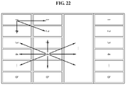
- FIG. 22 illustrates an example of a quantization method according to the fifth example embodiment.
- the encoding block 111 may set first subframes of 2D intra blocks to a macro block.
- the encoding block 111 may predict a correlation between macro blocks.
- the encoding block 111 may predict a correlation between a macro block 1 corresponding to a first macro block and other subframes adjacent to the macro block 1 . Also, the encoding block 111 may predict a correlation between a macro block corresponding to a fourth macro block and other subframes adjacent to the macro block 4 .
- the encoding block 111 may predict a correlation between a macro block currently being processed and a macro block that is separate therefrom by a predetermined interval, instead of using an adjacent macro block. For example, the encoding block 111 may predict a correlation between the macro block currently being processed and another macro block that is separate therefrom by a plurality of macro blocks.
- a probability of retrieving a macro block having an optimal correlation may increase, additional information such as location information of the other macro block that are separate by the plurality of macro blocks may be further used. Accordingly, a tradeoff may be present between a distance between macro blocks between which a correlation is to be measured and a probability of retrieving a macro block having an optimal correlation.
- the encoding block 111 may perform a DPCM on macro blocks corresponding to a highest predicted correlation.
- the encoding block 111 may quantize each of the macro blocks.
- the encoding block 111 may calculate a prediction gain based on a result of the DPCM and may quantize a residual signal between macro blocks corresponding to a highest correlation.
- FIG. 23 is a flowchart illustrating a method of an audio decoding method according to the fifth example embodiment.
- the decoding block 122 may extract an encoded 2D inter block and an encoded 2D intra block from a bitstream.
- the decoding block 122 may decode a 2D inter block from the encoded 2D inter block.
- the decoding block 122 may restore groups of frames of a residual signal from the 2D inter block decoded in operation 2310 .
- the decoding block 122 may generate frames of a frequency domain using the decoded 2D inter block in operation 2320 .
- the decoding block 122 may transform the frames of the frequency domain to frames of a time domain.
- the decoding block 122 may restore groups of frames that constitute the residual signal by releasing a window from the frames of the time domain.
- the decoding block 122 may restore the residual signal by performing an overlap-add process on the groups of the frames of the residual signal restored in operation 2320 .
- the decoding block 122 may convert an intra block bitstream to the encoded 2D intra block.
- the decoding block 122 may restore a before-encoding 2D intra block using the encoded 2D intra block converted in operation 2340 and the residual signal generated in operation 2330 .
- the residual signal may be a difference between the 2D intra blocks generated in operation 2010 as generated in operation 2030 and the 2D intra blocks encoded in operation 2020 . Accordingly, the decoding block 122 may restore the before-encoding 2D intra block by adding the residual signal to the encoded 2D intra block.
- the decoding block 122 may restore an audio signal using the before-encoding 2D intra block restored in operation 2350 .
- the decoding block may restore the audio signal that includes frame of input signal from the 2D intra block by performing operations 520 through 540 of FIG. 5 .
- FIG. 24 illustrates an example of an audio decoding process according to the fifth example embodiment.
- the decoding block 122 may receive an inter block bitstream that is converted from an encoded 2D inter block.
- the decoding block 122 may generate a residual signal 2401 from the inter block bitstream using an inter block decoder 2410 .
- the decoding block 122 may generate frames of a frequency domain using a decoded 2D inter block.
- the decoding block 122 may transform the frames of the frequency domain to frames of a time domain.
- the decoding block 122 may restore groups of frames that constitute a residual signal by releasing a window from the frames of the time domain.
- the decoding block 122 may restore the residual signal 2401 by performing an overlap-add process on the groups of the frames of the residual signal.
- the decoding block 122 may split the residual signal 2401 based on an intra block unit using an inter block splitter 2420 .
- the decoding block 122 may receive an intra block bitstream that is converted from an encoded 2D intra block.
- the decoding block 122 may convert the inter block bitstream to the encoded 2D inter block using an intra block decoder 2430 .
- the decoding block 122 may restore a before-encoding 2D intra block using the encoded 2D intra block and the residual signals split based on the intra block unit.
- the decoding block 122 may restore a before-encoding 2D intra block 2402 by adding the residual signal to the encoded 2D intra block.
- the before-encoding 2D intra block 2402 may be an intra block that includes a plurality of subframes.
- the decoding block 122 may restore an audio signal by combining the before-encoding 2D intra blocks 2402 using an intra block combiner 2440 .
- the decoding block may transform subframes of the frequency domain included in the 2D intra block 2402 to subframes of a time domain.
- the decoding block 122 may restore grouped subframes by releasing a window from the subframes of the time domain.
- the decoding block 122 may decode an audio signal 2400 that includes the frame of input signal by performing an overlap-add process on subframes included in a group and by sequentially determining frame of input signal 1 through 12 that constitute the audio signal 2400 .
- an encoding efficiency by reconfiguring and encoding an input audio signal as a 2D signal.
- the same framing structure as a video signal may be achieved using an encoding scheme that is interpreted based on a block unit, it is possible to flexibly perform homogeneity and synchronization of an encoding scheme compared to a conventional encoding method.
- the methods according to the above-described example embodiments may be recorded in non-transitory computer-readable media including program instructions to implement various operations of the above-described example embodiments.
- the media may also include, alone or in combination with the program instructions, data files, data structures, and the like.
- the program instructions recorded on the media may be those specially designed and constructed for the purposes of example embodiments, or they may be of the kind well-known and available to those having skill in the computer software arts.
- non-transitory computer-readable media examples include magnetic media such as hard disks, floppy disks, and magnetic tape; optical media such as CD-ROM discs and DVDs; magneto-optical media such as floptical discs; and hardware devices that are specially configured to store and perform program instructions, such as read-only memory (ROM), random access memory (RAM), flash memory (e.g., USB flash drives, memory cards, memory sticks, etc.), and the like.
- program instructions include both machine code, such as produced by a compiler, and files containing higher level code that may be executed by the computer using an interpreter.
- the above-described devices may be configured to act as one or more software modules in order to perform the operations of the above-described example embodiments, or vice versa.
Landscapes
- Engineering & Computer Science (AREA)
- Physics & Mathematics (AREA)
- Multimedia (AREA)
- Signal Processing (AREA)
- Computational Linguistics (AREA)
- Health & Medical Sciences (AREA)
- Audiology, Speech & Language Pathology (AREA)
- Human Computer Interaction (AREA)
- Acoustics & Sound (AREA)
- Spectroscopy & Molecular Physics (AREA)
- Compression, Expansion, Code Conversion, And Decoders (AREA)
- Compression Or Coding Systems Of Tv Signals (AREA)
Abstract
Description
Claims (9)
Applications Claiming Priority (3)
| Application Number | Priority Date | Filing Date | Title |
|---|---|---|---|
| KR10-2016-0033627 | 2016-03-21 | ||
| KR1020160033627A KR102546098B1 (en) | 2016-03-21 | 2016-03-21 | Apparatus and method for encoding / decoding audio based on block |
| PCT/KR2017/002995 WO2017164606A2 (en) | 2016-03-21 | 2017-03-21 | Block-based audio encoding/decoding device and method therefor |
Publications (2)
| Publication Number | Publication Date |
|---|---|
| US20190035412A1 US20190035412A1 (en) | 2019-01-31 |
| US10839819B2 true US10839819B2 (en) | 2020-11-17 |
Family
ID=59900470
Family Applications (1)
| Application Number | Title | Priority Date | Filing Date |
|---|---|---|---|
| US16/081,169 Active 2037-09-04 US10839819B2 (en) | 2016-03-21 | 2017-03-21 | Block-based audio encoding/decoding device and method therefor |
Country Status (3)
| Country | Link |
|---|---|
| US (1) | US10839819B2 (en) |
| KR (1) | KR102546098B1 (en) |
| WO (1) | WO2017164606A2 (en) |
Families Citing this family (1)
| Publication number | Priority date | Publication date | Assignee | Title |
|---|---|---|---|---|
| KR102546098B1 (en) * | 2016-03-21 | 2023-06-22 | 한국전자통신연구원 | Apparatus and method for encoding / decoding audio based on block |
Citations (18)
| Publication number | Priority date | Publication date | Assignee | Title |
|---|---|---|---|---|
| US7272556B1 (en) * | 1998-09-23 | 2007-09-18 | Lucent Technologies Inc. | Scalable and embedded codec for speech and audio signals |
| US20080122862A1 (en) | 2006-11-24 | 2008-05-29 | Samsung Electronics Co., Ltd. | Method and apparatus for transmitting and receiving moving pictures based on rgb codec |
| US20090044230A1 (en) * | 2007-07-02 | 2009-02-12 | Lg Electronics Inc. | Broadcasting receiver and broadcast signal processing method |
| US20090044072A1 (en) * | 2007-07-02 | 2009-02-12 | Lg Electronics Inc. | Broadcasting receiver and broadcast signal processing method |
| US20090040997A1 (en) * | 2007-07-02 | 2009-02-12 | Lg Electronics Inc. | Broadcasting receiver and broadcast signal processing method |
| US20090044231A1 (en) * | 2007-07-02 | 2009-02-12 | Lg Electronics Inc. | Broadcasting receiver and broadcast singnal processing method |
| US20090046815A1 (en) * | 2007-07-02 | 2009-02-19 | Lg Electronics Inc. | Broadcasting receiver and broadcast signal processing method |
| US20100070285A1 (en) * | 2008-07-07 | 2010-03-18 | Lg Electronics Inc. | method and an apparatus for processing an audio signal |
| US7885819B2 (en) * | 2007-06-29 | 2011-02-08 | Microsoft Corporation | Bitstream syntax for multi-process audio decoding |
| US20110295598A1 (en) * | 2010-06-01 | 2011-12-01 | Qualcomm Incorporated | Systems, methods, apparatus, and computer program products for wideband speech coding |
| US20120209600A1 (en) | 2009-10-14 | 2012-08-16 | Kwangwoon University Industry-Academic Collaboration Foundation | Integrated voice/audio encoding/decoding device and method whereby the overlap region of a window is adjusted based on the transition interval |
| US8290782B2 (en) | 2008-07-24 | 2012-10-16 | Dts, Inc. | Compression of audio scale-factors by two-dimensional transformation |
| US20130094411A1 (en) * | 2010-02-17 | 2013-04-18 | Zte Corporation | Methods and systems for csi-rs transmission in lte-advance systems |
| US8532983B2 (en) * | 2008-09-06 | 2013-09-10 | Huawei Technologies Co., Ltd. | Adaptive frequency prediction for encoding or decoding an audio signal |
| US20140366093A1 (en) | 2013-06-10 | 2014-12-11 | Electronics And Telecommunications Research Institute | Apparatus and method for virtual desktop service |
| US20150156578A1 (en) * | 2012-09-26 | 2015-06-04 | Foundation for Research and Technology - Hellas (F.O.R.T.H) Institute of Computer Science (I.C.S.) | Sound source localization and isolation apparatuses, methods and systems |
| US20160055855A1 (en) * | 2013-04-05 | 2016-02-25 | Dolby Laboratories Licensing Corporation | Audio processing system |
| US20190035412A1 (en) * | 2016-03-21 | 2019-01-31 | Electronics And Telecommunications Research Institute | Block-based audio encoding/decoding device and method therefor |
Family Cites Families (6)
| Publication number | Priority date | Publication date | Assignee | Title |
|---|---|---|---|---|
| KR101037931B1 (en) * | 2004-05-13 | 2011-05-30 | 삼성전자주식회사 | Speech signal compression and decompression device and its method using two-dimensional data processing |
| US7418394B2 (en) * | 2005-04-28 | 2008-08-26 | Dolby Laboratories Licensing Corporation | Method and system for operating audio encoders utilizing data from overlapping audio segments |
| KR101441896B1 (en) * | 2008-01-29 | 2014-09-23 | 삼성전자주식회사 | Method and apparatus for encoding/decoding audio signal using adaptive LPC coefficient interpolation |
| JP5942358B2 (en) * | 2011-08-24 | 2016-06-29 | ソニー株式会社 | Encoding apparatus and method, decoding apparatus and method, and program |
| CN104718572B (en) * | 2012-06-04 | 2018-07-31 | 三星电子株式会社 | Audio coding method and device, audio-frequency decoding method and device and the multimedia device using this method and device |
| EP3961622B1 (en) * | 2013-05-24 | 2023-11-01 | Dolby International AB | Audio encoder |
-
2016
- 2016-03-21 KR KR1020160033627A patent/KR102546098B1/en active Active
-
2017
- 2017-03-21 WO PCT/KR2017/002995 patent/WO2017164606A2/en not_active Ceased
- 2017-03-21 US US16/081,169 patent/US10839819B2/en active Active
Patent Citations (21)
| Publication number | Priority date | Publication date | Assignee | Title |
|---|---|---|---|---|
| US7272556B1 (en) * | 1998-09-23 | 2007-09-18 | Lucent Technologies Inc. | Scalable and embedded codec for speech and audio signals |
| US20080122862A1 (en) | 2006-11-24 | 2008-05-29 | Samsung Electronics Co., Ltd. | Method and apparatus for transmitting and receiving moving pictures based on rgb codec |
| US7885819B2 (en) * | 2007-06-29 | 2011-02-08 | Microsoft Corporation | Bitstream syntax for multi-process audio decoding |
| US20120323584A1 (en) * | 2007-06-29 | 2012-12-20 | Microsoft Corporation | Bitstream syntax for multi-process audio decoding |
| US8645146B2 (en) * | 2007-06-29 | 2014-02-04 | Microsoft Corporation | Bitstream syntax for multi-process audio decoding |
| US20090044072A1 (en) * | 2007-07-02 | 2009-02-12 | Lg Electronics Inc. | Broadcasting receiver and broadcast signal processing method |
| US20090046815A1 (en) * | 2007-07-02 | 2009-02-19 | Lg Electronics Inc. | Broadcasting receiver and broadcast signal processing method |
| US20090044231A1 (en) * | 2007-07-02 | 2009-02-12 | Lg Electronics Inc. | Broadcasting receiver and broadcast singnal processing method |
| US20090040997A1 (en) * | 2007-07-02 | 2009-02-12 | Lg Electronics Inc. | Broadcasting receiver and broadcast signal processing method |
| US20090044230A1 (en) * | 2007-07-02 | 2009-02-12 | Lg Electronics Inc. | Broadcasting receiver and broadcast signal processing method |
| US20100070285A1 (en) * | 2008-07-07 | 2010-03-18 | Lg Electronics Inc. | method and an apparatus for processing an audio signal |
| US8380523B2 (en) * | 2008-07-07 | 2013-02-19 | Lg Electronics Inc. | Method and an apparatus for processing an audio signal |
| US8290782B2 (en) | 2008-07-24 | 2012-10-16 | Dts, Inc. | Compression of audio scale-factors by two-dimensional transformation |
| US8532983B2 (en) * | 2008-09-06 | 2013-09-10 | Huawei Technologies Co., Ltd. | Adaptive frequency prediction for encoding or decoding an audio signal |
| US20120209600A1 (en) | 2009-10-14 | 2012-08-16 | Kwangwoon University Industry-Academic Collaboration Foundation | Integrated voice/audio encoding/decoding device and method whereby the overlap region of a window is adjusted based on the transition interval |
| US20130094411A1 (en) * | 2010-02-17 | 2013-04-18 | Zte Corporation | Methods and systems for csi-rs transmission in lte-advance systems |
| US20110295598A1 (en) * | 2010-06-01 | 2011-12-01 | Qualcomm Incorporated | Systems, methods, apparatus, and computer program products for wideband speech coding |
| US20150156578A1 (en) * | 2012-09-26 | 2015-06-04 | Foundation for Research and Technology - Hellas (F.O.R.T.H) Institute of Computer Science (I.C.S.) | Sound source localization and isolation apparatuses, methods and systems |
| US20160055855A1 (en) * | 2013-04-05 | 2016-02-25 | Dolby Laboratories Licensing Corporation | Audio processing system |
| US20140366093A1 (en) | 2013-06-10 | 2014-12-11 | Electronics And Telecommunications Research Institute | Apparatus and method for virtual desktop service |
| US20190035412A1 (en) * | 2016-03-21 | 2019-01-31 | Electronics And Telecommunications Research Institute | Block-based audio encoding/decoding device and method therefor |
Non-Patent Citations (2)
| Title |
|---|
| International Search Report dated Jun. 19, 2017, in corresponding International Application No. PCT/KR2017/002995 (3 pages in English, 3 pages in Korean). |
| Johnston, Jmaes D., "Transform coding of Audio Signals Using Perceptual Noise Criteria" Journal of Selected Areas in Communications, vol. 6 No. 2, Feb. 1988, pp. 314-323 (10 pages in English). |
Also Published As
| Publication number | Publication date |
|---|---|
| WO2017164606A3 (en) | 2018-08-02 |
| KR102546098B1 (en) | 2023-06-22 |
| WO2017164606A2 (en) | 2017-09-28 |
| KR20170109456A (en) | 2017-09-29 |
| US20190035412A1 (en) | 2019-01-31 |
Similar Documents
| Publication | Publication Date | Title |
|---|---|---|
| KR101428487B1 (en) | Multi-channel encoding and decoding method and apparatus | |
| US7774205B2 (en) | Coding of sparse digital media spectral data | |
| US7761290B2 (en) | Flexible frequency and time partitioning in perceptual transform coding of audio | |
| CN1135721C (en) | Audio signal coding method and apparatus | |
| JP2023098967A (en) | Context-Based Entropy Coding of Spectral Envelope Sample Values | |
| USRE46082E1 (en) | Method and apparatus for low bit rate encoding and decoding | |
| CN100477531C (en) | Encoding method for compression encoding of multi-channel digital audio signal | |
| JP5404412B2 (en) | Encoding device, decoding device and methods thereof | |
| CN102201238B (en) | Method and apparatus for encoding and decoding excitation patterns | |
| JP5695074B2 (en) | Speech coding apparatus and speech decoding apparatus | |
| US9454972B2 (en) | Audio and speech coding device, audio and speech decoding device, method for coding audio and speech, and method for decoding audio and speech | |
| KR102512359B1 (en) | Energy lossless-encoding method and apparatus, signal encoding method and apparatus, energy lossless-decoding method and apparatus, and signal decoding method and apparatus | |
| WO2009048239A2 (en) | Encoding and decoding method using variable subband analysis and apparatus thereof | |
| CN107610710A (en) | A kind of audio coding and coding/decoding method towards Multi-audio-frequency object | |
| US9240192B2 (en) | Device and method for efficiently encoding quantization parameters of spectral coefficient coding | |
| CN105659320A (en) | Audio encoder and decoder | |
| KR100945219B1 (en) | Processing of Encoded Signals | |
| US10839819B2 (en) | Block-based audio encoding/decoding device and method therefor | |
| Yu et al. | A scalable lossy to lossless audio coder for MPEG-4 lossless audio coding | |
| KR20070011136A (en) | Channel Difference Quantization and Dequantization Method Based on Virtual Source Location Information | |
| CN104380377B (en) | For the method and apparatus of scalable low encoding complexity/decoding | |
| KR20100114450A (en) | Apparatus for high quality multiple audio object coding and decoding using residual coding with variable bitrate | |
| Namazi et al. | On ultra low-delay compression of higher order ambisonics signals | |
| JP2008268792A (en) | Audio signal encoding apparatus and bit rate conversion apparatus thereof | |
| CN103035249A (en) | An Audio Arithmetic Coding Method Based on Time-Frequency Plane Context |
Legal Events
| Date | Code | Title | Description |
|---|---|---|---|
| FEPP | Fee payment procedure |
Free format text: ENTITY STATUS SET TO UNDISCOUNTED (ORIGINAL EVENT CODE: BIG.); ENTITY STATUS OF PATENT OWNER: SMALL ENTITY |
|
| FEPP | Fee payment procedure |
Free format text: ENTITY STATUS SET TO SMALL (ORIGINAL EVENT CODE: SMAL); ENTITY STATUS OF PATENT OWNER: SMALL ENTITY |
|
| STPP | Information on status: patent application and granting procedure in general |
Free format text: DOCKETED NEW CASE - READY FOR EXAMINATION |
|
| AS | Assignment |
Owner name: ELECTRONICS AND TELECOMMUNICATIONS RESEARCH INSTIT Free format text: ASSIGNMENT OF ASSIGNORS INTEREST;ASSIGNORS:BEACK, SEUNG KWON;LEE, TAE JIN;SUNG, JONGMO;AND OTHERS;REEL/FRAME:050689/0093 Effective date: 20190829 Owner name: ELECTRONICS AND TELECOMMUNICATIONS RESEARCH INSTITUTE, KOREA, REPUBLIC OF Free format text: ASSIGNMENT OF ASSIGNORS INTEREST;ASSIGNORS:BEACK, SEUNG KWON;LEE, TAE JIN;SUNG, JONGMO;AND OTHERS;REEL/FRAME:050689/0093 Effective date: 20190829 |
|
| STPP | Information on status: patent application and granting procedure in general |
Free format text: NON FINAL ACTION MAILED |
|
| STPP | Information on status: patent application and granting procedure in general |
Free format text: PUBLICATIONS -- ISSUE FEE PAYMENT VERIFIED |
|
| STCF | Information on status: patent grant |
Free format text: PATENTED CASE |
|
| MAFP | Maintenance fee payment |
Free format text: PAYMENT OF MAINTENANCE FEE, 4TH YR, SMALL ENTITY (ORIGINAL EVENT CODE: M2551); ENTITY STATUS OF PATENT OWNER: SMALL ENTITY Year of fee payment: 4 |