US10837726B2 - Methods and apparatus for sealed trigger housing - Google Patents
Methods and apparatus for sealed trigger housing Download PDFInfo
- Publication number
- US10837726B2 US10837726B2 US16/575,288 US201916575288A US10837726B2 US 10837726 B2 US10837726 B2 US 10837726B2 US 201916575288 A US201916575288 A US 201916575288A US 10837726 B2 US10837726 B2 US 10837726B2
- Authority
- US
- United States
- Prior art keywords
- trigger
- seal
- housing
- hammer
- selector
- Prior art date
- Legal status (The legal status is an assumption and is not a legal conclusion. Google has not performed a legal analysis and makes no representation as to the accuracy of the status listed.)
- Active
Links
- 238000000034 method Methods 0.000 title abstract description 11
- 238000007789 sealing Methods 0.000 claims abstract description 14
- 230000007246 mechanism Effects 0.000 claims description 13
- 238000005516 engineering process Methods 0.000 abstract description 35
- 230000008901 benefit Effects 0.000 description 8
- 238000012986 modification Methods 0.000 description 5
- 230000004048 modification Effects 0.000 description 5
- 238000010304 firing Methods 0.000 description 4
- 239000000463 material Substances 0.000 description 3
- 230000008569 process Effects 0.000 description 3
- 230000007257 malfunction Effects 0.000 description 2
- 238000004519 manufacturing process Methods 0.000 description 2
- 239000000203 mixture Substances 0.000 description 2
- 239000004033 plastic Substances 0.000 description 2
- 230000004044 response Effects 0.000 description 2
- 230000003213 activating effect Effects 0.000 description 1
- 239000000919 ceramic Substances 0.000 description 1
- 239000002131 composite material Substances 0.000 description 1
- 238000007796 conventional method Methods 0.000 description 1
- 230000008878 coupling Effects 0.000 description 1
- 238000010168 coupling process Methods 0.000 description 1
- 238000005859 coupling reaction Methods 0.000 description 1
- 238000013461 design Methods 0.000 description 1
- 239000000428 dust Substances 0.000 description 1
- 239000002184 metal Substances 0.000 description 1
- 239000013618 particulate matter Substances 0.000 description 1
- 229920000642 polymer Polymers 0.000 description 1
- 238000012545 processing Methods 0.000 description 1
- 239000005060 rubber Substances 0.000 description 1
- 239000004576 sand Substances 0.000 description 1
Images


Classifications
-
- F—MECHANICAL ENGINEERING; LIGHTING; HEATING; WEAPONS; BLASTING
- F41—WEAPONS
- F41A—FUNCTIONAL FEATURES OR DETAILS COMMON TO BOTH SMALLARMS AND ORDNANCE, e.g. CANNONS; MOUNTINGS FOR SMALLARMS OR ORDNANCE
- F41A19/00—Firing or trigger mechanisms; Cocking mechanisms
- F41A19/06—Mechanical firing mechanisms, e.g. counterrecoil firing, recoil actuated firing mechanisms
- F41A19/15—Modular firing mechanism units
-
- F—MECHANICAL ENGINEERING; LIGHTING; HEATING; WEAPONS; BLASTING
- F41—WEAPONS
- F41A—FUNCTIONAL FEATURES OR DETAILS COMMON TO BOTH SMALLARMS AND ORDNANCE, e.g. CANNONS; MOUNTINGS FOR SMALLARMS OR ORDNANCE
- F41A19/00—Firing or trigger mechanisms; Cocking mechanisms
- F41A19/06—Mechanical firing mechanisms, e.g. counterrecoil firing, recoil actuated firing mechanisms
- F41A19/10—Triggers; Trigger mountings
-
- F—MECHANICAL ENGINEERING; LIGHTING; HEATING; WEAPONS; BLASTING
- F41—WEAPONS
- F41A—FUNCTIONAL FEATURES OR DETAILS COMMON TO BOTH SMALLARMS AND ORDNANCE, e.g. CANNONS; MOUNTINGS FOR SMALLARMS OR ORDNANCE
- F41A35/00—Accessories or details not otherwise provided for
- F41A35/02—Dust- or weather-protection caps or covers
Definitions
- Trigger mechanisms of firearms include multiple working components such as a sear, hammer, trigger, springs, and pins that are commonly positioned within a trigger housing.
- the working components are configured to move in relation to each other to allow the firearm to properly fire the round of the firearm.
- trigger housings enclose the working components the housing is not typically sealed to prevent foreign debris from getting into the interior of the trigger housing.
- Components that protrude outwardly from the trigger housing are components that generally rotate or pivot during operation. Similarly, components positioned completely within the trigger housing are configured to move, pivot, compress, and/or lock in place during normal operation of the firearm. If debris such as sand, dust, or other like small particulate matter gets into the trigger housing the moving parts may be prevented from moving properly causing the firearm to malfunction. Certain types of malfunctions require that the entire trigger assembly of the firearm be disassembled and cleaned before the firearm will function properly again.
- a sealed trigger housing is configured to provide a more effective method of preventing foreign debris from entering the trigger housing.
- Various embodiments of the sealed trigger housing comprise a pair of side plates configured to at least partially house a trigger, a hammer, and a selector switch within an interior portion of the trigger housing.
- a plurality of seals may be used to create seals around any component that protrudes outwardly from the trigger housing.
- FIG. 1 representatively illustrates a front perspective view of a sealed trigger housing in accordance with an exemplary embodiment of the present technology
- FIG. 2 representatively illustrates a bottom rear perspective view of the sealed trigger housing in accordance with an exemplary embodiment of the present technology
- FIG. 3 representatively illustrates a rear top perspective view of the sealed trigger housing in accordance with an exemplary embodiment of the present technology
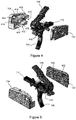
- FIG. 4 representatively illustrates an exploded view of the sealed trigger housing in accordance with an exemplary embodiment of the present technology
- FIG. 5 representatively illustrates an exploded view of the sealed trigger housing in accordance with an exemplary embodiment of the present technology
- FIG. 6 representatively illustrates a detailed view of a housing plate in accordance with an exemplary embodiment of the present technology
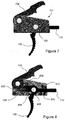
- FIG. 7 representatively illustrates a side view of the sealed trigger housing in accordance with an exemplary embodiment of the present technology.
- FIG. 8 representatively illustrates a side view of sealed trigger housing with a side plate removed in accordance with an exemplary embodiment of the present technology
- FIG. 9 representatively illustrates a perspective view of an alternative embodiment of a housing plate in accordance with an exemplary embodiment of the present technology.
- FIG. 10 representatively illustrates a perspective view of an alternative embodiment of an opposing housing plate to that shown in FIG. 9 in accordance with an exemplary embodiment of the present technology.
- the present technology may be described in terms of functional block components and various processing steps. Such functional blocks may be realized by any number of components configured to perform the specified functions and achieve the various results.
- the present technology may employ various materials, finishes, dimensions, and geometries, which may carry out a variety of operations suited to a specified application or environment.
- the present technology may be practiced in conjunction with any number of systems configured for operation with firearms, and the system described is merely one exemplary application for the technology.
- the present technology may employ any number of conventional techniques for sealing, preventing intrusion of foreign object debris, and the like.
- Methods and apparatus for a sealed trigger housing may operate in conjunction with any type of semi-automatic or automatic firearm.
- Various representative implementations of the present technology may be applied to any type of firearm including a hand gun or rifle and may be retrofit into various types of existing firearms.
- the sealed trigger housing may be used as a “drop in” replacement for a trigger originally installed on a firearm.
- a sealed trigger housing 100 may generally comprise a trigger housing 101 comprising a first housing plate 102 and a second housing plate 104 .
- the trigger housing 101 is configured to at least partially house one or more trigger mechanism components such as a trigger 106 , a hammer 108 , and a selector switch 110 within an interior volume of the trigger housing 101 .
- the trigger housing 101 may also fully enclose additional working components or moving parts such as springs, pins, a sear link, and a main sear that functionally link the trigger 106 to the hammer 108 and the selector switch 110 .
- the trigger 106 is used to selectively release the hammer 108 from a first position allowing it to rotate and strike a projectile causing the projectile to be fired from the firearm.
- the trigger 106 may comprise any suitable device or system for activating the hammer 108 .
- At least one surface of the trigger 106 may be configured to at least partially conform to a portion of a user's finger and be configured to rotate about a pivot point within the trigger housing 101 in response to a pressure force being applied to the trigger 106 by the user's finger.
- the hammer 108 rotates from a first position to strike a firing pin (not shown) on the ammunition round (not shown). Upon firing of the round, recoil forces are used to return the hammer 108 to the first position.
- the hammer 108 may comprise any suitable device or system for causing the round to be fired in response to a force being applied to the trigger 106 .
- the hammer 108 may comprise a body having a first end portion with a surface configured to contact a firing pin of the ammunition round and a second end portion having a hole therethrough about which the hammer 108 rotates.
- the hammer 108 may be coupled to the trigger 106 by a pin or sleeve configured to extend from a first side of the trigger housing 101 , through the hole, and to a second side of the trigger housing 101 . The hammer 108 may then rotate about the hole and the second sleeve during the actuation cycle.
- the first housing plate 102 and the second housing plate 104 are configured to form a seal when coupled together.
- the trigger housing 101 of the present technology seals off interior components within the interior portion of the trigger housing 101 .
- the first housing plate 102 may comprise a first recess 502 and the second housing plate 104 may comprise a second recesses 408 configured to receive, conform to, or otherwise fit around one or more trigger mechanism components.
- the first recess 502 may be configured to receive a first side of a hammer spring 416 and the second recess 408 may be configured to receive an opposing second side of the hammer spring 416 .
- the first housing plate 102 and the second housing plate 104 may abut each other when coupled together such that the interior of the trigger housing 101 is at least partially closed off from the exterior environment.
- the first housing plate 102 and the second housing plate 104 may be configured in any suitable manner to create a seal.
- an interior facing surface 504 of the first housing plate 102 may fit flush against one or more interior facing surfaces of the second housing plate 104 to seal the trigger housing 101 .
- the second housing plate 104 may comprise an upper cover portion 402 , a lower trigger portion 406 , and a lower spring portion 404 that extend outward from an interior facing surface 418 of the second housing plate 104 .
- the interior facing surface 504 of the first housing plate 102 may be configured to abut against the upper cover portion 402 , lower trigger portion 406 , and lower spring portion 404 of the second housing plate 104 to effectively form a seal between the surfaces when connected together.
- the trigger housing 101 may comprise a trigger opening 410 disposed between the lower trigger portion 406 and the lower spring portion 404 of the second housing plate 104 and a hammer opening 414 may be positioned between the upper cover portion 402 and the lower spring portion 404 of the second housing plate 104 .
- the trigger housing 101 may further comprise a selector opening 412 disposed between the upper cover portion 402 and the lower trigger portion 406 of the second housing plate 104 . Additional openings may be required according to a particular trigger assembly.
- the interior surfaces of the first housing plate 102 and the second housing plate 104 may also be configured to create an enhanced seal.
- the first housing plate 102 , the upper cover portion 402 , the lower trigger portion 406 , and the lower spring portion 404 of the second housing plate 104 may comprise a beveled lip around their perimeters to create an enhanced seal.
- an outer edge of the interior surface of the first housing plate 102 may comprise a raised surface 1002 and the exterior edges of the upper cover portion 402 , the lower trigger portion 406 , and the lower spring portion 404 may comprise a recess or channel 902 configured to receive the raised surface on the first housing plate 102 .
- the raised surface and the channel may make it more difficult for debris to pass into the interior of the trigger housing 101 and may also have the added benefit of helping lock the first housing plate 102 and the second housing plate 104 together during assembly.
- the trigger housing 101 may further comprise a sealing system configured to provide a seal around any protruding components to inhibit or prevent foreign debris from getting into the interior of the trigger housing 101 .
- the sealing system may incorporate a plurality of sealing elements to create a seal around any component that protrudes outwardly from the trigger housing 101 .
- the plurality of sealing elements may comprise any suitable material capable of providing a seal to prevent or otherwise limit debris from passing into the interior of the trigger housing 101 such as polymers, rubber, plastic, ceramic, metal, composites, or the like.
- the hammer 108 rotates in both clockwise and counter-clockwise directions during the firing cycle. Because the hammer 108 rotates about a fixed location and protrudes outwardly from the trigger housing 101 , the hammer opening 414 exists between the hammer 108 and the trigger housing 101 body otherwise rotation of the hammer 108 could be inhibited.
- a first hammer seal 802 may be positioned in a first hammer seal recess 602 disposed along an upper edge of the lower trigger portion 404 and a second hammer seal 804 may be positioned in a second hammer seal recess 604 disposed along a forward edge of the upper cover portion 402 , wherein the first and second hammer seals 802 , 804 contact the hammer 108 when the trigger housing 101 is fully assembled.
- a first trigger seal 806 may be positioned in a first trigger seal recess 606 disposed along a rear edge of the lower trigger portion 404 and a second trigger seal 808 may be positioned in a second trigger seal recess 608 disposed along a forward edge of the lower trigger portion 406 , wherein the first and second trigger seals 806 , 808 contact the trigger 106 when the trigger housing 101 is fully assembled.
- a first selector seal 810 may be positioned in a first selector seal recess 610 disposed along an upper edge of the lower trigger portion 404 and a second selector seal 812 may be positioned in a second selector seal recess 612 disposed along a lower edge of the upper cover portion 404 , wherein the first and second selector seals 810 , 812 contact the selector switch 110 when the trigger housing 101 is fully assembled.
- the plurality of seals 802 , 804 , 806 , 808 , 810 , 812 are configured to press against the protruding components to allow motion while reducing the ability of debris to enter the trigger housing 101 around these components.
- each of the plurality of seals 802 , 804 , 806 , 808 , 810 , 812 may comprise a rubberized pin that may be positioned in the plurality of recesses 602 , 604 , 606 , 608 , 610 , 612 .
- the plurality of seals 802 , 804 , 806 , 808 , 810 , 812 may each comprise a stiff plastic pin.
- any apparatus embodiment may be assembled or otherwise operationally configured in a variety of permutations to produce substantially the same result as the present technology and are accordingly not limited to the specific configuration recited in the specific examples.
- Benefits, other advantages and solutions to problems have been described above with regard to particular embodiments; however, any benefit, advantage, solution to problems or any element that may cause any particular benefit, advantage or solution to occur or to become more pronounced are not to be construed as critical, required or essential features or components.
- the terms “comprises,” “comprising,” or any variation thereof, are intended to reference a non-exclusive inclusion, such that a process, method, article, composition or apparatus that comprises a list of elements does not include only those elements recited, but may also include other elements not expressly listed or inherent to such process, method, article, composition or apparatus.
- Other combinations and/or modifications of the above-described structures, arrangements, applications, proportions, elements, materials or components used in the practice of the present technology, in addition to those not specifically recited, may be varied or otherwise particularly adapted to specific environments, manufacturing specifications, design parameters or other operating requirements without departing from the general principles of the same.
Landscapes
- Engineering & Computer Science (AREA)
- General Engineering & Computer Science (AREA)
- Percussive Tools And Related Accessories (AREA)
Abstract
Description
Claims (11)
Priority Applications (1)
| Application Number | Priority Date | Filing Date | Title |
|---|---|---|---|
| US16/575,288 US10837726B2 (en) | 2018-09-18 | 2019-09-18 | Methods and apparatus for sealed trigger housing |
Applications Claiming Priority (2)
| Application Number | Priority Date | Filing Date | Title |
|---|---|---|---|
| US201862732717P | 2018-09-18 | 2018-09-18 | |
| US16/575,288 US10837726B2 (en) | 2018-09-18 | 2019-09-18 | Methods and apparatus for sealed trigger housing |
Publications (2)
| Publication Number | Publication Date |
|---|---|
| US20200088485A1 US20200088485A1 (en) | 2020-03-19 |
| US10837726B2 true US10837726B2 (en) | 2020-11-17 |
Family
ID=69773872
Family Applications (1)
| Application Number | Title | Priority Date | Filing Date |
|---|---|---|---|
| US16/575,288 Active US10837726B2 (en) | 2018-09-18 | 2019-09-18 | Methods and apparatus for sealed trigger housing |
Country Status (1)
| Country | Link |
|---|---|
| US (1) | US10837726B2 (en) |
Families Citing this family (2)
| Publication number | Priority date | Publication date | Assignee | Title |
|---|---|---|---|---|
| US10837728B2 (en) * | 2018-02-20 | 2020-11-17 | Krl Holding Company, Inc. | Two-stage, drop-in trigger assembly |
| USD1024253S1 (en) * | 2020-07-03 | 2024-04-23 | In Ovation Llc | Trigger cassette |
Citations (6)
| Publication number | Priority date | Publication date | Assignee | Title |
|---|---|---|---|---|
| US7293385B2 (en) * | 2002-05-21 | 2007-11-13 | Mccormick Michael L | Modular trigger group for firearms and firearm having a modular trigger group |
| US7587851B1 (en) * | 2006-09-18 | 2009-09-15 | Dpms Firearms, Llc | Receiver gasket |
| US20110173859A1 (en) * | 2010-01-15 | 2011-07-21 | Smith & Wesson Corp. | Removable trigger guard |
| US20170191776A1 (en) * | 2015-04-17 | 2017-07-06 | Serge Dextraze | Multi-stage trigger mechanism for firearm |
| US20180003457A1 (en) * | 2016-06-30 | 2018-01-04 | Palmetto State Armory, LLC | Caliber modification using modular fire control group |
| US10401107B2 (en) | 2017-02-10 | 2019-09-03 | M&M Mfg Llc | Trigger mechanism for a firearm |
-
2019
- 2019-09-18 US US16/575,288 patent/US10837726B2/en active Active
Patent Citations (6)
| Publication number | Priority date | Publication date | Assignee | Title |
|---|---|---|---|---|
| US7293385B2 (en) * | 2002-05-21 | 2007-11-13 | Mccormick Michael L | Modular trigger group for firearms and firearm having a modular trigger group |
| US7587851B1 (en) * | 2006-09-18 | 2009-09-15 | Dpms Firearms, Llc | Receiver gasket |
| US20110173859A1 (en) * | 2010-01-15 | 2011-07-21 | Smith & Wesson Corp. | Removable trigger guard |
| US20170191776A1 (en) * | 2015-04-17 | 2017-07-06 | Serge Dextraze | Multi-stage trigger mechanism for firearm |
| US20180003457A1 (en) * | 2016-06-30 | 2018-01-04 | Palmetto State Armory, LLC | Caliber modification using modular fire control group |
| US10401107B2 (en) | 2017-02-10 | 2019-09-03 | M&M Mfg Llc | Trigger mechanism for a firearm |
Non-Patent Citations (1)
| Title |
|---|
| SLT-1 Trigger. <https://forums.brianenos.com/topic/248403-new-slt-1-trigger/>. Apr. 30, 2017. (Year: 2017). * |
Also Published As
| Publication number | Publication date |
|---|---|
| US20200088485A1 (en) | 2020-03-19 |
Similar Documents
| Publication | Publication Date | Title |
|---|---|---|
| US10837726B2 (en) | Methods and apparatus for sealed trigger housing | |
| JP6208861B2 (en) | Disassembly protection device for automatic handgun, and automatic handgun equipped with disassembly protection device | |
| US10401107B2 (en) | Trigger mechanism for a firearm | |
| US10254067B2 (en) | Trigger-locking apparatus, system, and method for semiautomatic firearms | |
| US10584932B2 (en) | Trigger-locking apparatus, system, and method for semiautomatic firearms | |
| US11326848B2 (en) | Fire control/trigger mechanism | |
| US2940201A (en) | Bolt actuated cover for ejection ports in firearm receivers | |
| US9052150B2 (en) | Firearm trigger mechanism, firearm and method of controlling a rate of the firearm | |
| AU2015247247A1 (en) | Linear repeating firearm, with assisted ejection | |
| US20250383172A1 (en) | Machine gun trigger with select fire | |
| US10222159B1 (en) | Firearm safety | |
| US2425684A (en) | Breech bolt for firearms | |
| US3477162A (en) | Extractor system with a single spring exerting unequal forces upon two firearm extractors | |
| US7275472B1 (en) | Gas ring for firearm | |
| US20250237451A1 (en) | Firearm side casing ejection assembly and related techniques | |
| US2894346A (en) | Firing mechanism with a single spring for the hammer, hammer catch means and trigger | |
| CN102227606B (en) | Trigger mechanism for sporting rifle | |
| US12372315B2 (en) | Firearm frame with a relief | |
| US11808540B2 (en) | Safety mechanism for blowback firearm | |
| TWI833625B (en) | Modular bolt carrier group | |
| US3027811A (en) | Fire control mechanism for reciprocating bolt firearms | |
| RU2246676C1 (en) | Locking device | |
| US20250237452A1 (en) | Pistol and trigger for a pistol | |
| US11054205B1 (en) | Trigger device with over travel stop | |
| EP2541185B1 (en) | Closure for break-action firearms |
Legal Events
| Date | Code | Title | Description |
|---|---|---|---|
| FEPP | Fee payment procedure |
Free format text: ENTITY STATUS SET TO UNDISCOUNTED (ORIGINAL EVENT CODE: BIG.); ENTITY STATUS OF PATENT OWNER: SMALL ENTITY |
|
| FEPP | Fee payment procedure |
Free format text: ENTITY STATUS SET TO SMALL (ORIGINAL EVENT CODE: SMAL); ENTITY STATUS OF PATENT OWNER: SMALL ENTITY |
|
| STPP | Information on status: patent application and granting procedure in general |
Free format text: NON FINAL ACTION MAILED |
|
| STPP | Information on status: patent application and granting procedure in general |
Free format text: NOTICE OF ALLOWANCE MAILED -- APPLICATION RECEIVED IN OFFICE OF PUBLICATIONS |
|
| STPP | Information on status: patent application and granting procedure in general |
Free format text: PUBLICATIONS -- ISSUE FEE PAYMENT RECEIVED |
|
| STPP | Information on status: patent application and granting procedure in general |
Free format text: PUBLICATIONS -- ISSUE FEE PAYMENT VERIFIED |
|
| STCF | Information on status: patent grant |
Free format text: PATENTED CASE |
|
| AS | Assignment |
Owner name: M&M MFG LLC, ARIZONA Free format text: ASSIGNMENT OF ASSIGNORS INTEREST;ASSIGNOR:MARTINEZ, MICHAEL;REEL/FRAME:054985/0800 Effective date: 20210121 |
|
| MAFP | Maintenance fee payment |
Free format text: PAYMENT OF MAINTENANCE FEE, 4TH YR, SMALL ENTITY (ORIGINAL EVENT CODE: M2551); ENTITY STATUS OF PATENT OWNER: SMALL ENTITY Year of fee payment: 4 |