US10834176B2 - Automated end-to-end application deployment in a data center - Google Patents
Automated end-to-end application deployment in a data center Download PDFInfo
- Publication number
- US10834176B2 US10834176B2 US15/455,919 US201715455919A US10834176B2 US 10834176 B2 US10834176 B2 US 10834176B2 US 201715455919 A US201715455919 A US 201715455919A US 10834176 B2 US10834176 B2 US 10834176B2
- Authority
- US
- United States
- Prior art keywords
- application
- load balancer
- deployed
- workflow
- type
- Prior art date
- Legal status (The legal status is an assumption and is not a legal conclusion. Google has not performed a legal analysis and makes no representation as to the accuracy of the status listed.)
- Active, expires
Links
- 238000000034 method Methods 0.000 claims abstract description 61
- 238000012545 processing Methods 0.000 claims description 4
- 238000001514 detection method Methods 0.000 claims description 2
- 238000004891 communication Methods 0.000 description 9
- 230000006870 function Effects 0.000 description 7
- 230000036541 health Effects 0.000 description 6
- 230000001413 cellular effect Effects 0.000 description 5
- 230000027455 binding Effects 0.000 description 4
- 238000009739 binding Methods 0.000 description 4
- 230000008569 process Effects 0.000 description 4
- 238000010586 diagram Methods 0.000 description 2
- 238000005516 engineering process Methods 0.000 description 2
- 230000007774 longterm Effects 0.000 description 2
- 230000003287 optical effect Effects 0.000 description 2
- 230000002688 persistence Effects 0.000 description 2
- 238000012546 transfer Methods 0.000 description 2
- 238000004378 air conditioning Methods 0.000 description 1
- 238000013475 authorization Methods 0.000 description 1
- 230000007613 environmental effect Effects 0.000 description 1
- 230000000977 initiatory effect Effects 0.000 description 1
- 238000010295 mobile communication Methods 0.000 description 1
- 230000006855 networking Effects 0.000 description 1
- 230000001629 suppression Effects 0.000 description 1
- 238000013519 translation Methods 0.000 description 1
Images


Classifications
-
- H04L67/1002—
-
- H—ELECTRICITY
- H04—ELECTRIC COMMUNICATION TECHNIQUE
- H04L—TRANSMISSION OF DIGITAL INFORMATION, e.g. TELEGRAPHIC COMMUNICATION
- H04L67/00—Network arrangements or protocols for supporting network services or applications
- H04L67/01—Protocols
- H04L67/10—Protocols in which an application is distributed across nodes in the network
- H04L67/1001—Protocols in which an application is distributed across nodes in the network for accessing one among a plurality of replicated servers
- H04L67/1004—Server selection for load balancing
- H04L67/1008—Server selection for load balancing based on parameters of servers, e.g. available memory or workload
-
- G—PHYSICS
- G06—COMPUTING; CALCULATING OR COUNTING
- G06F—ELECTRIC DIGITAL DATA PROCESSING
- G06F16/00—Information retrieval; Database structures therefor; File system structures therefor
- G06F16/90—Details of database functions independent of the retrieved data types
- G06F16/95—Retrieval from the web
-
- G—PHYSICS
- G06—COMPUTING; CALCULATING OR COUNTING
- G06F—ELECTRIC DIGITAL DATA PROCESSING
- G06F9/00—Arrangements for program control, e.g. control units
- G06F9/06—Arrangements for program control, e.g. control units using stored programs, i.e. using an internal store of processing equipment to receive or retain programs
- G06F9/46—Multiprogramming arrangements
- G06F9/50—Allocation of resources, e.g. of the central processing unit [CPU]
- G06F9/5005—Allocation of resources, e.g. of the central processing unit [CPU] to service a request
- G06F9/5027—Allocation of resources, e.g. of the central processing unit [CPU] to service a request the resource being a machine, e.g. CPUs, Servers, Terminals
- G06F9/505—Allocation of resources, e.g. of the central processing unit [CPU] to service a request the resource being a machine, e.g. CPUs, Servers, Terminals considering the load
-
- H—ELECTRICITY
- H04—ELECTRIC COMMUNICATION TECHNIQUE
- H04L—TRANSMISSION OF DIGITAL INFORMATION, e.g. TELEGRAPHIC COMMUNICATION
- H04L67/00—Network arrangements or protocols for supporting network services or applications
- H04L67/01—Protocols
- H04L67/10—Protocols in which an application is distributed across nodes in the network
- H04L67/1001—Protocols in which an application is distributed across nodes in the network for accessing one among a plurality of replicated servers
- H04L67/1031—Controlling of the operation of servers by a load balancer, e.g. adding or removing servers that serve requests
-
- H—ELECTRICITY
- H04—ELECTRIC COMMUNICATION TECHNIQUE
- H04L—TRANSMISSION OF DIGITAL INFORMATION, e.g. TELEGRAPHIC COMMUNICATION
- H04L67/00—Network arrangements or protocols for supporting network services or applications
- H04L67/34—Network arrangements or protocols for supporting network services or applications involving the movement of software or configuration parameters
-
- H04L61/1511—
-
- H—ELECTRICITY
- H04—ELECTRIC COMMUNICATION TECHNIQUE
- H04L—TRANSMISSION OF DIGITAL INFORMATION, e.g. TELEGRAPHIC COMMUNICATION
- H04L61/00—Network arrangements, protocols or services for addressing or naming
- H04L61/09—Mapping addresses
- H04L61/25—Mapping addresses of the same type
- H04L61/2503—Translation of Internet protocol [IP] addresses
- H04L61/2521—Translation architectures other than single NAT servers
-
- H—ELECTRICITY
- H04—ELECTRIC COMMUNICATION TECHNIQUE
- H04L—TRANSMISSION OF DIGITAL INFORMATION, e.g. TELEGRAPHIC COMMUNICATION
- H04L61/00—Network arrangements, protocols or services for addressing or naming
- H04L61/45—Network directories; Name-to-address mapping
- H04L61/4505—Network directories; Name-to-address mapping using standardised directories; using standardised directory access protocols
- H04L61/4511—Network directories; Name-to-address mapping using standardised directories; using standardised directory access protocols using domain name system [DNS]
Definitions
- the present disclosure relates generally to data centers, and relates more particularly to devices, non-transitory computer-readable media, and methods for automating the deployment of applications in a data center.
- a data center is a facility that houses computer systems and associated equipment (e.g., telecommunications and storage equipment).
- a data center may include the computer systems (e.g., servers) used to support one or more applications, as well as backup power supplies, redundant data communications connections, environmental controls (e.g., air conditioning, fire suppression), and other systems.
- Portions of a data center may also be virtualized as a pool of cloud infrastructure resources (e.g., computing, memory, storage, bandwidth, etc.) that support one or more applications.
- the present disclosure describes a device, computer-readable medium, and method for automating the end-to-end deployment of applications in a data center. For instance, in one example, a set of characteristics is extracted from an electronic signal. The set of characteristics pertains to an application to be deployed in a data center. A load balancer on which to deploy the application is automatically selected, based at least in part on the set of characteristics. A workflow is automatically generated for deployment of the application on the load balancer. The workflow coordinates actions among a plurality of computing resources of the data center that are used to configure the application according to the set of characteristics.
- a device in another example, includes a processor and a computer-readable medium storing instructions which, when executed by the processor, cause the processor to perform operations.
- the operations include extracting a set of characteristics from an electronic signal, wherein the set of characteristics pertains to an application to be deployed in a data center, automatically selecting a load balancer on which to deploy the application, based at least in part on the set of characteristics, and automatically generating a workflow for deployment of the application on the load balancer, wherein the workflow coordinates actions among a plurality of computing resources of the data center that are used to configure the application according to the set of characteristics.
- an apparatus in another example includes an input device and a processor.
- the input device is configured to extract a set of characteristics from an electronic signal, wherein the set of characteristics pertains to an application to be deployed in a data center.
- the processor is configured to automatically select a load balancer on which to deploy the application, based at least in part on the set of characteristics and to automatically generate a workflow for deployment of the application on the load balancer, wherein the workflow coordinates actions among a plurality of computing resources of the data center that are used to configure the application according to the set of characteristics.
- FIG. 1 illustrates an example network related to the present disclosure
- FIG. 2 illustrates a flowchart of an example method for deploying an application in a data center
- FIG. 3 illustrates a flowchart of an example method for configuring a load balancer for deployment of an application
- FIG. 4 depicts a high-level block diagram of a computing device specifically programmed to perform the functions described herein.
- a data center may be used to house (or “virtually” house) computer systems and associated equipment for supporting one or more applications (where an application may be used to support a service provided over the Internet, for example).
- Deployment of an application in a data center is typically a multi-step process that may involve configuration and deployment across multiple different devices and protocols, each of which may serve a different purpose. For instance, deployment of an application may involve the configuration of various parameters such as domain name server (DNS) hostname, virtual Internet Protocol (IP) configurations, firewall rules, protocol profiles, load balancing configuration, and/or deployment of computational resources (virtual and/or physical).
- DNS domain name server
- IP virtual Internet Protocol
- Examples of the present disclosure automate the end-to-end deployment of an application in a data center by automatically (e.g., without user intervention) generating a workflow that coordinates the actions of the different services used to configure the application according to a set of provided characteristics. Examples of the disclosure further include automatically selecting a load balancer on which to deploy the application, based at least in part of the set of provided characteristics. End-to-end automation of the deployment process reduces the effort and complexity required to deploy the application, as well as the time to deploy and launch the application.
- a plurality of predefined workflows for deploying different applications are stored, e.g., in a database.
- a predefined workflow corresponding to a similar application may be used to guide the deployment.
- the predefined workflow may be modified as necessary to accommodate the specific requirements of the application to be deployed.
- Examples of the present disclosure may be used to deploy any application hosted at an Internet-based data center, whether the data center is a physical data center or a virtual one.
- examples of the present disclosure may be used to deploy applications that handle services such as authentication, authorization, and access control to end users through the Internet.
- the present disclosure may be used to automate at least three different types of application deployments: (1) addition of resources to an existing application; (2) upgrade of an existing application; and (3) addition of a new application.
- addition of resources to an existing application may be viewed as a specific type of upgrade to an existing application.
- FIG. 1 illustrates an example network 100 , related to the present disclosure.
- the network 100 may be any type of communications network, such as for example, a traditional circuit switched network (CS) (e.g., a public switched telephone network (PSTN)) or an Internet Protocol (IP) network (e.g., an IP Multimedia Subsystem (IMS) network, an asynchronous transfer mode (ATM) network, a wireless network, a cellular network (e.g., 2G, 3G and the like), a long term evolution (LTE) network, and the like) related to the current disclosure.
- IP network is broadly defined as a network that uses Internet Protocol to exchange data packets.
- Additional exemplary IP networks include Voice over IP (VoIP) networks, Service over IP (SoIP) networks, and the like.
- VoIP Voice over IP
- SoIP Service over IP
- the network 100 may comprise a core network 102 .
- core network 102 may combine core network components of a cellular network with components of a triple play service network; where triple play services include telephone services, Internet services, and television services to subscribers.
- core network 102 may functionally comprise a fixed mobile convergence (FMC) network, e.g., an IP Multimedia Subsystem (IMS) network.
- FMC fixed mobile convergence
- IMS IP Multimedia Subsystem
- core network 102 may functionally comprise a telephony network, e.g., an Internet Protocol/Multi-Protocol Label Switching (IP/MPLS) backbone network utilizing Session Initiation Protocol (SIP) for circuit-switched and Voice over Internet Protocol (VoIP) telephony services.
- IP/MPLS Internet Protocol/Multi-Protocol Label Switching
- SIP Session Initiation Protocol
- VoIP Voice over Internet Protocol
- Core network 102 may also further comprise an Internet Service Provider (ISP) network.
- ISP Internet Service Provider
- the core network 102 may include an application server (AS) 104 and a database (DB) 106 .
- AS application server
- DB database
- the core network 102 may include one or more resources configured as a virtual data center, including a global load balancer 116 , a plurality of load balancers 118 1 - 118 n (hereinafter collectively referred to as “load balancers 118 ”), one or more firewalls 120 1 - 120 m (hereinafter collectively referred to as “firewalls 120 ”), storage devices 122 , and server farms including domain name system (DNS) servers 124 and application servers 126 (e.g., virtual machines).
- DNS domain name system
- the AS 104 may comprise a general purpose computer as illustrated in FIG. 4 and discussed below.
- the AS 104 may perform the methods discussed below related to automating the end-to-end deployment of applications in a data center.
- the AS 104 is configured to generate a workflow for deploying an application by coordinating the actions of various other elements of the core network, including the global load balancer 116 , load balancers 118 , firewalls 120 , storage devices 122 , DNS servers 124 , and/or application servers 126 .
- the DB 106 may store data relating to applications that are deployed or about to be deployed in the core network. This data may include various application characteristics discussed in greater detail with respect to FIG. 2 .
- the DB 106 may also store workflows that can be used or adapted to deploy applications, including workflows that were used to deploy existing applications.
- the core network 102 may be in communication with one or more wireless access networks 120 and 122 .
- Either or both of the access networks 120 and 122 may include a radio access network implementing such technologies as: global system for mobile communication (GSM), e.g., a base station subsystem (BSS), or IS-95, a universal mobile telecommunications system (UMTS) network employing wideband code division multiple access (WCDMA), or a CDMA3000 network, among others.
- GSM global system for mobile communication
- BSS base station subsystem
- UMTS universal mobile telecommunications system
- WCDMA wideband code division multiple access
- CDMA3000 CDMA3000 network
- either or both of the access networks 120 and 122 may comprise an access network in accordance with any “second generation” (2G), “third generation” (3G), “fourth generation” (4G), Long Term Evolution (LTE), or any other yet to be developed future wireless/cellular network technology including “fifth generation” (5G) and further generations.
- the operator of core network 102 may provide a data service to subscribers via access networks 120 and 122 .
- the access networks 120 and 122 may all be different types of access networks, may all be the same type of access network, or some access networks may be the same type of access network and other may be different types of access networks.
- the core network 102 and the access networks 120 and 122 may be operated by different service providers, the same service provider or a combination thereof.
- the access network 120 may be in communication with one or more user endpoint devices (also referred to as “endpoint devices” or “UE”) 108 and 110 , while the access network 122 may be in communication with one or more user endpoint devices 112 and 114 .
- Access networks 120 and 122 may transmit and receive communications between respective UEs 108 , 110 , 112 , and 124 and core network 102 relating to communications with web servers, AS 104 , and/or other servers via the Internet and/or other networks, and so forth.
- the user endpoint devices 108 , 110 , 112 , and 114 may be any type of subscriber/customer endpoint device configured for wired or wireless communication such as a desktop computer, a laptop computer, a Wi-Fi device, a Personal Digital Assistant (PDA), a mobile phone, a smartphone, an email device, a computing tablet, a messaging device, a wearable “smart” device (e.g., a smart watch or fitness tracker), a portable media device (e.g., an MP3 player), a gaming console, a portable gaming device, and the like.
- PDA Personal Digital Assistant
- any one or more of the user endpoint devices 108 , 110 , 112 , and 114 may have both cellular and non-cellular access capabilities and may further have wired communication and networking capabilities. It should be noted that although only four user endpoint devices are illustrated in FIG. 1 , any number of user endpoint devices may be deployed.
- the terms “configure” and “reconfigure” may refer to programming or loading a computing device with computer-readable/computer-executable instructions, code, and/or programs, e.g., in a memory, which when executed by a processor of the computing device, may cause the computing device to perform various functions. Such terms may also encompass providing variables, data values, tables, objects, or other data structures or the like which may cause a computer device executing computer-readable instructions, code, and/or programs to function differently depending upon the values of the variables or other data structures that are provided. For example, any one or more of the user endpoint devices 108 , 110 , 112 , and 114 may host an operating system for presenting a user interface that may be used to send data to the AS 104 and for reviewing data sent by the AS 104 .
- the network 100 may include other network elements (not shown) such as border elements, routers, switches, policy servers, security devices, a content distribution network (CDN) and the like.
- the network 100 may also be expanded by including additional endpoint devices, access networks, network elements, application servers, etc. without altering the scope of the present disclosure.
- elements of the core network 102 may be implemented as a physical data center, where resources such as the global load balancer 116 , load balancers 118 , storage devices 122 , DNS servers 124 , and application servers 126 are implemented in physical form rather than virtual form.
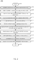
- FIG. 2 illustrates a flowchart of an example method 200 for deploying an application in a data center.
- the method 200 may be performed by an application server such as the AS 104 illustrated in FIG. 1 .
- the method 200 may be performed by another device.
- any references in the discussion of the method 200 to the AS 104 of FIG. 1 are not intended to limit the means by which the method 200 may be performed.
- an abstraction layer which sits on top of all deployment environments serves as an entry point to the method 200 .
- the abstraction layer ensures that all information required for configuration and deployment of the application has been obtained, that the devices requires to carry out the configuration and deployment are in sync with this information, that the devices are configured in the correct order, and that the final configuration is valid (i.e., will enable deployment of the application as intended).
- the method 200 begins in step 202 .
- a set of characteristics pertaining to the application to be deployed are identified. For instance, a human operator may supply the characteristics (e.g., via manual input) to an application that will generate a workflow for the deployment process. As such, the characteristics may be extracted from an electronic signal.
- the application characteristics include one or more of the following: virtual Internet Protocol (VIP) hostname (e.g., hostname(s) used to reach the VIP address over a domain name server), pool name (e.g., a load balancer parameter that tracks the physical and virtual resources allocated to a VIP), VIP type (e.g., a load balancer parameter tracking the type of VIP being configured), VIP address/port (e.g., a load balancer parameter that associates the VIP to the actual ports used), source (src) address (e.g., a firewall parameter that secures the entry point into the data center by defining the origin of the incoming data flow), protocol profile (e.g., a firewall parameter that tracks the protocols that need to be allowed into the data center), Hypertext Transfer Protocol (HTTP) profile (e.g., parameter used to set up world wide web access by the application), secure socket layer (SSL) profile (e.g., parameter used to track information required to secure sessions over the Internet), persistence profile (e.g., parameter used to ensure
- step 206 currently deployed instances of the application to be deployed are identified.
- the deployment type is the addition of a new application, there will be no currently deployed instances to be identified.
- the deployment type is either the upgrade of an existing application or the addition of resources to an existing application, there will be at least one currently deployed instance to be identified.
- a set of data center computing resources to be used in the deployment of the application are identified, located, and acquired.
- the resources may be physical, virtual, or a combination of the two.
- the deployment type is the upgrade of an existing application, there may be no resources to be identified, located, and acquired.
- the deployment type is either the addition of a new application or the addition of resources to an existing application, there will be resources to be identified, located, and acquired.
- a load balancer is automatically identified (e.g., without user guidance) for the deployment of the application.
- the particular load balancer to use may depend on one or both of the characteristics of the application and on the type of deployment. In one example, if the deployment type is the upgrade of an existing application or the addition of resources to an existing application, then the load balancer on which the existing application is deployed is selected for deployment of the upgrade or the addition of resources. In another example, if the deployment type is the addition of a new application, then an existing application to which the new application is most similar is identified, and the new application is deployed on the same load balancer as the most similar existing application.
- the load balancer that is most suited for the new application's characteristics (e.g., using virtualized resources versus physical resources, etc.) is selected got deployment of the new application.
- step 212 the resources that were identified, located, and acquired in step 208 are allocated to the application. This step may involve coordination with virtual machine hypervisors and/or human operators who may manually allocate all or some of the resources.
- IP address associated with the application is reserved. This step may involve coordination with DNS servers and/or IP address management (IPAM) tools.
- IP Internet Protocol
- step 216 the Virtual IP (VIP) address associated with the application is configured. This step may involve coordination with the load balancer(s) selected in step 210 .
- FIG. 3 illustrates one example of a method for configuring a selected load balancer, including configuration of the VIP address parameters, in more detail.
- step 218 the domain name server (DNS) VIP hostname associated with the application is updated.
- DNS domain name server
- step 220 the firewall(s) and intrusion detection system(s) (IDS) associated with the application are configured. This step may involve coordination with network security devices and/or network security applications.
- IDS intrusion detection system
- step 222 the global server load balancers associated with the application are configured. This step may involve coordination with global server load balancers.
- step 224 the configuration of the application is validated.
- the method 200 ends in step 226 .
- the allocation of computational resources may be performed at the same time that the load balancer is selected (e.g., as described in connection with step 210 ).
- FIG. 3 illustrates a flowchart of an example method 300 for configuring a load balancer for deployment of an application.
- the method 300 may be implemented, for example, in conjunction with step 216 of the method 200 .
- the method 200 may be performed by an application server such as the AS 104 illustrated in FIG. 1 .
- the method 300 may be performed by another device.
- any references in the discussion of the method 300 to the AS 104 of FIG. 1 are not intended to limit the means by which the method 300 may be performed.
- the method makes use of various application characteristics identified in step 204 of the method 200 .
- the method 300 begins in step 302 .
- the parameters of the application's VIP address are configured in coordination with the selected load balancer.
- the parameters to be configured include at least one of: VIP hostname, VIP type, or VIP Internet Protocol address (e.g., port).
- the parameters of the pool(s) associated with the load balancer is configured, along with the parameters of the physical server associated with the application.
- the pool parameters to be configured include at least the pool name(s).
- the parameters of the physical server include at least the source address.
- one or more health checks are performed.
- the health checks verify the availability and current health of the different resources deployed with the application, e.g., by checking one or more health monitors.
- nodes and members are created according to the application characteristics.
- the nodes and members are created using one or more of the following parameters associated with the application: protocol profile, HTTP profile, SSL profile, or persistence profile. In some cases, no nodes or members will be created depending on the application characteristics.
- one or more SNAT pools are configured, e.g., using one or more of the application characteristics identified in step 204 of the method 200 .
- IP address bindings are created between any nodes created in step 310 the physical server(s) associated with the application and the associated VIP addresses. Bindings may also be created between and the pools configured in step 306 and the physical servers. In one example, these bindings are created using the VIP address associated with the application. In a further example, load balancing methods and rules associated with the selected load balancer may also be involved in the creation of the bindings.
- the method 300 ends in step 316 .
- one or more steps of the methods 200 or 300 may include a storing, displaying and/or outputting step as required for a particular application.
- any data, records, fields, and/or intermediate results discussed in the method can be stored, displayed and/or outputted to another device as required for a particular application.
- operations, steps, or blocks of the above described method(s) can be combined, separated, and/or performed in a different order from that described above, without departing from the examples of the present disclosure.
- FIG. 4 depicts a high-level block diagram of a computing device specifically programmed to perform the functions described herein.
- any one or more components or devices illustrated in FIG. 1 or described in connection with the methods 200 or 300 may be implemented as the system 400 .
- an application server (such as might be used to perform the methods 200 or 300 ) could be implemented as illustrated in FIG. 4 .
- the system 400 comprises a hardware processor element 402 , a memory 404 , a module 405 for generating a workflow for application deployment, and various input/output (I/O) devices 406 .
- the hardware processor 402 may comprise, for example, a microprocessor, a central processing unit (CPU), or the like.
- the memory 404 may comprise, for example, random access memory (RAM), read only memory (ROM), a disk drive, an optical drive, a magnetic drive, and/or a Universal Serial Bus (USB) drive.
- the module 405 for generating a workflow for application deployment may include circuitry and/or logic for performing special purpose functions relating to the deploying an application in a physical and/or virtual data center.
- the input/output devices 406 may include, for example, storage devices (including but not limited to, a tape drive, a floppy drive, a hard disk drive or a compact disk drive), a receiver, a transmitter, a display, an output port, and/or a user input device (such as a keyboard, a keypad, a mouse, and the like).
- storage devices including but not limited to, a tape drive, a floppy drive, a hard disk drive or a compact disk drive
- a receiver a transmitter
- a display such as a keyboard, a keypad, a mouse, and the like
- a user input device such as a keyboard, a keypad, a mouse, and the like.
- the general-purpose computer may employ a plurality of processor elements.
- the general-purpose computer may employ a plurality of processor elements.
- the general-purpose computer of this Figure is intended to represent each of those multiple general-purpose computers.
- one or more hardware processors can be utilized in supporting a virtualized or shared computing environment.
- the virtualized computing environment may support one or more virtual machines representing computers, servers, or other computing devices. In such virtualized virtual machines, hardware components such as hardware processors and computer-readable storage devices may be virtualized or logically represented.
- the present disclosure can be implemented in software and/or in a combination of software and hardware, e.g., using application specific integrated circuits (ASIC), a programmable logic array (PLA), including a field-programmable gate array (FPGA), or a state machine deployed on a hardware device, a general purpose computer or any other hardware equivalents, e.g., computer readable instructions pertaining to the method(s) discussed above can be used to configure a hardware processor to perform the steps, functions and/or operations of the above disclosed method(s).
- ASIC application specific integrated circuits
- PDA programmable logic array
- FPGA field-programmable gate array
- instructions and data for the present module or process 405 for generating a workflow for application deployment can be loaded into memory 404 and executed by hardware processor element 402 to implement the steps, functions or operations as discussed above in connection with the example methods 200 and 300 .
- a hardware processor executes instructions to perform “operations,” this could include the hardware processor performing the operations directly and/or facilitating, directing, or cooperating with another hardware device or component (e.g., a co-processor and the like) to perform the operations.
- the processor executing the computer readable or software instructions relating to the above described method(s) can be perceived as a programmed processor or a specialized processor.
- the present module 405 for generating a workflow for application deployment (including associated data structures) of the present disclosure can be stored on a tangible or physical (broadly non-transitory) computer-readable storage device or medium, e.g., volatile memory, non-volatile memory, ROM memory, RAM memory, magnetic or optical drive, device or diskette and the like.
- the computer-readable storage device may comprise any physical devices that provide the ability to store information such as data and/or instructions to be accessed by a processor or a computing device such as a computer or an application server.
Abstract
Description
Claims (20)
Priority Applications (2)
| Application Number | Priority Date | Filing Date | Title |
|---|---|---|---|
| US15/455,919 US10834176B2 (en) | 2017-03-10 | 2017-03-10 | Automated end-to-end application deployment in a data center |
| US17/092,962 US11297128B2 (en) | 2017-03-10 | 2020-11-09 | Automated end-to-end application deployment in a data center |
Applications Claiming Priority (1)
| Application Number | Priority Date | Filing Date | Title |
|---|---|---|---|
| US15/455,919 US10834176B2 (en) | 2017-03-10 | 2017-03-10 | Automated end-to-end application deployment in a data center |
Related Child Applications (1)
| Application Number | Title | Priority Date | Filing Date |
|---|---|---|---|
| US17/092,962 Continuation US11297128B2 (en) | 2017-03-10 | 2020-11-09 | Automated end-to-end application deployment in a data center |
Publications (2)
| Publication Number | Publication Date |
|---|---|
| US20180262559A1 US20180262559A1 (en) | 2018-09-13 |
| US10834176B2 true US10834176B2 (en) | 2020-11-10 |
Family
ID=63445270
Family Applications (2)
| Application Number | Title | Priority Date | Filing Date |
|---|---|---|---|
| US15/455,919 Active 2037-06-14 US10834176B2 (en) | 2017-03-10 | 2017-03-10 | Automated end-to-end application deployment in a data center |
| US17/092,962 Active US11297128B2 (en) | 2017-03-10 | 2020-11-09 | Automated end-to-end application deployment in a data center |
Family Applications After (1)
| Application Number | Title | Priority Date | Filing Date |
|---|---|---|---|
| US17/092,962 Active US11297128B2 (en) | 2017-03-10 | 2020-11-09 | Automated end-to-end application deployment in a data center |
Country Status (1)
| Country | Link |
|---|---|
| US (2) | US10834176B2 (en) |
Cited By (1)
| Publication number | Priority date | Publication date | Assignee | Title |
|---|---|---|---|---|
| US11297128B2 (en) | 2017-03-10 | 2022-04-05 | Directv, Llc | Automated end-to-end application deployment in a data center |
Families Citing this family (4)
| Publication number | Priority date | Publication date | Assignee | Title |
|---|---|---|---|---|
| US10791103B2 (en) * | 2016-10-28 | 2020-09-29 | Vmware, Inc. | Adapting remote display protocols to remote applications |
| CN108769271A (en) * | 2018-08-20 | 2018-11-06 | 北京百度网讯科技有限公司 | Method, apparatus, storage medium and the terminal device of load balancing |
| CN109743754B (en) * | 2019-03-22 | 2021-05-28 | 北京邮电大学 | Communication method, communication device, electronic equipment and computer-readable storage medium |
| US20230048653A1 (en) * | 2021-07-29 | 2023-02-16 | Kyndryl, Inc. | Software application deployment |
Citations (31)
| Publication number | Priority date | Publication date | Assignee | Title |
|---|---|---|---|---|
| US20030046396A1 (en) | 2000-03-03 | 2003-03-06 | Richter Roger K. | Systems and methods for managing resource utilization in information management environments |
| CA2470300A1 (en) | 2003-06-30 | 2004-12-30 | Microsoft Corporation | Network load balancing with host status information |
| US20050149940A1 (en) | 2003-12-31 | 2005-07-07 | Sychron Inc. | System Providing Methodology for Policy-Based Resource Allocation |
| US7124101B1 (en) | 1999-11-22 | 2006-10-17 | Accenture Llp | Asset tracking in a network-based supply chain environment |
| US20070208844A1 (en) | 2004-09-13 | 2007-09-06 | Fujitsu Siemens Computers, Inc. | Computer Arrangement and Method for Providing Services for Clients Over a Network |
| US7509369B1 (en) | 2001-07-11 | 2009-03-24 | Swsoft Holdings, Ltd. | Balancing shared servers in virtual environments |
| US20100228819A1 (en) * | 2009-03-05 | 2010-09-09 | Yottaa Inc | System and method for performance acceleration, data protection, disaster recovery and on-demand scaling of computer applications |
| US7941556B2 (en) | 2005-02-23 | 2011-05-10 | At&T Intellectual Property I, Lp | Monitoring for replica placement and request distribution |
| US8140624B2 (en) | 2005-12-01 | 2012-03-20 | Computer Associates Think, Inc. | Automated deployment and configuration of applications in an autonomically controlled distributed computing system |
| CN102404378A (en) | 2010-09-07 | 2012-04-04 | 成都索贝数码科技股份有限公司 | Streaming media distribution and transmission network system |
| US8156199B1 (en) | 2006-11-10 | 2012-04-10 | Juniper Networks, Inc. | Centralized control of client-side domain name resolution using VPN services |
| US20120117241A1 (en) * | 2010-11-05 | 2012-05-10 | Verizon Patent And Licensing Inc. | Server clustering in a computing-on-demand system |
| US8296434B1 (en) | 2009-05-28 | 2012-10-23 | Amazon Technologies, Inc. | Providing dynamically scaling computing load balancing |
| US8756298B2 (en) | 2005-12-21 | 2014-06-17 | Cisco Technology, Inc. | System for automatic configuration of computers in a server farm |
| US8782206B2 (en) | 2008-08-27 | 2014-07-15 | Siemens Aktiengesellschaft | Load-balanced allocation of medical task flows to servers of a server farm |
| US8793348B2 (en) | 2009-09-18 | 2014-07-29 | Group Business Software Ag | Process for installing software application and platform operating system |
| CN104301415A (en) | 2014-10-21 | 2015-01-21 | 无锡云捷科技有限公司 | Global load balancing method based on HTTP redirection |
| US20150169291A1 (en) * | 2013-12-16 | 2015-06-18 | International Business Machines Corporation | Systems and methods for scaling a cloud infrastructure |
| US9154549B2 (en) | 2011-10-27 | 2015-10-06 | Cisco Technology, Inc. | Dynamic server farms |
| US20150341428A1 (en) * | 2014-05-20 | 2015-11-26 | Citrix Systems, Inc. | Systems and methods for providing load balancing as a service |
| US20150378703A1 (en) * | 2014-06-26 | 2015-12-31 | Vmware, Inc. | Application blueprints based on service templates to deploy applications in different cloud environments |
| US9235491B2 (en) | 2012-09-28 | 2016-01-12 | Wal-Mart Stores, Inc. | Systems and methods for installing, managing, and provisioning applications |
| US9270745B2 (en) | 2009-04-15 | 2016-02-23 | Accenture Global Services Limited | Method and system for client-side scaling of web server farm architectures in a cloud data center |
| US20160196124A1 (en) | 2015-01-06 | 2016-07-07 | Oracle International Corporation | Incremental provisioning of cloud-based modules |
| US9454406B2 (en) | 2011-02-28 | 2016-09-27 | Novell, Inc. | Techniques for cloud bursting |
| US9483258B1 (en) | 2011-04-27 | 2016-11-01 | Intuit Inc | Multi-site provisioning of resources to software offerings using infrastructure slices |
| US20160323187A1 (en) * | 2015-04-30 | 2016-11-03 | Amazon Technologies, Inc. | Managing load balancers associated with auto-scaling groups |
| WO2017004081A1 (en) | 2015-06-29 | 2017-01-05 | Genesys Telecommunications Laboratories, Inc. | System and method for intelligent task management and routing |
| US20170013049A1 (en) * | 2015-07-10 | 2017-01-12 | Brocade Communications Systems, Inc. | Intelligent Load Balancer Selection In A Multi-Load Balancer Environment |
| US20170048148A1 (en) | 2014-04-28 | 2017-02-16 | Huawei Technologies Co., Ltd. | Method, apparatus, and system for load balancing of service chain |
| US20180157542A1 (en) * | 2016-12-07 | 2018-06-07 | Vmware, Inc. | Methods and apparatus for event-based extensibility of system logic |
Family Cites Families (2)
| Publication number | Priority date | Publication date | Assignee | Title |
|---|---|---|---|---|
| US10291513B2 (en) * | 2015-11-30 | 2019-05-14 | At&T Intellectual Property I, L.P. | Topology aware load balancing engine |
| US10834176B2 (en) | 2017-03-10 | 2020-11-10 | The Directv Group, Inc. | Automated end-to-end application deployment in a data center |
-
2017
- 2017-03-10 US US15/455,919 patent/US10834176B2/en active Active
-
2020
- 2020-11-09 US US17/092,962 patent/US11297128B2/en active Active
Patent Citations (31)
| Publication number | Priority date | Publication date | Assignee | Title |
|---|---|---|---|---|
| US7124101B1 (en) | 1999-11-22 | 2006-10-17 | Accenture Llp | Asset tracking in a network-based supply chain environment |
| US20030046396A1 (en) | 2000-03-03 | 2003-03-06 | Richter Roger K. | Systems and methods for managing resource utilization in information management environments |
| US7509369B1 (en) | 2001-07-11 | 2009-03-24 | Swsoft Holdings, Ltd. | Balancing shared servers in virtual environments |
| CA2470300A1 (en) | 2003-06-30 | 2004-12-30 | Microsoft Corporation | Network load balancing with host status information |
| US20050149940A1 (en) | 2003-12-31 | 2005-07-07 | Sychron Inc. | System Providing Methodology for Policy-Based Resource Allocation |
| US20070208844A1 (en) | 2004-09-13 | 2007-09-06 | Fujitsu Siemens Computers, Inc. | Computer Arrangement and Method for Providing Services for Clients Over a Network |
| US7941556B2 (en) | 2005-02-23 | 2011-05-10 | At&T Intellectual Property I, Lp | Monitoring for replica placement and request distribution |
| US8140624B2 (en) | 2005-12-01 | 2012-03-20 | Computer Associates Think, Inc. | Automated deployment and configuration of applications in an autonomically controlled distributed computing system |
| US8756298B2 (en) | 2005-12-21 | 2014-06-17 | Cisco Technology, Inc. | System for automatic configuration of computers in a server farm |
| US8156199B1 (en) | 2006-11-10 | 2012-04-10 | Juniper Networks, Inc. | Centralized control of client-side domain name resolution using VPN services |
| US8782206B2 (en) | 2008-08-27 | 2014-07-15 | Siemens Aktiengesellschaft | Load-balanced allocation of medical task flows to servers of a server farm |
| US20100228819A1 (en) * | 2009-03-05 | 2010-09-09 | Yottaa Inc | System and method for performance acceleration, data protection, disaster recovery and on-demand scaling of computer applications |
| US9270745B2 (en) | 2009-04-15 | 2016-02-23 | Accenture Global Services Limited | Method and system for client-side scaling of web server farm architectures in a cloud data center |
| US8296434B1 (en) | 2009-05-28 | 2012-10-23 | Amazon Technologies, Inc. | Providing dynamically scaling computing load balancing |
| US8793348B2 (en) | 2009-09-18 | 2014-07-29 | Group Business Software Ag | Process for installing software application and platform operating system |
| CN102404378A (en) | 2010-09-07 | 2012-04-04 | 成都索贝数码科技股份有限公司 | Streaming media distribution and transmission network system |
| US20120117241A1 (en) * | 2010-11-05 | 2012-05-10 | Verizon Patent And Licensing Inc. | Server clustering in a computing-on-demand system |
| US9454406B2 (en) | 2011-02-28 | 2016-09-27 | Novell, Inc. | Techniques for cloud bursting |
| US9483258B1 (en) | 2011-04-27 | 2016-11-01 | Intuit Inc | Multi-site provisioning of resources to software offerings using infrastructure slices |
| US9154549B2 (en) | 2011-10-27 | 2015-10-06 | Cisco Technology, Inc. | Dynamic server farms |
| US9235491B2 (en) | 2012-09-28 | 2016-01-12 | Wal-Mart Stores, Inc. | Systems and methods for installing, managing, and provisioning applications |
| US20150169291A1 (en) * | 2013-12-16 | 2015-06-18 | International Business Machines Corporation | Systems and methods for scaling a cloud infrastructure |
| US20170048148A1 (en) | 2014-04-28 | 2017-02-16 | Huawei Technologies Co., Ltd. | Method, apparatus, and system for load balancing of service chain |
| US20150341428A1 (en) * | 2014-05-20 | 2015-11-26 | Citrix Systems, Inc. | Systems and methods for providing load balancing as a service |
| US20150378703A1 (en) * | 2014-06-26 | 2015-12-31 | Vmware, Inc. | Application blueprints based on service templates to deploy applications in different cloud environments |
| CN104301415A (en) | 2014-10-21 | 2015-01-21 | 无锡云捷科技有限公司 | Global load balancing method based on HTTP redirection |
| US20160196124A1 (en) | 2015-01-06 | 2016-07-07 | Oracle International Corporation | Incremental provisioning of cloud-based modules |
| US20160323187A1 (en) * | 2015-04-30 | 2016-11-03 | Amazon Technologies, Inc. | Managing load balancers associated with auto-scaling groups |
| WO2017004081A1 (en) | 2015-06-29 | 2017-01-05 | Genesys Telecommunications Laboratories, Inc. | System and method for intelligent task management and routing |
| US20170013049A1 (en) * | 2015-07-10 | 2017-01-12 | Brocade Communications Systems, Inc. | Intelligent Load Balancer Selection In A Multi-Load Balancer Environment |
| US20180157542A1 (en) * | 2016-12-07 | 2018-06-07 | Vmware, Inc. | Methods and apparatus for event-based extensibility of system logic |
Non-Patent Citations (5)
| Title |
|---|
| "Google Cloud Load Balancing," Google, cloud.google.com, Jul. 25, 2016. http://web.archive.org/web/20160725235836/https://cloud.google.com/loadbalancing/. |
| Gengbin Zheng et al., "Runtime Systems & Tools: Dynamic Load Balancing," Parallel Program Laboratory, warm.cs.uiuc.edu, University of Illinois, Nov. 3, 2012. http://web.archive.org/web/20121103115431/http://charm.cs.uiuc.edu/research/ldbal. |
| Mayanka Katyal et al., "A comparative study of load balancing algorithms in cloud computing environment." arXiv preprint arXiv:1403.6918 (Dec. 2013). https://arxiv.org/ftp/arxiv/papers/1403/1403.6918.pdf. |
| Tim Dornemann et al., "On-demand resource provisioning for BPEL workflows using Amazon's elastic compute cloud." Cluster Computing and the Grid, 2009. CCGRID'09. 9th IEEE/ACM International Symposium on. IEEE, May 18, 2009. http://citeseerx.ist.psu.edu/viewdoc/download?doi=10.1.1.151.1729&rep=rep1&type=pdf. |
| Vincent C. Emeakaroha et al., "SLA-aware application deployment and resource allocation in clouds." Computer Software and Applications Conference Workshops (COMPSACW), 2011 IEEE 35th Annual. IEEE, Jul. 18, 2011. http://hydra.infosys.tuwien.ac.at/staff/vincent/pub/Emeakaroha_CloudApp2011.pdf. |
Cited By (1)
| Publication number | Priority date | Publication date | Assignee | Title |
|---|---|---|---|---|
| US11297128B2 (en) | 2017-03-10 | 2022-04-05 | Directv, Llc | Automated end-to-end application deployment in a data center |
Also Published As
| Publication number | Publication date |
|---|---|
| US20180262559A1 (en) | 2018-09-13 |
| US11297128B2 (en) | 2022-04-05 |
| US20210058454A1 (en) | 2021-02-25 |
Similar Documents
| Publication | Publication Date | Title |
|---|---|---|
| US11297128B2 (en) | Automated end-to-end application deployment in a data center | |
| US11409550B2 (en) | Low latency connections to workspaces in a cloud computing environment | |
| US10362032B2 (en) | Providing devices as a service | |
| US10075459B1 (en) | Securing workspaces in a cloud computing environment | |
| EP3130132B1 (en) | Relay proxy providing secure connectivity in a controlled network environment | |
| US11012408B2 (en) | Configuring virtual machine instances using one-to-one mappings | |
| US11171809B2 (en) | Identity-based virtual private network tunneling | |
| US20140344459A1 (en) | Methods and systems for creating and managing network groups | |
| US9112880B2 (en) | Method and system for implementing integrated voice over internet protocol in a cloud-based network | |
| US9503392B2 (en) | Enhance private cloud system provisioning security | |
| US20190098107A1 (en) | Geographic location based user computing asset provisioning in distributed computing systems | |
| US20180248952A1 (en) | Protocol independent storage discovery and enablement | |
| US11405412B2 (en) | Inline anomaly detection for multi-request operations | |
| US11463426B1 (en) | Vaultless authentication | |
| US20240098073A1 (en) | Connectivity for virtual private label clouds | |
| US20220311735A1 (en) | Carrier grade network address translation architecture and implementation |
Legal Events
| Date | Code | Title | Description |
|---|---|---|---|
| AS | Assignment |
Owner name: THE DIRECTV GROUP, INC., CALIFORNIA Free format text: ASSIGNMENT OF ASSIGNORS INTEREST;ASSIGNORS:ARYA, VISHAL;CUGNO, CHRISTOPHER JOSEPH;OSMAN, SHARIQ;AND OTHERS;SIGNING DATES FROM 20170227 TO 20170307;REEL/FRAME:041548/0920 |
|
| STPP | Information on status: patent application and granting procedure in general |
Free format text: FINAL REJECTION MAILED |
|
| STPP | Information on status: patent application and granting procedure in general |
Free format text: DOCKETED NEW CASE - READY FOR EXAMINATION |
|
| STPP | Information on status: patent application and granting procedure in general |
Free format text: NON FINAL ACTION MAILED |
|
| STPP | Information on status: patent application and granting procedure in general |
Free format text: RESPONSE TO NON-FINAL OFFICE ACTION ENTERED AND FORWARDED TO EXAMINER |
|
| STPP | Information on status: patent application and granting procedure in general |
Free format text: FINAL REJECTION MAILED |
|
| STPP | Information on status: patent application and granting procedure in general |
Free format text: DOCKETED NEW CASE - READY FOR EXAMINATION |
|
| STPP | Information on status: patent application and granting procedure in general |
Free format text: PUBLICATIONS -- ISSUE FEE PAYMENT VERIFIED |
|
| STCF | Information on status: patent grant |
Free format text: PATENTED CASE |
|
| AS | Assignment |
Owner name: DIRECTV, LLC, CALIFORNIA Free format text: ASSIGNMENT OF ASSIGNORS INTEREST;ASSIGNOR:THE DIRECTV GROUP, INC.;REEL/FRAME:057143/0641 Effective date: 20210728 |
|
| AS | Assignment |
Owner name: CREDIT SUISSE AG, CAYMAN ISLANDS BRANCH, AS COLLATERAL AGENT, NEW YORK Free format text: SECURITY AGREEMENT;ASSIGNOR:DIRECTV, LLC;REEL/FRAME:057695/0084 Effective date: 20210802 |
|
| AS | Assignment |
Owner name: THE BANK OF NEW YORK MELLON TRUST COMPANY, N.A. AS COLLATERAL AGENT, TEXAS Free format text: SECURITY AGREEMENT;ASSIGNOR:DIRECTV, LLC;REEL/FRAME:058220/0531 Effective date: 20210802 |
|
| AS | Assignment |
Owner name: THE BANK OF NEW YORK MELLON TRUST COMPANY, N.A., AS COLLATERAL AGENT, TEXAS Free format text: SECURITY AGREEMENT;ASSIGNOR:DIRECTV, LLC;REEL/FRAME:066371/0690 Effective date: 20240124 |