US10833451B2 - Electrical connector - Google Patents
Electrical connector Download PDFInfo
- Publication number
- US10833451B2 US10833451B2 US16/601,543 US201916601543A US10833451B2 US 10833451 B2 US10833451 B2 US 10833451B2 US 201916601543 A US201916601543 A US 201916601543A US 10833451 B2 US10833451 B2 US 10833451B2
- Authority
- US
- United States
- Prior art keywords
- plug
- receptacle
- annular
- electrical contacts
- electrical
- Prior art date
- Legal status (The legal status is an assumption and is not a legal conclusion. Google has not performed a legal analysis and makes no representation as to the accuracy of the status listed.)
- Active
Links
Images


Classifications
-
- H—ELECTRICITY
- H01—ELECTRIC ELEMENTS
- H01R—ELECTRICALLY-CONDUCTIVE CONNECTIONS; STRUCTURAL ASSOCIATIONS OF A PLURALITY OF MUTUALLY-INSULATED ELECTRICAL CONNECTING ELEMENTS; COUPLING DEVICES; CURRENT COLLECTORS
- H01R13/00—Details of coupling devices of the kinds covered by groups H01R12/70 or H01R24/00 - H01R33/00
- H01R13/62—Means for facilitating engagement or disengagement of coupling parts or for holding them in engagement
- H01R13/627—Snap or like fastening
- H01R13/6275—Latching arms not integral with the housing
-
- A—HUMAN NECESSITIES
- A61—MEDICAL OR VETERINARY SCIENCE; HYGIENE
- A61N—ELECTROTHERAPY; MAGNETOTHERAPY; RADIATION THERAPY; ULTRASOUND THERAPY
- A61N1/00—Electrotherapy; Circuits therefor
- A61N1/18—Applying electric currents by contact electrodes
- A61N1/32—Applying electric currents by contact electrodes alternating or intermittent currents
- A61N1/36—Applying electric currents by contact electrodes alternating or intermittent currents for stimulation
- A61N1/362—Heart stimulators
- A61N1/3625—External stimulators
-
- A—HUMAN NECESSITIES
- A61—MEDICAL OR VETERINARY SCIENCE; HYGIENE
- A61N—ELECTROTHERAPY; MAGNETOTHERAPY; RADIATION THERAPY; ULTRASOUND THERAPY
- A61N1/00—Electrotherapy; Circuits therefor
- A61N1/18—Applying electric currents by contact electrodes
- A61N1/32—Applying electric currents by contact electrodes alternating or intermittent currents
- A61N1/36—Applying electric currents by contact electrodes alternating or intermittent currents for stimulation
- A61N1/372—Arrangements in connection with the implantation of stimulators
- A61N1/378—Electrical supply
- A61N1/3787—Electrical supply from an external energy source
-
- H—ELECTRICITY
- H01—ELECTRIC ELEMENTS
- H01R—ELECTRICALLY-CONDUCTIVE CONNECTIONS; STRUCTURAL ASSOCIATIONS OF A PLURALITY OF MUTUALLY-INSULATED ELECTRICAL CONNECTING ELEMENTS; COUPLING DEVICES; CURRENT COLLECTORS
- H01R13/00—Details of coupling devices of the kinds covered by groups H01R12/70 or H01R24/00 - H01R33/00
- H01R13/02—Contact members
- H01R13/04—Pins or blades for co-operation with sockets
- H01R13/08—Resiliently-mounted rigid pins or blades
-
- H—ELECTRICITY
- H01—ELECTRIC ELEMENTS
- H01R—ELECTRICALLY-CONDUCTIVE CONNECTIONS; STRUCTURAL ASSOCIATIONS OF A PLURALITY OF MUTUALLY-INSULATED ELECTRICAL CONNECTING ELEMENTS; COUPLING DEVICES; CURRENT COLLECTORS
- H01R13/00—Details of coupling devices of the kinds covered by groups H01R12/70 or H01R24/00 - H01R33/00
- H01R13/02—Contact members
- H01R13/10—Sockets for co-operation with pins or blades
- H01R13/11—Resilient sockets
- H01R13/111—Resilient sockets co-operating with pins having a circular transverse section
-
- H—ELECTRICITY
- H01—ELECTRIC ELEMENTS
- H01R—ELECTRICALLY-CONDUCTIVE CONNECTIONS; STRUCTURAL ASSOCIATIONS OF A PLURALITY OF MUTUALLY-INSULATED ELECTRICAL CONNECTING ELEMENTS; COUPLING DEVICES; CURRENT COLLECTORS
- H01R13/00—Details of coupling devices of the kinds covered by groups H01R12/70 or H01R24/00 - H01R33/00
- H01R13/02—Contact members
- H01R13/15—Pins, blades or sockets having separate spring member for producing or increasing contact pressure
- H01R13/187—Pins, blades or sockets having separate spring member for producing or increasing contact pressure with spring member in the socket
-
- H—ELECTRICITY
- H01—ELECTRIC ELEMENTS
- H01R—ELECTRICALLY-CONDUCTIVE CONNECTIONS; STRUCTURAL ASSOCIATIONS OF A PLURALITY OF MUTUALLY-INSULATED ELECTRICAL CONNECTING ELEMENTS; COUPLING DEVICES; CURRENT COLLECTORS
- H01R13/00—Details of coupling devices of the kinds covered by groups H01R12/70 or H01R24/00 - H01R33/00
- H01R13/02—Contact members
- H01R13/20—Pins, blades, or sockets shaped, or provided with separate member, to retain co-operating parts together
-
- H—ELECTRICITY
- H01—ELECTRIC ELEMENTS
- H01R—ELECTRICALLY-CONDUCTIVE CONNECTIONS; STRUCTURAL ASSOCIATIONS OF A PLURALITY OF MUTUALLY-INSULATED ELECTRICAL CONNECTING ELEMENTS; COUPLING DEVICES; CURRENT COLLECTORS
- H01R13/00—Details of coupling devices of the kinds covered by groups H01R12/70 or H01R24/00 - H01R33/00
- H01R13/44—Means for preventing access to live contacts
-
- H—ELECTRICITY
- H01—ELECTRIC ELEMENTS
- H01R—ELECTRICALLY-CONDUCTIVE CONNECTIONS; STRUCTURAL ASSOCIATIONS OF A PLURALITY OF MUTUALLY-INSULATED ELECTRICAL CONNECTING ELEMENTS; COUPLING DEVICES; CURRENT COLLECTORS
- H01R13/00—Details of coupling devices of the kinds covered by groups H01R12/70 or H01R24/00 - H01R33/00
- H01R13/62—Means for facilitating engagement or disengagement of coupling parts or for holding them in engagement
- H01R13/627—Snap or like fastening
- H01R13/6271—Latching means integral with the housing
- H01R13/6272—Latching means integral with the housing comprising a single latching arm
-
- H—ELECTRICITY
- H01—ELECTRIC ELEMENTS
- H01R—ELECTRICALLY-CONDUCTIVE CONNECTIONS; STRUCTURAL ASSOCIATIONS OF A PLURALITY OF MUTUALLY-INSULATED ELECTRICAL CONNECTING ELEMENTS; COUPLING DEVICES; CURRENT COLLECTORS
- H01R13/00—Details of coupling devices of the kinds covered by groups H01R12/70 or H01R24/00 - H01R33/00
- H01R13/62—Means for facilitating engagement or disengagement of coupling parts or for holding them in engagement
- H01R13/629—Additional means for facilitating engagement or disengagement of coupling parts, e.g. aligning or guiding means, levers, gas pressure electrical locking indicators, manufacturing tolerances
- H01R13/633—Additional means for facilitating engagement or disengagement of coupling parts, e.g. aligning or guiding means, levers, gas pressure electrical locking indicators, manufacturing tolerances for disengagement only
- H01R13/635—Additional means for facilitating engagement or disengagement of coupling parts, e.g. aligning or guiding means, levers, gas pressure electrical locking indicators, manufacturing tolerances for disengagement only by mechanical pressure, e.g. spring force
-
- H—ELECTRICITY
- H01—ELECTRIC ELEMENTS
- H01R—ELECTRICALLY-CONDUCTIVE CONNECTIONS; STRUCTURAL ASSOCIATIONS OF A PLURALITY OF MUTUALLY-INSULATED ELECTRICAL CONNECTING ELEMENTS; COUPLING DEVICES; CURRENT COLLECTORS
- H01R13/00—Details of coupling devices of the kinds covered by groups H01R12/70 or H01R24/00 - H01R33/00
- H01R13/64—Means for preventing incorrect coupling
- H01R13/641—Means for preventing incorrect coupling by indicating incorrect coupling; by indicating correct or full engagement
-
- H—ELECTRICITY
- H01—ELECTRIC ELEMENTS
- H01R—ELECTRICALLY-CONDUCTIVE CONNECTIONS; STRUCTURAL ASSOCIATIONS OF A PLURALITY OF MUTUALLY-INSULATED ELECTRICAL CONNECTING ELEMENTS; COUPLING DEVICES; CURRENT COLLECTORS
- H01R13/00—Details of coupling devices of the kinds covered by groups H01R12/70 or H01R24/00 - H01R33/00
- H01R13/66—Structural association with built-in electrical component
- H01R13/70—Structural association with built-in electrical component with built-in switch
- H01R13/703—Structural association with built-in electrical component with built-in switch operated by engagement or disengagement of coupling parts, e.g. dual-continuity coupling part
-
- A—HUMAN NECESSITIES
- A61—MEDICAL OR VETERINARY SCIENCE; HYGIENE
- A61N—ELECTROTHERAPY; MAGNETOTHERAPY; RADIATION THERAPY; ULTRASOUND THERAPY
- A61N1/00—Electrotherapy; Circuits therefor
- A61N1/18—Applying electric currents by contact electrodes
- A61N1/32—Applying electric currents by contact electrodes alternating or intermittent currents
- A61N1/36—Applying electric currents by contact electrodes alternating or intermittent currents for stimulation
- A61N1/362—Heart stimulators
-
- H—ELECTRICITY
- H01—ELECTRIC ELEMENTS
- H01R—ELECTRICALLY-CONDUCTIVE CONNECTIONS; STRUCTURAL ASSOCIATIONS OF A PLURALITY OF MUTUALLY-INSULATED ELECTRICAL CONNECTING ELEMENTS; COUPLING DEVICES; CURRENT COLLECTORS
- H01R12/00—Structural associations of a plurality of mutually-insulated electrical connecting elements, specially adapted for printed circuits, e.g. printed circuit boards [PCB], flat or ribbon cables, or like generally planar structures, e.g. terminal strips, terminal blocks; Coupling devices specially adapted for printed circuits, flat or ribbon cables, or like generally planar structures; Terminals specially adapted for contact with, or insertion into, printed circuits, flat or ribbon cables, or like generally planar structures
- H01R12/50—Fixed connections
- H01R12/51—Fixed connections for rigid printed circuits or like structures
- H01R12/53—Fixed connections for rigid printed circuits or like structures connecting to cables except for flat or ribbon cables
-
- H—ELECTRICITY
- H01—ELECTRIC ELEMENTS
- H01R—ELECTRICALLY-CONDUCTIVE CONNECTIONS; STRUCTURAL ASSOCIATIONS OF A PLURALITY OF MUTUALLY-INSULATED ELECTRICAL CONNECTING ELEMENTS; COUPLING DEVICES; CURRENT COLLECTORS
- H01R2105/00—Three poles
-
- H—ELECTRICITY
- H01—ELECTRIC ELEMENTS
- H01R—ELECTRICALLY-CONDUCTIVE CONNECTIONS; STRUCTURAL ASSOCIATIONS OF A PLURALITY OF MUTUALLY-INSULATED ELECTRICAL CONNECTING ELEMENTS; COUPLING DEVICES; CURRENT COLLECTORS
- H01R2201/00—Connectors or connections adapted for particular applications
- H01R2201/12—Connectors or connections adapted for particular applications for medicine and surgery
-
- H—ELECTRICITY
- H01—ELECTRIC ELEMENTS
- H01R—ELECTRICALLY-CONDUCTIVE CONNECTIONS; STRUCTURAL ASSOCIATIONS OF A PLURALITY OF MUTUALLY-INSULATED ELECTRICAL CONNECTING ELEMENTS; COUPLING DEVICES; CURRENT COLLECTORS
- H01R24/00—Two-part coupling devices, or either of their cooperating parts, characterised by their overall structure
- H01R24/58—Contacts spaced along longitudinal axis of engagement
Definitions
- This disclosure generally relates to electrical systems, and more specifically relates to an electrical connector.
- a pacemaker typically includes a connector that allows connecting the electrodes in the heart to the pacemaker. Because a pacemaker is implanted inside a patient's body, the connector must be sealed so no bodily fluids can enter the pacemaker. Other medical devices may be implanted in a patient's body, but require electrical leads that pass outside the body that are connected to external medical equipment.
- TAH total artificial heart
- VAD ventricular assist device
- neurostimulators including transcutaneous electrical nerve stimulators (TENS), percutaneous electrical nerve stimulators (PENS), transcranial magnetic stimulation (TMS), and percutaneous cochlear implant systems (PCIS).
- Connectors for electrical leads that pass from a person's body to external equipment have different requirements than implantable connectors due to safety concerns.
- Known connectors for connecting external equipment to an implanted device suffer from various disadvantages.
- An electrical connector includes a plug that mates with a receptacle.
- the plug is connected to electrical leads that pass through a patient's skin to an implanted medical device in the patient's body, while the receptacle is connected to external medical equipment. All electrical contacts in the plug are on internal portions.
- the receptacle includes annular contacts that contact the internal electrical contacts on the plug when the plug and receptacle are properly mated.
- the receptacle includes a plurality of annular electrical contacts that have a first diameter and are separated by a plurality of annular insulators having a second diameter smaller than the first diameter.
- FIG. 1 illustrates a known connector used in a prior art pacemaker
- FIG. 2 illustrates a known connector used for connecting an implanted device to external medical equipment
- FIG. 3 illustrates one suitable implementation for an electrical connector within the scope of the claims and disclosure herein;
- FIG. 4 is a side view of the plug shown in FIG. 3 ;
- FIG. 5 is a cross-sectional view of the plug shown in FIGS. 3 and 4 showing its internal structure
- FIG. 6 is a perspective view of one specific implementation of a conductor ring shown in FIG. 5 ;
- FIG. 7 is a perspective view of one specific implementation of an insulator ring shown in FIG. 5 ;
- FIG. 8 is a partial side cutaway view of the receptacle shown in FIG. 3 ;
- FIG. 9 is an exploded view of the receptacle in FIGS. 3 and 8 showing its internal components
- FIG. 10 is a bottom cross-sectional view of the receptacle shown in FIG. 8 taken along the line 10 - 10 ;
- FIG. 11 is a perspective view of the contact assembly in the receptacle shown in FIGS. 8-10 ;
- FIG. 12 is an end view of the contact assembly in FIG. 11 in accordance with a first implementation
- FIG. 13 is an enlarged cross-sectional view of the contact assembly in FIGS. 11-12 showing the internal electrical contacts;
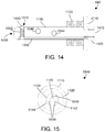
- FIG. 14 is a side cross-sectional view of the first implementation of the contact assembly shown in FIGS. 11-13 ;
- FIG. 15 is an end view of the contact assembly in FIG. 11 in accordance with a second implementation
- FIG. 16 is a side cross-sectional view of the second implementation of the contact assembly shown in FIG. 15 ;
- FIG. 17 is a side cross-sectional view showing the plug 340 mated to the contact assembly 840 of the receptacle to illustrate the electrical contacts;
- FIG. 18 is a block diagram of a circuit for detecting when the plug is mated to the receptacle
- FIG. 19 is a flow diagram of one suitable method for mating the plug to the receptacle
- FIG. 20 is a flow diagram of one suitable method for unmating the plug from the receptacle
- FIG. 21 is side cross-sectional view of a second implementation for a plug
- FIG. 22 is an exploded view of the plug in FIG. 21 showing its internal components
- FIG. 23 is a perspective view of a second implementation for a contact assembly in a receptacle
- FIG. 24 is a perspective cross-sectional view of the contact assembly in FIG. 23 ;
- FIG. 25 is a perspective view of a core portion of the contact assembly in FIG. 23 ;
- FIG. 26 is a perspective view of an annular contact ring used in the contact assembly in FIG. 23 ;
- FIG. 27 is a perspective view of a cylindrical insulator sleeve used in the contact assembly in FIG. 23 ;
- FIG. 28 is a perspective view showing how three annular contact rings are arranged in the contact assembly in FIG. 23 ;
- FIG. 29 is a side cross-sectional view of the contact assembly shown in FIGS. 23 and 24 ;
- FIG. 30 is a side cross-sectional view of a second implementation for the receptacle that includes the contact assembly shown in FIGS. 23, 24 and 29 ;
- FIG. 31 is a side cross-sectional view of the receptacle in FIG. 30 with the plug in FIGS. 21 and 22 plugged into the receptacle;
- FIG. 32 is a side cross-sectional view of a third implementation for the receptacle that includes the contact assembly shown in FIGS. 23, 24 and 29 ;
- FIG. 33 is a side cross-sectional view of the receptacle in FIG. 32 with the plug in FIG. 21 being inserted into the receptacle;
- FIG. 34 is a side cross-sectional view of the receptacle in FIGS. 32 and 33 with the plug fully seated into the receptacle;
- FIG. 35 is a side cross-sectional view of the plug and receptacle in FIG. 34 with a front portion of the receptacle slid towards the back section of the receptacle to disengage the retaining arms in the receptacle from the plug;
- FIG. 36 is a flow diagram of a method for removing the plug in FIGS. 34 and 35 from the receptacle.
- Implantable medical devices give rise to the need for specialized electrical connectors.
- a prior art pacemaker 110 is shown with a receptacle 120 that includes three electrical contacts 130 , which are electrically connected to the pacemaker circuitry, which is not shown in FIG. 1 .
- Electrodes that are designed for use with the pacemaker include a cable 140 that includes a plug 160 that includes three electrical contacts 170 .
- the plug 160 is inserted and properly mated to the receptacle 120 , the three electrical contacts 170 on the plug make electrical contact with the three electrical contacts 130 in the receptacle 120 , thereby connecting the electrodes to the circuitry in the pacemaker.
- Bal Conn connectors are suitable for use in pacemakers, such as the connector illustrated in FIG. 1 .
- Bal Conn is a registered trademark of Bal Seal Engineering, Inc.
- a plug that includes external contacts such as plug 160 in FIG. 1 is not suitable for connecting an implanted device to external equipment.
- International Electric Code 60601-1 specifies standards for medical equipment.
- Subclause 8.5.2.3 addresses patient leads or patient cables, and specifies there should be no possibility of connecting the patient accidentally to things that could deliver an electrical shock to the patient.
- a connector that has external contacts as shown in FIG. 1 could be placed in an electrical outlet, which would cause power to flow from the outlet through the exposed contacts 170 to the patient.
- the connector shown in FIG. 1 would therefore likely violate IEC 60601-1 Subclause 8.5.2.3 if it were used to connect an implanted device to external electrical equipment.
- Connectors that are used to attach implanted devices to external equipment thus have different requirements than connectors that do not have a connection outside the body.
- Examples of one known prior art connector that might be used to connect an implanted device to external equipment is shown at 210 in FIG. 2 .
- Specific examples of known connectors similar to the prior art connector 210 shown in FIG. 2 include the T-series IP 68 Push-Pull Connectors from Lemo USA, Inc., and the UltiMate connectors from Fischer Connectors SA.
- the prior art connector 210 shown in FIG. 2 includes a plug portion 220 connected to a cable 240 that mates to a receptacle portion 230 connected to a cable 250 .
- cable 240 is connected to an implanted device, and cable 250 is connected to external equipment.
- Connector 210 does not have exposed contacts like the pacemaker plug 160 shown in FIG. 1 , thereby reducing the shock hazard to a patient.
- the diameter D 1 of the plug 220 is substantially larger than the diameter D 2 of the cable 240 that attaches to the plug 220 . This means an incision must be made in the patient's skin that is large enough to accommodate the diameter D 1 of the plug 220 so the plug 220 can be passed from the implanted device inside the patient's body through the skin to the connector 230 that is connected to the external equipment.
- plug 220 and receptacle 230 typically include pins that require a specific orientation between plug 220 and receptacle 230 in order for the two to be connected.
- implanted connectors that have external contacts as shown in FIG. 1 are not suitable for use outside the body due to risk of shock.
- Known connectors such as shown in FIG. 2 can be used to connect an implanted device to external equipment, but these connectors require an incision that is significantly larger than the cable, creating a risk of infection at the site where the cable passes through the skin, and these connectors require a specific orientation to be mated together.
- the connector disclosed herein solves these problems.
- An electrical connector includes a plug that mates with a receptacle.
- the plug is connected to electrical leads that pass through a patient's skin to an implanted medical device in the patient's body, while the receptacle is connected to external medical equipment. All electrical contacts in the plug are on internal portions.
- the receptacle includes annular contacts that contact the internal electrical contacts on the plug when the plug and receptacle are properly mated.
- the receptacle includes a plurality of annular electrical contacts that have a first diameter and are separated by a plurality of annular insulators having a second diameter smaller than the first diameter.
- a connector 300 includes a plug 340 that mates to a receptacle 302 .
- the plug 340 is connected to a cable 350 , which is connected to an implanted medical device.
- a cable 320 that is connected on one end to external medical equipment is connected at the other end through a strain relief 330 to the receptacle 302 .
- the receptacle 302 includes a housing 310 , two opposed movable release buttons 370 for releasing the plug, and an opening 360 for receiving the plug 340 . Note that only one of the movable release buttons 370 is shown in FIG. 3 .
- FIG. 4 shows an enlarged side view of the plug 340 shown in FIG. 3 .
- Plug 340 includes a substantially rigid body portion 410 coupled to a flexible strain relief 420 .
- the body portion 410 includes an annular recess 430 that allows locking the plug 340 into place in the receptacle 302 .
- a cross-sectional view of the plug 340 in FIGS. 3 and 4 is shown in FIG. 5 to illustrate its internal structure.
- the body portion 410 includes a printed circuit board 540 that provides electrical connections between wires in the cable, which is not shown in FIG. 5 , and the electrical contacts 560 , 562 and 564 .
- the printed circuit board could be any suitable type of printed circuit board, whether currently known or developed in the future.
- a common type of known printed circuit board is a fiberglass-epoxy printed circuit board.
- the printed circuit board 540 also includes a post 542 for connecting a structural member of the cable, such as a reinforcing wire, to the printed circuit board.
- the electrical contacts 560 , 562 and 564 are separated by insulators 550 , 552 and 554 , and have an additional insulator 556 at the end. Each electrical contact 560 , 562 and 564 is electrically connected to a different contact point on the printed circuit board 540 .
- a wire 570 is shown in FIG. 5 that connects printed circuit board 540 to the electrical contact 564 .
- the wire 570 preferably includes insulation that is stripped from the ends so the ends can be electrically connected to the printed circuit board 540 and the electrical contact 564 .
- the stripped ends of wire 570 are soldered to the printed circuit board 540 and to the electrical contact 564 .
- any suitable electrical connection could be used within the scope of the disclosure and claims herein.
- the wires are drawn-filled tubes (DFTs), they cannot be soldered, but could be laser welded or mechanically crimped to the printed circuit board and to the respective electrical contact.
- electrical contacts 560 and 562 have corresponding wires that electrically connect these contacts to the printed circuit board 540 , even though these are not shown in FIG. 5 .
- Electrical contact 610 in FIG. 6 is one suitable implementation for the electrical contacts 560 , 562 and 564 shown in FIG. 5 .
- Electrical contact 610 includes a hollow circular interior portion 620 , two outside recesses 630 , and a connection point 640 .
- the two outside recesses 630 and connection point 640 are most preferably at 120 degree angles from each other, so the three are equally-spaced along the circumferences of the electrical contact 610 . Of course, these could be spaced at different angles as well.
- connection point 640 is the point where the wire is connected (e.g., soldered), such as shown at the bottom of electrical contact 564 in FIG. 5 .
- the outside recesses 630 allow wires for the other electrical contacts to pass.
- Each electrical contact 560 , 562 and 564 is rotated 120 degrees with respect to its neighbor so the contact point 640 of each aligns with the outside recesses 630 of the neighbor(s).
- the insulator 710 in FIG. 7 is one suitable implementation for the insulators 552 and 554 shown in FIG. 5 .
- the insulator 710 includes a hollow circular interior portion 720 and three outside recesses 730 .
- the outside recesses 730 provide a place for the wires to run that connect the printed circuit board 540 to the electrical contacts 560 , 562 and 564 .
- insulators 550 and 556 have slightly different dimensions and/or configurations than insulators 552 and 554 , they preferably include outside recesses similar to the outside recesses 730 shown in FIG. 7 .
- the inside portion of plug 340 can be manufactured as follows. Note the steps it the manufacturing process are provided by way of example, and any suitable steps or sequence could be used.
- the printed circuit board 540 is placed in a desired position. Three wires are soldered into the printed circuit board 540 into three holes that are most preferably 120 degrees apart near the perimeter of the printed circuit board.
- the insulator 550 is placed next to the printed circuit board so the three wires pass through the three outside recesses (see 730 in FIG. 7 ).
- the electrical contact 560 is placed next to insulator 550 , then connected to the correct one of the three wires at its contact point (see 640 in FIG. 6 ).
- the remaining two wires are placed in the outside recesses 630 of contact point 560 .
- the next insulator 552 is then placed next to the electrical contact 560 so the two remaining wires pass through two of the outside recesses.
- the electrical contact 562 is placed next to insulator 552 , then connected to the correct one of the two remaining wires at its contact point.
- the next insulator 554 is then placed next to the electrical contact 562 so the remaining one wire passes through one of the outside recesses.
- the electrical contact 564 is placed next to the insulator 554 , then soldered to the one remaining wire at its contact point.
- the next insulator 556 is then placed next to the electrical contact 564 . Note these pieces could be secured together using any suitable means.
- adhesive could be used to connect each piece to the next.
- structural attachments could be used, such as three small posts at 120 degree angles on each piece that fit into corresponding three small recesses on each piece when the two are properly aligned.
- the result is a stack that includes the printed circuit board 540 , insulator 550 , electrical contact 560 , insulator 552 , electrical contact 562 , insulator 554 , electrical contact 564 , and insulator 556 .
- a cable can then be run through the strain relief 420 and through the body portion 410 so the wires of the cable are exposed out the right end of the plug shown in FIGS. 4 and 5 .
- FIG. 5 shows an annular retaining ring 580 that is snapped into place to hold the internal stack in place.
- any suitable retaining member could be used.
- one or more plastic tabs could be provided so that once the stack is slid into place, the plastic tabs captivate the stack so it cannot move.
- one or more set screws could be used.
- the disclosure and claims herein extend to any suitable retaining member or mechanism. Note the sequence described above for assembling the plug can vary. For example, the cable could be inserted through the strain relief 420 and body portion 410 , and can be soldered or otherwise electrically connected to the printed circuit board 540 before the stack is created. The disclosure and claims herein expressly extend to any suitable sequence for assembling the plug 340 .
- FIG. 8 is a partial cutaway view showing some of the internal features of the receptacle 302 .
- the housing 310 provides a strain relief 330 through which a cable that is to be connected to some external equipment is run.
- the cable is not shown in FIG. 8 .
- the cable will have multiple wires that are connected to the contact assembly 840 , such as by soldering the wires to connections on a printed circuit board that is part of the contact assembly 840 .
- Two screws 810 are used to connect different pieces in the receptacle 302 together.
- a retention arm 820 is shown with its corresponding tip portion 822 that engages the annular recess 430 on the plug 340 when the plug 340 is properly mated to the receptacle 302 .
- An outer housing 830 has a substantially cylindrical shape, and surrounds most of the contact assembly 840 .
- a switch 850 is provided as one suitable form for a connection detection sensor. When the plug is within the receptacle, the switch is in one state, and when the plug is not within the receptacle, the switch is in an opposite state.
- the switch could be normally open when the plug is not within the receptacle, and when the plug is inserted into the receptacle, the plug actuates the switch 850 , thereby closing the switch and providing an indication that the plug is within the receptacle.
- the opening 360 of receptacle 302 is shown to include an O-ring 860 that seals around the body portion 410 of the plug 340 when the plug 340 is inserted into the opening 360 of receptacle 302 , to seal the junction between the plug 340 and the receptacle 302 to be fluid-tight.
- FIG. 9 shows an exploded view of the receptacle 302 shown in FIG. 8 .
- Strain relief 330 in FIG. 8 includes a rubber portion 918 coupled to a rigid portion 950 that is coupled via a washer 960 and nut 970 to the front face 914 of the receptacle 302 .
- the outer housing 830 and switch 850 described above with respect to FIG. 8 are shown in FIG. 9 .
- Two bushings 940 are spacers through which the screws 810 pass to connect the main housing 912 to the front face 914 .
- Front face 914 preferably includes two threaded holes 952 that receive the screws 810 to secure the front face 914 to the main housing 912 .
- the bottom bushing 940 passes through the two retention arms 820 and 824 , providing a common pivot point for the two retention arms 820 and 824 .
- a spring 930 is installed in recesses in the upper portions of the two retention arms 820 and 824 , and presses the two retention arms 820 and 824 apart, which causes the corresponding tip portions 822 and 826 to be biased in a closed position due to the scissor-like action of the two retention arms 820 and 824 . Due to spring 930 , the retention arms 820 and 824 , and their corresponding tip portions 822 and 826 , are spring-loaded. Tip portions 822 and 826 preferably include a substantially semicircular configuration so the two tip portions can lock into the annular recess in the plug.
- Two opposed movable release buttons 922 are installed into the main housing 912 , with pegs 920 that contact the top portions of the retention arms 820 and 824 .
- Release buttons 922 have two corresponding springs 926 that bias the release buttons 922 outward, so the release buttons 922 are biased in a non-depressed state, as shown at 370 in FIG. 3 .
- a peg 920 and spring 926 preferably are installed in corresponding recesses 924 in each release button 922 .
- a user can press the two opposed release buttons 922 simultaneously by pressing one with a thumb and the other with a finger, for example, which will cause the tops of the retention arms 820 and 824 to be pushed towards each other, which will cause the tip portions 822 and 826 to separate from each other, thereby disengaging the tip portions 822 and 826 from the annular recess in the plug.
- a person thus releases a plug that is locked into place in the receptacle by the tip portions 822 and 826 of the retention arms 820 and 824 by pressing simultaneously on the release buttons 922 , which disengages the tip portions 822 and 826 from the annular recess on the plug.
- a flexible polymer covering 910 is provided to encase and thereby protect the assembled receptacle 302 .
- FIG. 10 is a partial cross-sectional view of the receptacle 302 in FIG. 8 taken along the line 10 - 10 .
- the contact assembly 840 is shown, along with the strain relief 330 , and the opening 360 that includes the O-ring 860 .
- FIG. 10 shows in more detail that the tip portions 822 and 826 of the retention arms each have a beveled front.
- tip portion 822 includes a beveled front 1010
- tip portion 826 includes a beveled front 1012 .
- the plug when the plug contacts the beveled fronts 1010 and 1012 , the plug will slide along the beveled fronts 1010 and 1012 , thereby separating the tip portions 822 and 826 a sufficient distance for the plug to pass between the tip portions 822 and 826 .
- the retention arms have a spring that provides a bias force to keep the tip portions 822 and 826 together, the plug sliding along the beveled fronts 1010 and 1012 forces the tip portions 822 and 826 apart against the bias of the spring.
- the tip portions 822 and 826 When the plug is fully seated in the receptacle 302 , the tip portions 822 and 826 will engage the annular recess 430 shown in FIG. 4 , thereby locking the plug 340 in place.
- the plug can still be rotated in any direction while maintaining the electrical connections between the plug and the receptacle.
- no special keying or orientation is needed to mate the plug to the receptacle.
- the connection between the two is omnidirectional, meaning the plug can be in any suitable rotational relationship with respect to the receptacle.
- the contact assembly 840 preferably includes a printed circuit board 1110 , an ejection spring 1120 , and a cylindrical body 1130 that includes multiple spring-loaded electrical contacts 1140 , 1142 and 1144 .
- FIG. 12 is an end view of the contact assembly 840 shown in FIG. 11 .
- FIG. 13 is an enlarged cross-sectional view of the cylindrical body 1130 showing a spring assembly 1310 that has a ball head 1140 electrically coupled to a spring 1320 , which is electrically coupled to a base 1330 .
- the base 1330 of the spring assembly 1310 is electrically coupled to a wire 1340 , which is electrically coupled to the printed circuit board 1110 , which is connected to a cable that runs through the strain relief 330 into the receptacle 302 .
- the electrical conductors in the cable are made available via the spring-loaded ball contacts of the spring assemblies shown in FIG. 13 .
- Each spring assembly is placed in a corresponding cylindrical hole.
- spring assembly 1310 in FIG. 13 is placed within a corresponding cylindrical hole 1342 .
- the other two spring assemblies 1350 and 1360 are placed within their corresponding holes 1344 and 1346 , respectively, that are at a 120 degree angle with respect to hole 1350 , thereby providing evenly-spaced electrical contacts around the circumference of the cylindrical body 1130 .
- These other two spring assemblies 1350 and 1360 are shown in phantom in FIG. 13 for clarity.
- the specific example shown in the figures assumes three electrical contacts, which means each is at a 120 degree angle with respect to the other two. Note, however, the principles herein apply to any suitable number of electrical contacts, and any suitable spacing or arrangement. For example, if six electrical contacts are needed, there could be six different electrical contacts provided by six corresponding spring assemblies spaced in 60 degree increments.
- FIG. 14 is a cross-sectional view of the contact assembly 840 shown in FIGS. 11-13 .
- the ejection spring 1120 is shown as a flexible material having baffles that give, allowing the plug to partially compress the ejection spring 1120 to be seated correctly in the receptacle 302 .
- the ejection spring 1120 could have other configurations as well.
- the ejection spring 1120 could be a somewhat solid member, such as rubber or foam, that has the required resiliency to allow locking the plug into place in the receptacle.
- ejection spring 1120 could also be a metal spring.
- the ejection spring 1120 could be any suitable material and/or configuration that provides some linear resistance along the longitudinal axis of the cylindrical body 1130 such that when a plug first contacts the ejection spring 1120 , the plug is not fully seated inside the receptacle, but by pressing the plug into the receptacle with some additional force, the ejection spring is partially compressed until the tip portions of the retention arms lock into place in the annular recess of the plug, thereby retaining the plug in a mated position with respect to the receptacle.
- the retaining spring is preferably compressed less than 0.050 inch (1.3 mm) when the tip portions of the retention arms lock into place in the annular recess of the plug.
- the ejection spring thus serves two functions.
- the ejection spring serves to assure the plug is properly mated to the receptacle by requiring compression of the ejection spring in order for the receptacle to lock the plug into place.
- the ejection spring serves in the disconnection of the plug from the receptacle.
- the ejection spring moves the plug to a position where the tip portions of the retention arms do not engage the annular recess in the plug when the two release buttons are no longer pressed.
- a person disconnecting the plug can depress the two release buttons, which will cause the plug to disengage from the retention arms and to move out of position from being locked by the retention arms.
- the plug can then be pulled out of the receptacle without a need for pressing the two release buttons while the plug is pulled out.
- the plug can include a printed annular ring on the exterior that could provide a visual indication that the plug is correctly mated to the receptacle.
- the printed annular ring is located so that when the plug is properly mated with the receptacle, the printed annular ring is not visible.
- the printed annular ring is located so that when the plug is properly mated with the receptacle, the printed annular ring is next to the housing on the receptacle.
- Spring assembly 1310 in FIG. 14 is shown with a semi-spherical head 1440 instead of a spherical ball-shaped head 1140 shown in FIGS. 11-13 .
- the spring assemblies in the contact assembly provide a plurality of electrical contacts that contact the plurality of annular electrical contacts in the plug when the plug is mated to the receptacle.
- FIG. 14 shows a wire 1340 that is used to connect the spring assembly 1310 to the printed circuit board 1110 .
- the wire 1340 is soldered to the spring assembly 1310 and the printed circuit board 1110 .
- the wire 1340 could be laser-welded, crimped, or attached using some other means to the spring assembly 1310 and/or the printed circuit board 1110 .
- the cylindrical body 1130 is made of a rigid plastic material that is extruded through a die that provides three longitudinal cylindrical channels in which the wires can be placed.
- the holes for the spring assemblies such as holes 1342 , 1344 and 1346 are drilled at 120 degree angles with respect to each other at a location where each hole intersects one of the three longitudinal cylindrical channels in which wires can be placed.
- the spring assemblies are then dropped into their respective holes and attached to the corresponding wire at the bottom of the hole.
- Note the cylindrical body 1130 in FIG. 14 includes the other two holes 1346 and 1344 drilled at 120 degree angles with respect to hole 1342 , but the spring assemblies in these holes are not shown in FIG. 14 for the sake of clarity.
- the body portion 1130 preferably includes a rounded front 1430 as shown in FIG. 14 that eases the alignment of the plug onto the contact assembly 840 .
- the end of the cylindrical body 1130 that attaches to the printed circuit board 1110 may have a threaded portion 1410 that can receive a nut 1420 to attach the cylindrical body 1130 to the printed circuit board 1110 .
- the printed circuit board 1110 preferably includes features that allow attaching conductors from a cable that runs through the strain relief into the receptacle to the printed circuit board, such as a connector, solder pads, etc.
- a second specific implementation for the contact assembly 840 is shown as contact assembly 1540 in FIGS. 15 and 16 .
- Contact assembly 1540 preferably includes three longitudinal slits 1510 for receiving spring wires that connect the spring-loaded electrical contacts 1140 , 1142 and 1144 to the printed circuit board 1110 .
- One of these spring wires is shown as spring wire 1630 in the cross-sectional view in FIG. 16 .
- Spring wire 1630 is not just an electrical connection, but is stiff enough to provide a spring action for the spring-loaded electrical contact 1640 , which is one suitable implementation for the spring-loaded electrical contact 1140 in FIGS. 11, 12 and 15 .
- the spring-loaded electrical contact 1640 is connected to the spring wire 1630 , which is connected to the printed circuit board 1110 .
- the stiffness of the spring wire 1630 holds the spring-loaded electrical contact 1640 in the position shown in FIG. 16 .
- the spring-loaded electrical contact 1640 is pressed down slightly as the plug is inserted onto the contact assembly 1540 , the spring bias provided by the spring wire is overcome so the spring-loaded electrical contact 1640 can retract slightly, as shown in phantom in FIG. 16 .
- the contact assembly 1540 includes an outer sheath 1620 that covers the spring wires. In the most preferred implementation, the sheath 1620 has three holes that align with the three spring-loaded contacts, including spring-loaded contact 1640 shown in FIG. 16 .
- the three spring wires are thus connected to the three spring-loaded electrical contacts, the spring wires are placed in their respective grooves while the spring-loaded electrical contacts are placed in their respective holes.
- the sheath 1620 may be slipped over the center portion 1610 to captivate the spring wires and spring-loaded electrical contacts in place.
- the spring wires may be attached to the printed circuit board 1110 , which captivates the sheath 1620 in place.
- FIG. 17 shows a plug 340 properly mated to the contact assembly 840 inside the receptacle 302 .
- the contact assembly 840 is shown in phantom in FIG. 15 to make the difference clear between the plug 240 in solid lines and the contact assembly 840 in phantom.
- the plug 340 is initially pushed through the opening in the receptacle, which causes the leading edge of the plug to push on the beveled edges of the tip portions of the retention arms (see FIG. 10 ), which spreads the tip portions of the retention arms apart so the cylindrical body 410 can be pushed farther into the receptacle to engage the contact assembly 840 .
- FIG. 17 shows the tip portion 822 of retention arm 820 shown in FIGS. 8-10 locking into the annular recess of the plug 340 to maintain the plug 340 in a mating position with respect to the contact assembly 840 .
- FIG. 18 is a block diagram illustrating how a connection detection sensor 1820 in the receptacle 302 can provide an electrical signal to a connection detection circuit 1810 in external equipment to indicate when the plug 340 is within the receptacle 302 .
- the connection detection sensor 1820 is a switch 850 that is in one state (e.g., open) when the plug 340 is not within the receptacle 302 , and is in a different state (e.g., closed), when the plug 340 is within the receptacle 302 .
- connection detection sensor 1820 could be any suitable way of sensing when the plug 340 is or is not within the receptacle 302 , including a magnetic reed switch that is actuated by a small magnet in the plug 340 , an optical sensor that detects when the plug 340 is within the receptacle 302 , one or two sensors on the retention arms that detect when they are latched in place within the annular retention ring of the plug, etc.
- connection detection sensor 1820 could be placed in a position such that when the plug is locked into place by the retention arms, the connection detection sensor 1820 indicates the plug is properly installed and seated, but when the plug is not within the receptacle, or is within the receptacle and not locked into place, the connection detection sensor 1820 indicates the plug is not properly installed and seated.
- the connection detection sensor could detect a state of the retention arms to indicate whether the plug is present or not in the receptacle.
- one sensor could detect the presence of the plug in the receptacle, and another sensor could detect the state of one or both of the retention arms.
- connection detection circuit 1810 When the connection detection circuit 1810 receives an indication from the connection detection sensor 1820 that the plug is either not within the receptacle, or is not properly seated within the receptacle, the connection detection circuit can take a suitable action to indicate the lack of a connection, such as sounding an audible alarm, sending a message to a nurse's station, etc.
- FIG. 19 shows a method 1900 for mating the plug to the receptacle.
- the plug is inserted into the receptacle (step 1910 ).
- step 1910 when the leading edge of the plug is placed in the opening of the receptacle, the leading edge of the plug contacts the beveled edges of the tip portions of the retention arms, causing the tip portions to separate enough for the body portion of the plug to continue sliding forward.
- This plug is slid forward until it contacts the ejection spring, and pressure is applied to compress the ejection spring until the retention arms lock into place on the plug (step 1920 ).
- the connection detection circuit indicates the plug is inserted in the receptacle (step 1930 ).
- connection detection circuit 1810 can indicate the plug is inserted in the receptacle when the plug first enters the receptacle, or can wait until the plug is properly seated with the retention arms engaged before indicating the plug is inserted in the receptacle.
- Method 2000 in FIG. 20 shows how the plug is removed from the receptacle.
- the two opposing release buttons are pressed simultaneously (step 2010 ), which causes the tip portions of the retention arms to disengage from the annular recess of the plug.
- the ejection spring pushes the plug slightly outward where the retention arms no longer engage the annular recess on the plug (step 2020 ).
- the plug is pulled until it is removed from the receptacle (step 2030 ).
- the connection detection circuit indicates the plug is not inserted in the receptacle (step 2040 ). As discussed above, the indication from the connection detection circuit can occur either when the retention arms are disengaged from the plug, or when the plug is completely removed from the receptacle.
- Plug 2100 includes a body portion 2110 coupled to a strain relief 2120 . Electrical contacts 2170 , 2172 and 2174 are housed within the body portion 2110 and a contact housing 2186 . An outer sleeve 2130 captivates the internal components within the plug 2100 .
- the outer sleeve 2130 is slid over the contact housing 2186 , the electrical contacts 2170 , 2172 and 2174 and over a portion of the body portion, and pins 2190 are then inserted through holes 2192 in the outer sleeve 2130 into corresponding holes in the body portion 2110 to captivate the internal plug components.
- the body portion 2110 includes an annular recess 2112 for receiving retaining arms to lock the plug within a receptacle.
- the outer sleeve 2130 includes a front edge 2132 that is preferably rounded or chamfered to allow the plug to push retaining arms out of the way while the plug is being pushed into a receptacle until the retaining arms in the receptacle lock into the annular recess 2112 to hold the plug in place.
- the electrical contacts 2170 , 2172 and 2174 preferably include a substantially linear contact, which is defined herein as a contact that has a length at least twice as long as its width. Each electrical contact 2170 , 2172 and 2174 preferably includes a respective linear contact.
- electrical contact 2170 is shown with a linear contact 2180
- electrical contact 2174 is show with a linear contact 2184 .
- the linear contacts of the electrical contacts are the portion that make physical and electrical contact with corresponding contacts in the receptacle.
- the linear contact 2184 shown in FIG. 21 is an elongated oval in shape. This allows the contact to slide around an annular contact in a receptacle as a plug is rotated within the receptacle while maintaining good electrical contact.
- Each electrical contact includes a corresponding wire connection point.
- electrical contact 2170 is shown to include a corresponding wire connection point 2171 .
- a wire from a cable that passes through the strain relief 2120 into the interior of the connector 2100 may be attached to the wire connection point 2171 using any suitable connection, such as soldering, laser welding, crimping, etc.
- electrical contacts 2172 and 2174 each include a corresponding wire connection point similar to wire connection point 2171 for electrical contact 2170 shown in FIG. 21 .
- the plug 2100 can be mated to a suitable contact assembly as shown in FIGS. 23 and 24 .
- Contact assembly 2300 is a second implementation for the contact assembly within a receptacle.
- Contact assembly 2300 includes a base portion 2310 that includes a flange portion 2312 and a substantially cylindrical portion 2314 extending from the flange portion 2312 .
- a core portion 2320 is attached to the base portion 2310 using a suitable fastener, such as a screw or a pin 2430 shown in FIG. 24 .
- the core portion 2320 includes a rounded front portion 2322 .
- the core portion 2320 supports three substantially annular electrical contacts 2330 , 2332 and 2334 , interposed by two insulator sleeves 2340 and 2342 .
- Each electrical contact 2330 , 2332 and 2334 are connected to respective connecting rods, which provide connection points to a wire in a cable.
- One advantage for the contact assembly 2300 shown in FIGS. 23 and 24 is that no printed circuit board is required.
- electrical contact 2330 is connected to a connecting rod 2410 , which includes a wire connection point 2420 at the opposite end for connecting to a wire in a cable.
- the wire can be connected to the wire connection point 2420 in any suitable way, such as soldering, crimping, laser welding, etc.
- the electrical contacts 2330 , 2332 and 2334 have rounded or chamfered edges, and an offset slit as shown on electrical contact 2332 in FIG. 23 .
- the combination of the slightly larger diameter, the rounded or chamfered edges, and the offset slit give the electrical contacts 2330 , 2332 and 2334 a spring-like action when a plug such as 2100 shown in FIGS. 21 and 22 is mated to the contact assembly 2300 .
- the electrical contacts 2330 , 2332 and 2334 are compressed to a slightly smaller diameter when mated with a plug and expand to their original diameter when the plug is removed. In this sense the electrical contacts 2330 , 2332 and 2334 are spring-loaded contacts.
- the core portion 2320 of the contact assembly 2300 shown in FIGS. 23 and 24 is shown in more detail in FIG. 25 .
- the core portion 2320 includes a rounded front portion 2332 and an elongated center portion 2520 that includes slots for receiving the connecting rods and the interior portion of the electrical contacts.
- the center portion 2520 includes a first slot 2530 that runs most of the length of the center portion 2520 , and a second slot 2532 that runs only part of the length of the center portion 2520 .
- Electrical contact 2610 is an annular contact ring that includes a substantially cylindrical exterior portion 2620 , a substantially hollow interior portion 2630 , an interior connection point 2640 that includes a hollow interior 2642 for receiving a connecting rod, a rounded or chamfered edge 2650 , and an offset slit 2660 .
- This configuration allows the same electrical contact to be used for all three electrical contacts 2330 , 2332 and 2334 , as shown in FIGS. 23, 24 and 28 , by offsetting each electrical contact 120 degrees from the other two electrical contacts as shown most clearly in FIG. 28 .
- the slots in the center portion 2520 are dimensioned to receive the interior connection point of the electrical contacts and their respective connecting rods after the two have been connected in a suitable way, such as soldering, crimping or laser welding.
- slot 2530 shown in FIG. 25 receives the interior connection point 2640 of electrical contact 2330 with the attached connecting rod 2410 shown in FIG. 28 .
- the slot 2532 in FIG. 25 receives the interior connection point 2640 of electrical contact 2334 with its attached connecting rod 2412 shown in FIG. 28 .
- the offset slit 2660 provides a slight gap that allows the annular contact ring 2610 to be slightly compressed in diameter when a plug is mated to a receptacle that includes the annular contact 2610 .
- the offset slit 2660 provides a surface over which a linear contact, such as 2184 shown in FIG. 21 , can slide around the annular contact without snagging or losing electrical connection. If the offset slit 2660 were replaced with a linear slit, the edge of a linear contact might grab the linear slit and prevent rotation of the plug within a receptacle.
- the offset slit provides a surface that assures the linear contact in a plug, which spans most or all of the width of the annular contact, will easily spin on the annular contact as the plug is rotated without snagging and while maintaining good electrical connection. This is illustrated graphically on the electrical contact 2332 in FIG.
- Insulator sleeve 2710 is made of a material that is an electrical insulator, and has a substantially cylindrical configuration with an outer portion 2720 and a substantially hollow interior portion 2730 .
- insulator sleeve 2710 resembles a section of plastic pipe.
- the configuration shown in FIG. 28 makes it easy to see how these components are assembled with the core portion 2320 .
- the three wires from a cable are connected to the wire connection points 2420 , 2422 and 2424 of the three connection rods shown in FIG. 28 , and the opposite ends of each connection rod is connected to a corresponding electrical contact.
- the first electrical contact 2330 with its attached connecting rod 2410 is slid into slot 2530 .
- An insulator sleeve 2710 is then slid onto the center portion 2520 , as shown at 2340 in FIG. 24 .
- the second electrical contact 2332 with its attached connecting rod 2414 is slid into a corresponding slot that is not shown in FIG. 25 because the slot is on the back side of the center portion 2520 .
- An insulator sleeve 2710 is then slid onto the center portion 2520 , as shown at 2342 in FIG. 24 .
- the third electrical contact 2334 with its attached connecting rod 2412 is slid into the corresponding slot 2532 shown in FIG. 25 .
- the cylindrical portion 2314 of the base portion 2310 is slid onto the center portion 2520 , and the base portion 2310 is connected to the center portion 2520 of the core portion 2320 using a suitable fastener 2430 , such as a pin or a screw, as shown in FIG. 24 .
- Connecting the base portion 2310 to the core portion 2320 captivates the electrical contacts 2330 , 2332 and 2334 , and the insulator sleeves 2340 and 2342 .
- the resulting assembled contact assembly 2300 is shown in cross-section in FIG. 29 .
- the contact assembly 2300 shown in FIGS. 23, 24 and 29 does not show a compression spring for the sake of clarity. However, it is within the scope of the disclosure and claims herein to include a compression spring similar to compression spring 1120 in FIGS. 11, 14 and 16 on the contact assembly 2300 . Of course, any other suitable type or configuration of compression spring could also be used.
- FIG. 30 shows a receptacle 3000 that includes the contact assembly 2300 shown in FIGS. 23, 24 and 29 .
- the receptacle 3000 has the same configuration as receptacle 302 shown in FIGS. 3, 8, 9 and 10 , with the exception that the contact assembly 840 has been replaced with the contact assembly 2300 .
- receptacle 3000 could also have a configuration that is different than receptacle 302 .
- FIG. 31 shows the receptacle 3000 that includes the contact assembly 2300 as shown in FIG. 30 with a plug such as plug 2100 in FIGS. 21 and 22 mated to the receptacle 3000 .
- a plug such as plug 2100 in FIGS. 21 and 22 mated to the receptacle 3000 .
- the linear contact of each electrical contact 2170 , 2172 and 2174 in the plug will be in contact with a corresponding annular contact in the receptacle.
- electrical contact 2170 in the plug 2100 in FIGS. 21 and 22 will be in physical contact with electrical contact 2334 on the contact assembly 2300 shown in FIGS. 23, 24 and 29 .
- Electrical contact 2172 in the plug 2100 in FIGS. 21 and 22 will be in physical contact with electrical contact 2332 on the contact assembly 2300 shown in FIGS. 23, 24 and 29 .
- Electrical contact 2174 in the plug 2100 in FIGS. 21 and 22 will be in physical contact with electrical contact 2330 on the contact assembly 2300 shown in FIGS. 23, 24 and 29 .
- electrical contact 2170 in the plug 2100 and the annular contact ring electrical contact 2334 is shown, although the numerical reference designators are not included in FIG. 31 for the sake of clarity.
- the correspondence between electrical contacts in the plug and the annular contact ring electrical contacts can be best understood by the detailed description above with respect to the views in FIGS. 21-24 and 29 .
- the receptacle could instead have a lower-profile inline design, as shown at receptacle 3200 in FIG. 32 .
- the receptacle 3200 includes a back portion 3210 and a front portion 3220 .
- the front portion 3220 preferably slides towards the back portion 3210 against the bias of retaining arms 3230 .
- the inline receptacle 3200 preferably includes the contact assembly 2300 discussed in detail above. In an alternative configuration, the inline receptacle 3200 could include the contact assembly 840 shown in FIGS. 8-11 .
- FIG. 33 The mating of a plug 2100 to the receptacle 3200 is shown in FIG. 33 .
- the plug 2100 includes a rounded or chamfered front surface so that when the plug encounters the retaining arms shown in FIGS. 32 and 33 , continuing to push the plug into the receptacle as shown by the large arrow in FIG. 33 causes the plug to overcome the bias of the retaining arms so the plug can continue sliding into the receptacle 3200 onto the contact assembly. Because the annular contacts on the contact assembly are slightly larger in diameter than the internal diameter of the plug, pushing the plug onto the contact assembly causes the rounded or chamfered front edge of the plug to encounter the rounded edge of the first annular contact, which causes the annular contact to compress slightly in diameter.
- the plug 2100 can be removed from the receptacle 3200 as shown in FIG. 35 .
- the front portion 3220 of the plug is pushed towards the back portion 3210 so the front portion 3220 slides with respect to the back portion 3210 in the direction of the large arrows shown in FIG. 35 .
- Sliding the front portion 3220 towards the back portion 3210 causes the ramp member(s) to move the retaining arm(s) on the receptacle so they no longer engage the annular recess on the plug, as shown in FIG. 35 .
- the plug may be removed from the receptacle.
- a method 3600 shows how to remove the plug 2100 from the receptacle 3200 in FIG. 35 .
- the receptacle includes an ejection spring
- sliding the front of receptacle towards the rear of receptacle to disengage the retention arms will cause the ejection spring to move the plug slightly so the retention arms no longer engage the annular slot on the plug, allowing the plug to be removed from the receptacle in step 3620 without having to maintain the front portion in a slid position with respect to the back portion.
- the plug and contact assembly can be made of any suitable materials.
- the preferred material is plastic.
- these could be made from a polymer compound known as polyether ether ketone (PEEK).
- PEEK polyether ether ketone
- any suitable material that provides the required rigidity and electrical insulating characteristics could be used, whether currently known or developed in the future.
- An electrical connector includes a plug that mates with a receptacle.
- the plug is connected to electrical leads that pass through a patient's skin to an implanted medical device in the patient's body.
- the receptacle is connected to external medical equipment.
- the plug is small in diameter, preferably not much larger in diameter than the cable to which the plug is attached, so the size of the opening in the skin can be minimized. All electrical contacts in the plug are on internal portions, minimizing any risk of electrical shock to the patient.
- the receptacle includes annular contacts that contact the internal electrical contacts on the plug when the plug and receptacle are properly mated.
- the receptacle preferably includes an ejection spring and one or more retention arms.
- the receptacle may also include a connection detection sensor that detects when the plug is inserted, allowing external equipment connected to the receptacle to receive an indication regarding whether the plug is connected or not. This could allow, for example, the external equipment to notify a user when it detects the plug is removed from the receptacle.
- the advantages of the connector disclosed and claimed herein include providing a plug outside the body that has internal electrical contacts that prevent accidental shock hazards in compliance with IEC 60601-1 Subclause 8.5.2.3.
- the diameter of the plug is only slightly larger than the diameter of the cable, thereby allowing passing the cable through a smaller incision in the patient's body when compared to prior art connectors, thereby reducing a potential infection site.
- a prior art connector has a diameter of 0.43 inch (10.9 mm). The prior art connector is thus over three times the diameter of the cable.
- the plug disclosed herein when a 0.138 inch (3.5 mm) diameter cable is used, the plug disclosed herein has a preferred dimension of 0.180 inch (4.6 mm), which is only 30% larger than the cable itself.
- the smaller plug size reduces the size of the needed incision, which reduces the likelihood of infection at the site where the cable passes through the skin.
- the connection detection sensor detects when the plug is mated to the receptacle, allowing external equipment to sound an alarm or take other action when it detects the plug is not mated to the receptacle.
- the combination of the ejection spring and the retention arms create a positive lock so the plug is locked into place once properly seated within the receptacle.
- the annular contact points mean the plug does not have to be inserted into the receptacle at any particular orientation, which means the plug is omnidirectional with respect to the receptacle.
- the annular contact points allow rotating the plug while maintaining all electrical connections.
- the retention arms lock the plug into the receptacle until a person presses on two opposing release buttons simultaneously, or slides part of the receptacle to disengage the retention arms, which prevents accidentally disconnecting the plug from the receptacle. The result is a connector that is safe, reliable and easy to use.
- the plug includes annular contacts while the receptacle includes contacts that contact the annular contacts in the plug when the plug is properly mated to the receptacle.
- the receptacle includes annular contacts while the plug includes contacts that contact the annular contacts in the receptacle when the plug is properly mated to the receptacle.
- the connector has been discussed herein in the context of a medical connector that is used to connect an implanted medical device in a patient's body to external equipment, the connector is not limited to this medical environment.
- the structure and features disclosed and claimed herein could be used in any suitable connector in any suitable environment.
- An electrical connector includes a plug that mates with a receptacle.
- the plug is connected to electrical leads that pass through a patient's skin to an implanted medical device in the patient's body, while the receptacle is connected to external medical equipment. All electrical contacts in the plug are on internal portions.
- the receptacle includes annular contacts that contact the internal electrical contacts on the plug when the plug and receptacle are properly mated.
- the receptacle includes a plurality of annular electrical contacts that have a first diameter and are separated by a plurality of annular insulators having a second diameter smaller than the first diameter.
- an electrical connector comprising: a plug comprising a body portion having a plurality of electrical contacts on an interior of the body portion; and a receptacle comprising a plurality of annular electrical contacts that contact the plurality of electrical contacts on the plug when the plug is mated to the receptacle, wherein the plug can be rotated within the receptacle while maintaining electrical contact between the plurality of annular electrical contacts on the receptacle and the plurality of electrical contacts on the plug, wherein the plurality of annular electrical contacts have a first diameter and are separated by a plurality of annular insulators having a second diameter smaller than the first diameter.
- an electrical connector comprising: (A) a plug comprising a substantially hollow and substantially cylindrical body portion comprising: an interior portion having a plurality of electrical contacts; and an annular recess on an exterior of the body portion; (B) a receptacle comprising: a plurality of annular electrical contacts that contact the plurality of electrical contacts when the plug is mated to the receptacle, wherein the plug can be rotated within the receptacle while maintaining electrical contact between the plurality of annular electrical contacts on the receptacle and the plurality of electrical contacts on the plug, wherein the plurality of annular electrical contacts have a first diameter and are separated by a plurality of annular insulators having a second diameter smaller than the first diameter; and at least one retention arm that engages the annular recess on the plug when the plug is properly mated with the receptacle to maintain the plug properly mated with the receptacle.
- an electrical connector comprising: (A) a plug comprising a substantially hollow and substantially cylindrical body portion comprising: an interior portion having a plurality of electrical contacts; and an annular recess on an exterior of the body portion; (B) a receptacle comprising: a plurality of annular electrical contacts that contact the plurality of electrical contacts when the plug is mated to the receptacle, wherein the plug can be rotated within the receptacle while maintaining electrical contact between the plurality of annular electrical contacts on the receptacle and the plurality of electrical contacts on the plug, wherein the plurality of annular electrical contacts have a first diameter and are separated by a plurality of annular insulators having a second diameter smaller than the first diameter; wherein each of the plurality of annular electrical contacts in the receptacle comprises: a substantially cylindrical exterior portion; a substantially hollow interior portion; and an interior connection point that includes a hollow interior for receiving a connecting rod; wherein each of the plurality of annular
Abstract
Description
Claims (20)
Priority Applications (2)
| Application Number | Priority Date | Filing Date | Title |
|---|---|---|---|
| US16/601,543 US10833451B2 (en) | 2018-09-10 | 2019-10-14 | Electrical connector |
| US17/038,255 US11309662B2 (en) | 2018-09-10 | 2020-09-30 | Electrical connector |
Applications Claiming Priority (2)
| Application Number | Priority Date | Filing Date | Title |
|---|---|---|---|
| US16/126,117 US10483690B1 (en) | 2018-09-10 | 2018-09-10 | Electrical connector |
| US16/601,543 US10833451B2 (en) | 2018-09-10 | 2019-10-14 | Electrical connector |
Related Parent Applications (1)
| Application Number | Title | Priority Date | Filing Date |
|---|---|---|---|
| US16/126,117 Continuation US10483690B1 (en) | 2018-09-10 | 2018-09-10 | Electrical connector |
Related Child Applications (1)
| Application Number | Title | Priority Date | Filing Date |
|---|---|---|---|
| US17/038,255 Continuation US11309662B2 (en) | 2018-09-10 | 2020-09-30 | Electrical connector |
Publications (2)
| Publication Number | Publication Date |
|---|---|
| US20200083638A1 US20200083638A1 (en) | 2020-03-12 |
| US10833451B2 true US10833451B2 (en) | 2020-11-10 |
Family
ID=68536165
Family Applications (3)
| Application Number | Title | Priority Date | Filing Date |
|---|---|---|---|
| US16/126,117 Active US10483690B1 (en) | 2018-09-10 | 2018-09-10 | Electrical connector |
| US16/601,543 Active US10833451B2 (en) | 2018-09-10 | 2019-10-14 | Electrical connector |
| US17/038,255 Active 2038-09-27 US11309662B2 (en) | 2018-09-10 | 2020-09-30 | Electrical connector |
Family Applications Before (1)
| Application Number | Title | Priority Date | Filing Date |
|---|---|---|---|
| US16/126,117 Active US10483690B1 (en) | 2018-09-10 | 2018-09-10 | Electrical connector |
Family Applications After (1)
| Application Number | Title | Priority Date | Filing Date |
|---|---|---|---|
| US17/038,255 Active 2038-09-27 US11309662B2 (en) | 2018-09-10 | 2020-09-30 | Electrical connector |
Country Status (1)
| Country | Link |
|---|---|
| US (3) | US10483690B1 (en) |
Families Citing this family (7)
| Publication number | Priority date | Publication date | Assignee | Title |
|---|---|---|---|---|
| EP3615104A1 (en) * | 2017-04-28 | 2020-03-04 | Tc1 Llc | Patient adapter for driveline cable and methods |
| US10673179B1 (en) * | 2017-05-15 | 2020-06-02 | RyDeas, LLC | Breakaway electrical connector system |
| US10741968B2 (en) * | 2018-09-10 | 2020-08-11 | Vadovations, Inc. | Electrical connector |
| US10483690B1 (en) * | 2018-09-10 | 2019-11-19 | Vadovations, Inc. | Electrical connector |
| DE102018215574A1 (en) * | 2018-09-13 | 2020-03-19 | Bayerische Motoren Werke Aktiengesellschaft | Plug-plug holder device |
| EP4055669A4 (en) * | 2019-11-08 | 2023-07-19 | VADovations, Inc. | Electrical connector |
| US20220257304A1 (en) * | 2021-02-12 | 2022-08-18 | Covidien Lp | Continuous rotation cable for surgical instrument |
Citations (26)
| Publication number | Priority date | Publication date | Assignee | Title |
|---|---|---|---|---|
| US4017139A (en) * | 1976-06-04 | 1977-04-12 | Sealectro Corporation | Positive locking electrical connector |
| US4947115A (en) * | 1988-06-06 | 1990-08-07 | The Siemon Company | Test probe adapter |
| US5454729A (en) * | 1994-03-07 | 1995-10-03 | Wen-Te; Chuang | Electric plug and socket connecting mechanism |
| US5871371A (en) * | 1996-12-19 | 1999-02-16 | The Whitaker Corporation | High density circular connector |
| US6129577A (en) * | 1998-12-21 | 2000-10-10 | Lucent Technologies Inc. | Connector testing system having connector latching |
| US6302725B1 (en) * | 1998-12-21 | 2001-10-16 | Avaya Technology Corporation | Self-latching terminal strip |
| US6511339B1 (en) * | 2001-08-31 | 2003-01-28 | Hon Hai Precision Ind. Co., Ltd. | Cable connector assembly with push lock |
| US6692287B2 (en) * | 2000-11-10 | 2004-02-17 | Sony Corporation | Connector |
| US20050009390A1 (en) * | 2003-07-07 | 2005-01-13 | Kent Barker | Electrical connection apparatus and method for an airbag inflator |
| US20050173395A1 (en) * | 2004-01-20 | 2005-08-11 | Beru Ag | Glow plug connector and system with a coupling, glow plug connector and glow plug |
| US7384300B1 (en) | 1999-12-22 | 2008-06-10 | Xerox Corporation | Method and apparatus for a connection sensing apparatus |
| US20080281158A1 (en) * | 2007-05-08 | 2008-11-13 | Masaaki Miyagi | Medical apparatus |
| US7563123B2 (en) * | 2007-07-16 | 2009-07-21 | The Nielsen Company (Us), Llc | Connector retainers and methods of securing a connector to a receptacle |
| US20090215296A1 (en) * | 2008-02-22 | 2009-08-27 | Cochlear Limited | Implantable electrical connector |
| US8011942B2 (en) * | 2009-01-13 | 2011-09-06 | Hosiden Corporation | Connector |
| US8025506B2 (en) * | 2010-01-20 | 2011-09-27 | Teledyne Odi, Inc. | Harsh environment rotary joint electrical connector |
| US8328574B1 (en) * | 2011-06-14 | 2012-12-11 | Quantum Precision Technology Co., Ltd. | Cable connector joint fastening structure |
| US20140036421A1 (en) | 2012-08-02 | 2014-02-06 | Google Inc. | Power connector |
| US8880181B2 (en) * | 2010-04-30 | 2014-11-04 | Cochlear Limited | Implantable electrical connector having unitary contacts |
| US9281618B2 (en) * | 2012-12-13 | 2016-03-08 | Kabushiki Kaisha Tokai Rika Denki Seisakusho | Lock device |
| US9306342B2 (en) | 2011-04-29 | 2016-04-05 | Robert Bosch Gmbh | Plug connection for the direct electrical contacting of a circuit board |
| US9437972B2 (en) * | 2012-10-10 | 2016-09-06 | Dai-Ichi Seiko Co., Ltd. | Electric connector |
| US9444198B2 (en) | 2014-03-04 | 2016-09-13 | Hitachi Metals, Ltd. | Communication module and communication module connector |
| US9793618B2 (en) * | 2014-02-12 | 2017-10-17 | Autonetworks Technologies, Ltd. | Connector |
| US10483690B1 (en) * | 2018-09-10 | 2019-11-19 | Vadovations, Inc. | Electrical connector |
| US10673179B1 (en) * | 2017-05-15 | 2020-06-02 | RyDeas, LLC | Breakaway electrical connector system |
Family Cites Families (17)
| Publication number | Priority date | Publication date | Assignee | Title |
|---|---|---|---|---|
| US5171158A (en) | 1990-04-11 | 1992-12-15 | Cairns James L | Underwater multiple contact electrical connector |
| AU2002357743A1 (en) | 2001-11-21 | 2003-06-10 | Bal Seal Engineering Co., Inc. | Connector for latching and carrying current capabilities with tooless connection |
| US6878013B1 (en) * | 2003-12-02 | 2005-04-12 | Edgar G. Behan | Connector apparatus for a medical device |
| US8437855B2 (en) * | 2007-04-09 | 2013-05-07 | Bal Seal Engineering, Inc. | Connector assembly for use with medical devices |
| US7822477B2 (en) | 2007-08-15 | 2010-10-26 | Bal Seal Engineering, Inc. | Connector assembly for use with medical devices |
| US8096838B2 (en) | 2009-03-11 | 2012-01-17 | Bal Seal Engineering, Inc. | Header assembly for implantable medical devices |
| US8328587B2 (en) | 2009-04-20 | 2012-12-11 | Bal Seal Engineering, Inc. | In-line connector stack with testing capability |
| US20100273355A1 (en) * | 2009-04-22 | 2010-10-28 | Tyco Electronics Corporation | Image guide wire connection |
| US8366475B2 (en) * | 2009-06-05 | 2013-02-05 | Bal Seal Engineering, Inc. | Dual directional latch |
| WO2011017432A1 (en) * | 2009-08-05 | 2011-02-10 | Medtronic, Inc. | Connector and contact assemblies for medical devices |
| US8897876B2 (en) * | 2010-09-22 | 2014-11-25 | Boston Scientific Neuromodulation Corporation | Systems and methods for making and using connectors for electrical stimulation systems |
| US9956394B2 (en) * | 2015-09-10 | 2018-05-01 | Boston Scientific Neuromodulation Corporation | Connectors for electrical stimulation systems and methods of making and using |
| US10342983B2 (en) * | 2016-01-14 | 2019-07-09 | Boston Scientific Neuromodulation Corporation | Systems and methods for making and using connector contact arrays for electrical stimulation systems |
| US10307602B2 (en) * | 2016-07-08 | 2019-06-04 | Boston Scientific Neuromodulation Corporation | Threaded connector assembly and methods of making and using the same |
| US10905871B2 (en) * | 2017-01-27 | 2021-02-02 | Boston Scientific Neuromodulation Corporation | Lead assemblies with arrangements to confirm alignment between terminals and contacts |
| US10639485B2 (en) * | 2017-09-15 | 2020-05-05 | Boston Scientific Neuromodulation Corporation | Actuatable lead connector for an operating room cable assembly and methods of making and using |
| US11139603B2 (en) * | 2017-10-03 | 2021-10-05 | Boston Scientific Neuromodulation Corporation | Connectors with spring contacts for electrical stimulation systems and methods of making and using same |
-
2018
- 2018-09-10 US US16/126,117 patent/US10483690B1/en active Active
-
2019
- 2019-10-14 US US16/601,543 patent/US10833451B2/en active Active
-
2020
- 2020-09-30 US US17/038,255 patent/US11309662B2/en active Active
Patent Citations (27)
| Publication number | Priority date | Publication date | Assignee | Title |
|---|---|---|---|---|
| US4017139A (en) * | 1976-06-04 | 1977-04-12 | Sealectro Corporation | Positive locking electrical connector |
| US4947115A (en) * | 1988-06-06 | 1990-08-07 | The Siemon Company | Test probe adapter |
| US5454729A (en) * | 1994-03-07 | 1995-10-03 | Wen-Te; Chuang | Electric plug and socket connecting mechanism |
| US5871371A (en) * | 1996-12-19 | 1999-02-16 | The Whitaker Corporation | High density circular connector |
| US6129577A (en) * | 1998-12-21 | 2000-10-10 | Lucent Technologies Inc. | Connector testing system having connector latching |
| US6302725B1 (en) * | 1998-12-21 | 2001-10-16 | Avaya Technology Corporation | Self-latching terminal strip |
| US7384300B1 (en) | 1999-12-22 | 2008-06-10 | Xerox Corporation | Method and apparatus for a connection sensing apparatus |
| US6692287B2 (en) * | 2000-11-10 | 2004-02-17 | Sony Corporation | Connector |
| US6511339B1 (en) * | 2001-08-31 | 2003-01-28 | Hon Hai Precision Ind. Co., Ltd. | Cable connector assembly with push lock |
| US20050009390A1 (en) * | 2003-07-07 | 2005-01-13 | Kent Barker | Electrical connection apparatus and method for an airbag inflator |
| US20050173395A1 (en) * | 2004-01-20 | 2005-08-11 | Beru Ag | Glow plug connector and system with a coupling, glow plug connector and glow plug |
| US20080281158A1 (en) * | 2007-05-08 | 2008-11-13 | Masaaki Miyagi | Medical apparatus |
| US7563123B2 (en) * | 2007-07-16 | 2009-07-21 | The Nielsen Company (Us), Llc | Connector retainers and methods of securing a connector to a receptacle |
| US20090215296A1 (en) * | 2008-02-22 | 2009-08-27 | Cochlear Limited | Implantable electrical connector |
| US7844329B2 (en) | 2008-02-22 | 2010-11-30 | Cochlear Limited | Implantable electrical connector |
| US8011942B2 (en) * | 2009-01-13 | 2011-09-06 | Hosiden Corporation | Connector |
| US8025506B2 (en) * | 2010-01-20 | 2011-09-27 | Teledyne Odi, Inc. | Harsh environment rotary joint electrical connector |
| US8880181B2 (en) * | 2010-04-30 | 2014-11-04 | Cochlear Limited | Implantable electrical connector having unitary contacts |
| US9306342B2 (en) | 2011-04-29 | 2016-04-05 | Robert Bosch Gmbh | Plug connection for the direct electrical contacting of a circuit board |
| US8328574B1 (en) * | 2011-06-14 | 2012-12-11 | Quantum Precision Technology Co., Ltd. | Cable connector joint fastening structure |
| US20140036421A1 (en) | 2012-08-02 | 2014-02-06 | Google Inc. | Power connector |
| US9437972B2 (en) * | 2012-10-10 | 2016-09-06 | Dai-Ichi Seiko Co., Ltd. | Electric connector |
| US9281618B2 (en) * | 2012-12-13 | 2016-03-08 | Kabushiki Kaisha Tokai Rika Denki Seisakusho | Lock device |
| US9793618B2 (en) * | 2014-02-12 | 2017-10-17 | Autonetworks Technologies, Ltd. | Connector |
| US9444198B2 (en) | 2014-03-04 | 2016-09-13 | Hitachi Metals, Ltd. | Communication module and communication module connector |
| US10673179B1 (en) * | 2017-05-15 | 2020-06-02 | RyDeas, LLC | Breakaway electrical connector system |
| US10483690B1 (en) * | 2018-09-10 | 2019-11-19 | Vadovations, Inc. | Electrical connector |
Non-Patent Citations (5)
| Title |
|---|
| Bal Seal Engineering, Inc., "Products: Contacts for medical applications", printed from www.balseal.com/medical-contacts on Dec. 9, 2017. |
| Deringer-Ney, "Custom Connectors, Medical interconnect", printed from http://www.deringerney.com/products-and-capabilities/medical-materials/medical-interconnects on Dec. 9, 2017. |
| Fischer Connectors, "Ultimate" connector brochure, Dec. 13, 2017. |
| Lemo, "T SERIES IP 68 Push-Pull Connectors", product brochure, Nov. 2017. |
| Oscor.com, "Lead Adaptors, IS4/DF4", printed from http://www.oscor.com/lead-adaptors-and-extensions/is4-df4-plug on Oct. 19, 2017. |
Also Published As
| Publication number | Publication date |
|---|---|
| US20210013672A1 (en) | 2021-01-14 |
| US20200083638A1 (en) | 2020-03-12 |
| US11309662B2 (en) | 2022-04-19 |
| US10483690B1 (en) | 2019-11-19 |
Similar Documents
| Publication | Publication Date | Title |
|---|---|---|
| US11309662B2 (en) | Electrical connector | |
| US7422487B2 (en) | Electrical connector and devices using the same | |
| US10376688B2 (en) | Neurostimulator interconnection apparatus, system, and method | |
| US10886663B2 (en) | Electrical connector | |
| US6741892B1 (en) | Movable contact locking mechanism for spinal cord stimulator lead connector | |
| US5082453A (en) | Multi-contact connector system for an implantable medical device | |
| US8888519B2 (en) | Modular RF connector system | |
| US10714861B1 (en) | Preventing unwanted contact between terminals | |
| US20110098601A1 (en) | Medical device assembly having freedom of rotation | |
| US10374340B2 (en) | Compact multi-line connector | |
| JP2017126559A (en) | Connectors having three-dimensional surfaces | |
| US20150111399A1 (en) | Electrical connector assembly for neural monitoring device and method of using same | |
| US10840614B2 (en) | Wire-to-wire connector with shunt | |
| US8731670B2 (en) | Passive electrical connector | |
| CA2736204C (en) | Hyperboloid electrical connector assembly | |
| EP0788196A2 (en) | Plug socket | |
| ES2937027T3 (en) | Electrical plug assembly to reduce damage from falling into pins, and method of mounting | |
| EP4055669A1 (en) | Electrical connector | |
| CN219247090U (en) | Connector and image forming apparatus | |
| CN112542709A (en) | Plug connector, electric connection mechanism and electronic product | |
| CN109378654B (en) | Safety connector | |
| CN114665341A (en) | Coaxial connector and assembly thereof |
Legal Events
| Date | Code | Title | Description |
|---|---|---|---|
| FEPP | Fee payment procedure |
Free format text: ENTITY STATUS SET TO UNDISCOUNTED (ORIGINAL EVENT CODE: BIG.); ENTITY STATUS OF PATENT OWNER: SMALL ENTITY |
|
| FEPP | Fee payment procedure |
Free format text: ENTITY STATUS SET TO SMALL (ORIGINAL EVENT CODE: SMAL); ENTITY STATUS OF PATENT OWNER: SMALL ENTITY |
|
| STPP | Information on status: patent application and granting procedure in general |
Free format text: NON FINAL ACTION MAILED |
|
| STPP | Information on status: patent application and granting procedure in general |
Free format text: NOTICE OF ALLOWANCE MAILED -- APPLICATION RECEIVED IN OFFICE OF PUBLICATIONS |
|
| AS | Assignment |
Owner name: VADOVATIONS, INC., OKLAHOMA Free format text: ASSIGNMENT OF ASSIGNORS INTEREST;ASSIGNORS:STANFIELD, J. RYAN;MAHER, TIMOTHY R.;SNYDER, TREVOR A.;AND OTHERS;SIGNING DATES FROM 20180811 TO 20180907;REEL/FRAME:053956/0182 |
|
| STPP | Information on status: patent application and granting procedure in general |
Free format text: PUBLICATIONS -- ISSUE FEE PAYMENT VERIFIED |
|
| STCF | Information on status: patent grant |
Free format text: PATENTED CASE |
|
| AS | Assignment |
Owner name: INTEGRIS BAPTIST MEDICAL CENTER, INC., OKLAHOMA Free format text: SECURITY INTEREST;ASSIGNOR:VADOVATIONS, INC.;REEL/FRAME:057181/0781 Effective date: 20121116 |
|
| AS | Assignment |
Owner name: STAR BP, INC., TEXAS Free format text: ASSIGNMENT OF ASSIGNORS INTEREST;ASSIGNOR:VADOVATIONS, INC.;REEL/FRAME:065095/0718 Effective date: 20230929 Owner name: VADOVATIONS, INC., OKLAHOMA Free format text: RELEASE BY SECURED PARTY;ASSIGNOR:INTEGRIS BAPTIST MEDICAL CENTER, INC.;REEL/FRAME:065090/0393 Effective date: 20230929 |