US10833445B1 - Cable connector housing attachment for protecting and directing a cable - Google Patents
Cable connector housing attachment for protecting and directing a cable Download PDFInfo
- Publication number
- US10833445B1 US10833445B1 US16/540,754 US201916540754A US10833445B1 US 10833445 B1 US10833445 B1 US 10833445B1 US 201916540754 A US201916540754 A US 201916540754A US 10833445 B1 US10833445 B1 US 10833445B1
- Authority
- US
- United States
- Prior art keywords
- connector housing
- cable
- cable connector
- anchor portion
- attachment
- Prior art date
- Legal status (The legal status is an assumption and is not a legal conclusion. Google has not performed a legal analysis and makes no representation as to the accuracy of the status listed.)
- Expired - Fee Related
Links
- 239000000463 material Substances 0.000 claims description 15
- 238000000034 method Methods 0.000 claims description 14
- 239000007788 liquid Substances 0.000 claims description 8
- 238000004519 manufacturing process Methods 0.000 claims description 6
- 238000010438 heat treatment Methods 0.000 claims description 3
- 239000007787 solid Substances 0.000 claims description 2
- 238000002347 injection Methods 0.000 claims 6
- 239000007924 injection Substances 0.000 claims 6
- 238000005452 bending Methods 0.000 description 7
- 230000008901 benefit Effects 0.000 description 3
- 239000011344 liquid material Substances 0.000 description 2
- 239000002184 metal Substances 0.000 description 2
- 229920000426 Microplastic Polymers 0.000 description 1
- 238000001816 cooling Methods 0.000 description 1
- 239000000806 elastomer Substances 0.000 description 1
- 229920001971 elastomer Polymers 0.000 description 1
- 239000011521 glass Substances 0.000 description 1
- 239000008187 granular material Substances 0.000 description 1
- 238000012986 modification Methods 0.000 description 1
- 230000004048 modification Effects 0.000 description 1
- 239000004033 plastic Substances 0.000 description 1
- 229920003023 plastic Polymers 0.000 description 1
- 239000004065 semiconductor Substances 0.000 description 1
- 229920001169 thermoplastic Polymers 0.000 description 1
- 229920001187 thermosetting polymer Polymers 0.000 description 1
- 239000004634 thermosetting polymer Substances 0.000 description 1
- 239000004416 thermosoftening plastic Substances 0.000 description 1
Images


Classifications
-
- H—ELECTRICITY
- H01—ELECTRIC ELEMENTS
- H01R—ELECTRICALLY-CONDUCTIVE CONNECTIONS; STRUCTURAL ASSOCIATIONS OF A PLURALITY OF MUTUALLY-INSULATED ELECTRICAL CONNECTING ELEMENTS; COUPLING DEVICES; CURRENT COLLECTORS
- H01R13/00—Details of coupling devices of the kinds covered by groups H01R12/70 or H01R24/00 - H01R33/00
- H01R13/46—Bases; Cases
- H01R13/50—Bases; Cases formed as an integral body
-
- H—ELECTRICITY
- H01—ELECTRIC ELEMENTS
- H01R—ELECTRICALLY-CONDUCTIVE CONNECTIONS; STRUCTURAL ASSOCIATIONS OF A PLURALITY OF MUTUALLY-INSULATED ELECTRICAL CONNECTING ELEMENTS; COUPLING DEVICES; CURRENT COLLECTORS
- H01R12/00—Structural associations of a plurality of mutually-insulated electrical connecting elements, specially adapted for printed circuits, e.g. printed circuit boards [PCB], flat or ribbon cables, or like generally planar structures, e.g. terminal strips, terminal blocks; Coupling devices specially adapted for printed circuits, flat or ribbon cables, or like generally planar structures; Terminals specially adapted for contact with, or insertion into, printed circuits, flat or ribbon cables, or like generally planar structures
- H01R12/70—Coupling devices
- H01R12/77—Coupling devices for flexible printed circuits, flat or ribbon cables or like structures
- H01R12/771—Details
- H01R12/772—Strain relieving means
-
- B—PERFORMING OPERATIONS; TRANSPORTING
- B29—WORKING OF PLASTICS; WORKING OF SUBSTANCES IN A PLASTIC STATE IN GENERAL
- B29C—SHAPING OR JOINING OF PLASTICS; SHAPING OF MATERIAL IN A PLASTIC STATE, NOT OTHERWISE PROVIDED FOR; AFTER-TREATMENT OF THE SHAPED PRODUCTS, e.g. REPAIRING
- B29C45/00—Injection moulding, i.e. forcing the required volume of moulding material through a nozzle into a closed mould; Apparatus therefor
- B29C45/17—Component parts, details or accessories; Auxiliary operations
- B29C45/26—Moulds
-
- H—ELECTRICITY
- H01—ELECTRIC ELEMENTS
- H01R—ELECTRICALLY-CONDUCTIVE CONNECTIONS; STRUCTURAL ASSOCIATIONS OF A PLURALITY OF MUTUALLY-INSULATED ELECTRICAL CONNECTING ELEMENTS; COUPLING DEVICES; CURRENT COLLECTORS
- H01R12/00—Structural associations of a plurality of mutually-insulated electrical connecting elements, specially adapted for printed circuits, e.g. printed circuit boards [PCB], flat or ribbon cables, or like generally planar structures, e.g. terminal strips, terminal blocks; Coupling devices specially adapted for printed circuits, flat or ribbon cables, or like generally planar structures; Terminals specially adapted for contact with, or insertion into, printed circuits, flat or ribbon cables, or like generally planar structures
- H01R12/70—Coupling devices
- H01R12/77—Coupling devices for flexible printed circuits, flat or ribbon cables or like structures
- H01R12/78—Coupling devices for flexible printed circuits, flat or ribbon cables or like structures connecting to other flexible printed circuits, flat or ribbon cables or like structures
-
- H—ELECTRICITY
- H01—ELECTRIC ELEMENTS
- H01R—ELECTRICALLY-CONDUCTIVE CONNECTIONS; STRUCTURAL ASSOCIATIONS OF A PLURALITY OF MUTUALLY-INSULATED ELECTRICAL CONNECTING ELEMENTS; COUPLING DEVICES; CURRENT COLLECTORS
- H01R43/00—Apparatus or processes specially adapted for manufacturing, assembling, maintaining, or repairing of line connectors or current collectors or for joining electric conductors
- H01R43/18—Apparatus or processes specially adapted for manufacturing, assembling, maintaining, or repairing of line connectors or current collectors or for joining electric conductors for manufacturing bases or cases for contact members
-
- B—PERFORMING OPERATIONS; TRANSPORTING
- B29—WORKING OF PLASTICS; WORKING OF SUBSTANCES IN A PLASTIC STATE IN GENERAL
- B29L—INDEXING SCHEME ASSOCIATED WITH SUBCLASS B29C, RELATING TO PARTICULAR ARTICLES
- B29L2031/00—Other particular articles
- B29L2031/34—Electrical apparatus, e.g. sparking plugs or parts thereof
- B29L2031/36—Plugs, connectors, or parts thereof
-
- H—ELECTRICITY
- H01—ELECTRIC ELEMENTS
- H01R—ELECTRICALLY-CONDUCTIVE CONNECTIONS; STRUCTURAL ASSOCIATIONS OF A PLURALITY OF MUTUALLY-INSULATED ELECTRICAL CONNECTING ELEMENTS; COUPLING DEVICES; CURRENT COLLECTORS
- H01R12/00—Structural associations of a plurality of mutually-insulated electrical connecting elements, specially adapted for printed circuits, e.g. printed circuit boards [PCB], flat or ribbon cables, or like generally planar structures, e.g. terminal strips, terminal blocks; Coupling devices specially adapted for printed circuits, flat or ribbon cables, or like generally planar structures; Terminals specially adapted for contact with, or insertion into, printed circuits, flat or ribbon cables, or like generally planar structures
- H01R12/70—Coupling devices
- H01R12/77—Coupling devices for flexible printed circuits, flat or ribbon cables or like structures
- H01R12/771—Details
- H01R12/774—Retainers
-
- H—ELECTRICITY
- H01—ELECTRIC ELEMENTS
- H01R—ELECTRICALLY-CONDUCTIVE CONNECTIONS; STRUCTURAL ASSOCIATIONS OF A PLURALITY OF MUTUALLY-INSULATED ELECTRICAL CONNECTING ELEMENTS; COUPLING DEVICES; CURRENT COLLECTORS
- H01R13/00—Details of coupling devices of the kinds covered by groups H01R12/70 or H01R24/00 - H01R33/00
- H01R13/62—Means for facilitating engagement or disengagement of coupling parts or for holding them in engagement
- H01R13/627—Snap or like fastening
- H01R13/6271—Latching means integral with the housing
Definitions
- the field of the invention is cable connector housing attachments, or, more specifically, products and methods of manufacture for a cable connector housing attachment for protecting and directing a cable.
- the cable connector housing attachment for protecting and directing a cable includes an anchor portion configured for attachment to a cable connector housing; and a cable guide portion comprising a base wall, a first side wall, and a second side wall each extending from the anchor portion in the direction of the cable from the cable connector housing, wherein the first side wall comprises a guiding edge opposite the anchor portion, wherein the guiding edge creates a non-parallel and non-perpendicular angle relative to the direction of the cable from the cable connector housing, and wherein the guiding edge directs a bend of the cable in a direction offset from the direction of the cable from the cable connector housing.
- FIG. 1 sets forth a perspective view of an example cable connector housing attachment for protecting and directing a cable according to embodiments of the present invention.
- FIG. 2 depicts another perspective view of an example cable connector housing attachment for protecting and directing a cable in accordance with embodiments of the present invention.
- FIG. 3 depicts another perspective view of an example cable connector housing attachment for protecting and directing a cable in accordance with embodiments of the present invention.
- FIG. 4 depicts another perspective view of an example cable connector housing attachment for protecting and directing a cable in accordance with embodiments of the present invention.
- FIG. 5 depicts another perspective view of an example cable connector housing attachment for protecting and directing a cable in accordance with embodiments of the present invention.
- FIG. 6 depicts another perspective view of an example cable connector housing attachment for protecting and directing a cable in accordance with embodiments of the present invention.
- FIG. 7 depicts another perspective view of an example cable connector housing attachment for protecting and directing a cable in accordance with embodiments of the present invention.
- FIG. 8 sets forth a flow chart illustrating an exemplary method for manufacturing a cable connector housing attachment for protecting and directing a cable according to embodiments of the present invention.
- Computer cables particularly cables within computer housing, often need to be guided along convoluted paths between components. These paths may cause the cable to collide or otherwise interface with components within the system, which creates a number of problems, including bending a cable at a bend radius that is less than the minimum specified, applying a force that creates torsion at the interface between cable and cable connector housing, and applying a force that causes stress along the cable itself. Further, relatively stiff cables may require a sturdy implement to generate enough force to flex the cable as desired. Finally, some computer housing setups may require a tight but controlled cable bend but lack available mount points within the housing structure.
- FIG. 1 sets forth a perspective view of an example cable connector housing attachment for protecting and directing a cable according to embodiments of the present invention.
- FIG. 2 shows the cable connector housing attachment ( 100 ) attached to a cable connector housing ( 202 ) and a cable ( 200 ) extending from the cable connector housing ( 202 ).
- the cable connector housing attachment ( 100 ) includes an anchor portion ( 112 ) and a cable guide portion ( 102 ).
- the cable guide portion ( 102 ) includes a base wall ( 104 ), a side wall ( 110 ), and a guiding wall ( 106 ).
- the guiding wall ( 106 ) includes a guiding edge ( 108 ) on the edge opposite the anchor portion ( 100 ).
- the cable connector housing attachment ( 100 ) may be a single piece or include multiple pieces. Further, the cable connector housing attachment ( 100 ) may comprise one or more materials, such as plastic or metal.
- the anchor portion ( 112 ) attaches to the cable connector housing to minimize movement of the cable connector housing attachment ( 100 ) relative to the cable connector housing ( 202 ).
- the inner side of one or more walls of the anchor portion ( 112 ) may rest flush or nearly flush against at least one side of the cable connector housing ( 202 ).
- the cable connector housing attachment ( 100 ) may attach to the cable connector housing ( 200 ) and/or the cable ( 102 ) at one or more points to control the direction at which the cable twists, turns, or bends.
- the cable connector housing attachment ( 100 ) may attach to the cable connector housing ( 202 ) in a variety of ways, including only friction, with the aid of an anchor base extension (as shown in FIG. 4 ), or with the aid of an attachment mechanism, such as a hook or clip (as shown in FIGS. 3, 4, 6 , and 7 ).
- the anchor portion ( 112 ) and the cable guide portion ( 102 ) may be different sizes (as shown in FIGS. 1-6 ) or the same or similar sizes (as shown in FIG. 7 ).
- the walls of the anchor portion ( 112 ) along the axis perpendicular to the direction of the cable ( 200 ) from the cable connector housing ( 202 ) are larger in dimension than the adjacent walls of the cable guide portion ( 102 ).
- the dimension of each wall of the anchor portion ( 112 ) along and adjacent to the cable guide portion ( 102 ) is greater than the dimension of each wall of the cable guide portion ( 102 ) along and adjacent to the anchor portion ( 112 ).
- the cable guide portion ( 102 ) houses the cable ( 200 ) near the point at which the cable ( 200 ) attaches to the cable connector housing ( 202 ).
- the cable ( 200 ) may be a ribbon cable as shown in FIGS. 2-6 , or another type of cable as shown in FIG. 7 .
- the cable guide portion ( 102 ) guides or bends the cable ( 200 ) in a direction dictated by the angle of the guiding edge ( 108 ).
- the base wall ( 104 ) extends from the anchor portion ( 112 ) to create a stable channel between the side wall ( 110 ) and the guiding wall ( 106 ).
- the base wall ( 104 ) also prevents the cable from bending directly at the cable connector housing.
- the side wall ( 110 ) extends from the anchor portion ( 112 ) and also prevents the cable from bending directly at the cable connector housing.
- the guiding wall ( 106 ) is a side wall that includes the guiding edge ( 108 ).
- the guiding wall ( 106 ) extends from the anchor portion ( 112 ) to the guiding edge ( 108 ).
- the guiding edge ( 108 ) is the edge opposite the anchor portion ( 112 ) over which the cable ( 200 ) guided or bent.
- the guiding edge ( 108 ) creates a non-parallel and non-perpendicular angle relative to the direction of the cable ( 200 ) from the cable connector housing ( 202 ).
- the guiding edge ( 108 ) is not parallel to the direction of the cable ( 200 ) from the cable connector housing ( 202 ) and is also not perpendicular to the direction of the cable ( 200 ) from the cable connector housing ( 202 ).
- the angle of the guiding edge ( 108 ) may be less than 90 degrees offset from the angle of the direction of the cable ( 200 ) from the cable connector housing ( 202 ).
- the guiding edge ( 108 ) may also provide a sturdy pivot location over which a stiffer cable ( 200 ) may be bent. Specifically, the guiding edge ( 108 ) may provide a counter force to the force necessary to flex a stiffer cable ( 200 ) at a particular angle, preventing the cable ( 200 ) from bending at the cable connector housing ( 202 ).
- FIG. 3 sets forth a perspective view of an example cable connector housing attachment for protecting and directing a cable according to embodiments of the present invention.
- FIG. 3 shows the opposite side of the cable connector housing attachment ( 100 ) from that shown in FIG. 2 .
- the example of FIG. 3 includes an anchor portion ( 112 ) with a cavity configured to receive an attachment mechanism ( 302 ) of the cable connector housing ( 202 ).
- An attachment mechanism ( 302 ) may be fixed to either the cable connector housing ( 202 ) or the cable connector housing attachment ( 100 ).
- the attachment mechanism ( 302 ) may be received by a corresponding part in either the cable connector housing ( 202 ) or the cable connector housing attachment ( 100 ).
- the attachment mechanism ( 302 ) may be a hook or clip that attaches to a cavity or receiving mechanism on either the cable connector housing ( 202 ) or the cable connector housing attachment ( 100 ). As shown in the example of FIG. 3 , the attachment mechanism ( 302 ) is a clip fixed to the cable connector housing ( 202 ) that attaches to the cable connector housing attachment ( 100 ) at a cavity in the anchor portion ( 112 ).
- FIG. 4 sets forth a perspective view of an example cable connector housing attachment for protecting and directing a cable according to embodiments of the present invention.
- FIG. 4 shows a bottom view of the cable connector housing attachment ( 100 ).
- the example shown in FIG. 4 includes an anchor portion ( 112 ) with an anchor base extension ( 402 ) that partially extends over one side of the anchor portion.
- the cable connector housing attachment ( 100 ) may be placed over the cable connector housing ( 202 ) using an open side of the anchor portion ( 112 ) with an anchor base extension ( 402 ).
- the anchor base extension ( 402 ) may lock the cable connector housing attachment ( 100 ) into place over the cable connector housing ( 202 ) impeding movement between the connector housing attachment ( 100 ) and the cable connector housing ( 202 ).
- FIG. 5 sets forth a perspective view of an example cable connector housing attachment for protecting and directing a cable according to embodiments of the present invention.
- FIG. 5 shows the cable ( 200 ) folded over the guiding edge ( 108 ) along an axis dictated by the guiding edge ( 108 ) of the guiding wall ( 106 ).
- the guiding edge ( 108 ) may direct a bend of the cable ( 200 ) in a direction offset from the direction of the cable ( 200 ) from the cable connector housing ( 202 ).
- the angle of the guiding edge ( 108 ) may depend upon the requirements of the computing system configuration and location of the target component to which the opposite end of the cable terminates.
- FIG. 6 sets forth a perspective view of an example cable connector housing attachment for protecting and directing a cable according to embodiments of the present invention. Specifically, FIG. 6 shows the cable connector housing attachment ( 100 ) in place inside a computer system.
- FIG. 7 sets forth a perspective view of an example cable connector housing attachment for protecting and directing a cable according to embodiments of the present invention.
- FIG. 7 shows an example of the cable connector housing attachment ( 100 ) in which there exists no joint or neck between the anchor portion ( 112 ) and the cable guide portion ( 102 ).
- the walls of the anchor portion adjacent to the cable guide portion are continuous with the walls of the cable guide portion adjacent to the anchor portion.
- the cable connector housing attachment ( 100 ) of FIG. 7 also includes a guiding edge ( 108 ) with a curved lip.
- the curved lip may increase the size of a bend radius for the cable ( 200 ) along the guiding edge ( 108 ).
- the curved lip may be of a size that prevents the cable ( 200 ) from bending at a radius less than the specification for the cable ( 200 ).
- the thickness of the guiding wall ( 106 ) may be used in a similar manner as a curved lip. Specifically, the guiding wall ( 106 ) may be of a thickness that prevents the cable ( 200 ) from bending at a radius less than the specification for the cable ( 200 ).
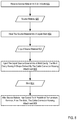
- FIG. 8 sets forth a flow chart illustrating an exemplary method for manufacturing a cable connector housing attachment for protecting and directing a cable according to embodiments of the present invention.
- the example method of FIG. 8 includes receiving ( 802 ) source material ( 820 ) in a solid state.
- source material may include metal, glass, elastomers, thermoplastic and thermosetting polymers, among others.
- Receiving ( 802 ) such source material may be carried out in various ways including, for example, by receiving plastic granules in a hopper.
- the method of FIG. 8 also includes heating ( 804 ) the source material ( 820 ) into a liquid state to obtain liquid source material ( 822 ).
- Heating ( 804 ) the source material into a liquid state may be carried out in a variety of ways including, for example, by forcing the granules through a barrel by a reciprocating screw, where a heater increases the temperature of the source material while the source material travels down the barrel.
- the method of FIG. 8 also includes injecting ( 806 ) the liquid source material ( 822 ) into a mold ( 824 ) cavity.
- Injecting ( 806 ) the liquid material into a mold cavity may be carried out in various ways including, for example, by forcing the heated, liquid material through a nozzle at the end of the barrel by the reciprocating screw.
- the mold ( 824 ) cavity has a shape defined by a cable connector housing attachment for protecting and directing a cable similar to those described above.
- the mold is configured with a cavity that forms the dimension of a cable connector housing attachment for protecting and directing a cable that includes: an anchor portion configured for attachment to a cable connector housing; and a cable guide portion comprising a base wall, a first side wall, and a second side wall each extending from the anchor portion in the direction of the cable from the cable connector housing, where the first side wall comprises a guiding edge opposite the anchor portion, where the guiding edge creates a non-parallel and non-perpendicular angle relative to the direction of the cable from the cable connector housing, and where the guiding edge directs a bend of the cable in a direction offset from the direction of the cable from the cable connector housing.
- the method of FIG. 8 also includes removing ( 808 ), from the mold after the liquid source material ( 822 ) is cooled to a predefined temperature, the cable connector housing attachment. Removing the cable connector housing attachment from the mold may be carried out by removing a top portion of the mold from a bottom portion. Further, once removed, the cable connector housing attachment may be clamped in a position to ensure that during future cooling to a second predefined temperature (room temperature in some embodiments) the deformation of the cable connector housing attachment is reduced.
- a second predefined temperature room temperature in some embodiments
Landscapes
- Engineering & Computer Science (AREA)
- Manufacturing & Machinery (AREA)
- Mechanical Engineering (AREA)
- Details Of Connecting Devices For Male And Female Coupling (AREA)
Abstract
A cable connector housing attachment for protecting and directing a cable including an anchor portion configured for attachment to a cable connector housing; and a cable guide portion comprising a base wall, a first side wall, and a second side wall each extending from the anchor portion in the direction of the cable from the cable connector housing, wherein the first side wall comprises a guiding edge opposite the anchor portion, wherein the guiding edge creates a non-parallel and non-perpendicular angle relative to the direction of the cable from the cable connector housing, and wherein the guiding edge directs a bend of the cable in a direction offset from the direction of the cable from the cable connector housing.
Description
The field of the invention is cable connector housing attachments, or, more specifically, products and methods of manufacture for a cable connector housing attachment for protecting and directing a cable.
The development of the EDVAC computer system of 1948 is often cited as the beginning of the computer era. Since that time, computer systems have evolved into extremely complicated devices. Today's computers are much more sophisticated than early systems such as the EDVAC. Computer systems typically include a combination of hardware and software components, application programs, operating systems, processors, buses, memory, input/output devices, and so on. As advances in semiconductor processing and computer architecture push the performance of the computer higher and higher, more sophisticated computer software has evolved to take advantage of the higher performance of the hardware, resulting in computer systems today that are much more powerful than just a few years ago. These advances in computer systems has led to ever more complicated cabling schemes between components within the computer system. Cables for frequently moved or replaced components may become damaged over time due to stress.
Products and methods of manufacture for a cable connector housing attachment for protecting and directing a cable. The cable connector housing attachment for protecting and directing a cable includes an anchor portion configured for attachment to a cable connector housing; and a cable guide portion comprising a base wall, a first side wall, and a second side wall each extending from the anchor portion in the direction of the cable from the cable connector housing, wherein the first side wall comprises a guiding edge opposite the anchor portion, wherein the guiding edge creates a non-parallel and non-perpendicular angle relative to the direction of the cable from the cable connector housing, and wherein the guiding edge directs a bend of the cable in a direction offset from the direction of the cable from the cable connector housing.
The foregoing and other objects, features and advantages of the invention will be apparent from the following more particular descriptions of exemplary embodiments of the invention as illustrated in the accompanying drawings wherein like reference numbers generally represent like parts of exemplary embodiments of the invention.
Computer cables, particularly cables within computer housing, often need to be guided along convoluted paths between components. These paths may cause the cable to collide or otherwise interface with components within the system, which creates a number of problems, including bending a cable at a bend radius that is less than the minimum specified, applying a force that creates torsion at the interface between cable and cable connector housing, and applying a force that causes stress along the cable itself. Further, relatively stiff cables may require a sturdy implement to generate enough force to flex the cable as desired. Finally, some computer housing setups may require a tight but controlled cable bend but lack available mount points within the housing structure.
Exemplary products and methods of manufacture for a cable connector housing attachment for protecting and directing a cable in accordance with the present invention are described with reference to the accompanying drawings, beginning with FIG. 1 and FIG. 2 . FIG. 1 sets forth a perspective view of an example cable connector housing attachment for protecting and directing a cable according to embodiments of the present invention. FIG. 2 shows the cable connector housing attachment (100) attached to a cable connector housing (202) and a cable (200) extending from the cable connector housing (202). The cable connector housing attachment (100) includes an anchor portion (112) and a cable guide portion (102). The cable guide portion (102) includes a base wall (104), a side wall (110), and a guiding wall (106). The guiding wall (106) includes a guiding edge (108) on the edge opposite the anchor portion (100). The cable connector housing attachment (100) may be a single piece or include multiple pieces. Further, the cable connector housing attachment (100) may comprise one or more materials, such as plastic or metal.
The anchor portion (112) attaches to the cable connector housing to minimize movement of the cable connector housing attachment (100) relative to the cable connector housing (202). The inner side of one or more walls of the anchor portion (112) may rest flush or nearly flush against at least one side of the cable connector housing (202). The cable connector housing attachment (100) may attach to the cable connector housing (200) and/or the cable (102) at one or more points to control the direction at which the cable twists, turns, or bends. The cable connector housing attachment (100) may attach to the cable connector housing (202) in a variety of ways, including only friction, with the aid of an anchor base extension (as shown in FIG. 4 ), or with the aid of an attachment mechanism, such as a hook or clip (as shown in FIGS. 3, 4, 6 , and 7).
The anchor portion (112) and the cable guide portion (102) may be different sizes (as shown in FIGS. 1-6 ) or the same or similar sizes (as shown in FIG. 7 ). In the example shown in FIG. 1 and FIG. 2 , the walls of the anchor portion (112) along the axis perpendicular to the direction of the cable (200) from the cable connector housing (202) are larger in dimension than the adjacent walls of the cable guide portion (102). In other words, the dimension of each wall of the anchor portion (112) along and adjacent to the cable guide portion (102) is greater than the dimension of each wall of the cable guide portion (102) along and adjacent to the anchor portion (112).
The cable guide portion (102) houses the cable (200) near the point at which the cable (200) attaches to the cable connector housing (202). The cable (200) may be a ribbon cable as shown in FIGS. 2-6 , or another type of cable as shown in FIG. 7 . The cable guide portion (102) guides or bends the cable (200) in a direction dictated by the angle of the guiding edge (108).
The base wall (104) extends from the anchor portion (112) to create a stable channel between the side wall (110) and the guiding wall (106). The base wall (104) also prevents the cable from bending directly at the cable connector housing. The side wall (110) extends from the anchor portion (112) and also prevents the cable from bending directly at the cable connector housing.
The guiding wall (106) is a side wall that includes the guiding edge (108). The guiding wall (106) extends from the anchor portion (112) to the guiding edge (108). The guiding edge (108) is the edge opposite the anchor portion (112) over which the cable (200) guided or bent. The guiding edge (108) creates a non-parallel and non-perpendicular angle relative to the direction of the cable (200) from the cable connector housing (202). In other words, the guiding edge (108) is not parallel to the direction of the cable (200) from the cable connector housing (202) and is also not perpendicular to the direction of the cable (200) from the cable connector housing (202). The angle of the guiding edge (108) may be less than 90 degrees offset from the angle of the direction of the cable (200) from the cable connector housing (202).
The guiding edge (108) may also provide a sturdy pivot location over which a stiffer cable (200) may be bent. Specifically, the guiding edge (108) may provide a counter force to the force necessary to flex a stiffer cable (200) at a particular angle, preventing the cable (200) from bending at the cable connector housing (202).
The cable connector housing attachment (100) of FIG. 7 also includes a guiding edge (108) with a curved lip. The curved lip may increase the size of a bend radius for the cable (200) along the guiding edge (108). The curved lip may be of a size that prevents the cable (200) from bending at a radius less than the specification for the cable (200). The thickness of the guiding wall (106) may be used in a similar manner as a curved lip. Specifically, the guiding wall (106) may be of a thickness that prevents the cable (200) from bending at a radius less than the specification for the cable (200).
For further explanation, FIG. 8 sets forth a flow chart illustrating an exemplary method for manufacturing a cable connector housing attachment for protecting and directing a cable according to embodiments of the present invention. The example method of FIG. 8 includes receiving (802) source material (820) in a solid state. Such source material may include metal, glass, elastomers, thermoplastic and thermosetting polymers, among others. Receiving (802) such source material may be carried out in various ways including, for example, by receiving plastic granules in a hopper.
The method of FIG. 8 also includes heating (804) the source material (820) into a liquid state to obtain liquid source material (822). Heating (804) the source material into a liquid state may be carried out in a variety of ways including, for example, by forcing the granules through a barrel by a reciprocating screw, where a heater increases the temperature of the source material while the source material travels down the barrel.
The method of FIG. 8 also includes injecting (806) the liquid source material (822) into a mold (824) cavity. Injecting (806) the liquid material into a mold cavity may be carried out in various ways including, for example, by forcing the heated, liquid material through a nozzle at the end of the barrel by the reciprocating screw. In the example of FIG. 8 , the mold (824) cavity has a shape defined by a cable connector housing attachment for protecting and directing a cable similar to those described above. That is, the mold is configured with a cavity that forms the dimension of a cable connector housing attachment for protecting and directing a cable that includes: an anchor portion configured for attachment to a cable connector housing; and a cable guide portion comprising a base wall, a first side wall, and a second side wall each extending from the anchor portion in the direction of the cable from the cable connector housing, where the first side wall comprises a guiding edge opposite the anchor portion, where the guiding edge creates a non-parallel and non-perpendicular angle relative to the direction of the cable from the cable connector housing, and where the guiding edge directs a bend of the cable in a direction offset from the direction of the cable from the cable connector housing.
The method of FIG. 8 also includes removing (808), from the mold after the liquid source material (822) is cooled to a predefined temperature, the cable connector housing attachment. Removing the cable connector housing attachment from the mold may be carried out by removing a top portion of the mold from a bottom portion. Further, once removed, the cable connector housing attachment may be clamped in a position to ensure that during future cooling to a second predefined temperature (room temperature in some embodiments) the deformation of the cable connector housing attachment is reduced.
In view of the explanations set forth above, readers will recognize that the benefits of a cable connector housing attachment for protecting and directing a cable according to embodiments of the present invention include:
-
- ensuring the bend radius of a cable is equal to or greater than the minimum specified;
- ensuring the cable path does not have significant bending or torsion near the cable connector housing;
- absorbing forces exerted along the axis of the cable, preventing strain.
It will be understood from the foregoing description that modifications and changes may be made in various embodiments of the present invention without departing from its true spirit. The descriptions in this specification are for purposes of illustration only and are not to be construed in a limiting sense. The scope of the present invention is limited only by the language of the following claims.
Claims (17)
1. An electrical cable connector housing attachment for protecting and directing a cable comprising:
an anchor portion configured for attachment to a cable connector housing; and
a cable guide portion comprising a base wall, a first side wall, and a second side wall each extending from the anchor portion in the direction of the cable from the cable connector housing,
wherein the first side wall comprises an angle guiding edge opposite the anchor portion, wherein the angle guiding edge creates a non-parallel and non-perpendicular angle relative to the direction of the cable from the electrical cable connector housing,
wherein the angle guiding edge directs a bend of the cable in a direction offset from the direction of the cable from the electrical cable connector housing; and
wherein the angle guiding edge comprises a curved lip along the angle guiding edge.
2. The cable connector housing attachment of claim 1 , wherein the anchor portion comprises a cavity configured to receive an attachment mechanism of the cable connector housing.
3. The cable connector housing attachment of claim 1 , wherein the anchor portion comprises an anchor base extension that partially extends over one side of the anchor portion.
4. The cable connector housing attachment of claim 1 , wherein the anchor portion comprises a hook that attaches the anchor portion to the cable connector housing.
5. The cable connector housing attachment of claim 1 , wherein the anchor portion comprises a clip that attaches the anchor portion to the cable connector housing.
6. The cable connector housing attachment of claim 1 , wherein a dimension of a wall of the anchor portion adjacent to the cable guide portion is greater than a dimension of a wall of the cable guide portion adjacent to the anchor portion.
7. An injection mold comprising:
a cavity configured to receive liquid, injected material, the cavity having a shape defined by an electrical cable connector housing attachment for protecting and directing a cable, the electrical cable connector housing attachment comprising:
an anchor portion configured for attachment to the electrical cable connector housing; and a cable guide portion comprising a base wall, a first side wall, and a second side wall each extending from the anchor portion in the direction of the cable from the electrical cable connector housing,
wherein the first side wall comprises an angle guiding edge opposite the anchor portion,
wherein the angle guiding edge creates a non-parallel and non-perpendicular angle relative to the direction of the cable from the electrical cable connector housing,
wherein the angle guiding edge directs a bend of the cable in a direction offset from the direction of the cable from the electrical cable connector housing; and
wherein the angle guiding edge comprises a curved lip along the angle guiding edge.
8. The injection mold of claim 7 , wherein the anchor portion comprises a cavity configured to receive an attachment mechanism of the cable connector housing.
9. The injection mold of claim 7 , wherein the anchor portion comprises an anchor base extension that partially extends over one side of the anchor portion.
10. The injection mold of claim 7 , wherein the anchor portion comprises a hook that attaches the anchor portion to the cable connector housing.
11. The injection mold of claim 7 , wherein the anchor portion comprises a clip that attaches the anchor portion to the cable connector housing.
12. The injection mold of claim 7 , wherein a dimension of a wall of the anchor portion adjacent to the cable guide portion is greater than a dimension of a wall of the cable guide portion adjacent to the anchor portion.
13. A method of manufacturing an electrical cable connector housing attachment for protecting and directing a cable, the method comprising:
receiving source material in a solid state;
heating the source material into a liquid state; and
injecting the liquid source material into a mold cavity, the mold cavity having a shape defined by the electrical cable connector housing attachment, the electrical cable connector housing attachment comprising:
an anchor portion configured for attachment to an electrical cable connector housing; and
a cable guide portion comprising a base wall, a first side wall, and a second side wall each extending from the anchor portion in the direction of the cable from the electrical cable connector housing,
wherein the first side wall comprises an angle guiding edge opposite the anchor portion, wherein the angle guiding edge creates a non-parallel and non-perpendicular angle relative to the direction of the cable from the electrical cable connector housing, and
wherein the angle guiding edge directs a bend of the cable in a direction offset from the direction of the cable from the electrical cable connector housing; and
wherein the angle guiding edge comprises a curved lip along the angle guiding edge.
14. The method of claim 13 , wherein the anchor portion comprises a cavity configured to receive an attachment mechanism of the cable connector housing.
15. The method of claim 13 , wherein the anchor portion comprises an anchor base extension that partially extends over one side of the anchor portion.
16. The method of claim 13 , wherein the anchor portion comprises a hook that attaches the anchor portion to the cable connector housing.
17. The method of claim 13 , wherein the anchor portion comprises a clip that attaches the anchor portion to the cable connector housing.
Priority Applications (1)
| Application Number | Priority Date | Filing Date | Title |
|---|---|---|---|
| US16/540,754 US10833445B1 (en) | 2019-08-14 | 2019-08-14 | Cable connector housing attachment for protecting and directing a cable |
Applications Claiming Priority (1)
| Application Number | Priority Date | Filing Date | Title |
|---|---|---|---|
| US16/540,754 US10833445B1 (en) | 2019-08-14 | 2019-08-14 | Cable connector housing attachment for protecting and directing a cable |
Publications (1)
| Publication Number | Publication Date |
|---|---|
| US10833445B1 true US10833445B1 (en) | 2020-11-10 |
Family
ID=73052179
Family Applications (1)
| Application Number | Title | Priority Date | Filing Date |
|---|---|---|---|
| US16/540,754 Expired - Fee Related US10833445B1 (en) | 2019-08-14 | 2019-08-14 | Cable connector housing attachment for protecting and directing a cable |
Country Status (1)
| Country | Link |
|---|---|
| US (1) | US10833445B1 (en) |
Citations (10)
| Publication number | Priority date | Publication date | Assignee | Title |
|---|---|---|---|---|
| US3333667A (en) | 1965-12-09 | 1967-08-01 | Teletype Corp | Flexible wire guide cable |
| US4840023A (en) | 1986-09-15 | 1989-06-20 | Tecno S.P.A. Mobili E Forniture Per Arredamento | Flexible cable guide with two-directional joints |
| US5394297A (en) | 1992-09-18 | 1995-02-28 | Ast Research, Inc. | Apparatus and method for reducing bending stress on an electrical cable using a freely rotatable bushing |
| CN1220016A (en) | 1996-06-10 | 1999-06-16 | 明尼苏达矿业和制造公司 | Bending Radius Control Sheath with Matrix of Engaged Parts |
| US6193544B1 (en) * | 1999-11-04 | 2001-02-27 | Jae Electronics, Inc. | Flexible circuit service connector |
| US6305970B1 (en) * | 1999-11-29 | 2001-10-23 | Yazaki Corporation | Terminal end structure of flat circuitry and branch connection structure constituted by the same |
| US6464534B1 (en) * | 2000-10-04 | 2002-10-15 | Fci Usa, Inc. | Flexible circuit assembly having a flexible circuit support connected to a flexible circuit |
| US20040186350A1 (en) | 2003-01-13 | 2004-09-23 | Usgi Medical Corp. | Apparatus and methods for guiding an endoscope via a rigidizable wire guide |
| US7241165B2 (en) * | 2005-10-28 | 2007-07-10 | Weidmüller Interface GmbH & Co. KG | Electrical connector for flat cables and contact element therefor |
| US7551748B2 (en) | 2004-03-26 | 2009-06-23 | Star Micronics Co., Ltd. | Earphone |
-
2019
- 2019-08-14 US US16/540,754 patent/US10833445B1/en not_active Expired - Fee Related
Patent Citations (10)
| Publication number | Priority date | Publication date | Assignee | Title |
|---|---|---|---|---|
| US3333667A (en) | 1965-12-09 | 1967-08-01 | Teletype Corp | Flexible wire guide cable |
| US4840023A (en) | 1986-09-15 | 1989-06-20 | Tecno S.P.A. Mobili E Forniture Per Arredamento | Flexible cable guide with two-directional joints |
| US5394297A (en) | 1992-09-18 | 1995-02-28 | Ast Research, Inc. | Apparatus and method for reducing bending stress on an electrical cable using a freely rotatable bushing |
| CN1220016A (en) | 1996-06-10 | 1999-06-16 | 明尼苏达矿业和制造公司 | Bending Radius Control Sheath with Matrix of Engaged Parts |
| US6193544B1 (en) * | 1999-11-04 | 2001-02-27 | Jae Electronics, Inc. | Flexible circuit service connector |
| US6305970B1 (en) * | 1999-11-29 | 2001-10-23 | Yazaki Corporation | Terminal end structure of flat circuitry and branch connection structure constituted by the same |
| US6464534B1 (en) * | 2000-10-04 | 2002-10-15 | Fci Usa, Inc. | Flexible circuit assembly having a flexible circuit support connected to a flexible circuit |
| US20040186350A1 (en) | 2003-01-13 | 2004-09-23 | Usgi Medical Corp. | Apparatus and methods for guiding an endoscope via a rigidizable wire guide |
| US7551748B2 (en) | 2004-03-26 | 2009-06-23 | Star Micronics Co., Ltd. | Earphone |
| US7241165B2 (en) * | 2005-10-28 | 2007-07-10 | Weidmüller Interface GmbH & Co. KG | Electrical connector for flat cables and contact element therefor |
Similar Documents
| Publication | Publication Date | Title |
|---|---|---|
| US4566660A (en) | Cradle clip | |
| CN106104337B (en) | Optical Connector | |
| CN109672127B (en) | grommet | |
| KR101455712B1 (en) | Protective guide for cables and bracket used for the protective guide | |
| US10833445B1 (en) | Cable connector housing attachment for protecting and directing a cable | |
| US20120255153A1 (en) | Tool-less backplane retention for computer hardware | |
| US9896042B2 (en) | Grommet and wire harness | |
| CN101426700A (en) | Clamping device | |
| CN113357489B (en) | Mounting bracket | |
| US11877515B2 (en) | Actuator and tactile sensation providing apparatus | |
| WO2009009051A1 (en) | Cable guide | |
| US10775842B1 (en) | Portable electronic device | |
| US10653040B1 (en) | Apparatus for changing airflow in a server | |
| CN108063421A (en) | Bending restricts component, the protection tube assembly of component is restricted with the bending and supplies electric installation with the protection tube assembly | |
| WO1982002239A1 (en) | Plastics clips | |
| JP6236581B1 (en) | Wind nail corrector | |
| US10971874B2 (en) | Lock mechanism and bus bar module | |
| CN105579878A (en) | Optical fiber cable management apparatuses with storage hub components | |
| US12612996B2 (en) | Wall mount assembly and wall mount bracket | |
| CN208123208U (en) | Tommyhead bolt | |
| US20080041608A1 (en) | Cable Duct | |
| KR102325582B1 (en) | fiber Ribbonizing applicator | |
| CN218598534U (en) | Fixing structure and fixing device of video line connector | |
| CN205846613U (en) | Clamp device for fixed cable | |
| US11769978B2 (en) | Assembly system |
Legal Events
| Date | Code | Title | Description |
|---|---|---|---|
| FEPP | Fee payment procedure |
Free format text: ENTITY STATUS SET TO UNDISCOUNTED (ORIGINAL EVENT CODE: BIG.); ENTITY STATUS OF PATENT OWNER: LARGE ENTITY |
|
| STCF | Information on status: patent grant |
Free format text: PATENTED CASE |
|
| LAPS | Lapse for failure to pay maintenance fees |
Free format text: PATENT EXPIRED FOR FAILURE TO PAY MAINTENANCE FEES (ORIGINAL EVENT CODE: EXP.); ENTITY STATUS OF PATENT OWNER: LARGE ENTITY |
|
| STCH | Information on status: patent discontinuation |
Free format text: PATENT EXPIRED DUE TO NONPAYMENT OF MAINTENANCE FEES UNDER 37 CFR 1.362 |
|
| FP | Lapsed due to failure to pay maintenance fee |
Effective date: 20241110 |