FIELD OF THE INVENTION
This disclosure relates generally to the mounting and positioning of optical components, and in particular to mounting and positioning of a mirror or other optical component requiring tip-tilt or piston-tip-tilt adjustments.
BACKGROUND
Optical systems require accuracy and stability in positioning of optical components and in many cases said components must have adjustment capabilities to achieve system performance. In particular, system alignment is often achieved via “pointing adjustment” of reflective components such as mirrors, using mounts with two rotational degrees of freedom around axes perpendicular to reflective surface normal, often termed “tip-tilt”.
Conventional approaches for mirror mounting and adjustment include kinematic mounts, flexure mounts, and gimbal mounts. These mounts are often complex and require precision machining. The optical element is usually mounted in a flame putting metal surfaces in close proximity to the retained optic, which can be undesirable in high power laser applications. The additional weight of an optical element retainer makes conventional mounts ill-suited for applications requiring rapid adjustments, such as fast steering mirrors.
Therefore, a need exists for a novel approach to adjustable mirror mount that would address the drawbacks of conventional approaches. Furthermore, a simpler, more compact design and lower cost are the attributes which are always in demand.
BRIEF SUMMARY OF THE INVENTION
This invention comprises a novel method and apparatus for implementing a flexible magnetic joint and application of said flexible magnetic joint in tip-tilt and piston-tip-tilt optical mounts. The invention employs a magnetic joint which, in its basic embodiment, consists of two interfacing parts: one having a flat surface interfacing a convex surface of the other. One or both parts of the magnetic joint are made from permanent magnets which are magnetized along the axis of the joint, or one of the parts is made from a ferromagnetic material thus creating magnetic force attraction between the two parts.
Unlike conventional magnetic joints which utilize matching spherical surfaces and only allowing three rotational degrees of freedom, the magnetic joint of this invention does not mechanically constrain the translational degrees of freedom perpendicular to the joint axis. This feature of the magnetic joint of this invention is critical to its application to tip-tilt mounts. When travel of actuators in a tip-tilt mount is constrained to parallel axes, the distance between points defining the plane of an optical element or its holder is not constant. The magnetic joint of this invention allows for simple, uniform design where the optical element or its mount are decoupled from actuators through the lack of lateral mechanical constraint between the two joint components, while magnetic force provides retention sufficient for wide variety of applications.
BRIEF DESCRIPTION OF THE DRAWINGS
Embodiments of the present invention are illustrated as examples and are not limited by the figures of the accompanied drawings, in which like reference may indicate similar elements and in which:
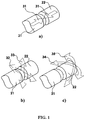
FIG. 1 depicts a perspective view of the basic embodiment of the laterally unconstrained magnetic joint and its degrees of freedom.
FIG. 2 shows perspective views with quarter sections of possible embodiments of the laterally unconstrained magnetic joint.
FIG. 3 shows a perspective view of an example of a mirror mount embodiment with side section views of the possible laterally unconstrained magnetic joint embodiments.
FIG. 4 shows perspective views of possible laterally unconstrained magnetic joint arrangements when used in mirror mount embodiments
DETAILED DESCRIPTION OF THE INVENTION
The terminology used herein is for the purpose of describing particular embodiments only and is not intended to limit the invention. The term “and/or” includes any and all combinations of one or more of the associated listed items. The singular forms “a”, “an”, and “the” are intended to include the plural forms as well as singular forms, unless the context clearly indicates otherwise. It will be further understood that the terms “comprises” and/or “comprising”, when used in this specification, indicate the presence of stated features, elements, and/or components, but do not preclude the presence or addition of one or more other features, elements, components, and/or groups thereof.
The present disclosure is to be considered as an exemplification of the invention, and is not intended to limit the invention to the specific embodiments illustrated by figures or description below.
The present invention will now be described by referencing the appended figures representing preferred embodiments. FIG. 1 depicts a perspective view of the basic embodiment of the laterally unconstrained magnetic joint (the “joint”). The joint consists of two components 21 and 22 interfacing each other: one component 22 having a flat interface surface, and the other component 21 having a convex interface surface.
One embodiment of the joint comprises both components 21 and 22 made from a permanent magnet material magnetized in the same direction along the joint axis 31. Another embodiment of the joint comprises one component made from a permanent magnet material and another from a ferromagnetic material. In both cases there is a magnetic force attracting the two components of the joint together along the joint axis 31 as shown in FIG. 1.a).
By the nature of the interface between the flat and the convex surface the two components 21 and 22 of the joint are free to move laterally as shown in FIG. 1.b). While in most embodiments, the convex surface is expected to be spherical, any other continuous convex surface which allows desired range of tip-tilt motion is within the scope and spirit of this invention. For all possible geometries of the two joint components 21 and 22, there will be a position of one relative to another when the lateral magnetic forces are at equilibrium. For rotationally symmetric embodiments, this condition is satisfied, gravity and other forces not considered, when the symmetry axes of each component are collinear. Lateral displacement 32, 33 of the two components 21 and 22 relative to each other results in magnetic force towards the said equilibrium condition thus providing retention within the joint.
The joint is free to articulate within all three rotational degrees of freedom, the two of which 34 and 35 are around the axes perpendicular to the joint axis 31. The articulation 34 and 35 as shown in FIG. 1.c) is limited by the extent of the convex surface of the joint component 21.
Examples of the joint embodiments are depicted in FIG. 2. The basic joint embodiment as described in previous paragraphs is shown in FIG. 2.a). FIG. 2.b) depicts an example of embodiment where the joint interface surfaces are concave and convex with convex having a greater curvature so that lateral motion of the joint is permitted. In general, this invention covers embodiments of any surface pair configuration that permits lateral motion between the two joint components 21 and 22.
In another embodiment the joint may have a component 23 as shown in FIG. 2.c) that improves bearing properties of the joint. Such component 23 may float between the two joint components 21 and 22, be attached to one of the joint components, or be a surface coating of either or both joint components 21 and 22.
In another embodiment the joint may include ferromagnetic fluid (“ferrofluid”) 24 as shown in FIG. 2.d), which can be used to increase the magnetic force attracting the two joint components together, and/or improve the bearing properties by lubricating the interfacing surfaces of the joint.
An example of a mirror mount embodiment utilizing the laterally unconstrained magnetic joint (“mount”) is depicted in FIG. 3. The mount would utilize three joints 11 arranged in any configuration other than a line, thus defining a plane with three points in space. On one side, all three joints 11 would interface a mirror, mirror mount, or any other type of payload 12. This interface can have numerous embodiments, which are outside of the scope of this invention. On the other side of the joint, an embodiment of an optical mount providing piston-tip-tilt functionality would have all three joints 11 interfacing an adjustor or linear actuator 13; and an embodiment of an optical mount providing tip-tilt functionality would have two joints 11 interfacing an adjustor or linear actuator 13, while the third joint 11 will be statically attached to a reference point.
Embodiment of adjustors and linear actuators 13 is outside of the scope of this invention and can be any combination of manual or motorized types including but not limited to: screws, fine-pitch screws, micrometers, differential screws, piezo actuators, leadscrews, ball-screws, roller screws, rack and pinions, chain drives, belt drives, hydraulic, pneumatic, voice-coils, linear drives, etc.
While most embodiments are expected to have the adjustors and linear actuators 13 act along parallel axes, other embodiments may have different configurations. As long as such embodiments utilize the laterally unconstrained magnetic joint as described by this invention to decouple the adjustment and/or actuation mechanism from the mirror, mirror mount, or any other type of payload, they are within the scope and spirit of this invention
Examples of embodiments of an actuator 13—joint 11 arrangements within a mount are shown in FIG. 4. Equilateral triangle arrangement shown in FIG. 4.a) provides symmetrical mounting of the payload, equalizing the forces seen by joints 11 under uniform operating conditions. The drawback of equilateral arrangement is non-orthogonal actuation during adjustment. Orthogonal arrangement depicted in FIG. 4.b) is functionally equivalent to conventional tip-tilt mounts which utilize cone, groove, and flat constraint systems. Another embodiment shown in FIG. 4.c) is close functional equivalent of gimbal mounts, which minimize path length variation during adjustment.
Although this invention has been illustrated and described herein with reference to preferred embodiments and specific examples thereof, it will be readily apparent to those of ordinary skill in the art that other embodiments and examples may perform similar functions and/or achieve like results. All such equivalent embodiments and examples are within the spirit and scope of this invention, are contemplated thereby, and are intended to be covered by the following claims.