US10830988B2 - Laterally unconstrained magnetic joint for tip tilt and piston-tip-tilt mounts - Google Patents
Laterally unconstrained magnetic joint for tip tilt and piston-tip-tilt mounts Download PDFInfo
- Publication number
- US10830988B2 US10830988B2 US16/125,758 US201816125758A US10830988B2 US 10830988 B2 US10830988 B2 US 10830988B2 US 201816125758 A US201816125758 A US 201816125758A US 10830988 B2 US10830988 B2 US 10830988B2
- Authority
- US
- United States
- Prior art keywords
- joint
- interface
- axis
- magnetic
- magnetic joint
- Prior art date
- Legal status (The legal status is an assumption and is not a legal conclusion. Google has not performed a legal analysis and makes no representation as to the accuracy of the status listed.)
- Active, expires
Links
- 230000005291 magnetic effect Effects 0.000 title claims abstract description 55
- 239000003302 ferromagnetic material Substances 0.000 claims abstract description 5
- 239000011248 coating agent Substances 0.000 claims description 6
- 238000000576 coating method Methods 0.000 claims description 6
- 239000012530 fluid Substances 0.000 claims description 4
- 230000005294 ferromagnetic effect Effects 0.000 claims description 3
- 239000000463 material Substances 0.000 claims description 3
- 239000011554 ferrofluid Substances 0.000 claims description 2
- 230000003287 optical effect Effects 0.000 abstract description 12
- 230000014759 maintenance of location Effects 0.000 abstract description 3
- 238000013459 approach Methods 0.000 description 3
- 238000006073 displacement reaction Methods 0.000 description 1
- 230000005484 gravity Effects 0.000 description 1
- 230000001050 lubricating effect Effects 0.000 description 1
- 238000003754 machining Methods 0.000 description 1
- 239000002184 metal Substances 0.000 description 1
- 238000000034 method Methods 0.000 description 1
- 230000000717 retained effect Effects 0.000 description 1
Images


Classifications
-
- G—PHYSICS
- G02—OPTICS
- G02B—OPTICAL ELEMENTS, SYSTEMS OR APPARATUS
- G02B7/00—Mountings, adjusting means, or light-tight connections, for optical elements
- G02B7/18—Mountings, adjusting means, or light-tight connections, for optical elements for prisms; for mirrors
- G02B7/182—Mountings, adjusting means, or light-tight connections, for optical elements for prisms; for mirrors for mirrors
- G02B7/1822—Mountings, adjusting means, or light-tight connections, for optical elements for prisms; for mirrors for mirrors comprising means for aligning the optical axis
- G02B7/1827—Motorised alignment
- G02B7/1828—Motorised alignment using magnetic means
-
- F—MECHANICAL ENGINEERING; LIGHTING; HEATING; WEAPONS; BLASTING
- F16—ENGINEERING ELEMENTS AND UNITS; GENERAL MEASURES FOR PRODUCING AND MAINTAINING EFFECTIVE FUNCTIONING OF MACHINES OR INSTALLATIONS; THERMAL INSULATION IN GENERAL
- F16C—SHAFTS; FLEXIBLE SHAFTS; ELEMENTS OR CRANKSHAFT MECHANISMS; ROTARY BODIES OTHER THAN GEARING ELEMENTS; BEARINGS
- F16C11/00—Pivots; Pivotal connections
- F16C11/04—Pivotal connections
-
- G—PHYSICS
- G02—OPTICS
- G02B—OPTICAL ELEMENTS, SYSTEMS OR APPARATUS
- G02B7/00—Mountings, adjusting means, or light-tight connections, for optical elements
- G02B7/003—Alignment of optical elements
-
- G—PHYSICS
- G02—OPTICS
- G02B—OPTICAL ELEMENTS, SYSTEMS OR APPARATUS
- G02B7/00—Mountings, adjusting means, or light-tight connections, for optical elements
- G02B7/18—Mountings, adjusting means, or light-tight connections, for optical elements for prisms; for mirrors
- G02B7/182—Mountings, adjusting means, or light-tight connections, for optical elements for prisms; for mirrors for mirrors
- G02B7/198—Mountings, adjusting means, or light-tight connections, for optical elements for prisms; for mirrors for mirrors with means for adjusting the mirror relative to its support
-
- G—PHYSICS
- G03—PHOTOGRAPHY; CINEMATOGRAPHY; ANALOGOUS TECHNIQUES USING WAVES OTHER THAN OPTICAL WAVES; ELECTROGRAPHY; HOLOGRAPHY
- G03F—PHOTOMECHANICAL PRODUCTION OF TEXTURED OR PATTERNED SURFACES, e.g. FOR PRINTING, FOR PROCESSING OF SEMICONDUCTOR DEVICES; MATERIALS THEREFOR; ORIGINALS THEREFOR; APPARATUS SPECIALLY ADAPTED THEREFOR
- G03F7/00—Photomechanical, e.g. photolithographic, production of textured or patterned surfaces, e.g. printing surfaces; Materials therefor, e.g. comprising photoresists; Apparatus specially adapted therefor
- G03F7/70—Microphotolithographic exposure; Apparatus therefor
- G03F7/708—Construction of apparatus, e.g. environment aspects, hygiene aspects or materials
- G03F7/70808—Construction details, e.g. housing, load-lock, seals or windows for passing light in or out of apparatus
- G03F7/70825—Mounting of individual elements, e.g. mounts, holders or supports
-
- F—MECHANICAL ENGINEERING; LIGHTING; HEATING; WEAPONS; BLASTING
- F16—ENGINEERING ELEMENTS AND UNITS; GENERAL MEASURES FOR PRODUCING AND MAINTAINING EFFECTIVE FUNCTIONING OF MACHINES OR INSTALLATIONS; THERMAL INSULATION IN GENERAL
- F16C—SHAFTS; FLEXIBLE SHAFTS; ELEMENTS OR CRANKSHAFT MECHANISMS; ROTARY BODIES OTHER THAN GEARING ELEMENTS; BEARINGS
- F16C2226/00—Joining parts; Fastening; Assembling or mounting parts
- F16C2226/10—Force connections, e.g. clamping
- F16C2226/18—Force connections, e.g. clamping by magnets, i.e. magnetic attraction to hold parts together
-
- F—MECHANICAL ENGINEERING; LIGHTING; HEATING; WEAPONS; BLASTING
- F16—ENGINEERING ELEMENTS AND UNITS; GENERAL MEASURES FOR PRODUCING AND MAINTAINING EFFECTIVE FUNCTIONING OF MACHINES OR INSTALLATIONS; THERMAL INSULATION IN GENERAL
- F16C—SHAFTS; FLEXIBLE SHAFTS; ELEMENTS OR CRANKSHAFT MECHANISMS; ROTARY BODIES OTHER THAN GEARING ELEMENTS; BEARINGS
- F16C2370/00—Apparatus relating to physics, e.g. instruments
- F16C2370/20—Optical, e.g. movable lenses or mirrors; Spectacles
Definitions
- This disclosure relates generally to the mounting and positioning of optical components, and in particular to mounting and positioning of a mirror or other optical component requiring tip-tilt or piston-tip-tilt adjustments.
- Optical systems require accuracy and stability in positioning of optical components and in many cases said components must have adjustment capabilities to achieve system performance.
- system alignment is often achieved via “pointing adjustment” of reflective components such as mirrors, using mounts with two rotational degrees of freedom around axes perpendicular to reflective surface normal, often termed “tip-tilt”.
- This invention comprises a novel method and apparatus for implementing a flexible magnetic joint and application of said flexible magnetic joint in tip-tilt and piston-tip-tilt optical mounts.
- the invention employs a magnetic joint which, in its basic embodiment, consists of two interfacing parts: one having a flat surface interfacing a convex surface of the other.
- One or both parts of the magnetic joint are made from permanent magnets which are magnetized along the axis of the joint, or one of the parts is made from a ferromagnetic material thus creating magnetic force attraction between the two parts.
- the magnetic joint of this invention does not mechanically constrain the translational degrees of freedom perpendicular to the joint axis.
- This feature of the magnetic joint of this invention is critical to its application to tip-tilt mounts. When travel of actuators in a tip-tilt mount is constrained to parallel axes, the distance between points defining the plane of an optical element or its holder is not constant.
- the magnetic joint of this invention allows for simple, uniform design where the optical element or its mount are decoupled from actuators through the lack of lateral mechanical constraint between the two joint components, while magnetic force provides retention sufficient for wide variety of applications.
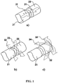
- FIG. 1 depicts a perspective view of the basic embodiment of the laterally unconstrained magnetic joint and its degrees of freedom.
- FIG. 2 shows perspective views with quarter sections of possible embodiments of the laterally unconstrained magnetic joint.
- FIG. 3 shows a perspective view of an example of a mirror mount embodiment with side section views of the possible laterally unconstrained magnetic joint embodiments.
- FIG. 4 shows perspective views of possible laterally unconstrained magnetic joint arrangements when used in mirror mount embodiments
- FIG. 1 depicts a perspective view of the basic embodiment of the laterally unconstrained magnetic joint (the “joint”).
- the joint consists of two components 21 and 22 interfacing each other: one component 22 having a flat interface surface, and the other component 21 having a convex interface surface.
- One embodiment of the joint comprises both components 21 and 22 made from a permanent magnet material magnetized in the same direction along the joint axis 31 .
- Another embodiment of the joint comprises one component made from a permanent magnet material and another from a ferromagnetic material. In both cases there is a magnetic force attracting the two components of the joint together along the joint axis 31 as shown in FIG. 1 . a ).
- the two components 21 and 22 of the joint are free to move laterally as shown in FIG. 1 . b ). While in most embodiments, the convex surface is expected to be spherical, any other continuous convex surface which allows desired range of tip-tilt motion is within the scope and spirit of this invention.
- the convex surface is expected to be spherical, any other continuous convex surface which allows desired range of tip-tilt motion is within the scope and spirit of this invention.
- the joint is free to articulate within all three rotational degrees of freedom, the two of which 34 and 35 are around the axes perpendicular to the joint axis 31 .
- the articulation 34 and 35 as shown in FIG. 1 . c ) is limited by the extent of the convex surface of the joint component 21 .
- FIG. 2 Examples of the joint embodiments are depicted in FIG. 2 .
- the basic joint embodiment as described in previous paragraphs is shown in FIG. 2 . a ).
- FIG. 2 . b depicts an example of embodiment where the joint interface surfaces are concave and convex with convex having a greater curvature so that lateral motion of the joint is permitted.
- this invention covers embodiments of any surface pair configuration that permits lateral motion between the two joint components 21 and 22 .
- the joint may have a component 23 as shown in FIG. 2 . c ) that improves bearing properties of the joint.
- Such component 23 may float between the two joint components 21 and 22 , be attached to one of the joint components, or be a surface coating of either or both joint components 21 and 22 .
- the joint may include ferromagnetic fluid (“ferrofluid”) 24 as shown in FIG. 2 . d ), which can be used to increase the magnetic force attracting the two joint components together, and/or improve the bearing properties by lubricating the interfacing surfaces of the joint.
- ferrofluid ferromagnetic fluid
- FIG. 3 An example of a mirror mount embodiment utilizing the laterally unconstrained magnetic joint (“mount”) is depicted in FIG. 3 .
- the mount would utilize three joints 11 arranged in any configuration other than a line, thus defining a plane with three points in space.
- all three joints 11 would interface a mirror, mirror mount, or any other type of payload 12 .
- This interface can have numerous embodiments, which are outside of the scope of this invention.
- an embodiment of an optical mount providing piston-tip-tilt functionality would have all three joints 11 interfacing an adjustor or linear actuator 13 ; and an embodiment of an optical mount providing tip-tilt functionality would have two joints 11 interfacing an adjustor or linear actuator 13 , while the third joint 11 will be statically attached to a reference point.
- Embodiment of adjustors and linear actuators 13 is outside of the scope of this invention and can be any combination of manual or motorized types including but not limited to: screws, fine-pitch screws, micrometers, differential screws, piezo actuators, leadscrews, ball-screws, roller screws, rack and pinions, chain drives, belt drives, hydraulic, pneumatic, voice-coils, linear drives, etc.
- FIG. 4 Examples of embodiments of an actuator 13 —joint 11 arrangements within a mount are shown in FIG. 4 .
- Equilateral triangle arrangement shown in FIG. 4 . a provides symmetrical mounting of the payload, equalizing the forces seen by joints 11 under uniform operating conditions. The drawback of equilateral arrangement is non-orthogonal actuation during adjustment.
- Orthogonal arrangement depicted in FIG. 4 . b ) is functionally equivalent to conventional tip-tilt mounts which utilize cone, groove, and flat constraint systems.
- Another embodiment shown in FIG. 4 . c ) is close functional equivalent of gimbal mounts, which minimize path length variation during adjustment.
Landscapes
- Physics & Mathematics (AREA)
- General Physics & Mathematics (AREA)
- Optics & Photonics (AREA)
- Engineering & Computer Science (AREA)
- General Engineering & Computer Science (AREA)
- Mechanical Engineering (AREA)
- Health & Medical Sciences (AREA)
- Environmental & Geological Engineering (AREA)
- Epidemiology (AREA)
- Public Health (AREA)
- Pivots And Pivotal Connections (AREA)
Abstract
Description
Claims (20)
Priority Applications (1)
| Application Number | Priority Date | Filing Date | Title |
|---|---|---|---|
| US16/125,758 US10830988B2 (en) | 2017-09-17 | 2018-09-09 | Laterally unconstrained magnetic joint for tip tilt and piston-tip-tilt mounts |
Applications Claiming Priority (2)
| Application Number | Priority Date | Filing Date | Title |
|---|---|---|---|
| US201762559610P | 2017-09-17 | 2017-09-17 | |
| US16/125,758 US10830988B2 (en) | 2017-09-17 | 2018-09-09 | Laterally unconstrained magnetic joint for tip tilt and piston-tip-tilt mounts |
Publications (2)
| Publication Number | Publication Date |
|---|---|
| US20190086634A1 US20190086634A1 (en) | 2019-03-21 |
| US10830988B2 true US10830988B2 (en) | 2020-11-10 |
Family
ID=65720132
Family Applications (1)
| Application Number | Title | Priority Date | Filing Date |
|---|---|---|---|
| US16/125,758 Active 2039-01-02 US10830988B2 (en) | 2017-09-17 | 2018-09-09 | Laterally unconstrained magnetic joint for tip tilt and piston-tip-tilt mounts |
Country Status (1)
| Country | Link |
|---|---|
| US (1) | US10830988B2 (en) |
Cited By (1)
| Publication number | Priority date | Publication date | Assignee | Title |
|---|---|---|---|---|
| US20240243647A1 (en) * | 2021-05-21 | 2024-07-18 | Lg Innotek Co., Ltd. | Actuator device |
Families Citing this family (5)
| Publication number | Priority date | Publication date | Assignee | Title |
|---|---|---|---|---|
| US10830988B2 (en) | 2017-09-17 | 2020-11-10 | Light Steering Technologies, Llc | Laterally unconstrained magnetic joint for tip tilt and piston-tip-tilt mounts |
| WO2020185195A1 (en) * | 2019-03-08 | 2020-09-17 | Light Steering Technologies, Llc | Magnetic joint and optical mount using the same |
| US10685771B1 (en) | 2019-03-08 | 2020-06-16 | Light Steering Technologies, Llc | Magnetic joint and optical mount using the same |
| EP3739384B1 (en) | 2019-05-17 | 2021-03-17 | Axis AB | A mount for an image capturing device |
| CN118590811B (en) * | 2024-05-16 | 2024-11-22 | 山东科技大学 | Quick reflector decoupling control method for voice coil motor |
Citations (14)
| Publication number | Priority date | Publication date | Assignee | Title |
|---|---|---|---|---|
| US5550669A (en) | 1993-04-19 | 1996-08-27 | Martin Marietta Corporation | Flexure design for a fast steering scanning mirror |
| US5821655A (en) * | 1996-01-30 | 1998-10-13 | Hitachi, Ltd. | Magnetic fluid bearing unit structure and motor having the same |
| US6566992B1 (en) | 1998-05-20 | 2003-05-20 | Claudio Vicentelli | Modules creating magnetic anchorage assemblies and relevant assemblies |
| US20030106230A1 (en) | 2001-12-10 | 2003-06-12 | Hennessey C. William | Parallel kinematic micromanipulator |
| US6856437B2 (en) | 2002-02-01 | 2005-02-15 | Terabeam Corporation | Fast steering mirror |
| JP2007032595A (en) | 2005-07-22 | 2007-02-08 | Oriental Motor Co Ltd | Magnet type floating joint |
| JP2008023076A (en) | 2006-07-21 | 2008-02-07 | Japan Aerospace Exploration Agency | Offset articulated structure having a branch arm mechanism for attaching and detaching a magnet |
| WO2008044229A1 (en) | 2006-10-10 | 2008-04-17 | Ofer Vexler | Artificial joint |
| US8043513B2 (en) | 2003-12-02 | 2011-10-25 | Adriatic Research Institute | Gimbal-less micro-electro-mechanical-system tip-tilt and tip-tilt-piston actuators and a method for forming the same |
| EP2816723A1 (en) | 2013-06-21 | 2014-12-24 | Cedrat Technologies | Tripod mechanism with piezoelectric actuators |
| US20150369418A1 (en) * | 2014-06-18 | 2015-12-24 | Helping Hands International Holdings Limited | Convertible stand/table |
| CN105587757A (en) | 2016-01-20 | 2016-05-18 | 东莞思谷数字技术有限公司 | Permanent magnet ball joint with posture sensing function and measuring method of permanent magnet ball joint |
| US20180095223A1 (en) | 2016-09-30 | 2018-04-05 | 3Sae Technologies, Inc. | Multi-axis relative positioning stage |
| US20190086634A1 (en) | 2017-09-17 | 2019-03-21 | Vladimir G. Krylov | Laterally unconstrained magnetic joint for tip-tilt and piston-tip-tilt mounts |
-
2018
- 2018-09-09 US US16/125,758 patent/US10830988B2/en active Active
Patent Citations (16)
| Publication number | Priority date | Publication date | Assignee | Title |
|---|---|---|---|---|
| US5550669A (en) | 1993-04-19 | 1996-08-27 | Martin Marietta Corporation | Flexure design for a fast steering scanning mirror |
| US5821655A (en) * | 1996-01-30 | 1998-10-13 | Hitachi, Ltd. | Magnetic fluid bearing unit structure and motor having the same |
| US6566992B1 (en) | 1998-05-20 | 2003-05-20 | Claudio Vicentelli | Modules creating magnetic anchorage assemblies and relevant assemblies |
| US20030106230A1 (en) | 2001-12-10 | 2003-06-12 | Hennessey C. William | Parallel kinematic micromanipulator |
| US6856437B2 (en) | 2002-02-01 | 2005-02-15 | Terabeam Corporation | Fast steering mirror |
| US8043513B2 (en) | 2003-12-02 | 2011-10-25 | Adriatic Research Institute | Gimbal-less micro-electro-mechanical-system tip-tilt and tip-tilt-piston actuators and a method for forming the same |
| JP2007032595A (en) | 2005-07-22 | 2007-02-08 | Oriental Motor Co Ltd | Magnet type floating joint |
| JP2008023076A (en) | 2006-07-21 | 2008-02-07 | Japan Aerospace Exploration Agency | Offset articulated structure having a branch arm mechanism for attaching and detaching a magnet |
| WO2008044229A1 (en) | 2006-10-10 | 2008-04-17 | Ofer Vexler | Artificial joint |
| EP2816723A1 (en) | 2013-06-21 | 2014-12-24 | Cedrat Technologies | Tripod mechanism with piezoelectric actuators |
| FR3007499A1 (en) | 2013-06-21 | 2014-12-26 | Cedrat Technologies | TRIPOD MECHANISM WITH PIEZOELECTRIC ACTUATORS |
| US20150369418A1 (en) * | 2014-06-18 | 2015-12-24 | Helping Hands International Holdings Limited | Convertible stand/table |
| CN105587757A (en) | 2016-01-20 | 2016-05-18 | 东莞思谷数字技术有限公司 | Permanent magnet ball joint with posture sensing function and measuring method of permanent magnet ball joint |
| US20180095223A1 (en) | 2016-09-30 | 2018-04-05 | 3Sae Technologies, Inc. | Multi-axis relative positioning stage |
| WO2018064462A1 (en) | 2016-09-30 | 2018-04-05 | 3Sae Technologies, Inc | Multi-axis relative positioning stage |
| US20190086634A1 (en) | 2017-09-17 | 2019-03-21 | Vladimir G. Krylov | Laterally unconstrained magnetic joint for tip-tilt and piston-tip-tilt mounts |
Non-Patent Citations (2)
| Title |
|---|
| C. Belly et al., "Long Stroke/High Resolution Tip Tilt Mechanism", Actuator, 14th International Conference on New Actuators, Jun. 2014, Bremen, Germany, 3 pages. |
| PCT Search Report and Written Opinion for PCT Application No. PCT/US2019/021286, dated Nov. 18, 2019, 15 pages. |
Cited By (1)
| Publication number | Priority date | Publication date | Assignee | Title |
|---|---|---|---|---|
| US20240243647A1 (en) * | 2021-05-21 | 2024-07-18 | Lg Innotek Co., Ltd. | Actuator device |
Also Published As
| Publication number | Publication date |
|---|---|
| US20190086634A1 (en) | 2019-03-21 |
Similar Documents
| Publication | Publication Date | Title |
|---|---|---|
| US10830988B2 (en) | Laterally unconstrained magnetic joint for tip tilt and piston-tip-tilt mounts | |
| US5004205A (en) | High-range and resolution determinate mount and positioner | |
| JP2024521393A (en) | Shape memory alloy actuator and method thereof | |
| US7188831B2 (en) | Flexure-type suspension system providing for three degrees of freedom and flexure-type positioning assembly based thereon | |
| US11385456B2 (en) | Device and method for positioning a moveable member, and a steerable mirror unit including such device | |
| US20220244564A1 (en) | Optical device with a supported flexure joint | |
| EP2235722B1 (en) | Stiffness compensation in opto-mechanical mechanisms | |
| CN110832212B (en) | Joint | |
| KR102499992B1 (en) | Support apparatus | |
| US9879974B2 (en) | Linear-motion stage | |
| JPH032810A (en) | High range and resolution defining mount and positioning device | |
| JP4375400B2 (en) | Reflector support mechanism | |
| CN112470053B (en) | Bimetal optical mounting seat | |
| EP3935426B1 (en) | Magnetic joint and optical mount using the same | |
| US10685771B1 (en) | Magnetic joint and optical mount using the same | |
| US20170030513A1 (en) | Linkage rod including limited-displacement flexible mechanism | |
| EP4441364A1 (en) | Sma actuator assembly | |
| US7086300B1 (en) | Large stroke linear motion flexural apparatus | |
| WO2002055971A1 (en) | Precision pointing system and method | |
| US7723672B1 (en) | Multi-position kinematic mount for optical sensors in stabilized platforms |
Legal Events
| Date | Code | Title | Description |
|---|---|---|---|
| FEPP | Fee payment procedure |
Free format text: ENTITY STATUS SET TO UNDISCOUNTED (ORIGINAL EVENT CODE: BIG.); ENTITY STATUS OF PATENT OWNER: SMALL ENTITY |
|
| FEPP | Fee payment procedure |
Free format text: ENTITY STATUS SET TO SMALL (ORIGINAL EVENT CODE: SMAL); ENTITY STATUS OF PATENT OWNER: SMALL ENTITY |
|
| STPP | Information on status: patent application and granting procedure in general |
Free format text: APPLICATION DISPATCHED FROM PREEXAM, NOT YET DOCKETED |
|
| STPP | Information on status: patent application and granting procedure in general |
Free format text: DOCKETED NEW CASE - READY FOR EXAMINATION |
|
| AS | Assignment |
Owner name: LIGHT STEERING TECHNOLOGIES, LLC, NEW HAMPSHIRE Free format text: ASSIGNMENT OF ASSIGNORS INTEREST;ASSIGNOR:KRYLOV, VLADIMIR G.;REEL/FRAME:049183/0677 Effective date: 20190307 |
|
| STPP | Information on status: patent application and granting procedure in general |
Free format text: NON FINAL ACTION MAILED |
|
| STPP | Information on status: patent application and granting procedure in general |
Free format text: RESPONSE TO NON-FINAL OFFICE ACTION ENTERED AND FORWARDED TO EXAMINER |
|
| STPP | Information on status: patent application and granting procedure in general |
Free format text: PUBLICATIONS -- ISSUE FEE PAYMENT VERIFIED |
|
| STCF | Information on status: patent grant |
Free format text: PATENTED CASE |
|
| FEPP | Fee payment procedure |
Free format text: SURCHARGE FOR LATE PAYMENT, SMALL ENTITY (ORIGINAL EVENT CODE: M2554); ENTITY STATUS OF PATENT OWNER: SMALL ENTITY |
|
| MAFP | Maintenance fee payment |
Free format text: PAYMENT OF MAINTENANCE FEE, 4TH YR, SMALL ENTITY (ORIGINAL EVENT CODE: M2551); ENTITY STATUS OF PATENT OWNER: SMALL ENTITY Year of fee payment: 4 |