US10830718B2 - Sensor for detecting immersion in F.O.G. or water - Google Patents
Sensor for detecting immersion in F.O.G. or water Download PDFInfo
- Publication number
- US10830718B2 US10830718B2 US16/031,245 US201816031245A US10830718B2 US 10830718 B2 US10830718 B2 US 10830718B2 US 201816031245 A US201816031245 A US 201816031245A US 10830718 B2 US10830718 B2 US 10830718B2
- Authority
- US
- United States
- Prior art keywords
- thermistor
- resistor
- water
- sensor
- period
- Prior art date
- Legal status (The legal status is an assumption and is not a legal conclusion. Google has not performed a legal analysis and makes no representation as to the accuracy of the status listed.)
- Active
Links
- XLYOFNOQVPJJNP-UHFFFAOYSA-N water Substances O XLYOFNOQVPJJNP-UHFFFAOYSA-N 0.000 title claims description 69
- 238000007654 immersion Methods 0.000 title 1
- 239000007788 liquid Substances 0.000 claims abstract description 42
- 239000000758 substrate Substances 0.000 claims abstract description 40
- 239000000615 nonconductor Substances 0.000 claims abstract description 16
- 230000008859 change Effects 0.000 claims description 18
- 239000003921 oil Substances 0.000 claims description 18
- RYGMFSIKBFXOCR-UHFFFAOYSA-N Copper Chemical group [Cu] RYGMFSIKBFXOCR-UHFFFAOYSA-N 0.000 claims description 16
- 238000000034 method Methods 0.000 claims description 16
- 238000004382 potting Methods 0.000 claims description 13
- 229910052802 copper Inorganic materials 0.000 claims description 11
- 239000010949 copper Substances 0.000 claims description 11
- 150000001875 compounds Chemical class 0.000 claims description 8
- 239000010797 grey water Substances 0.000 claims description 7
- 239000003208 petroleum Substances 0.000 claims description 5
- 150000001298 alcohols Chemical class 0.000 claims description 4
- 150000002632 lipids Chemical class 0.000 claims description 4
- 239000002184 metal Substances 0.000 claims description 4
- 229910052751 metal Inorganic materials 0.000 claims description 4
- 238000013517 stratification Methods 0.000 claims description 3
- 239000004020 conductor Substances 0.000 claims description 2
- PCHJSUWPFVWCPO-UHFFFAOYSA-N gold Chemical compound [Au] PCHJSUWPFVWCPO-UHFFFAOYSA-N 0.000 claims description 2
- 239000010931 gold Substances 0.000 claims description 2
- 229910052737 gold Inorganic materials 0.000 claims description 2
- 230000005611 electricity Effects 0.000 claims 6
- 239000004519 grease Substances 0.000 description 12
- 238000012360 testing method Methods 0.000 description 11
- 238000010438 heat treatment Methods 0.000 description 10
- 238000005538 encapsulation Methods 0.000 description 6
- 238000002474 experimental method Methods 0.000 description 6
- 239000000203 mixture Substances 0.000 description 6
- 239000004593 Epoxy Substances 0.000 description 5
- 235000013305 food Nutrition 0.000 description 5
- 239000000463 material Substances 0.000 description 5
- 239000000523 sample Substances 0.000 description 5
- 239000004831 Hot glue Substances 0.000 description 4
- 238000009434 installation Methods 0.000 description 4
- 239000012212 insulator Substances 0.000 description 4
- 239000004033 plastic Substances 0.000 description 4
- 238000007710 freezing Methods 0.000 description 3
- 230000008014 freezing Effects 0.000 description 3
- 229910001120 nichrome Inorganic materials 0.000 description 3
- 229920001296 polysiloxane Polymers 0.000 description 3
- 238000005086 pumping Methods 0.000 description 3
- 239000002910 solid waste Substances 0.000 description 3
- 238000009835 boiling Methods 0.000 description 2
- 239000000356 contaminant Substances 0.000 description 2
- 238000013480 data collection Methods 0.000 description 2
- 238000013461 design Methods 0.000 description 2
- DMBHHRLKUKUOEG-UHFFFAOYSA-N diphenylamine Chemical compound C=1C=CC=CC=1NC1=CC=CC=C1 DMBHHRLKUKUOEG-UHFFFAOYSA-N 0.000 description 2
- 239000003925 fat Substances 0.000 description 2
- 238000004519 manufacturing process Methods 0.000 description 2
- 238000012986 modification Methods 0.000 description 2
- 230000004048 modification Effects 0.000 description 2
- 235000019645 odor Nutrition 0.000 description 2
- 230000008569 process Effects 0.000 description 2
- UAOUIVVJBYDFKD-XKCDOFEDSA-N (1R,9R,10S,11R,12R,15S,18S,21R)-10,11,21-trihydroxy-8,8-dimethyl-14-methylidene-4-(prop-2-enylamino)-20-oxa-5-thia-3-azahexacyclo[9.7.2.112,15.01,9.02,6.012,18]henicosa-2(6),3-dien-13-one Chemical compound C([C@@H]1[C@@H](O)[C@@]23C(C1=C)=O)C[C@H]2[C@]12C(N=C(NCC=C)S4)=C4CC(C)(C)[C@H]1[C@H](O)[C@]3(O)OC2 UAOUIVVJBYDFKD-XKCDOFEDSA-N 0.000 description 1
- 239000000853 adhesive Substances 0.000 description 1
- 230000001070 adhesive effect Effects 0.000 description 1
- 230000008901 benefit Effects 0.000 description 1
- 239000012459 cleaning agent Substances 0.000 description 1
- 230000007423 decrease Effects 0.000 description 1
- 230000001934 delay Effects 0.000 description 1
- 238000010586 diagram Methods 0.000 description 1
- 238000005516 engineering process Methods 0.000 description 1
- 238000005530 etching Methods 0.000 description 1
- 235000013312 flour Nutrition 0.000 description 1
- 239000012530 fluid Substances 0.000 description 1
- 230000017525 heat dissipation Effects 0.000 description 1
- 239000012943 hotmelt Substances 0.000 description 1
- 239000010720 hydraulic oil Substances 0.000 description 1
- 239000005457 ice water Substances 0.000 description 1
- 238000010943 off-gassing Methods 0.000 description 1
- 238000004806 packaging method and process Methods 0.000 description 1
- 239000002985 plastic film Substances 0.000 description 1
- 229920003223 poly(pyromellitimide-1,4-diphenyl ether) Polymers 0.000 description 1
- 238000011084 recovery Methods 0.000 description 1
- 238000012552 review Methods 0.000 description 1
- 238000005070 sampling Methods 0.000 description 1
- 239000007787 solid Substances 0.000 description 1
- 125000006850 spacer group Chemical group 0.000 description 1
- 238000003860 storage Methods 0.000 description 1
- 239000000126 substance Substances 0.000 description 1
- 238000012546 transfer Methods 0.000 description 1
- 239000002699 waste material Substances 0.000 description 1
- 239000002351 wastewater Substances 0.000 description 1
Images


Classifications
-
- G—PHYSICS
- G01—MEASURING; TESTING
- G01N—INVESTIGATING OR ANALYSING MATERIALS BY DETERMINING THEIR CHEMICAL OR PHYSICAL PROPERTIES
- G01N25/00—Investigating or analyzing materials by the use of thermal means
- G01N25/18—Investigating or analyzing materials by the use of thermal means by investigating thermal conductivity
-
- B—PERFORMING OPERATIONS; TRANSPORTING
- B01—PHYSICAL OR CHEMICAL PROCESSES OR APPARATUS IN GENERAL
- B01D—SEPARATION
- B01D17/00—Separation of liquids, not provided for elsewhere, e.g. by thermal diffusion
- B01D17/02—Separation of non-miscible liquids
- B01D17/0208—Separation of non-miscible liquids by sedimentation
-
- B—PERFORMING OPERATIONS; TRANSPORTING
- B01—PHYSICAL OR CHEMICAL PROCESSES OR APPARATUS IN GENERAL
- B01D—SEPARATION
- B01D17/00—Separation of liquids, not provided for elsewhere, e.g. by thermal diffusion
-
- B—PERFORMING OPERATIONS; TRANSPORTING
- B01—PHYSICAL OR CHEMICAL PROCESSES OR APPARATUS IN GENERAL
- B01D—SEPARATION
- B01D17/00—Separation of liquids, not provided for elsewhere, e.g. by thermal diffusion
- B01D17/12—Auxiliary equipment particularly adapted for use with liquid-separating apparatus, e.g. control circuits
-
- C—CHEMISTRY; METALLURGY
- C02—TREATMENT OF WATER, WASTE WATER, SEWAGE, OR SLUDGE
- C02F—TREATMENT OF WATER, WASTE WATER, SEWAGE, OR SLUDGE
- C02F1/00—Treatment of water, waste water, or sewage
- C02F1/40—Devices for separating or removing fatty or oily substances or similar floating material
-
- G—PHYSICS
- G01—MEASURING; TESTING
- G01F—MEASURING VOLUME, VOLUME FLOW, MASS FLOW OR LIQUID LEVEL; METERING BY VOLUME
- G01F23/00—Indicating or measuring liquid level or level of fluent solid material, e.g. indicating in terms of volume or indicating by means of an alarm
- G01F23/22—Indicating or measuring liquid level or level of fluent solid material, e.g. indicating in terms of volume or indicating by means of an alarm by measuring physical variables, other than linear dimensions, pressure or weight, dependent on the level to be measured, e.g. by difference of heat transfer of steam or water
- G01F23/24—Indicating or measuring liquid level or level of fluent solid material, e.g. indicating in terms of volume or indicating by means of an alarm by measuring physical variables, other than linear dimensions, pressure or weight, dependent on the level to be measured, e.g. by difference of heat transfer of steam or water by measuring variations of resistance of resistors due to contact with conductor fluid
- G01F23/246—Indicating or measuring liquid level or level of fluent solid material, e.g. indicating in terms of volume or indicating by means of an alarm by measuring physical variables, other than linear dimensions, pressure or weight, dependent on the level to be measured, e.g. by difference of heat transfer of steam or water by measuring variations of resistance of resistors due to contact with conductor fluid thermal devices
- G01F23/247—Indicating or measuring liquid level or level of fluent solid material, e.g. indicating in terms of volume or indicating by means of an alarm by measuring physical variables, other than linear dimensions, pressure or weight, dependent on the level to be measured, e.g. by difference of heat transfer of steam or water by measuring variations of resistance of resistors due to contact with conductor fluid thermal devices for discrete levels
- G01F23/248—Constructional details; Mounting of probes
-
- G—PHYSICS
- G01—MEASURING; TESTING
- G01N—INVESTIGATING OR ANALYSING MATERIALS BY DETERMINING THEIR CHEMICAL OR PHYSICAL PROPERTIES
- G01N33/00—Investigating or analysing materials by specific methods not covered by groups G01N1/00 - G01N31/00
- G01N33/18—Water
- G01N33/1826—Water organic contamination in water
- G01N33/1833—Oil in water
-
- H—ELECTRICITY
- H05—ELECTRIC TECHNIQUES NOT OTHERWISE PROVIDED FOR
- H05K—PRINTED CIRCUITS; CASINGS OR CONSTRUCTIONAL DETAILS OF ELECTRIC APPARATUS; MANUFACTURE OF ASSEMBLAGES OF ELECTRICAL COMPONENTS
- H05K1/00—Printed circuits
- H05K1/02—Details
- H05K1/09—Use of materials for the conductive, e.g. metallic pattern
-
- H—ELECTRICITY
- H05—ELECTRIC TECHNIQUES NOT OTHERWISE PROVIDED FOR
- H05K—PRINTED CIRCUITS; CASINGS OR CONSTRUCTIONAL DETAILS OF ELECTRIC APPARATUS; MANUFACTURE OF ASSEMBLAGES OF ELECTRICAL COMPONENTS
- H05K1/00—Printed circuits
- H05K1/18—Printed circuits structurally associated with non-printed electric components
- H05K1/181—Printed circuits structurally associated with non-printed electric components associated with surface mounted components
-
- H—ELECTRICITY
- H05—ELECTRIC TECHNIQUES NOT OTHERWISE PROVIDED FOR
- H05K—PRINTED CIRCUITS; CASINGS OR CONSTRUCTIONAL DETAILS OF ELECTRIC APPARATUS; MANUFACTURE OF ASSEMBLAGES OF ELECTRICAL COMPONENTS
- H05K5/00—Casings, cabinets or drawers for electric apparatus
- H05K5/06—Hermetically-sealed casings
- H05K5/064—Hermetically-sealed casings sealed by potting, e.g. waterproof resin poured in a rigid casing
-
- C—CHEMISTRY; METALLURGY
- C02—TREATMENT OF WATER, WASTE WATER, SEWAGE, OR SLUDGE
- C02F—TREATMENT OF WATER, WASTE WATER, SEWAGE, OR SLUDGE
- C02F2103/00—Nature of the water, waste water, sewage or sludge to be treated
- C02F2103/32—Nature of the water, waste water, sewage or sludge to be treated from the food or foodstuff industry, e.g. brewery waste waters
-
- C—CHEMISTRY; METALLURGY
- C02—TREATMENT OF WATER, WASTE WATER, SEWAGE, OR SLUDGE
- C02F—TREATMENT OF WATER, WASTE WATER, SEWAGE, OR SLUDGE
- C02F2209/00—Controlling or monitoring parameters in water treatment
- C02F2209/42—Liquid level
-
- H—ELECTRICITY
- H05—ELECTRIC TECHNIQUES NOT OTHERWISE PROVIDED FOR
- H05K—PRINTED CIRCUITS; CASINGS OR CONSTRUCTIONAL DETAILS OF ELECTRIC APPARATUS; MANUFACTURE OF ASSEMBLAGES OF ELECTRICAL COMPONENTS
- H05K2201/00—Indexing scheme relating to printed circuits covered by H05K1/00
- H05K2201/03—Conductive materials
- H05K2201/0332—Structure of the conductor
- H05K2201/0335—Layered conductors or foils
- H05K2201/0338—Layered conductor, e.g. layered metal substrate, layered finish layer, layered thin film adhesion layer
-
- H—ELECTRICITY
- H05—ELECTRIC TECHNIQUES NOT OTHERWISE PROVIDED FOR
- H05K—PRINTED CIRCUITS; CASINGS OR CONSTRUCTIONAL DETAILS OF ELECTRIC APPARATUS; MANUFACTURE OF ASSEMBLAGES OF ELECTRICAL COMPONENTS
- H05K2201/00—Indexing scheme relating to printed circuits covered by H05K1/00
- H05K2201/10—Details of components or other objects attached to or integrated in a printed circuit board
- H05K2201/10007—Types of components
- H05K2201/10022—Non-printed resistor
-
- H—ELECTRICITY
- H05—ELECTRIC TECHNIQUES NOT OTHERWISE PROVIDED FOR
- H05K—PRINTED CIRCUITS; CASINGS OR CONSTRUCTIONAL DETAILS OF ELECTRIC APPARATUS; MANUFACTURE OF ASSEMBLAGES OF ELECTRICAL COMPONENTS
- H05K2201/00—Indexing scheme relating to printed circuits covered by H05K1/00
- H05K2201/10—Details of components or other objects attached to or integrated in a printed circuit board
- H05K2201/10007—Types of components
- H05K2201/10151—Sensor
-
- H—ELECTRICITY
- H05—ELECTRIC TECHNIQUES NOT OTHERWISE PROVIDED FOR
- H05K—PRINTED CIRCUITS; CASINGS OR CONSTRUCTIONAL DETAILS OF ELECTRIC APPARATUS; MANUFACTURE OF ASSEMBLAGES OF ELECTRICAL COMPONENTS
- H05K2201/00—Indexing scheme relating to printed circuits covered by H05K1/00
- H05K2201/10—Details of components or other objects attached to or integrated in a printed circuit board
- H05K2201/10007—Types of components
- H05K2201/10196—Variable component, e.g. variable resistor
Definitions
- Oil, grease and solid waste contaminant removal or recovery systems are well known in the prior art. Over the past thirty years there has been a steady move towards requiring food handling facilities to have systems for servicing kitchen grease and solid waste bearing water flows. Sewer system lines can become clogged from the fats, oil and grease waste materials (hereinafter referred to as “F.O.G.”) put into the sewer system from food handling facilities. This has led more and more sewer authorities to implement fats, oils and grease control programs. These programs regulate food handling facilities and the manner in which they process F.O.G.s. The object of many of these programs is to ensure that food handling facilities remove as much of the F.O.G. as possible from the effluent flow, thereby releasing only grey water to the sewer system.
- F.O.G. fats, oil and grease waste materials
- Active separators remove F.O.G. from the effluent, typically by some skimming operation. Skimming when skimming is required and not skimming when it is not required has been an issue for the art.
- the traditional methodology is simply to use a timer that turns on the skimming apparatus at a certain time of day and runs it for a certain period, providing the user only with control as to the time of day and duration. For installations that have very regular schedules, this may be sufficient. However, for other installations that operate on less than a regular schedule, problems can arise. Schedule variations can be as simple as the differences between weekday and weekend operation. Also, for installations such as school cafeterias that do not operate during the summer, F.O.G.
- thermocouples can be expensive and provide other challenges.
- the effluent in which the sensor is immersed can be corrosive, since it includes a wide range of items that are discharged through kitchen sinks, including cleaning agents and bleaches. The sensor must be able to withstand such corrosive attacks in order to give reliable information over time.
- the kitchen effluent may have a range of temperatures, a range that can vary over time even for a single installation.
- a temperature based sensor such as a thermistor will react differently than when a pitcher of ice water is drained. Practical applications may involve battery power, so reducing power consumption is preferred in order to lengthen battery life.
- a thermally conductive substrate has a resistor mounted to it with two leads to enable a current to be passed through the resistor to generate heat.
- a thermistor is also mounted to the substrate with two leads to enable a current to be passed through the thermistor to generate a datum indicative of thermistor temperature.
- An electrical insulator encapsulates the resistor, the thermistor and part of the thermally conductive substrate. A remainder of the thermally conductive substrate may extend beyond the electrical insulator to provide a thermal path from the resistor and thermistor to a liquid in which the apparatus may be immersed in some embodiments.
- the leads of the resistor and thermistor are electrically connected to electrically conductive regions of the thermally conductive substrate.
- One lead of the resistor and one lead of the thermistor may both be electrically connected to a common electrically conductive region of the thermally conductive substrate. That region may be connected to ground.
- the substrate may be a printed circuit board with a metal face, such as copper.
- the copper may be coated with gold, particularly.
- the remainder of the thermally conductive substrate may extend beyond the electrical insulator.
- the electrical insulator may be a potting compound.
- the leads of the thermistor may be connected to a data gathering unit that samples the data indicative of thermistor temperature over a period of at least forty seconds and computes a ratio of temperature rise.
- the denominator of the ratio is the temperature rise in the first twenty seconds and the numerator of the ratio is the temperature rise in the sampled period after the first twenty seconds.
- a thermal paste may be located between the thermally conductive substrate and the resistor and thermistor.
- the invention may also be considered as a separator for separating F.O.G. from an effluent that contains F.O.G. and water.
- the separator includes a tank, an inlet to the tank for receiving effluent that contains F.O.G. and water and an outlet to allow grey water to leave the tank, the tank having a size to enable stratification to form a layer of F.O.G. in the tank on top of water in the tank.
- a sensor apparatus is located at a location within the tank for discriminating between F.O.G. and water at the location in the tank.
- the sensor apparatus includes a thermally conductive substrate, a resistor mounted to the thermally conductive substrate with two leads to enable a current to be passed through the resistor to generate heat, and a thermistor mounted to the substrate with two leads to enable a current to be passed through the thermistor to generate a datum indicative of thermistor temperature.
- An electrical insulator encapsulates the resistor, the thermistor and at least part of the thermally conductive substrate. A remainder of the thermally conductive substrate may extend beyond the electrical insulator to provide a thermal path from the resistor and thermistor to a liquid in the tank. Differing voltages in the thermistor can be sensed to determine if the sensor apparatus is surrounded by air, F.O.G. or water.
- the invention may also be considered as a method of discriminating between liquids having differing thermal conductivities.
- the method includes positioning a sensor at a location where it may be exposed to the liquids having differing thermal conductivities, the sensor including a thermal path from a heater and a thermistor.
- the thermal path may have a thermal conductivity comparable to copper.
- the method also includes applying heat to the sensor with the heater, reading data from the thermistor indicative of thermistor temperature repeatedly over a period of at least forty seconds, and computing a ratio of temperature rise, the denominator of the ratio being the temperature rise in the first twenty seconds of the data gathering period and the numerator of the ratio being the temperature rise in the data gathering period after the first twenty seconds.
- the computation may include taking an area under the curve of the temperature versus time.
- the computation may include sampling a selected temperature rise to determine if the sensor is in one liquid or the other.
- the liquids having differing thermal conductivities may be various liquids including lipids and water; petroleum oils and water; and concentrated alcohols and water.
- FIG. 1 is a top schematic view of a sensor in accordance with an embodiment of the invention before its encapsulation
- FIG. 2 is a perspective view of a sensor in accordance with an embodiment of the invention.
- FIG. 3 is a perspective view of a sensor in accordance with an embodiment of the invention as immersed in a test liquid;
- FIG. 4 is a graph of temperature rise over time for oil and water
- FIG. 5 is a graph of temperature rise over time for oil and water using a particular thermistor at a 5 volt heater voltage
- FIG. 6 is a graph of temperature rise over time for oil and water using a particular thermistor at a 4 volt heater voltage
- FIG. 7 is a graph of temperature rise over time for oil and water using a particular thermistor at a 4.5 volt heater voltage
- FIG. 8 is a graph of temperature rise over time for oil and water using a particular thermistor at a 6 volt heater voltage
- FIG. 9 is a graph of temperature rise over time for oil and water using a particular thermistor at a 7 volt heater voltage
- FIGS. 10A and 10B are raw data test curves for oil and water in similar temperature ranges
- FIG. 11 is a graph of temperature rise over time for oil and water using a particular thermistor at a 5 volt heater voltage starting at a colder temperature;
- FIG. 12 is a graph of temperature rise over time for oil and water using a particular thermistor at a 5 volt heater voltage starting at a warmer temperature;
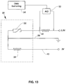
- FIG. 13 is a schematic circuit diagram showing an embodiment of the sensor in a data-gathering mode
- FIG. 14 a is a view of another embodiment of PC board usable in the invention.
- FIG. 14 b is a partial side view of the sensor unit made with the PC board embodiment shown in FIG. 14 ;
- FIG. 14 c is perspective view of a jig for receiving the PC board embodiment shown in FIG. 14 , partially broken away;
- FIG. 15 is a graph of temperature rise over time for oil and water using the PC board embodiment shown in FIGS. 14 a - c;
- FIG. 16 is a view of another embodiment with a tape form of encapsulation
- FIG. 17 shows a stage of assembly of yet another form of encapsulation of a sensor unit
- FIG. 18 show the final sensor unit of the embodiment of FIG. 17 ;
- FIG. 19 shows a skimmer apparatus equipped with a sensor in accordance with an embodiment of the invention
- FIG. 20 shows a grease trap equipped with a sensor in accordance with an embodiment of the invention
- FIG. 21 shows an alternate embodiment of a sensor
- FIG. 22 shows a graph of temperature versus time for various FOG and water combinations as sensed using the sensor of FIG. 21 .
- a contact sensor 20 has a surface mounted resistor 24 and thermistor 22 on a small printed circuit board 26 .
- the board 26 is shown with a top surface covered with copper. Etchings 27 break electrical conductivity between portions of the board where one of the leads of the resistor 24 and thermistor 22 are mounted. However, each of resistor 24 and thermistor 22 is attached to a zone 29 that can serve as a common or ground connection 44 .
- Connector tabs 40 , 42 , and 44 enable connection to wires 48 shown in FIG. 2 .
- Tab 40 is connected to a battery or other voltage source (not shown).
- Tab 42 is connected to data gathering equipment (not shown, but discussed below).
- a potting compound 28 covers the resistor and thermistor on the printed circuit board.
- a suitable potting compound is a potting epoxy.
- a heat sink segment 30 of the board is left exposed and not covered by the potting compound.
- the board 26 can use a 24 ohm resistor 24 run at 3V in order to generate the heat.
- the specific design of the thermistor 22 does not matter, as long as its range allows the reading of temperatures decently accurately over a large range of temperatures, ideally from just under the freezing point of water up to close to its boiling point.
- a particular embodiment of the sensor uses an 8 pin AD590 Temperature Transducer (available from Analog Devices, One Technology Way, Norwood, Mass.) as the thermistor 22 and a 24 ohm resistor 24 . Both have a layer of thermal paste between them and the copper on the printed circuit board to enhance thermal conductivity between them and the copper on the printed circuit board. They are glued to the copper using Loctite 401 .
- the data gathering equipment 54 can use an iOS ESP8266 WiFi Module attached to an analog-to-digital converter 52 that digitizes the signal on tab 42 transmitted on lead 48 .
- the ESP8266 WiFi Module has integrated TCP/IP protocol stack that can give a microcontroller access to a WiFi network to communicate the data points over the internet to a data collection unit. In a test set-up the internet data collection unit used allows for a maximum of one data point every 15 seconds, so to ensure no data was lost, data was sent only every 20 seconds. Other data gathering systems can collect data at different rates. The algorithm was set to read an initial temperature, turn on the internal heating element (the resistor) and take a temperature reading every 20 seconds with the thermistor for a minute. Afterwards the heating element was turned off and four additional readings were taken.
- the senor 20 will be immersed in a liquid mixture that includes liquids having differing thermal conductivities, particularly immiscible liquids that stratify, so that each liquid is more or less separated from the other.
- stratified liquid is an effluent containing F.O.G. and water that are separated in a grease interceptor or grease trap.
- the sensor may also be used in other applications, such as lipids and water, petroleum oils and water, concentrated alcohols and water, etc.
- the sensor gauges the relative thermal conductance of the media adjacent to the resistor-thermistor components section of the circuit.
- the sensor can discern between petroleum oil and water layers in a container used in industrial site for separating and capturing hydraulic oils spilled into an effluent stream.
- An electrical voltage is applied to the leads of the resistor 24 , causing it to generate heat that is conducted through the printed circuit board 26 and out the heat sink segment 30 into the surrounding liquid.
- Heat also can be conducted through the potting compound or other electrical insulator that is used to encapsulate the resistor and thermistor. Initially, much of the heat will be contained in the apparatus, but over time the surrounding liquid also heats up. However the rate of heating varies depending on which liquid surrounds the sensor 20 . Water conducts heat better than F.O.G. does, so if the sensor is immersed in water, the heat conducts further and faster than if the sensor is immersed in F.O.G.
- a basic sensor 20 was created using a piece of copper 26 with a slit 27 cut in it for the AD 590 thermistor 22 to sit in. It was then electrically insulated with kapton tape and wound with Nichrome wire to be used as the heater 24 . Those components were covered in a two-part epoxy in order to water- and F.O.G.-proof the unit, hold everything in place, and thermally insulate most of the unit except for the exposed probe end 30 of the copper. The probe end 30 lets heat escape in order to test how fast the surrounding media can absorb it. By keeping the exposed area relatively small, the heater also can stay small.
- the Nichrome wire segment has a resistance of approximately 45 ohm and it is run at 5V dc, giving a power output of approximately 0.56 watt.
- 5 seconds were allowed to elapse before turning on the power supply to the nichrome wire to ensure that data would be captured correctly.
- the order of events during the experiment is as follows:
- the probe temperature increased by 15 degrees Celsius in F.O.G. and between 6 and 10 degrees Celsius in water.
- FIG. 14 a shows another printed circuit board 126 design usable in the invention.
- the wire layout has 3 traces in order to minimize thermal mass and size.
- This embodiment has a common ground for both the heating element and the thermistor but a common voltage could be used for both, with separate grounds.
- the common ground version for the thermistor and resistor can operate on separate voltages.
- the common voltage variation might be better for production in combination with a transistor to power on and off the heater, since transistors usually only work on the ground line as a higher voltage is typically needed to open the gate terminal.
- This embodiment uses a 24 ohm resistor for the heating element on 3V giving 0.375 watts of heat, which gives a discernible difference between curves for F.O.G. and water. Assuming the sensor will eventually run off of 12V, a 380 ohm resistor would be a good choice to get around the same wattage.
- This embodiment has an NTC thermistor with 100 k ohms at room temperature. A 100 k ohm resistor gives a high accuracy at room temperature range but not at high temperatures. When used with a 50 k ohms resistor, the sensor seems to be able to read all relevant temperature ranges. This embodiment provides a low profile, ease of assembly, and low thermistor cost.
- FIG. 14 b shows the encapsulated PCB with the exposed heat sink segment 230 .
- a hot glue can be used to act as an electrical insulator. The hot glue seems to easily conduct the heat to a much larger surface area, allowing for an overall cooler sensor and is not the thermal insulator that was expected.
- FIG. 14 c shows a jig or housing 300 for the PCB 325 .
- the jig holds the PCB with its attached resistor and thermistor in place during encapsulation with a hot glue or potting compound. This allows for enough space to pot the board and mounted components without risking the possibility of having a lack of potting material or air bubbles.
- the board 326 can be positively held in place so that there is no way it is put in wrong and having it misaligned.
- the PCB 326 is held in place with spacers 328 .
- the graph of FIG. 15 shows what the thermistor reads at various temperatures.
- the optimal measuring range is where the line graphed is relatively flat.
- the 100 k ohm line is more accurate in the lower temperatures and even below freezing while the 50 k ohm line becomes accurate toward freezing and stays accurate for longer.
- a suitable potting material is 823C Epoxy from MG Chemicals.
- the epoxy is chemically resistant, waterproof, and can cure at room temperature.
- the potting compound performs a few basic functions in the sensor. It holds everything in place, electrically insulates the traces, and makes it so that the environment cannot harm the sensor. Lastly, it helps act as a thermal insulator and therefore decreases the thermal leakage in undesired directions.
- FIG. 16 uses an encapsulation tape 370 instead of (or perhaps in addition to) a potting compound or hot melt.
- the PCB is sandwiched within layers of VHB tape or similar adhesive.
- VHB tape is available from 3M, St. Paul, Minn.
- An advantage of the VHB embodiment is the ease of assembly and not having to wait for any curing process before further assembly, packaging, or shipping. It might be possible to have the probe end inside and to probe through the VHB, similar to what was done with the hot glue on the above experiment.
- FIGS. 17 and 18 Another encapsulation technique is shown in FIGS. 17 and 18 .
- This uses a tube 440 and a sleeve-like cap 460 .
- a slit in the tube pipe and a groove in the cap hold the PCB 426 in place.
- Silicone is put into the tube 440 with the PCB to seal the base of the PCB into the tube 440 and provide a seal for potting.
- the cap 460 is applied. After the Silicone cures, epoxy poured into the cavity in the end of the tube 440 and cap 460 to fill it the space from the silicone to the brim of the cap 460 .
- the sensor unit is deployed in a liquid, and the task is to determine if the liquid is of one layer of stratification or another.
- Other ways to use the data can also be used to make this determination. For example, the area under the curves of the data depicted in the graphs for a given period of time can be computed and compared with other collected data, such as stored data. Averages of the temperature values over the set period can also be computed and such comparisons made from the computed averages.
- An embodiment provides the sensors positioned at differing heights in a grease trap tank or other passive separator, such as Thermaco's Trapzilla® grease trap, shown in FIG. 20 .
- the grease trap includes a tank 60 having a conically shaped bottom 62 .
- a divider 63 divides the tank 60 into an upper chamber and a lower chamber.
- a hole (not shown in FIG. 20 ) near an upper part of the divider 63 allows F.O.G. to rise into the upper chamber.
- An inlet invert 64 in the tank receives incoming waste water that includes F.O.G., while an outlet invert 66 removes grey water from the tank.
- a lid 68 covers the tank.
- a pipe 70 extends through the lid, upper chamber, and the divider 63 for pumping solid waste out of the lower chamber, as well as the F.O.G. Most of the grey water passes through the outlet invert 66 during normal kitchen effluent flows.
- Rods 12 and 14 are supported by lid 68 and each have a sensor as described above near their bottoms.
- the remainder of the column lengths of the rods can be made up of conduit for carrying wires to the top and for supporting the sensor at the correct depth within the tank.
- Rods 12 , 14 are of differing length, and the sensors each indicate whether water or FOG is present at its height within the tank. When the F.O.G. capacity of the tank is approaching, attached electronics can generate a signal to call for pumping the F.O.G. from the tank.
- the longer rod 14 preferably terminates at the level where the tank is considered to be 75% full of F.O.G., and the shorter one is at the 50% level. Other locations in the tank can be used.
- the sensors can also be used with active separators that do skimming, such as Thermaco's Big Dipper® separators shown in FIG. 19 .
- skimming includes other ways of taking the F.O.G. off the top, including opening spouts that drain the F.O.G. (see U.S. Pat. No. 7,186,346 for examples), pumping the F.O.G. (see U.S. Pat. No. 6,517,715 for an example), or other active methods.
- the thermistors are useful on the active F.O.G. removal units, such as the Big Dipper.
- active unit includes a container 530 that receives effluent from an inlet 531 and allows the flow rate to slow sufficiently that a F.O.G. mat 38 can collect on top of the grey water 540 .
- the active unit has one or more rotating disks 532 formed of a plastic or like material to which F.O.G. contaminants are attracted. Typically, the rotation of the disk is in an at least partially immersed condition, which allows the F.O.G.
- FIG. 21 shows an alternate embodiment of a sensor.
- two levels of a liquid can be evaluated with a single sensor.
- the sensor as shown is intended to be mounted with its longer sides extending vertically in the container for the liquids. That positions the two thermistors and two resistors at differing heights, so that the data available is more extensive.
- the resistors, thermistors and connection traces are printed on a sheet of a plastic material and covered by an electrical insulator in the form of another sheet of plastic. The sheets are thin, so the heat flows out from the resistor over a thermal path through the surrounding plastic to the surrounding liquid.
- the thermistor temperature is the result of conduction through the materials between it and the resistor, but with the heat diverted to the surrounding liquid affecting how much heat travels to the thermistor. The greater the heat transfer through the plastic sheets to the surrounding liquid, the lower the temperature of the thermistor will be.
- the resistors can both be supplied with current using a common conductor and a common ground.
- the thermistors also share the same common ground but each has a separate supply current, so that each thermistor can be read individually.
- FIG. 22 shows a graph of temperature versus time for various FOG and water combinations as sensed using the sensor of FIG. 21 .
- various types of liquid mixtures that may be encountered in a grease trap or an active skimmer can be sensed, and the data collected can determine which of the types of mixtures are present.
- These mixtures include FOG (oil), room temperature water, water containing flour, water emulsified with FOG in a mixture of 66% water, and water emulsified with FOG in a mixture of 50% water.
Abstract
Description
-
- t=0: start recording, ensuring that everything is transmitting properly
- t=5 seconds: turn on heating element
- t=95 seconds: turn off heating element
- t=185 seconds: stop recording
| Water | F.O.G. | ||
| D1 | D2 | % | D1 | D2 | % | ||
| 53 | 12 | 22.64% | 44 | 24 | 54.55% | ||
| 51 | 11 | 21.57% | 42 | 22 | 52.38% | ||
| 50 | 10 | 20.00% | 41 | 20 | 48.78% | ||
| 47 | 10 | 21.28% | 40 | 19 | 47.50% | ||
| 45 | 10 | 22.22% | 38 | 20 | 52.63% | ||
| 44 | 9 | 20.45% | 36 | 19 | 52.78% | ||
| 43 | 9 | 20.93% | 36 | 18 | 50.00% | ||
| 43 | 9 | 20.93% | 34 | 18 | 52.94% | ||
| 42 | 9 | 21.43% | 34 | 17 | 50.00% | ||
| 40 | 10 | 25.00% | |||||
| 41 | 7 | 17.07% | |||||
| 40 | 8 | 20.00% | |||||
| 39 | 8 | 20.51% | |||||
| 39 | 8 | 20.51% | |||||
| 38 | 7 | 18.42% | |||||
| 39 | 7 | 17.95% | |||||
| 36 | 8 | 22.22% | |||||
| 37 | 7 | 18.92% | |||||
| 36 | 7 | 19.44% | |||||
| 37 | 7 | 18.92% | |||||
| 37 | 7 | 18.92% | |||||
| 33 | 6 | 18.18% | |||||
| 33 | 5 | 15.15% | |||||
| 32 | 5 | 15.63% | |||||
Claims (20)
Priority Applications (1)
| Application Number | Priority Date | Filing Date | Title |
|---|---|---|---|
| US16/031,245 US10830718B2 (en) | 2017-07-10 | 2018-07-10 | Sensor for detecting immersion in F.O.G. or water |
Applications Claiming Priority (3)
| Application Number | Priority Date | Filing Date | Title |
|---|---|---|---|
| US201762530437P | 2017-07-10 | 2017-07-10 | |
| US201762565541P | 2017-09-29 | 2017-09-29 | |
| US16/031,245 US10830718B2 (en) | 2017-07-10 | 2018-07-10 | Sensor for detecting immersion in F.O.G. or water |
Publications (2)
| Publication Number | Publication Date |
|---|---|
| US20190137423A1 US20190137423A1 (en) | 2019-05-09 |
| US10830718B2 true US10830718B2 (en) | 2020-11-10 |
Family
ID=65001473
Family Applications (1)
| Application Number | Title | Priority Date | Filing Date |
|---|---|---|---|
| US16/031,245 Active US10830718B2 (en) | 2017-07-10 | 2018-07-10 | Sensor for detecting immersion in F.O.G. or water |
Country Status (4)
| Country | Link |
|---|---|
| US (1) | US10830718B2 (en) |
| EP (1) | EP3652115B1 (en) |
| CA (1) | CA3069401A1 (en) |
| WO (1) | WO2019014209A1 (en) |
Citations (25)
| Publication number | Priority date | Publication date | Assignee | Title |
|---|---|---|---|---|
| US3025962A (en) | 1958-09-02 | 1962-03-20 | Sanitary Plastics Inc | Protective devices for septic tanks |
| US3923655A (en) | 1974-12-09 | 1975-12-02 | Vesmat Investments | Level detection system |
| US4832711A (en) | 1982-02-25 | 1989-05-23 | Pall Corporation | Adsorbent fractionator with automatic temperature-sensing cycle control and process |
| US4972709A (en) | 1988-10-03 | 1990-11-27 | Bailey Jr James R | Pump control system, level sensor switch and switch housing |
| US5705055A (en) | 1995-06-23 | 1998-01-06 | Josam Company | Apparatus for automatically recovering grease from a grease separator |
| US5946967A (en) | 1996-06-07 | 1999-09-07 | Worldstone, Inc. | Automatic monitoring system for a separation reservoir |
| US6014076A (en) | 1996-12-31 | 2000-01-11 | Global Tech, Inc. | Apparatus and method for achieving intrinsic safety using conventional sensors |
| US6108212A (en) * | 1998-06-05 | 2000-08-22 | Motorola, Inc. | Surface-mount device package having an integral passive component |
| US6251286B1 (en) | 1998-07-22 | 2001-06-26 | Douglas Engineering Div.U.S. Hydrex Inc. | Accumulating automatic skimmer |
| US6619118B1 (en) | 2002-04-25 | 2003-09-16 | Sepsensor Inc. | Monitoring system |
| US6879935B2 (en) | 2002-04-25 | 2005-04-12 | Sepsensor Inc. | Monitoring system with thermal probe for detection of layers in stratified media |
| US20050109682A1 (en) | 2000-07-28 | 2005-05-26 | Niel Mazurek | Level measurement for grease separators |
| RU2336502C2 (en) | 2006-08-03 | 2008-10-20 | Феликс Эргардович Гофман | Method of liquid level detection and device |
| US20090071243A1 (en) * | 2007-09-14 | 2009-03-19 | Philip George Camp | Fluid detector |
| US20090159355A1 (en) | 2002-06-03 | 2009-06-25 | Garwood Nicholas J | Method of processing waste product into fuel |
| US20090320265A1 (en) | 2004-09-16 | 2009-12-31 | Batten William C | Low cost oil/grease separator |
| US7828960B1 (en) | 2007-05-16 | 2010-11-09 | Thermaco, Inc. | F.O.G. separator control |
| US20110068060A1 (en) | 2009-09-22 | 2011-03-24 | Anue Water Technologies, Inc. | Waste water treatment systems and methods |
| US20110232381A1 (en) | 2010-03-25 | 2011-09-29 | Al-Absi Munir A | System for monitoring liquid level in underground storage tank |
| US20120106112A1 (en) * | 2010-10-27 | 2012-05-03 | Robert Bosch Gmbh | Method for Producing an Electrical Circuit and Electrical Circuit |
| US20120221288A1 (en) * | 2011-02-28 | 2012-08-30 | General Electric Company, A New York Corporation | System and Methods for Improving Power Handling of an Electronic Device |
| CN202748633U (en) | 2012-05-24 | 2013-02-20 | 沈国华 | Environment-friendly intelligent meal waste oil recovery monitoring system |
| US20150118373A1 (en) | 2013-10-25 | 2015-04-30 | Qun Xia | Method for Broth Separation from Floating Fat, Oil or Grease |
| US20150293032A1 (en) | 2012-11-15 | 2015-10-15 | Nemor Technologies Oü | Unit and method for optical non-contact oil detection |
| WO2017035220A1 (en) | 2015-08-26 | 2017-03-02 | Thermaco, Inc. | Control of grease removal equipment via cell phone app |
Family Cites Families (2)
| Publication number | Priority date | Publication date | Assignee | Title |
|---|---|---|---|---|
| US7333899B2 (en) | 2004-10-13 | 2008-02-19 | Therm-O-Disc, Incorporated | Fluid flow rate sensor and method of operation |
| US7596998B2 (en) * | 2006-07-19 | 2009-10-06 | Therm-O-Disc, Incorporated | Liquid level sensor using thick film substrate |
-
2018
- 2018-07-10 US US16/031,245 patent/US10830718B2/en active Active
- 2018-07-10 WO PCT/US2018/041422 patent/WO2019014209A1/en unknown
- 2018-07-10 CA CA3069401A patent/CA3069401A1/en active Pending
- 2018-07-10 EP EP18831613.7A patent/EP3652115B1/en active Active
Patent Citations (28)
| Publication number | Priority date | Publication date | Assignee | Title |
|---|---|---|---|---|
| US3025962A (en) | 1958-09-02 | 1962-03-20 | Sanitary Plastics Inc | Protective devices for septic tanks |
| US3923655A (en) | 1974-12-09 | 1975-12-02 | Vesmat Investments | Level detection system |
| US4832711A (en) | 1982-02-25 | 1989-05-23 | Pall Corporation | Adsorbent fractionator with automatic temperature-sensing cycle control and process |
| US4972709A (en) | 1988-10-03 | 1990-11-27 | Bailey Jr James R | Pump control system, level sensor switch and switch housing |
| US5705055A (en) | 1995-06-23 | 1998-01-06 | Josam Company | Apparatus for automatically recovering grease from a grease separator |
| US5946967A (en) | 1996-06-07 | 1999-09-07 | Worldstone, Inc. | Automatic monitoring system for a separation reservoir |
| US6014076A (en) | 1996-12-31 | 2000-01-11 | Global Tech, Inc. | Apparatus and method for achieving intrinsic safety using conventional sensors |
| US6108212A (en) * | 1998-06-05 | 2000-08-22 | Motorola, Inc. | Surface-mount device package having an integral passive component |
| US6251286B1 (en) | 1998-07-22 | 2001-06-26 | Douglas Engineering Div.U.S. Hydrex Inc. | Accumulating automatic skimmer |
| US20050109682A1 (en) | 2000-07-28 | 2005-05-26 | Niel Mazurek | Level measurement for grease separators |
| US6619118B1 (en) | 2002-04-25 | 2003-09-16 | Sepsensor Inc. | Monitoring system |
| US6879935B2 (en) | 2002-04-25 | 2005-04-12 | Sepsensor Inc. | Monitoring system with thermal probe for detection of layers in stratified media |
| US20090159355A1 (en) | 2002-06-03 | 2009-06-25 | Garwood Nicholas J | Method of processing waste product into fuel |
| US20090320265A1 (en) | 2004-09-16 | 2009-12-31 | Batten William C | Low cost oil/grease separator |
| US7854051B2 (en) | 2004-09-16 | 2010-12-21 | Thermaco, Inc. | Method of assembly of low cost oil/grease separator |
| RU2336502C2 (en) | 2006-08-03 | 2008-10-20 | Феликс Эргардович Гофман | Method of liquid level detection and device |
| US7828960B1 (en) | 2007-05-16 | 2010-11-09 | Thermaco, Inc. | F.O.G. separator control |
| US20090071243A1 (en) * | 2007-09-14 | 2009-03-19 | Philip George Camp | Fluid detector |
| US9139457B2 (en) | 2009-09-22 | 2015-09-22 | Anue Water Technologies, Inc. | Waste water treatment systems and methods |
| US20110068060A1 (en) | 2009-09-22 | 2011-03-24 | Anue Water Technologies, Inc. | Waste water treatment systems and methods |
| US20110232381A1 (en) | 2010-03-25 | 2011-09-29 | Al-Absi Munir A | System for monitoring liquid level in underground storage tank |
| US20120106112A1 (en) * | 2010-10-27 | 2012-05-03 | Robert Bosch Gmbh | Method for Producing an Electrical Circuit and Electrical Circuit |
| US20120221288A1 (en) * | 2011-02-28 | 2012-08-30 | General Electric Company, A New York Corporation | System and Methods for Improving Power Handling of an Electronic Device |
| CN202748633U (en) | 2012-05-24 | 2013-02-20 | 沈国华 | Environment-friendly intelligent meal waste oil recovery monitoring system |
| US20150293032A1 (en) | 2012-11-15 | 2015-10-15 | Nemor Technologies Oü | Unit and method for optical non-contact oil detection |
| US20150118373A1 (en) | 2013-10-25 | 2015-04-30 | Qun Xia | Method for Broth Separation from Floating Fat, Oil or Grease |
| US9095162B2 (en) | 2013-10-25 | 2015-08-04 | Qun Xia | Method of separating fat, oil or grease from a liquid body surface |
| WO2017035220A1 (en) | 2015-08-26 | 2017-03-02 | Thermaco, Inc. | Control of grease removal equipment via cell phone app |
Non-Patent Citations (4)
| Title |
|---|
| Search Report of Counterpart PCT Application PCT/US 2018/041422. |
| Sensor Smartserv Grease Brochure, Intelligent Grease Management, p. 1-4. |
| VL53L0X World Smallest Time-of-Flight ranging and gesture detection senor ST life.augmented 2016 STMicroelectronics, p. 1-40. |
| VL53L1 a Flight Sense™ Product ST life. Augmented 2017 STMicroelectrionics p. 1-3. |
Also Published As
| Publication number | Publication date |
|---|---|
| EP3652115A4 (en) | 2021-03-03 |
| WO2019014209A1 (en) | 2019-01-17 |
| US20190137423A1 (en) | 2019-05-09 |
| CA3069401A1 (en) | 2019-01-17 |
| EP3652115A1 (en) | 2020-05-20 |
| EP3652115B1 (en) | 2023-09-06 |
| EP3652115C0 (en) | 2023-09-06 |
Similar Documents
| Publication | Publication Date | Title |
|---|---|---|
| US4116045A (en) | Oil detector | |
| US7241974B2 (en) | System and method of deactivating a fluid receptacle deicer | |
| US8252188B1 (en) | F.O.G. separator control | |
| KR20060052602A (en) | Resistance heater | |
| EP1497623B1 (en) | Flow sensor for harsh environments | |
| US7740402B2 (en) | Fluid detector | |
| US5814721A (en) | Fluid boiling point analyzer | |
| US6919540B2 (en) | Heating element, liquid container and method for detecting temperature changes | |
| US8176874B2 (en) | System and method for heating a poultry watering device | |
| US10830718B2 (en) | Sensor for detecting immersion in F.O.G. or water | |
| ES2587706T3 (en) | Cooking device consisting of a capacitive measuring device for the quality and / or degradation of a fluid and its use | |
| JP4936184B2 (en) | Induction heating type liquid level sensor | |
| JP2002107203A (en) | Sensor for water level detection | |
| KR860006688A (en) | Method and device for mass measurement of fluid | |
| US20030035462A1 (en) | Method and apparatus for measuring the level of the contents | |
| AU736573B2 (en) | Liquid level sensor | |
| JP2004294208A (en) | Water level - water temperature sensor | |
| US20040129093A1 (en) | Method and device for detecting accumulations of solid material | |
| IT1182602B (en) | DEVICE AND PROCEDURE FOR THE DETECTION OF THE BOILING TEMPERATURE OF LIQUIDS IN PARTICULAR FOR THE DETECTION OF THE BOILING POINT OF MIXTURES TO NON-EUTECTIC WATER | |
| JPH078729U (en) | Water level sensor | |
| RU2311622C1 (en) | Method of setting sensor in temperature gage and temperature gage | |
| US11199435B2 (en) | Device for detecting the fill level of media in containers | |
| RU2003124697A (en) | DEVICE FOR HEATING AND / OR BOILING LIQUID | |
| SU1670419A1 (en) | Thermal-action depth stick | |
| US20200173833A1 (en) | Device for Detecting Media |
Legal Events
| Date | Code | Title | Description |
|---|---|---|---|
| FEPP | Fee payment procedure |
Free format text: ENTITY STATUS SET TO UNDISCOUNTED (ORIGINAL EVENT CODE: BIG.); ENTITY STATUS OF PATENT OWNER: SMALL ENTITY |
|
| FEPP | Fee payment procedure |
Free format text: ENTITY STATUS SET TO SMALL (ORIGINAL EVENT CODE: SMAL); ENTITY STATUS OF PATENT OWNER: SMALL ENTITY |
|
| AS | Assignment |
Owner name: THERMACO, INC., NORTH CAROLINA Free format text: ASSIGNMENT OF ASSIGNORS INTEREST;ASSIGNORS:FISCHER, JAN ROBIN;KYLES, BRUCE W.;BATTEN, WILLIAM C.;REEL/FRAME:046849/0664 Effective date: 20180807 |
|
| STPP | Information on status: patent application and granting procedure in general |
Free format text: DOCKETED NEW CASE - READY FOR EXAMINATION |
|
| STPP | Information on status: patent application and granting procedure in general |
Free format text: NON FINAL ACTION MAILED |
|
| STPP | Information on status: patent application and granting procedure in general |
Free format text: RESPONSE TO NON-FINAL OFFICE ACTION ENTERED AND FORWARDED TO EXAMINER |
|
| STPP | Information on status: patent application and granting procedure in general |
Free format text: FINAL REJECTION MAILED |
|
| STPP | Information on status: patent application and granting procedure in general |
Free format text: NON FINAL ACTION MAILED |
|
| STPP | Information on status: patent application and granting procedure in general |
Free format text: RESPONSE TO NON-FINAL OFFICE ACTION ENTERED AND FORWARDED TO EXAMINER |
|
| STPP | Information on status: patent application and granting procedure in general |
Free format text: NOTICE OF ALLOWANCE MAILED -- APPLICATION RECEIVED IN OFFICE OF PUBLICATIONS |
|
| STPP | Information on status: patent application and granting procedure in general |
Free format text: PUBLICATIONS -- ISSUE FEE PAYMENT VERIFIED |
|
| STCF | Information on status: patent grant |
Free format text: PATENTED CASE |
|
| MAFP | Maintenance fee payment |
Free format text: PAYMENT OF MAINTENANCE FEE, 4TH YR, SMALL ENTITY (ORIGINAL EVENT CODE: M2551); ENTITY STATUS OF PATENT OWNER: SMALL ENTITY Year of fee payment: 4 |