US10830286B2 - Transmission clutch with passive, speed-based fluid distribution - Google Patents
Transmission clutch with passive, speed-based fluid distribution Download PDFInfo
- Publication number
- US10830286B2 US10830286B2 US16/038,466 US201816038466A US10830286B2 US 10830286 B2 US10830286 B2 US 10830286B2 US 201816038466 A US201816038466 A US 201816038466A US 10830286 B2 US10830286 B2 US 10830286B2
- Authority
- US
- United States
- Prior art keywords
- clutch
- fluid
- oil
- deflector
- orifice
- Prior art date
- Legal status (The legal status is an assumption and is not a legal conclusion. Google has not performed a legal analysis and makes no representation as to the accuracy of the status listed.)
- Expired - Fee Related, expires
Links
- 230000005540 biological transmission Effects 0.000 title claims abstract description 25
- 239000012530 fluid Substances 0.000 title claims description 47
- 230000003071 parasitic effect Effects 0.000 abstract description 5
- 238000005461 lubrication Methods 0.000 description 4
- 238000001816 cooling Methods 0.000 description 2
- 230000000694 effects Effects 0.000 description 2
- 230000001133 acceleration Effects 0.000 description 1
- 238000006243 chemical reaction Methods 0.000 description 1
- 238000002485 combustion reaction Methods 0.000 description 1
- 230000001010 compromised effect Effects 0.000 description 1
- 230000008878 coupling Effects 0.000 description 1
- 238000010168 coupling process Methods 0.000 description 1
- 238000005859 coupling reaction Methods 0.000 description 1
- 239000002783 friction material Substances 0.000 description 1
- 239000000446 fuel Substances 0.000 description 1
- 239000000463 material Substances 0.000 description 1
- 230000004048 modification Effects 0.000 description 1
- 238000012986 modification Methods 0.000 description 1
- 238000011176 pooling Methods 0.000 description 1
- 230000004044 response Effects 0.000 description 1
- 230000007704 transition Effects 0.000 description 1
Images


Classifications
-
- F—MECHANICAL ENGINEERING; LIGHTING; HEATING; WEAPONS; BLASTING
- F16—ENGINEERING ELEMENTS AND UNITS; GENERAL MEASURES FOR PRODUCING AND MAINTAINING EFFECTIVE FUNCTIONING OF MACHINES OR INSTALLATIONS; THERMAL INSULATION IN GENERAL
- F16D—COUPLINGS FOR TRANSMITTING ROTATION; CLUTCHES; BRAKES
- F16D25/00—Fluid-actuated clutches
- F16D25/06—Fluid-actuated clutches in which the fluid actuates a piston incorporated in, i.e. rotating with the clutch
- F16D25/062—Fluid-actuated clutches in which the fluid actuates a piston incorporated in, i.e. rotating with the clutch the clutch having friction surfaces
- F16D25/063—Fluid-actuated clutches in which the fluid actuates a piston incorporated in, i.e. rotating with the clutch the clutch having friction surfaces with clutch members exclusively moving axially
- F16D25/0635—Fluid-actuated clutches in which the fluid actuates a piston incorporated in, i.e. rotating with the clutch the clutch having friction surfaces with clutch members exclusively moving axially with flat friction surfaces, e.g. discs
- F16D25/0638—Fluid-actuated clutches in which the fluid actuates a piston incorporated in, i.e. rotating with the clutch the clutch having friction surfaces with clutch members exclusively moving axially with flat friction surfaces, e.g. discs with more than two discs, e.g. multiple lamellae
-
- F—MECHANICAL ENGINEERING; LIGHTING; HEATING; WEAPONS; BLASTING
- F16—ENGINEERING ELEMENTS AND UNITS; GENERAL MEASURES FOR PRODUCING AND MAINTAINING EFFECTIVE FUNCTIONING OF MACHINES OR INSTALLATIONS; THERMAL INSULATION IN GENERAL
- F16D—COUPLINGS FOR TRANSMITTING ROTATION; CLUTCHES; BRAKES
- F16D13/00—Friction clutches
- F16D13/22—Friction clutches with axially-movable clutching members
- F16D13/38—Friction clutches with axially-movable clutching members with flat clutching surfaces, e.g. discs
- F16D13/52—Clutches with multiple lamellae ; Clutches in which three or more axially moveable members are fixed alternately to the shafts to be coupled and are pressed from one side towards an axially-located member
-
- F—MECHANICAL ENGINEERING; LIGHTING; HEATING; WEAPONS; BLASTING
- F16—ENGINEERING ELEMENTS AND UNITS; GENERAL MEASURES FOR PRODUCING AND MAINTAINING EFFECTIVE FUNCTIONING OF MACHINES OR INSTALLATIONS; THERMAL INSULATION IN GENERAL
- F16D—COUPLINGS FOR TRANSMITTING ROTATION; CLUTCHES; BRAKES
- F16D13/00—Friction clutches
- F16D13/58—Details
- F16D13/60—Clutching elements
- F16D13/64—Clutch-plates; Clutch-lamellae
- F16D13/644—Hub construction
-
- F—MECHANICAL ENGINEERING; LIGHTING; HEATING; WEAPONS; BLASTING
- F16—ENGINEERING ELEMENTS AND UNITS; GENERAL MEASURES FOR PRODUCING AND MAINTAINING EFFECTIVE FUNCTIONING OF MACHINES OR INSTALLATIONS; THERMAL INSULATION IN GENERAL
- F16D—COUPLINGS FOR TRANSMITTING ROTATION; CLUTCHES; BRAKES
- F16D25/00—Fluid-actuated clutches
- F16D25/12—Details not specific to one of the before-mentioned types
- F16D25/123—Details not specific to one of the before-mentioned types in view of cooling and lubrication
-
- F—MECHANICAL ENGINEERING; LIGHTING; HEATING; WEAPONS; BLASTING
- F16—ENGINEERING ELEMENTS AND UNITS; GENERAL MEASURES FOR PRODUCING AND MAINTAINING EFFECTIVE FUNCTIONING OF MACHINES OR INSTALLATIONS; THERMAL INSULATION IN GENERAL
- F16D—COUPLINGS FOR TRANSMITTING ROTATION; CLUTCHES; BRAKES
- F16D13/00—Friction clutches
- F16D13/58—Details
- F16D13/60—Clutching elements
- F16D13/64—Clutch-plates; Clutch-lamellae
- F16D13/648—Clutch-plates; Clutch-lamellae for clutches with multiple lamellae
-
- F—MECHANICAL ENGINEERING; LIGHTING; HEATING; WEAPONS; BLASTING
- F16—ENGINEERING ELEMENTS AND UNITS; GENERAL MEASURES FOR PRODUCING AND MAINTAINING EFFECTIVE FUNCTIONING OF MACHINES OR INSTALLATIONS; THERMAL INSULATION IN GENERAL
- F16D—COUPLINGS FOR TRANSMITTING ROTATION; CLUTCHES; BRAKES
- F16D13/00—Friction clutches
- F16D13/58—Details
- F16D13/74—Features relating to lubrication
-
- F—MECHANICAL ENGINEERING; LIGHTING; HEATING; WEAPONS; BLASTING
- F16—ENGINEERING ELEMENTS AND UNITS; GENERAL MEASURES FOR PRODUCING AND MAINTAINING EFFECTIVE FUNCTIONING OF MACHINES OR INSTALLATIONS; THERMAL INSULATION IN GENERAL
- F16D—COUPLINGS FOR TRANSMITTING ROTATION; CLUTCHES; BRAKES
- F16D2300/00—Special features for couplings or clutches
- F16D2300/02—Overheat protection, i.e. means for protection against overheating
- F16D2300/021—Cooling features not provided for in group F16D13/72 or F16D25/123, e.g. heat transfer details
- F16D2300/0214—Oil or fluid cooling
-
- F—MECHANICAL ENGINEERING; LIGHTING; HEATING; WEAPONS; BLASTING
- F16—ENGINEERING ELEMENTS AND UNITS; GENERAL MEASURES FOR PRODUCING AND MAINTAINING EFFECTIVE FUNCTIONING OF MACHINES OR INSTALLATIONS; THERMAL INSULATION IN GENERAL
- F16D—COUPLINGS FOR TRANSMITTING ROTATION; CLUTCHES; BRAKES
- F16D2300/00—Special features for couplings or clutches
- F16D2300/06—Lubrication details not provided for in group F16D13/74
-
- F—MECHANICAL ENGINEERING; LIGHTING; HEATING; WEAPONS; BLASTING
- F16—ENGINEERING ELEMENTS AND UNITS; GENERAL MEASURES FOR PRODUCING AND MAINTAINING EFFECTIVE FUNCTIONING OF MACHINES OR INSTALLATIONS; THERMAL INSULATION IN GENERAL
- F16H—GEARING
- F16H45/00—Combinations of fluid gearings for conveying rotary motion with couplings or clutches
- F16H45/02—Combinations of fluid gearings for conveying rotary motion with couplings or clutches with mechanical clutches for bridging a fluid gearing of the hydrokinetic type
- F16H2045/0215—Details of oil circulation
Definitions
- This disclosure relates to the field of transmissions for motor vehicles. More particularly, the disclosure pertains to a transmission clutch hub with passive, speed based lubrication control.
- a clutch pack includes a set of friction plates splined to one component and interleaved with a set of separator plates splined to a different component.
- pressurized fluid is supplied to an apply chamber forcing a piston to squeeze the friction plates between the separator plates. Friction between the friction plates and separator plates prevents relative rotation, thereby coupling the two components to each other.
- a return spring forces the piston away from the clutch pack removing the normal force such that relative rotation is possible with minimal drag.
- Wet multi-plate clutches rely on a supply of transmission fluid to the friction material on the friction plates. This fluid serves several purposes, including modifying the friction characteristics of the material and removing excess heat.
- a transmission includes a clutch hub and an oil deflector.
- the clutch hub is supported for rotation about an axis and has a disk supporting a perforated annular rim.
- the oil deflector is mounted to the hub to define an oil flow channel between the deflector and the disk.
- a reservoir is defined radially inside the channel.
- the oil deflector has a cone shaped extension to direct oil overflowing the reservoir away from the annular rim.
- the clutch hub may define an oil feed passageway radially inside the reservoir.
- a plurality of friction plates may be splined to the annular rim.
- a plurality of separator plates may be splined to a clutch housing and interleaved with the friction plates.
- the clutch housing may also be supported for rotation about the axis.
- a piston may be supported to translate with respect to the clutch housing to squeeze the friction plates between the separator plates.
- the hub may rotate about a central shaft.
- the central shaft may define an axial channel configured
- a transmission clutch hub includes a disk, a perforated annular rim, and an oil deflector.
- the annular rim is supported radially outside the disk.
- the oil deflector is mounted to the disk to define an oil flow channel between the deflector and the disk.
- a reservoir is defined radially inside the channel.
- the oil deflector has a cone shaped extension to direct oil overflowing the reservoir away from the annular rim.
- the clutch hub may define an oil feed passageway radially inside the reservoir.
- FIG. 1 is a cross section of a transmission clutch.
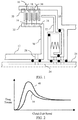
- FIG. 2 is a graph of clutch drag torque versus hub speed.
- FIG. 3 is a cross section of the transmission clutch of FIG. 1 with an oil deflector installed to reduce parasitic drag at low speeds.
- FIG. 4 is a graph of oil flow rate versus speed for the clutch with oil deflector of FIG. 3 .
- FIG. 1 is a cross section of a transmission clutch 10 .
- Clutch 10 selectively couples two rotating transmission elements to one another.
- a hub 12 is fixed to one of the rotating elements and a clutch housing 14 is fixed to the other rotating element.
- the clutch housing may be non-rotating.
- a plurality of friction plates 16 are splined to clutch hub 12 and interleaved with a plurality of separator plates 18 splined to clutch housing 14 .
- the leftmost separator plate which is called a reaction plate, is constrained axially by snap ring 20 .
- Piston 22 slides axially with respect to clutch housing 14 in response to fluid pressure to squeeze friction plates 16 between separator plates 18 .
- clutch hub 12 and clutch housing 14 rotate together as a single unit.
- the separator plates absorb the majority of this heat by increasing in temperature.
- a return spring pushes piston away from the separator plates and friction plates relieving the normal force.
- the clutch hub and clutch housing are free to rotate at different speeds from one another. Ideally, no torque would be transmitted in the released state. In practice, some parasitic drag remains.
- both clutch hub 12 and clutch housing 14 rotate about a central shaft 24 .
- Fluid is supplied for a variety of purposes through various axial channels 26 in central shaft 24 .
- One of these channels conveys pressurized fluid which is pressurized when the clutch is to be engaged.
- Another channel conveys fluid at low pressure for lubrication and heat removal.
- the fluid is routed to either the clutch hub 12 or the clutch housing via radial holes and seals.
- either clutch hub 12 or clutch housing 14 may be fixed to the central shaft thus eliminating the need to route fluid between components.
- the lubrication channel in the input shaft supplies fluid to a radial channel 28 in clutch hub 12 .
- Clutch hub 12 includes a disk 30 and an annular rim 32 .
- the friction plates 16 are splined to the annular rim 32 . Propelled by centrifugal forces, fluid exiting channel 28 tends to flow along the side of disk 30 and then spread out along the inner surface of annular rim 32 .
- a number of holes 34 in the annular rim permit the fluid to flow into the area between the friction plates and the separator plates. As the fluid flows past the separator plates, it absorbs heat, cooling the separator plates. Then, the fluid flows out of holes 36 in the clutch housing and drips back to the transmission sump.
- the rate of fluid flow into the clutch hub is determined by an intentional flow restriction, such as an orifice in channel 28 sized to limit flow to a desired flow level when the pressure is set to a given level in the valve body.
- the desired flow level is based on worst-case cooling and lubrication requirements.
- the worst-case requirements tend to occur at higher shaft speeds for two reasons. First, the energy absorbed by the separator plates during a shift is highest when the relative speed between clutch hub 12 and clutch housing 14 is highest. Although the ratio of the speeds of the hub and the housing varies among gear ratios, the speed difference tends to be highest when the absolute speeds are also the highest. Second, due to centrifugal forces on the fluid, the fluid is expelled from the clutch more quickly when the hub is rotating at high speed. Since the fluid spends less time in contact with the separator plates, a higher flow rate may be required to remove heat at a given rate.
- FIG. 2 illustrates the impact of clutch hub speed on clutch drag for a particular gear ratio (clutch housing speed is proportional to clutch hub speed for a particular gear ratio).
- Line 40 represents the drag torque for clutch 10 as a function of clutch hub speed.
- the drag is low because the relative velocity of the friction plates and separator plates is very low.
- the viscous drag forces increase nearly proportionally up to a point.
- the clutch hub speed further increases, the increased centrifugal forces cause the fluid to flow out of the clutch housing more rapidly such that the space between the friction plates and separator plates is partially evacuated.
- the drag torque reaches a peak and then declines as the effect of fluid evacuation becomes more important than the effect of greater relative speed.
- the drag torque levels off to a high-speed level.
- FIG. 3 illustrates a modified clutch hub design to reduce the parasitic drag, especially at low hub speeds.
- An oil deflector 42 is fixed to the clutch hub (at a different circumferential location than illustrated in FIG. 3 ).
- the oil deflector 42 is radially disposed between the outer annulus (annular rim) 32 and the inner annulus 33 .
- the oil deflector 42 circumscribes the orifice 28 to control (limit) the flow of fluid (oil) from the orifice 28 to the holes 34 .
- the deflector 42 forces the fluid bound for the holes 34 to travel between an oil-carry surface 52 of the disk 30 and end face 54 of the deflector 42 .
- the deflector 42 may define a reservoir 46 that collects the pooling fluid.
- the reservoir 46 may be defined by a radially extending dam 48 and a circumferential surface 58 that extends axially from the dam 48 to the end face 54 .
- the fluid that spills over dam 48 is directed away from the clutch by conical surface 50 of the oil deflector.
- Line 52 of FIG. 4 illustrates the resulting flow rate through the clutch pack. As a result, the parasitic drag is reduced as illustrated by line 54 of FIG. 2 .
Landscapes
- Engineering & Computer Science (AREA)
- General Engineering & Computer Science (AREA)
- Mechanical Engineering (AREA)
- Hydraulic Clutches, Magnetic Clutches, Fluid Clutches, And Fluid Joints (AREA)
- Mechanical Operated Clutches (AREA)
Abstract
Description
Claims (13)
Priority Applications (1)
| Application Number | Priority Date | Filing Date | Title |
|---|---|---|---|
| US16/038,466 US10830286B2 (en) | 2018-07-18 | 2018-07-18 | Transmission clutch with passive, speed-based fluid distribution |
Applications Claiming Priority (1)
| Application Number | Priority Date | Filing Date | Title |
|---|---|---|---|
| US16/038,466 US10830286B2 (en) | 2018-07-18 | 2018-07-18 | Transmission clutch with passive, speed-based fluid distribution |
Publications (2)
| Publication Number | Publication Date |
|---|---|
| US20200025264A1 US20200025264A1 (en) | 2020-01-23 |
| US10830286B2 true US10830286B2 (en) | 2020-11-10 |
Family
ID=69160991
Family Applications (1)
| Application Number | Title | Priority Date | Filing Date |
|---|---|---|---|
| US16/038,466 Expired - Fee Related US10830286B2 (en) | 2018-07-18 | 2018-07-18 | Transmission clutch with passive, speed-based fluid distribution |
Country Status (1)
| Country | Link |
|---|---|
| US (1) | US10830286B2 (en) |
Cited By (6)
| Publication number | Priority date | Publication date | Assignee | Title |
|---|---|---|---|---|
| US11428274B1 (en) | 2021-05-18 | 2022-08-30 | Ford Global Technologies, Llc | Vehicle clutch assembly having oil deflector |
| US11703091B2 (en) | 2021-09-03 | 2023-07-18 | Rolls-Royce Corporation | Cone clutch system |
| US11725699B2 (en) | 2021-12-29 | 2023-08-15 | Rolls-Royce Corporation | Cone clutch system including independent friction member |
| US11781603B2 (en) | 2021-09-07 | 2023-10-10 | Rolls-Royce Corporation | Cone clutch system |
| US12000437B1 (en) | 2023-06-27 | 2024-06-04 | Rolls-Royce Corporation | Cone clutch system including independent friction member |
| US12012997B2 (en) | 2021-09-07 | 2024-06-18 | Rolls-Royce Corporation | Cone clutch system |
Citations (15)
| Publication number | Priority date | Publication date | Assignee | Title |
|---|---|---|---|---|
| US4413716A (en) * | 1980-02-19 | 1983-11-08 | Laycock Engineering Limited | Friction clutches |
| US5090527A (en) | 1989-09-26 | 1992-02-25 | Jatco Corporation | Pressure control system for lock-up clutch in automotive automatic power transmission with compensation of fluid pressure in low engine speed range |
| DE4136040C1 (en) * | 1991-11-01 | 1993-01-07 | Mercedes-Benz Aktiengesellschaft, 7000 Stuttgart, De | Epicyclic gear drive with disc clutch or brake - has oil guide flange between planetary gear front ends and drive path, dividing two annular chambers |
| US5988335A (en) | 1998-06-02 | 1999-11-23 | Caterpillar Inc. | Control system for diverting oil from a clutch |
| US6244407B1 (en) | 1998-09-15 | 2001-06-12 | Borgwarner Inc. | Multi-disk friction device having forced lubrication on demand |
| WO2007142366A1 (en) * | 2006-06-09 | 2007-12-13 | Dynax Corporation | Cooling structure for wet dual clutch |
| US20080121488A1 (en) * | 2006-11-27 | 2008-05-29 | Tomoyuki Miyazaki | Starting clutch |
| US20100065395A1 (en) * | 2006-07-24 | 2010-03-18 | Magna Powertrain Ag & Co Kg | Multiplate wet clutch |
| US20130213740A1 (en) * | 2012-02-17 | 2013-08-22 | Honda Motor Co., Ltd | Lubricating structure of transmission |
| US8863923B2 (en) | 2007-01-22 | 2014-10-21 | Honda Motor Co., Ltd | Fluid transmission device |
| US9046139B2 (en) | 2012-12-21 | 2015-06-02 | Caterpillar Inc. | Clutch cooling system |
| US9091305B2 (en) | 2012-10-05 | 2015-07-28 | Magna Powertrain Ag | Clutch assembly with oil guide |
| US20170009817A1 (en) | 2015-07-07 | 2017-01-12 | Jtekt Corporation | Driving force transmission device |
| US20170261094A1 (en) * | 2016-03-09 | 2017-09-14 | Toyota Jidosha Kabushiki Kaisha | Lubricating system for engagement mechanism |
| US20180180113A1 (en) * | 2016-12-28 | 2018-06-28 | Honda Motor Co., Ltd. | Oil supply structure of clutch device |
-
2018
- 2018-07-18 US US16/038,466 patent/US10830286B2/en not_active Expired - Fee Related
Patent Citations (15)
| Publication number | Priority date | Publication date | Assignee | Title |
|---|---|---|---|---|
| US4413716A (en) * | 1980-02-19 | 1983-11-08 | Laycock Engineering Limited | Friction clutches |
| US5090527A (en) | 1989-09-26 | 1992-02-25 | Jatco Corporation | Pressure control system for lock-up clutch in automotive automatic power transmission with compensation of fluid pressure in low engine speed range |
| DE4136040C1 (en) * | 1991-11-01 | 1993-01-07 | Mercedes-Benz Aktiengesellschaft, 7000 Stuttgart, De | Epicyclic gear drive with disc clutch or brake - has oil guide flange between planetary gear front ends and drive path, dividing two annular chambers |
| US5988335A (en) | 1998-06-02 | 1999-11-23 | Caterpillar Inc. | Control system for diverting oil from a clutch |
| US6244407B1 (en) | 1998-09-15 | 2001-06-12 | Borgwarner Inc. | Multi-disk friction device having forced lubrication on demand |
| WO2007142366A1 (en) * | 2006-06-09 | 2007-12-13 | Dynax Corporation | Cooling structure for wet dual clutch |
| US20100065395A1 (en) * | 2006-07-24 | 2010-03-18 | Magna Powertrain Ag & Co Kg | Multiplate wet clutch |
| US20080121488A1 (en) * | 2006-11-27 | 2008-05-29 | Tomoyuki Miyazaki | Starting clutch |
| US8863923B2 (en) | 2007-01-22 | 2014-10-21 | Honda Motor Co., Ltd | Fluid transmission device |
| US20130213740A1 (en) * | 2012-02-17 | 2013-08-22 | Honda Motor Co., Ltd | Lubricating structure of transmission |
| US9091305B2 (en) | 2012-10-05 | 2015-07-28 | Magna Powertrain Ag | Clutch assembly with oil guide |
| US9046139B2 (en) | 2012-12-21 | 2015-06-02 | Caterpillar Inc. | Clutch cooling system |
| US20170009817A1 (en) | 2015-07-07 | 2017-01-12 | Jtekt Corporation | Driving force transmission device |
| US20170261094A1 (en) * | 2016-03-09 | 2017-09-14 | Toyota Jidosha Kabushiki Kaisha | Lubricating system for engagement mechanism |
| US20180180113A1 (en) * | 2016-12-28 | 2018-06-28 | Honda Motor Co., Ltd. | Oil supply structure of clutch device |
Cited By (6)
| Publication number | Priority date | Publication date | Assignee | Title |
|---|---|---|---|---|
| US11428274B1 (en) | 2021-05-18 | 2022-08-30 | Ford Global Technologies, Llc | Vehicle clutch assembly having oil deflector |
| US11703091B2 (en) | 2021-09-03 | 2023-07-18 | Rolls-Royce Corporation | Cone clutch system |
| US11781603B2 (en) | 2021-09-07 | 2023-10-10 | Rolls-Royce Corporation | Cone clutch system |
| US12012997B2 (en) | 2021-09-07 | 2024-06-18 | Rolls-Royce Corporation | Cone clutch system |
| US11725699B2 (en) | 2021-12-29 | 2023-08-15 | Rolls-Royce Corporation | Cone clutch system including independent friction member |
| US12000437B1 (en) | 2023-06-27 | 2024-06-04 | Rolls-Royce Corporation | Cone clutch system including independent friction member |
Also Published As
| Publication number | Publication date |
|---|---|
| US20200025264A1 (en) | 2020-01-23 |
Similar Documents
| Publication | Publication Date | Title |
|---|---|---|
| US10830286B2 (en) | Transmission clutch with passive, speed-based fluid distribution | |
| CN107202079B (en) | Hydraulic control system for wet double clutch | |
| US6244407B1 (en) | Multi-disk friction device having forced lubrication on demand | |
| US6189669B1 (en) | Multi-disk friction device having forced lubrication on demand | |
| US9453540B2 (en) | Double clutch system | |
| KR101384867B1 (en) | Multiple-disk brake in an automatic transmission having controllable cooling oil supply and method for operating the same | |
| US9841098B2 (en) | Transmission with fluid distributing clutch hub | |
| US6202814B1 (en) | Automatic transmission having grounded clutch with convergent cooling | |
| US6206163B1 (en) | Flow control capsule for clutch lubrication and cooling | |
| KR101265206B1 (en) | Hydraulic Clutch | |
| JP2004036887A (en) | Method and apparatus for supplying coolant for multiple disc clutch and multiple disc brake for automatic transmission | |
| US9915330B2 (en) | Four pass torque converter | |
| US20150226273A1 (en) | Wet Friction Clutch | |
| US9759302B2 (en) | Bypass clutch for a torque converter | |
| JP4715317B2 (en) | Transmission clutch structure | |
| EP0034404B1 (en) | Friction clutches | |
| WO2012147433A1 (en) | Friction member, clutch plate, clutch device, and torque converter | |
| KR101437152B1 (en) | Clutch | |
| US7481305B2 (en) | Lock-up mechanism for torque converter | |
| US8272985B2 (en) | Power transmission mechanism | |
| US7422536B2 (en) | Method and apparatus for cooling and lubricating a bearing device | |
| JP2768133B2 (en) | Fluid pressure clutch device | |
| KR101495819B1 (en) | Brake | |
| US9964183B2 (en) | Transmission with high speed clutch hub | |
| JP2026066152A (en) | Vehicle clutch mechanism |
Legal Events
| Date | Code | Title | Description |
|---|---|---|---|
| AS | Assignment |
Owner name: FORD GLOBAL TECHNOLOGIES, LLC, MICHIGAN Free format text: ASSIGNMENT OF ASSIGNORS INTEREST;ASSIGNORS:ZHANG, DENGFU;BECK, DAVID;REEL/FRAME:046382/0930 Effective date: 20180716 |
|
| FEPP | Fee payment procedure |
Free format text: ENTITY STATUS SET TO UNDISCOUNTED (ORIGINAL EVENT CODE: BIG.); ENTITY STATUS OF PATENT OWNER: LARGE ENTITY |
|
| STPP | Information on status: patent application and granting procedure in general |
Free format text: NON FINAL ACTION MAILED |
|
| STPP | Information on status: patent application and granting procedure in general |
Free format text: RESPONSE TO NON-FINAL OFFICE ACTION ENTERED AND FORWARDED TO EXAMINER |
|
| STPP | Information on status: patent application and granting procedure in general |
Free format text: NOTICE OF ALLOWANCE MAILED -- APPLICATION RECEIVED IN OFFICE OF PUBLICATIONS |
|
| STPP | Information on status: patent application and granting procedure in general |
Free format text: PUBLICATIONS -- ISSUE FEE PAYMENT VERIFIED |
|
| STCF | Information on status: patent grant |
Free format text: PATENTED CASE |
|
| LAPS | Lapse for failure to pay maintenance fees |
Free format text: PATENT EXPIRED FOR FAILURE TO PAY MAINTENANCE FEES (ORIGINAL EVENT CODE: EXP.); ENTITY STATUS OF PATENT OWNER: LARGE ENTITY |
|
| STCH | Information on status: patent discontinuation |
Free format text: PATENT EXPIRED DUE TO NONPAYMENT OF MAINTENANCE FEES UNDER 37 CFR 1.362 |
|
| FP | Lapsed due to failure to pay maintenance fee |
Effective date: 20241110 |