US10828023B2 - Method and apparatus for passing suture through tissue - Google Patents
Method and apparatus for passing suture through tissue Download PDFInfo
- Publication number
- US10828023B2 US10828023B2 US15/692,839 US201715692839A US10828023B2 US 10828023 B2 US10828023 B2 US 10828023B2 US 201715692839 A US201715692839 A US 201715692839A US 10828023 B2 US10828023 B2 US 10828023B2
- Authority
- US
- United States
- Prior art keywords
- suture
- arm
- hollow tube
- passer
- distal end
- Prior art date
- Legal status (The legal status is an assumption and is not a legal conclusion. Google has not performed a legal analysis and makes no representation as to the accuracy of the status listed.)
- Active, expires
Links
- 238000000034 method Methods 0.000 title description 61
- 241000287107 Passer Species 0.000 claims abstract description 278
- 239000000463 material Substances 0.000 claims description 16
- 230000000399 orthopedic effect Effects 0.000 claims description 7
- 238000005452 bending Methods 0.000 claims 1
- 210000001519 tissue Anatomy 0.000 description 200
- 238000010276 construction Methods 0.000 description 22
- 230000008901 benefit Effects 0.000 description 12
- 210000003811 finger Anatomy 0.000 description 12
- 238000001356 surgical procedure Methods 0.000 description 7
- 230000000694 effects Effects 0.000 description 6
- HLXZNVUGXRDIFK-UHFFFAOYSA-N nickel titanium Chemical compound [Ti].[Ti].[Ti].[Ti].[Ti].[Ti].[Ti].[Ti].[Ti].[Ti].[Ti].[Ni].[Ni].[Ni].[Ni].[Ni].[Ni].[Ni].[Ni].[Ni].[Ni].[Ni].[Ni].[Ni].[Ni] HLXZNVUGXRDIFK-UHFFFAOYSA-N 0.000 description 6
- 229910001000 nickel titanium Inorganic materials 0.000 description 6
- 150000001875 compounds Chemical class 0.000 description 3
- 239000012530 fluid Substances 0.000 description 3
- 210000001624 hip Anatomy 0.000 description 3
- 210000004394 hip joint Anatomy 0.000 description 3
- 230000003993 interaction Effects 0.000 description 3
- 230000008569 process Effects 0.000 description 3
- 229910001220 stainless steel Inorganic materials 0.000 description 3
- 239000010935 stainless steel Substances 0.000 description 3
- 0 CC1C(C2)C2C*1 Chemical compound CC1C(C2)C2C*1 0.000 description 2
- 230000009471 action Effects 0.000 description 2
- 210000000988 bone and bone Anatomy 0.000 description 2
- 239000002775 capsule Substances 0.000 description 2
- 238000002788 crimping Methods 0.000 description 2
- 238000000926 separation method Methods 0.000 description 2
- 239000000654 additive Substances 0.000 description 1
- 230000000996 additive effect Effects 0.000 description 1
- 238000013459 approach Methods 0.000 description 1
- 230000009286 beneficial effect Effects 0.000 description 1
- 230000007423 decrease Effects 0.000 description 1
- 230000003247 decreasing effect Effects 0.000 description 1
- 230000007812 deficiency Effects 0.000 description 1
- 210000003414 extremity Anatomy 0.000 description 1
- 238000004519 manufacturing process Methods 0.000 description 1
- 238000012986 modification Methods 0.000 description 1
- 230000004048 modification Effects 0.000 description 1
- 230000000926 neurological effect Effects 0.000 description 1
- 238000002355 open surgical procedure Methods 0.000 description 1
- 230000035515 penetration Effects 0.000 description 1
- 230000000717 retained effect Effects 0.000 description 1
- 210000003813 thumb Anatomy 0.000 description 1
- 230000002792 vascular Effects 0.000 description 1
Images


Classifications
-
- A—HUMAN NECESSITIES
- A61—MEDICAL OR VETERINARY SCIENCE; HYGIENE
- A61B—DIAGNOSIS; SURGERY; IDENTIFICATION
- A61B17/00—Surgical instruments, devices or methods, e.g. tourniquets
- A61B17/04—Surgical instruments, devices or methods, e.g. tourniquets for suturing wounds; Holders or packages for needles or suture materials
- A61B17/0469—Suturing instruments for use in minimally invasive surgery, e.g. endoscopic surgery
-
- A—HUMAN NECESSITIES
- A61—MEDICAL OR VETERINARY SCIENCE; HYGIENE
- A61B—DIAGNOSIS; SURGERY; IDENTIFICATION
- A61B17/00—Surgical instruments, devices or methods, e.g. tourniquets
- A61B17/04—Surgical instruments, devices or methods, e.g. tourniquets for suturing wounds; Holders or packages for needles or suture materials
- A61B17/0483—Hand-held instruments for holding sutures
-
- A—HUMAN NECESSITIES
- A61—MEDICAL OR VETERINARY SCIENCE; HYGIENE
- A61B—DIAGNOSIS; SURGERY; IDENTIFICATION
- A61B17/00—Surgical instruments, devices or methods, e.g. tourniquets
- A61B17/04—Surgical instruments, devices or methods, e.g. tourniquets for suturing wounds; Holders or packages for needles or suture materials
- A61B17/0485—Devices or means, e.g. loops, for capturing the suture thread and threading it through an opening of a suturing instrument or needle eyelet
-
- A—HUMAN NECESSITIES
- A61—MEDICAL OR VETERINARY SCIENCE; HYGIENE
- A61B—DIAGNOSIS; SURGERY; IDENTIFICATION
- A61B17/00—Surgical instruments, devices or methods, e.g. tourniquets
- A61B2017/00831—Material properties
- A61B2017/00862—Material properties elastic or resilient
-
- A—HUMAN NECESSITIES
- A61—MEDICAL OR VETERINARY SCIENCE; HYGIENE
- A61B—DIAGNOSIS; SURGERY; IDENTIFICATION
- A61B17/00—Surgical instruments, devices or methods, e.g. tourniquets
- A61B2017/00831—Material properties
- A61B2017/00867—Material properties shape memory effect
-
- A—HUMAN NECESSITIES
- A61—MEDICAL OR VETERINARY SCIENCE; HYGIENE
- A61B—DIAGNOSIS; SURGERY; IDENTIFICATION
- A61B17/00—Surgical instruments, devices or methods, e.g. tourniquets
- A61B17/04—Surgical instruments, devices or methods, e.g. tourniquets for suturing wounds; Holders or packages for needles or suture materials
- A61B17/06—Needles ; Sutures; Needle-suture combinations; Holders or packages for needles or suture materials
- A61B17/06004—Means for attaching suture to needle
- A61B2017/06009—Means for attaching suture to needle having additional means for releasably clamping the suture to the needle, e.g. actuating rod slideable within the needle
-
- A—HUMAN NECESSITIES
- A61—MEDICAL OR VETERINARY SCIENCE; HYGIENE
- A61B—DIAGNOSIS; SURGERY; IDENTIFICATION
- A61B17/00—Surgical instruments, devices or methods, e.g. tourniquets
- A61B17/04—Surgical instruments, devices or methods, e.g. tourniquets for suturing wounds; Holders or packages for needles or suture materials
- A61B17/06—Needles ; Sutures; Needle-suture combinations; Holders or packages for needles or suture materials
- A61B17/06004—Means for attaching suture to needle
- A61B2017/06014—Means for attaching suture to needle spring-loaded
-
- A—HUMAN NECESSITIES
- A61—MEDICAL OR VETERINARY SCIENCE; HYGIENE
- A61B—DIAGNOSIS; SURGERY; IDENTIFICATION
- A61B17/00—Surgical instruments, devices or methods, e.g. tourniquets
- A61B17/04—Surgical instruments, devices or methods, e.g. tourniquets for suturing wounds; Holders or packages for needles or suture materials
- A61B17/06—Needles ; Sutures; Needle-suture combinations; Holders or packages for needles or suture materials
- A61B17/06004—Means for attaching suture to needle
- A61B2017/06042—Means for attaching suture to needle located close to needle tip
-
- A—HUMAN NECESSITIES
- A61—MEDICAL OR VETERINARY SCIENCE; HYGIENE
- A61B—DIAGNOSIS; SURGERY; IDENTIFICATION
- A61B17/00—Surgical instruments, devices or methods, e.g. tourniquets
- A61B17/04—Surgical instruments, devices or methods, e.g. tourniquets for suturing wounds; Holders or packages for needles or suture materials
- A61B17/06—Needles ; Sutures; Needle-suture combinations; Holders or packages for needles or suture materials
- A61B17/06066—Needles, e.g. needle tip configurations
- A61B2017/061—Needles, e.g. needle tip configurations hollow or tubular
-
- A—HUMAN NECESSITIES
- A61—MEDICAL OR VETERINARY SCIENCE; HYGIENE
- A61B—DIAGNOSIS; SURGERY; IDENTIFICATION
- A61B17/00—Surgical instruments, devices or methods, e.g. tourniquets
- A61B17/30—Surgical pincettes without pivotal connections
- A61B2017/306—Surgical pincettes without pivotal connections holding by means of suction
Definitions
- This invention relates to surgical apparatus and procedures in general, and more particularly to surgical apparatus and procedures for passing suture through tissue.
- suture In many situations suture must be passed through tissue. In open surgical procedures, the suture is typically attached to a needle and the needle is then used to draw the suture through the tissue.
- closed surgical procedures e.g., so-called “keyhole” surgeries, where an interior surgical site is accessed through a narrow cannula
- Conventional needles are typically inadequate for these situations.
- suture passers are dedicated suture passing instruments generally comprising a shaft, a tissue-penetrating and suture-carrying working tip set at the distal end of the shaft, and a handle set at the proximal end of the shaft.
- suture passers all tend to suffer from one or more deficiencies, including but not limited to: (i) size; (ii) a need to place the suture adjacent to an edge of the tissue; (iii) difficulty in picking up suture on the far side of the tissue; (iv) complexity of operation; (v) cost of manufacture, etc.
- the present invention provides a new and improved method and apparatus for passing suture through tissue.
- a suture passer comprising:
- the hollow tube comprising a distal end, a proximal end, a lumen extending from the distal end to the proximal end, and a window formed in the sidewall of the hollow tube, the window communicating with the lumen;
- a clamping rod slidably received in the lumen of the hollow tube, the clamping rod comprising a distal end and a proximal end, the distal end being bifurcated into a first arm and a second arm, one of the first and second arms extending distally of the other of the first and second arms and including a clamping surface, and at least one of the first and second arms being outwardly biased such that when the clamping rod is moved distally so that the distal end of the at least one outwardly biased arm is adjacent to the window, the distal end of the at least one outwardly biased arm extends outwardly through the window.
- a method for passing suture through an object comprising:
- a suture passer comprising:
- a suture passer comprising:
- the hollow tube comprising a pointed distal end, a proximal end and a lumen extending from the distal end to the proximal end;
- a clamping rod slidably received in the lumen of the hollow tube, the clamping rod comprising a distal end and a proximal end, the distal end being bifurcated into a first arm and a second arm, the first arm extending distally of the second arm and including a clamping surface, and the second arm being outwardly biased such that when the clamping rod is moved distally so that the distal end of the second arm extends out of the distal end of the hollow tube, the distal end of the second arm extends laterally of the hollow tube.
- a method for passing suture through an object comprising:
- a suture passer comprising:
- a suture passer comprising:
- a shaft comprising a distal end, a proximal end, a lumen extending from the proximal end toward the distal end, and a window formed in the sidewall of the shaft, the window communicating with the lumen;
- suture spear movable within the lumen of the shaft, the suture spear comprising a distal end and a proximal end, the distal end being pointed to pierce a suture located in the window.
- a method for passing suture through an object comprising:
- a suture passer comprising:
- a suture passer comprising:
- the hollow tube comprising a distal end, a proximal end, a lumen extending from the distal end to the proximal end, and a window formed in the sidewall of the hollow tube, the window communicating with the lumen;
- a clamping rod slidably received in the lumen of the hollow tube, the clamping rod comprising a distal end and a proximal end, the distal end including a clamping surface, and the distal end being outwardly biased such that when the clamping rod is moved distally so that the distal end of the clamping rod is adjacent to the window, the distal end of the clamping rod extends outwardly through the window.
- a method for passing suture through an object comprising:
- a suture passer comprising:
- a suture passer comprising:
- the hollow tube comprising a distal end, a proximal end, and a lumen extending from the distal end to the proximal end;
- clamping rod slidably received in the lumen of the hollow tube, the clamping rod comprising a distal end and a proximal end, the distal end being bifurcated into a first arm and a second arm, one of the first and second arms extending distally of the other of the first and second arms and including a clamping surface;
- At least one of the first arm and the second arm comprises a friction-enhancing surface for facilitating manipulation of a suture via engagement of the suture with the friction-enhancing surface.
- a method for passing suture through an object comprising:
- a suture passer comprising:
- a suture passer comprising:
- the hollow tube comprising a pointed distal end, a proximal end and a lumen extending from the distal end to the proximal end;
- a clamping rod slidably received in the lumen of the hollow tube, the clamping rod comprising a distal end and a proximal end, the distal end being bifurcated into a first arm and a second arm, the first arm extending distally of the second arm and including a clamping surface, and the second arm being outwardly biased such that when the clamping rod is moved distally, the distal end of the second arm extends laterally of the hollow tube, and wherein the second arm is configured to releasably hold a suture to the distal end of the second arm.
- a method for passing suture through an object comprising:
- a suture passer comprising:
- a suture passer comprising:
- hollow tube said hollow tube comprising a distal end, a proximal end, and a lumen extending from said distal end to said proximal end;
- suture manipulation rod slidably received in said lumen of said hollow tube and selectively projectable out said distal end of said hollow tube, said suture manipulation rod comprising a distal end and a proximal end, said distal end of said suture manipulation rod being bifurcated into a first arm and a second arm, wherein said first arm includes a hook comprising a proximally oriented hooking surface and a return extending proximally of said hooking surface;
- said hollow tube and said suture manipulation rod are sized so that said suture manipulation rod may capture a suture disposed adjacent to said distal end of said hollow tube and draw the suture into said lumen of said hollow tube, and further wherein, after a suture has been drawn into said lumen of said hollow tube, distal movement of said suture manipulation rod causes the suture to be expelled from said hollow tube.
- a method for passing suture through an object comprising:
- a suture passer comprising:
- a suture passer comprising:
- hollow tube said hollow tube comprising a distal end, a proximal end, and a lumen extending from said distal end to said proximal end;
- suture manipulation rod slidably received in said lumen of said hollow tube and selectively projectable out said distal end of said hollow tube, said suture manipulation rod comprising a distal end and a proximal end, said distal end of said suture manipulation rod comprising a hook comprising a proximally oriented hooking surface and a return extending proximally of said hooking surface, and a pushing surface disposed proximally of said return of said hook of said suture manipulation rod;
- said hollow tube and said suture manipulation rod are sized so that said suture manipulation rod may capture a suture disposed adjacent to said distal end of said hollow tube and draw the suture into said lumen of said hollow tube, and further wherein, after a suture has been drawn into said lumen of said hollow tube, distal movement of said suture manipulation rod causes the suture to be expelled from said hollow tube.
- a method for passing suture through an object comprising:
- a suture passer comprising:
- FIGS. 1-11 are schematic views showing a novel suture passer formed in accordance with the present invention.
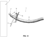
- FIGS. 12-25 are schematic views showing an exemplary manner of passing suture through tissue using the novel suture passer of FIGS. 1-11 ;
- FIGS. 26-29 are schematic views showing various configurations for the clamping surface of the first arm of the clamping rod of the suture passer of FIGS. 1-11 ;
- FIGS. 29A and 29B are schematic views showing a modified form of the novel suture passer of FIGS. 1-11 , wherein an arm of the suture passer includes a plurality of suture-engaging projections on its distal side;
- FIGS. 29C and 29D are schematic views showing a modified form of the novel suture passer of FIGS. 1-11 , wherein an arm of the suture passer includes a plurality of suture-engaging projections on its proximal side;
- FIGS. 30 and 31 are schematic views showing another configuration for the suture passer of the present invention, wherein the clamping rod and hollow tube are configured so as to allow suture to slide between the clamping rod and the hollow tube;
- FIGS. 32 and 33 are schematic views showing another configuration for the suture passer of the present invention, wherein the clamping rod is configured to pierce the suture when the clamping rod is moved proximally;
- FIGS. 34 and 35 are schematic views illustrating how the lengths of the first and second arms of the bifurcated distal end of the clamping rod can vary from the construction shown in FIGS. 1-11 ;
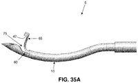
- FIGS. 35A-35C are schematic views showing another novel form of suture passer formed in accordance with the present invention.
- FIGS. 35D-35F are schematic views showing the novel suture passer of FIGS. 35A-35C securing a suture to the distal end of the suture passer;
- FIGS. 35G-35I are schematic views showing another novel form of suture passer formed in accordance with the present invention.
- FIGS. 35J-35L are schematic views showing the novel suture passer of FIGS. 35G-35I securing a suture to the distal end of the suture passer;
- FIGS. 35M-35O are schematic views showing another novel form of suture passer formed in accordance with the present invention.
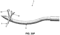
- FIGS. 35P-35R are schematic views showing the novel suture passer of FIGS. 35M-35O securing a suture to the distal end of the suture passer;
- FIGS. 36-40 are schematic views showing another novel form of suture passer formed in accordance with the present invention.
- FIGS. 40A and 40B are schematic views showing a modified form of the novel suture passer of FIGS. 36-40 , wherein an arm of the suture passer includes a plurality of suture-engaging projections on its distal side;
- FIGS. 41-47 are schematic views showing still another novel form of suture passer formed in accordance with the present invention.
- FIGS. 48-60 are schematic views showing yet another novel form of suture passer formed in accordance with the present invention.
- FIGS. 61-64 are schematic views showing an exemplary manner of passing suture using the novel suture passer of FIGS. 48-60 ;
- FIGS. 65-67 show variations of the novel suture passer shown in FIGS. 48-60 ;
- FIGS. 68-81 are schematic views showing another novel form of suture passer formed in accordance with the present invention.
- FIGS. 82-84 are schematic views showing another novel form of suture passer formed in accordance with the present invention.
- FIGS. 85 and 86 are schematic views showing still another novel form of suture passer formed in accordance with the present invention.
- FIGS. 87-91 are schematic views showing yet another novel form of suture passer formed in accordance with the present invention.
- FIGS. 92-95 are schematic views showing another suture passer formed in accordance with the present invention, wherein the suture passer has its hooking rod disposed within the interior of its hollow tube;
- FIGS. 96-98 are schematic views showing the suture passer of FIGS. 92-95 with the distal end of its hooking rod projecting out the distal end of its hollow tube, wherein the first arm of the hooking rod is shown as extending at an angle to the local longitudinal axis of the distal end of the hollow tube when the first arm projects out of the distal end of the hollow tube;
- FIG. 99 is a schematic view showing the suture passer of FIGS. 92-95 and 96-98 , except that the first arm of the hooking rod is configured to extend parallel to the local longitudinal axis of the distal end of the hollow tube when the first arm projects out of the distal end of the hollow tube;
- FIGS. 100-109 are schematic views showing the suture passer of FIGS. 92-99 capturing a suture by means of the interaction of the first arm and the second arm of the hooking rod, and drawing a portion of that suture within the interior of the hollow tube by means of the hooking surface of the first arm 275 A of hooking rod 215 A;
- FIGS. 110-112 are schematic views showing the suture passer of FIGS. 92-109 releasing a suture which had been previously captured by the suture passer and which had a portion of that suture “stored” within the interior of hollow tube 210 A, e.g., by using the distal end of the second arm of the hooking rod to push the “stored” suture back out of the hollow tube;
- FIG. 113 is a schematic view showing an alternative form of hooking rod which may be used in accordance with the present invention shown in FIGS. 92-112 ;
- FIGS. 114 and 115 are schematic views showing another form of suture passer formed in accordance with the present invention.
- the present invention provides a new and improved method and apparatus for passing suture through tissue.
- Suture passer 5 formed in accordance with the present invention.
- Suture passer 5 generally comprises a hollow tube 10 and a clamping rod 15 slidably disposed within the lumen of hollow tube 10 , as will hereinafter be discussed in further detail.
- hollow tube 10 comprises a distal end 20 preferably terminating in a sharp point 22 , and a proximal end 25 preferably terminating in a handle 23 , with a lumen 30 extending therebetween.
- the pointed hollow tube 10 essentially comprises a hollow needle adapted to pierce tissue.
- Hollow tube 10 further comprises a window 35 which extends radially into the hollow tube and communicates with lumen 30 .
- Window 35 is sized so as to selectively receive a suture S therein, as will hereinafter be discussed in further detail.
- Window 35 preferably comprises an inclined distal surface 40 and an inclined proximal surface 45 .
- distal surface 40 and proximal surface 45 are inclined in the same direction, and preferably both surfaces are inclined distally (e.g., in the manner shown in FIGS. 1-11 ).
- the forward incline of inclined distal surface 40 allows suture to more easily pass into and out of window 35 .
- the forward incline of inclined proximal surface 45 provides an undercut which helps to trap the suture S between the clamping surface 47 of clamping rod 15 and the inclined proximal surface 45 of window 35 , as will hereinafter be discussed in further detail.
- Hollow tube 10 is preferably formed out of a substantially rigid material (e.g., stainless steel) so as to maintain rigidity when passing through tissue, particularly relatively tough fibrous tissue (e.g., the labrum of the hip).
- a substantially rigid material e.g., stainless steel
- hollow tube 10 is curved, however, it should be appreciated that hollow tube 10 can be formed in other configurations well known in the art (e.g., straight, etc.).
- Clamping rod 15 comprises a distal end 50 ( FIG. 9 ) and a proximal end 55 ( FIG. 9 ). Distal end 50 of clamping rod 15 is bifurcated so as to form a first arm 60 and a second arm 65 .
- First arm 60 comprises the aforementioned clamping surface 47 , with clamping surface 47 extending radially from the longitudinal axis of clamping rod 15 .
- Clamping surface 47 may take the form of a hook, as shown in FIGS. 1-11 . This hook helps trap the suture S between clamping surface 47 of clamping rod 15 and inclined proximal surface 45 of window 35 , in the manner shown in FIGS. 10 and 11 .
- Second arm 65 extends parallel to first arm 60 when clamping rod 15 is disposed within lumen 30 of hollow tube 10 , with second arm 65 terminating proximally of first arm 60 , shy of clamping surface 47 .
- Second arm 65 is outwardly biased so that when second arm 65 advances past window 35 , second arm 65 passes radially outwardly through window 35 so as to project at an angle of approximately 10-120 degrees relative to the adjacent longitudinal axis of first arm 60 ( FIG. 6 ) (i.e., the longitudinal axis of first arm 60 at the point adjacent to where second arm 65 advances outwardly through window 35 ), and more preferably at an angle of approximately 30-90 degrees to the instantaneous longitudinal axis of first arm 60 , whereby to create a funnel region 75 ( FIG. 7 ) between hollow tube 10 and second arm 65 when second arm 65 extends out window 35 .
- second arm 65 is preferably formed out of a material consistent with this spring bias (e.g., a superelastic material such as Nitinol, etc.).
- a superelastic material such as Nitinol, etc.
- the entire clamping rod 15 is formed out of a superelastic material such as Nitinol.
- clamping rod 15 extends through lumen 30 of hollow tube 10 and is connected to an actuator 72 ( FIG. 1 ) which is movably mounted to handle 23 , such that movement of actuator 72 relative to handle 23 will cause movement of clamping rod 15 relative to hollow tube 10 .
- a piece of suture S may be clamped to the distal end of suture passer 5 by (i) moving clamping rod 15 to the position shown in FIGS. 5 and 6 (e.g., by moving actuator 72 distally relative to handle 23 ) so that clamping surface 47 of first arm 60 is distal to window 35 , and so that second arm 65 extends out of window 35 ; (ii) positioning the suture S in window 35 ( FIGS.
- a clamped piece of suture may thereafter be released from suture passer 5 by (a) moving clamping rod 15 distally ( FIGS. 8 and 9 ) so as to space clamping surface 47 of first arm 60 away from proximal surface 45 of window 35 ; and (b) causing suture S to be withdrawn from window 35 ( FIG. 7 ), either by moving suture S relative to suture passer 5 or by moving suture passer 5 relative to suture S or by moving both suture S and suture passer 5 relative to one another.
- both first arm 60 and second arm 65 are disposed within lumen 30 of hollow tube 10 , so that the distal end of suture passer 5 presents a smooth outer surface, whereby to facilitate passage of the distal end of suture passer 5 through tissue.
- the novel suture passer 5 can be used to pass suture S from the near side of tissue T to the far side of tissue T (i.e., in an “antegrade” manner).
- the preliminary loading of suture S into suture passer 5 may be performed away from the surgical site (e.g., outside of the patient) or it may be performed adjacent to the near side of the tissue T which is to be sutured (e.g., inside of the patient).
- clamping rod 15 is advanced to its most distal position so that second arm 65 advances out of window 35 , whereby to project out of the axis of hollow tube 10 and create the aforementioned funnel region 75 .
- Suture S is then guided into window 35 using this funnel effect, as seen in FIG. 13 , either by moving suture S relative to suture passer 5 or by moving suture passer 5 relative to suture S or by moving both suture S and suture passer 5 relative to one another.
- Clamping rod 15 is then retracted proximally so that clamping surface 47 clamps suture S between clamping surface 47 of first arm 60 and proximal surface 45 of window 35 . See FIG. 14 .
- Suture passer 5 is then advanced distally so that window 35 passes through tissue T, whereby to carry suture S through the tissue ( FIG. 15 ).
- clamping rod 15 is advanced distally so that clamping surface 47 is disposed distal to window 35 , thereby releasing suture S from suture passer 5 .
- Suture passer 5 and/or suture S are then manipulated so that suture S is clear of window 35 ( FIG. 17 ).
- Clamping rod 15 is then moved proximally so as to retract first arm 60 and second arm 65 back into hollow tube 10 .
- Suture passer 5 may then be withdrawn back through tissue T, leaving suture S extending through tissue T, as shown in FIG. 18 .
- the novel suture passer 5 can be used to draw suture S from the far side of tissue T to the near side of tissue T (i.e., in a “retrograde” manner).
- the suture S is loaded into suture passer 5 on the far side of the tissue T. This is done by first passing suture passer 5 through tissue T so that window 35 resides on the far side of the tissue, and then moving clamping rod 15 distally so that second arm 65 extends out of window 35 , substantially perpendicularly to hollow tube 10 , whereby to create the aforementioned funnel region 75 ( FIGS. 19 and 20 ). This funnel effect is then used to guide free suture (disposed on the far side of tissue T) into window 35 (see FIG. 21 ), either by moving suture S relative to suture passer 5 or by moving suture passer 5 relative to suture S or by moving both suture S and suture passer 5 relative to one another. If desired, the suture S may be tensioned so as to help draw it into the window 35 .
- clamping rod 15 is retracted proximally so as to releasably secure suture S between clamping surface 47 and proximal surface 45 of window 35 ( FIG. 22 ).
- Hollow tube 10 is then retracted proximally through tissue T, carrying suture S therethrough ( FIG. 23 ). If desired, suture S can then be released from suture passer 5 by moving clamping rod 15 distally ( FIGS. 24 and 25 ).
- a mattress stitch may be placed in the tissue ( FIG. 25 ).
- the novel suture passer 5 may also be used to pass suture S around a side edge of the tissue T, rather than passing the suture S through the tissue.
- the suture passer could then be used to retrieve the suture on the far side of the tissue and draw it back around the side edge of the tissue so that the suture is brought to the near side of the tissue.
- the novel suture passer 5 has the ability to both pass (advance) and retrieve (draw) the suture S through and/or around the tissue in a continuous series of steps. This allows the surgeon to complete the desired suture passing without having to remove the suture passer 5 from the portal through which the suture passer 5 is being used. Significantly, this passing/retrieving process can be accomplished with a single instrument, rather than requiring one instrument for passing and a separate instrument for retrieving. This offers significant advantages in convenience and in reducing surgery time.
- clamping surface 47 of clamping rod 15 may take the form of a hook, as shown in FIGS. 1-11 .
- This hook may have various degrees of depth and return, as seen in FIGS. 26-28 .
- clamping surface 47 may be substantially flat, as shown in FIG. 29 .
- second arm 65 of suture passer 5 may include a plurality of suture-engaging projections 76 on its distal side.
- Suture-engaging projections 76 allow the user to more aggressively engage (e.g., in a contact or frictional sense) suture S with second arm 65 , whereby to facilitate manipulation of suture S via engagement with second arm 65 .
- the user can “grip” the suture S with the suture-engaging projections 76 of second arm 65 and “drag” the suture S into a desired position.
- the suture-engaging projections 76 of second arm 65 can assist in dragging suture S into window 35 . More particularly, as the clamping rod 15 is moved proximally in hollow tube 10 , the second arm 65 retracts into the lumen of the hollow tube 10 . As it does so, if the suture S is in contact with the suture-engaging projections 76 of second arm 65 , suture S will be drawn into window 35 . Once in window 35 , the suture S is then clamped between clamping surface 47 of clamping rod 15 and inclined proximal surface 45 of window 35 as described above.
- second arm 65 of suture passer 5 may include a plurality of suture-engaging projections 76 on its proximal side.
- suture-engaging projections 76 allow the user to more aggressively engage (e.g., in a contact or frictional sense) suture S with second arm 65 , whereby to facilitate manipulation of suture S via engagement with second arm 65 .
- suture-engaging projections 76 may also be provided on both the distal and proximal sides of second arm 65 , and/or on one or both of the lateral sides of second arm 65 .
- suture-engaging projections 76 essentially constitute a
- friction-enhancing surface on second arm 65 so as to allow second arm 65 to engage and “drag” suture S about a surgical site.
- the friction-enhancing surface(s) on second arm 65 may be formed with a variety of geometries, e.g., barbs, fingers, ribs, threads or other surface texturing which increases the frictional aspects of second arm 65 at a desired location or locations.
- the suture passer may be constructed so that the suture S is slidably captured—but not clamped—between clamping surface 47 of clamping rod 15 and inclined proximal surface 45 of window 35 .
- suture S is slidably captured between the two surfaces (i.e., clamping surface 47 and proximal surface 45 ), in the manner shown in FIGS. 30 and 31 .
- clamping rod 15 may be limited in its proximal travel (e.g., by means of interaction between actuator 72 and handle 23 ) in order to provide a gap sufficient to slidingly capture, but not bind, suture S. This gap may be equal to, or larger than, the diameter of suture S.
- first arm 60 of clamping rod 15 may include a pointed return 77 , with pointed return 77 being configured and located such that it will spear suture S when clamping rod 15 is moved proximally.
- first and second arms 60 , 65 of clamping rod 15 can vary from the construction shown in FIGS. 1-11 .
- the distance between the distal tip of second arm 65 and clamping surface 47 is approximately the length of window 35 , as shown in FIG. 34 .
- only a nominal gap is provided between the distal tip of second arm 65 and clamping surface 47 ( FIG. 35 ). This construction can provide for improved capturing of suture S to suture passer 5 .
- suction may be applied to lumen 30 of hollow tube 10 proximal to window 35 . This suction will draw fluid into window 35 , and the fluid entering window 35 will assist suture S in seating itself into window 35 as the suture S approaches window 35 .
- fluid is delivered down lumen 30 of hollow tube 10 so as to assist ejection of suture S from window 35 once the clamping rod 15 has released suture S.
- hollow tube 10 comprises a second window 35 opposite first window 35 , and the distal end of clamping rod 15 is trifurcated so as to form a first arm 60 carrying a pair of clamping surfaces 47 and a pair of second arms 65 , with each of the second arms 65 being outboard of first arm 60 and being biased out a window 35 .
- suture can be clamped on either side of hollow tube 10 .
- the suture passer may further comprise a push rod to assist in ejecting suture S from window 35 .
- the push rod may be a component separate from clamping rod 15 (but slidably movable relative thereto), or it may be integrated with clamping rod 15 (e.g., slidably movable thereon).
- FIGS. 35A-35C it is also possible to form novel suture passer 5 so that (i) first arm 60 is shorter than second arm 65 , and (ii) clamping surface 47 is formed on the outwardly biased second arm 65 (rather than on first arm 60 ).
- funnel region 75 is formed between the distal end of shaft 10 and first arm 60 .
- FIGS. 35D-35F show the novel suture passer of FIGS. 35A-35C securing a suture S to the distal end of the suture passer.
- first arm 60 may be omitted entirely, in which case the distal end of clamping rod 15 preferably comprises only outwardly biased second arm 65 .
- novel suture passer 5 may be constructed so that first arm 60 (carrying clamping surface 47 ) is outwardly biased, so that first arm 60 (and clamping surface 47 ) extends out window 35 when clamping rod 15 is moved distally.
- the funnel region 75 is formed between the distal end of shaft 10 and first arm 60 .
- FIGS. 35J-35L show the novel suture passer of FIGS. 35G-35I securing a suture S to the distal end of the suture passer.
- first arm 60 is outwardly biased and carries clamping surface 47 (e.g., in the manner shown in FIGS. 35G-35I and FIGS. 35J-35L )
- second arm 65 may be omitted entirely, in which case the distal end of clamping rod 15 preferably comprises only outwardly biased first arm 60 (with clamping surface 47 ).
- novel suture passer 5 may be constructed so that both first arm 60 (carrying clamping surface 47 ) and second arm 65 are outwardly biased, so that both first arm 60 (and clamping surface 47 ) and second arm 65 extend out window 35 when clamping rod 15 is moved distally.
- funnel region 75 is formed between first arm 60 and second arm 65 .
- FIGS. 35P-35R show the novel suture passer of FIGS. 35M-35O securing a suture S to the distal end of the suture passer.
- window 35 may be eliminated, and clamping rod 15 may clamp suture S against the distal end surface 80 of hollow tube 10 .
- second arm 65 of suture passer 5 may include a plurality of suture-engaging projections 76 on its distal side.
- suture-engaging projections 76 allow the user to more aggressively engage (e.g., in a contact or frictional sense) suture S with second arm 65 , whereby to facilitate manipulation of suture S via engagement with second arm 65 .
- the user can “grip” the suture S with the suture-engaging projections 76 of second arm 65 and “drag” the suture S into a desired position.
- the suture-engaging projections 76 of second arm 65 can assist in dragging suture S against the distal end of hollow tube 10 . More particularly, as the clamping rod 15 is moved proximally in hollow tube 10 , the second arm 65 retracts into the lumen of hollow tube 10 . As it does so, if the suture S is in contact with the suture-engaging projections 76 of second arm 65 , suture S will be drawn into engagement with the distal end of hollow tube 10 and then clamped in place by first arm 60 .
- second arm 65 of suture passer 5 may include a plurality of suture-engaging projections 76 on its proximal side (e.g., in a manner analogous to that shown in FIGS. 29C and 29D ).
- suture-engaging projections 76 allow the user to more aggressively engage (e.g., in a contact or frictional sense) suture S with second arm 65 , whereby to facilitate manipulation of suture S via engagement with second arm 65 .
- suture-engaging projections 76 may also be provided on both the distal and proximal sides of second arm 65 , and/or on one or both lateral sides of second arm 65 .
- suture-engaging projections 76 essentially constitute a
- suture engaging surface on second arm 65 so as to allow second arm 65 to engage and “drag” suture S about a surgical site.
- the suture engaging surface(s) on second arm 65 may be formed with a variety of geometries, e.g., barbs, fingers or other surface texturing which increases the frictional aspects of second arm 65 at a desired location or locations.
- the distal end surface 80 of hollow tube 10 can be disposed substantially perpendicular to the longitudinal axis of hollow tube 10 , whereby to enhance clamping of suture S against distal end surface 80 of hollow tube 10 .
- suture passer 5 preferably comprises a handle 23
- handle 23 preferably comprises an actuator 72 which actuates clamping rod 15 so as to clamp and/or release suture S.
- actuator 72 may comprise a lock or detent which maintains the position of clamping rod 15 relative to hollow tube 10 .
- the lock or detent may hold the clamping rod in a distal position and/or in a proximal position (e.g., while it is clamping suture S).
- Actuator 72 may also comprise a spring to bias clamping rod 15 proximally or distally. In one preferred form of the invention, this spring biases the clamping rod in a proximal direction (for example, to clamp suture S between clamping surface 47 and inclined proximal surface 45 ).
- FIGS. 48-60 there is shown a novel suture passer 105 also formed in accordance with the present invention.
- Suture passer 105 will sometimes hereinafter be referred to as the “spear” suture passer.
- the spear suture passer 105 generally comprises an outer shaft tube 110 , an inner guide tube 112 fixedly disposed within the interior of outer shaft tube 110 , and a suture spear 116 slidably disposed within the lumen of inner guide tube 112 , as will hereinafter be discussed in further detail.
- outer shaft tube 110 comprises a distal end 120 preferably terminating in a sharp point 122 , and a proximal end 125 preferably terminating in a handle 123 , with a lumen 130 extending therebetween.
- the pointed outer shaft tube 110 essentially comprises a hollow needle adapted to pierce tissue.
- Outer shaft tube 110 further comprises a window 135 which extends radially into the outer shaft tube and communicates with lumen 130 .
- Window 135 is sized so as to selectively receive a suture S therein, as will hereinafter be discussed in further detail.
- Window 135 comprises a pair of distal surfaces 140 , a pair of proximal surfaces 145 , and a pair of side surfaces 146 .
- distal surfaces 140 and proximal surfaces 145 extend substantially perpendicular to the longitudinal axis of outer shaft tube 110 ( FIG. 49 ), and side surfaces 146 preferably extend substantially parallel to the longitudinal axis of outer shaft tube 110 ( FIG. 50 ).
- Distal surfaces 140 are preferably spaced from proximal surfaces 145 by a distance which is somewhat larger than the diameter of suture S, so that window 135 provides an adequate seat for suture S, as will hereinafter be discussed in further detail.
- Outer shaft tube 110 is preferably formed out of a substantially rigid material (e.g., stainless steel) so as to maintain rigidity when passing through tissue, particularly relatively tough fibrous tissue (e.g., the labrum of the hip).
- a substantially rigid material e.g., stainless steel
- the distal end 120 of outer shaft tube 110 is curved (see, for example, FIGS. 49, 58 and 59 ), however, it should also be appreciated that outer shaft tube 110 can be formed in other configurations well known in the art (e.g., straight, etc.).
- Inner guide tube 112 comprises a distal end 150 ( FIG. 52 ) and a proximal end 155 ( FIG. 60 ), with a lumen 156 extending therebetween.
- Inner guide tube 112 is fixedly disposed within outer shaft tube 110 so that the distal end 150 of inner guide tube 112 terminates proximal to window 135 in outer shaft tube 110 , with lumen 156 of inner guide tube 112 being substantially aligned with the center of window 135 .
- the distal end 150 of inner guide tube 112 preferably terminates just proximal to window 135 of outer shaft tube 110 . See, for example, FIGS. 50, 52 and 53 .
- inner guide tube 112 acts as a guide and stiffening member for suture spear 116 , which is selectively extendable out of the inner guide tube (and hence selectively extendable across window 135 ) and selectively withdrawable back into the inner guide tube (and hence selectively withdrawable out of window 135 ).
- Suture spear 116 comprises a distal end 158 ( FIG. 52 ) and a proximal end 159 ( FIG. 60 ). Distal end 158 of suture spear 116 terminates in a point 161 . It will be appreciated that suture spear 116 essentially comprises a needle which, as will hereinafter be discussed, is adapted to pierce suture. Suture spear 116 is slidably disposed within lumen 156 of inner guide tube 112 , such that suture spear 116 can extend across window 135 ( FIG. 52 ) or be withdrawn from window 135 ( FIG. 53 ).
- the proximal end 159 of suture spear 116 extends out of the proximal end 155 of inner guide tube 112 and is connected to an actuator 172 (e.g., a thumb slide) which is movably mounted to handle 123 , such that movement of actuator 172 relative to handle 123 will cause movement of suture spear 116 relative to inner guide tube 112 (and hence relative to outer shaft tube 110 ). Specifically, movement of actuator 172 relative to handle 123 will cause the distal end of suture spear 116 to intrude across, or be withdrawn from, window 135 of outer shaft tube 110 .
- an actuator 172 e.g., a thumb slide
- inner guide tube 112 is positioned within outer shaft tube 110 so that the inner guide tube (and hence the suture spear 116 ) is aligned with a suture S that is laid in window 135 so as to ensure that suture spear 116 can securely pierce the suture S, as will hereinafter be discussed.
- a piece of suture S may be clamped to the distal end of suture passer 105 by (i) moving suture spear 116 proximally so that the distal end 158 of suture spear 116 is withdrawn from window 135 of outer shaft tube 110 , in the manner shown in FIG. 54 (e.g., by moving actuator 172 proximally relative to handle 123 ); (ii) positioning the suture S in window 135 ( FIG. 54
- suture spear 116 distally (e.g., by moving actuator 172 distally relative to handle 123 ) so as to cause suture spear 116 to “spear” (e.g., penetrate) suture S, as shown in FIG. 56 , whereby to secure suture S to suture passer 105 .
- pear e.g., penetrate
- a speared piece of suture S may thereafter be released from suture passer 105 by (a) moving suture spear 116 proximally ( FIG. 57 ) so as to “unspear” suture S; and (b) causing suture S to be withdrawn from window 135 .
- the novel suture passer 105 can be used to pass suture S from the near side of tissue T to the far side of tissue T (i.e., in an “antegrade” manner).
- the preliminary loading of suture S into suture passer 105 may be performed away from the surgical site (e.g., outside of the patient) or it may be performed adjacent to the near side of the tissue T which is to be sutured (e.g., inside of the patient).
- suture S may be loaded into suture passer 105 by retracting suture spear 116 out of window 135 of outer shaft tube 110 ( FIG. 54 ), guiding suture S into window 135 ( FIG. 55 ), and then advancing suture spear 116 distally through suture S ( FIG. 56 ), whereby to secure suture S to suture passer 105 . See FIG. 61 .
- Suture passer 105 is then advanced distally so that window 135 passes through tissue T, whereby to carry suture S through the tissue ( FIG. 62 ). With suture S extending through tissue T, and looking now at FIG. 63 , suture spear 116 is retracted proximally so as to release suture S from suture passer 105 , and then suture passer 105 and/or suture S are manipulated so that suture S is clear of window 135 ( FIG. 63 ). Suture passer 105 may then be withdrawn back through tissue T, leaving suture S extending through tissue T, as shown in FIG. 64 .
- the spear suture passer 105 can be used to draw suture S from the far side of tissue T to the near side of tissue T (i.e., in a “retrograde” manner).
- the suture S is loaded into suture passer 5 on the far side of the tissue T. This is done by first passing suture passer 105 through tissue T so that window 135 resides on the far side of the tissue, and then moving suture spear 116 proximally so that suture spear 116 is withdrawn from window 135 (if the suture spear has not already been withdrawn from window 135 ). Suture S (disposed on the far side of tissue T) is then positioned into window 135 , and suture spear 116 is advanced distally so as to spear suture S and secure the suture to suture passer 105 . Outer shaft tube 110 is then retracted proximally through tissue T, carrying suture S therethrough. If desired, suture S can then be released from suture passer 105 by moving suture spear 116 distally.
- a mattress stitch may be placed in the tissue, as will be appreciated by one skilled in the art.
- the spear suture passer 105 may also be used to pass suture S around a side edge of the tissue T, rather than passing the suture S through the tissue.
- the suture passer could then be used to retrieve the suture on the far side of the tissue and draw it back around the side edge of the tissue so that the suture is brought to the near side of the tissue.
- the novel suture passer 105 has the ability to both pass (advance) and retrieve (draw) the suture S through and/or around the tissue in a continuous series of steps. This allows the surgeon to complete the desired suture passing without having to remove the suture passer 105 from the portal through which the suture passer 105 is being used. Significantly, this passing/retrieving process can be accomplished with a single instrument, rather than requiring one instrument for passing and a separate instrument for retrieving. This offers significant advantages in convenience and in reducing surgery time.
- the function of the inner guide tube 112 can be replaced by a rod 186 with a slot 187 , as shown in FIG. 65 .
- This rod 186 could also have other cross-sectional shapes (such as that of a ribbon, etc.) that act to constrain the suture spear 116 to the desired position relative to the window 135 .
- This positioning scheme can also take the form of multiple wires filling the space where the suture spear is desired not to go.
- inner guide tube 112 can also be incorporated into the outer shaft tube 110 .
- the outer shaft tube 110 can have a lumen 130 which is offset towards window 135 , e.g., as shown in FIG. 66 .
- suture spear 116 can occupy the entire internal diameter of lumen 130 of outer shaft tube 110 .
- the suture spear 116 is a rod with a sharpened feature 188 (e.g., a point) located in the window 135 .
- the inner guide tube 112 is not required.
- Suture passer 205 generally comprises a hollow tube 210 and a clamping rod 215 slidably disposed within the lumen of hollow tube 210 , as will hereinafter be discussed in further detail.
- hollow tube 210 comprises a distal end 220 preferably terminating in a sharp point 225 , and a proximal end 230 preferably terminating in a handle 235 , with a lumen 240 extending therebetween. It will be appreciated that the pointed hollow tube 210 essentially comprises a hollow needle adapted to pierce tissue.
- Hollow tube 210 further comprises a cutaway 245 disposed just proximal to sharp point 225 and which communicates with lumen 240 .
- Cutaway 245 preferably comprises a pair of longitudinally-extending edges 250 which terminate at their proximal ends at a circumferentially-extending edge 255 .
- circumferentially-extending edge 255 is recessed at 260 so as to form seats for a suture grasped by suture passer 205 , as will hereinafter be discussed.
- recess 260 can be omitted from circumferentially-extending edge 255 (e.g., circumferentially-extending edge 255 can be formed with a substantially “flat” profile).
- Hollow tube 210 is preferably formed out of a substantially rigid material (e.g., stainless steel) so as to maintain rigidity when passing through tissue, particularly relatively tough fibrous tissue (e.g., the labrum of the hip, the capsule of the hip joint, etc.).
- tissue particularly relatively tough fibrous tissue (e.g., the labrum of the hip, the capsule of the hip joint, etc.).
- hollow tube 210 is curved, however, it should be appreciated that hollow tube 210 can be formed in other configurations well known in the art (e.g., straight, compound curves, etc.).
- Clamping rod 215 comprises a distal end 265 and a proximal end 270 .
- Distal end 265 of clamping rod 215 is bifurcated so as to form a first arm 275 and a second arm 280 .
- the distal ends of first arm 275 and second arm 280 are biased laterally so that first arm 275 and second arm 280 will extend both distally and laterally when the distal ends of first arm 275 and second arm 280 are advanced distally out of the distal end of hollow tube 210 , as will hereinafter be discussed in further detail.
- first arm 275 and second arm 280 have different degrees of lateral bias so that they will together define a funnel region therebetween when the distal ends of first arm 275 and second arm 280 are advanced distally out of the distal end of hollow tube 210 , as will hereinafter be discussed in further detail.
- first arm 275 comprises a clamping surface 285 , with clamping surface 285 extending radially from the longitudinal axis of clamping rod 215 .
- Clamping surface 285 may take the form of a hook, as shown in the construction illustrated in FIGS. 68-81 . This hook helps trap the suture S between clamping surface 285 of clamping rod 215 and the aforementioned recesses 260 of circumferentially-extending edge 255 of hollow tube 210 , in the manner shown in FIGS. 77 and 78 .
- First arm 275 is outwardly biased so that when first arm 275 advances along cutaway 245 , first arm 275 passes radially outwardly through the cutaway so as to project at an angle of approximately 60 degrees relative to the adjacent longitudinal axis of hollow tube 210 (i.e., the longitudinal axis of hollow tube 210 at the point adjacent to where first arm 275 advances through cutaway 245 ), whereby to create one half of a funnel region 290 established between first arm 275 and second arm 280 when first arm 275 and second arm 280 extend out of cutaway 245 ( FIG. 73 ).
- first arm 275 is preferably formed out of a material consistent with this spring bias (e.g., a superelastic material such as Nitinol, etc.).
- the entire clamping rod 215 is formed out of a superelastic material such as Nitinol.
- Second arm 280 extends parallel to first arm 275 when clamping rod 215 is disposed within lumen 240 of hollow tube 210 , with second arm 280 terminating proximally of first arm 275 , proximal of clamping surface 285 ( FIG. 70 ).
- Second arm 280 comprises a recess 295 at its distal tip.
- Recess 295 forms a seat for suture S at the distal tip of second arm 280 , such that when a suture S is seated in cutaway 245 and second arm 280 thereafter extends out of cutaway 245 , recess 295 in second arm 280 will engage suture S and carry suture S away from cutaway 245 , whereby to help separate suture S from suture passer 205 .
- recess 295 comprises a distal finger 300 , a proximal finger 305 and a groove 310 formed therebetween. If desired, distal finger 300 and proximal finger 305 may have substantially the same length and/or width.
- Second arm 280 is outwardly biased so that when second arm 280 advances along cutaway 245 , second arm 280 passes radially outwardly through the cutaway 245 so as to project at an angle of approximately 90 degrees relative to the adjacent longitudinal axis of hollow tube 210 (i.e., the longitudinal axis of hollow tube 210 at the point adjacent to where second arm 280 advances through cutaway 245 ), whereby to create the aforementioned funnel region 290 between first arm 275 and second arm 280 when first arm 275 and second arm 280 extend out of cutaway 245 .
- second arm 280 is preferably formed out of a material consistent with this spring bias (e.g., a superelastic material such as Nitinol, etc.).
- the entire clamping rod 215 is formed out of a superelastic material such as Nitinol.
- first arm 275 and second arm 280 are carefully sized, i.e., it is larger than the diameter of a suture so as to prevent a suture from being inadvertently lodged between first arm 275 and second arm 280 , which could effectively jam the components, but not so large that the transfer of suture S from first arm 275 to second arm 280 is undermined.
- the gap between first arm 275 and second arm 280 is approximately 1-3 times the diameter of the suture, and preferably about 1.5 times the diameter of the suture.
- second arm 280 may comprise a compound curve 315 ( FIG. 73 ) so as to facilitate proper disposition of second arm 280 when it is projected distally and laterally out of cutaway 245 .
- first arm 275 and second arm 280 can be varied from the angles described above, e.g., first arm 275 can extend at an angle of approximately 45 degrees relative to the adjacent longitudinal axis of hollow tube 210 when first arm 275 advances out of the distal end of hollow tube 210 , and second arm 280 can extend at an angle of approximately 135 degrees relative to the adjacent longitudinal axis of hollow tube 210 when second arm 280 advances out of the distal end of hollow tube 210 .
- first arm 275 can extend at an angle of 0-90 degrees relative to the adjacent longitudinal axis of hollow tube 210
- second arm 280 can extend at an angle of 20-160 degrees relative to the adjacent longitudinal axis of hollow tube 210 (but in any case at an angle which is greater than the angle of the first arm so that the two arms do not cross over one another). Still other appropriate constructions will be apparent to those skilled in the art in view of the present disclosure.
- the proximal end 270 of clamping rod 215 extends through lumen 240 of hollow tube 210 and is connected to an actuator 320 which is movably mounted to handle 235 , such that movement of actuator 320 relative to handle 235 causes movement of clamping rod 215 relative to hollow tube 210 .
- a piece of suture S may be clamped to the distal end of suture passer 205 by (i) moving clamping rod 215 to the position shown in FIGS. 72 and 73 (e.g., by moving actuator 320 distally relative to handle 235 ) so that first arm 275 and second arm 285 extend distally and laterally out of cutaway 245 and create the aforementioned funnel region 290 ; (ii) positioning the suture S in funnel region 290 ( FIG.
- a clamped piece of suture S may thereafter be released from suture passer 205 by (a) moving clamping rod 215 distally ( FIGS. 77-81 ) so as to space clamping surface 285 of first arm 275 away from recesses 260 of circumferentially-extending edge 255 of hollow tube 210 , whereby to release suture S from its clamped condition, and with recess 295 of second arm 280 engaging suture S and driving it distally and laterally, so that suture S moves clear of cutaway 245 ( FIGS.
- suture S to be withdrawn from the suture passer, either by moving suture S relative to suture passer 205 , or by moving suture passer 205 relative to suture S, or by moving both suture S and suture passer 205 relative to one another.
- both first arm 275 and second arm 280 are disposed within lumen 240 of hollow tube 210 , so that the distal end of suture passer 205 presents a smooth outer surface, whereby to facilitate passage of the distal end of suture passer 205 through tissue.
- the novel suture passer 205 can be used to pass suture S from the near side of tissue to the far side of tissue (i.e., in an “antegrade” manner).
- the preliminary loading of suture S into suture passer 205 may be performed away from the surgical site (e.g., outside of the patient) or it may be performed adjacent to the near side of the tissue which is to be sutured (e.g., inside of the patient). This is achieved by advancing clamping rod 215 to its distalmost position so that first arm 275 and second arm 280 advance out of cutaway 245 , whereby to project the distal ends of the first and second arms out of the axis of hollow tube 210 and create the aforementioned funnel region 290 .
- Suture S is then guided into cutaway 245 using this funnel effect, either by moving suture S relative to suture passer 205 , or by moving suture passer 205 relative to suture S, or by moving both suture S and suture passer 205 relative to one another.
- the suture S may be tensioned so as to help draw it into cutaway 245 .
- suture S may be hooked with clamping surface 285 of first arm 275 .
- Clamping rod 215 is then retracted proximally so that clamping surface 285 of first arm 275 clamps suture S between clamping surface 285 of first arm 275 and recesses 260 of circumferentially-extending edge 255 of hollow tube 210 .
- Suture passer 205 is then advanced distally so that cutaway 245 passes through tissue, whereby to carry suture S through the tissue.
- clamping rod 215 is advanced distally so that first arm 275 and second arm 280 extend out of cutaway 245 , thereby spacing clamping surface 285 from circumferentially-extending edge 255 of hollow tube 210 , whereby to release suture S from suture passer 205 and with second arm 280 driving suture S before it as second arm 280 advances distally and proximally out of cutaway 245 . See FIG. 79 .
- second arm 280 can flex proximally slightly at the end of the distal stroke, whereby to allow suture S to “slip off” the distal end of second arm 280 . (see FIG. 81 ).
- second arm 280 is flexible, but also has column strength, so that second arm 280 can drive the suture S distally relative to hollow tube 210 , but then, as the portion of second arm 280 projecting out of hollow tube 210 gets longer and longer, the second arm 280 eventually “flops over” under the drag of the suture S which is being pushed by second arm 280 , whereby to cause suture S to fall free of second arm 280 .
- Suture passer 205 and/or suture S are then manipulated so that suture S is clear of suture passer 205 .
- Clamping rod 215 is then moved proximally so as to retract first arm 275 and second arm 280 back into hollow tube 210 .
- Suture passer 205 may then be withdrawn back through the tissue, leaving suture S extending through the tissue.
- second arm 280 of clamping rod 215 with a recess 295 , the suture being driven forward by second arm 280 of clamping rod 215 can be “controlled” longer during the distal stroke, i.e., the suture can be retained for a longer period of time on the distally-moving second arm 280 of clamping rod 215 . As a result, it is possible to advance longer lengths of suture through the tissue without driving the needle further through the tissue.
- the novel suture passer 205 can be used to draw suture S from the far side of tissue to the near side of tissue (i.e., in a “retrograde” manner).
- the suture S is loaded into suture passer 205 on the far side of the tissue. This is done by first passing suture passer 205 through the tissue so that cutaway 245 resides on the far side of the tissue, and then moving clamping rod 215 distally so that first arm 275 and second arm 280 extend distally and proximally out of cutaway 245 , whereby to create the aforementioned funnel region 290 .
- This funnel effect is then used to guide a free suture (disposed on the far side of the tissue) into cutaway 245 , either by moving suture S relative to suture passer 205 , or by moving suture passer 205 relative to suture S, or by moving both suture S and suture passer 205 relative to one another.
- the suture S may be tensioned so as to help draw it into cutaway 245 .
- suture S may be hooked with clamping surface 285 of first arm 275 .
- clamping rod 215 is retracted proximally so as to releasably secure suture S between clamping surface 285 of first arm 275 and recesses 260 of circumferentially-extending edge 255 of hollow tube 210 .
- Suture passer 205 is then retracted proximally through the tissue, carrying suture S therethrough.
- Suture S can then be released from suture passer 205 by moving clamping rod 215 distally, whereby to cause second arm 280 to drive suture S out of cutaway 245 and clear of suture passer 205 .
- first arm 275 can be formed without an outward bias, so that only second arm 280 has an outward bias.
- the funnel region 290 is still formed between the distal ends of first arm 275 and second arm 280 , however, the funnel region 290 will extend at a different angle relative to the adjacent longitudinal axis of hollow tube 210 than when both first arm 275 and second arm 280 are outwardly biased.
- second arm 280 may be formed without the aforementioned compound curve 315 .
- recess 295 at the distal tip of second arm 280 may be formed with a different geometry, e.g., so as to facilitate separation of suture S from second arm 280 at the end of the second arm's distal stroke.
- recess 295 may comprise a longer distal finger 300 and a shorter proximal finger 305 , with the groove 310 being formed therebetween.
- second arm 280 can be formed with proximal finger 305 omitted, so that second arm 280 comprises only the distal finger 300 .
- recess 295 at the distal end of second arm 280 may be replaced by a relatively short spike 325 .
- spike 325 at the distal end of second arm 280 piercingly engages suture S and helps hold suture S on the distal end of second arm 280 as second arm 280 extends out of cutaway 245 , whereafter the relatively short spike 325 allows suture S to separate from suture passer 205 .
- first arm 275 and second arm 280 both extend at smaller angles (than those previously disclosed) relative to the adjacent longitudinal axis of hollow tube 210 . More particularly, in this form of the invention, first arm 275 extends substantially parallel to the adjacent longitudinal axis of hollow tube 210 , and second arm 280 extends at an angle of approximately 35 degrees relative to the adjacent longitudinal axis of hollow tube 210 . It has been found that by configuring second arm 280 so that it extends at a smaller angle (than those previously disclosed) relative to the adjacent longitudinal axis of hollow tube 210 , the suture is more easily released from the tool after the tool has been used to pass suture in an antegrade fashion through the tissue.
- second arm 280 comprises a plurality of bends (e.g., two bends 281 A and 281 B) which act in an “additive” fashion so as to together provide an increased opening for funnel region 290 .
- second arm 280 is configured so that it extends laterally (of hollow tube 210 ) “sooner” (i.e., when clamping rod 215 is at a more proximal position than previously disclosed) so as to open funnel region 290 closer to the distal end of hollow tube 210 .
- the tool can be used to retrieve suture without having to fully extend first arm 275 and second arm 280 , which can sometimes be difficult to do in constrained spaces.
- FIGS. 87-88 show first arm 275 and second arm 280 in a partially-extended position (i.e., in a position where suture can be adequately retrieved), while FIGS. 89-90 show first arm 275 and second arm 280 in a fully-extended position (i.e., in a position where suture can be fully advanced when being passed through tissue).
- FIG. 91 shows clamping rod 215 prior to assembly into suture passer 205 .
- a mattress stitch may be placed in the tissue.
- the novel suture passer 205 may also be used to pass suture S around a side edge of the tissue, rather than passing the suture S through the tissue.
- the suture passer could then be used to retrieve the suture on the far side of the tissue and draw it back around the side edge of the tissue so that the suture is brought to the near side of the tissue.
- the novel suture passer 205 has the ability to both pass (advance) and retrieve (draw) the suture S through and/or around the tissue in a continuous series of steps. This allows the surgeon to complete the desired suture passing without having to remove the suture passer 205 from the portal through which the suture passer 205 is being used. Significantly, this passing/retrieving process can be accomplished with a single instrument, rather than requiring one instrument for passing and a separate instrument for retrieving. This offers significant advantages in convenience and in reducing surgery time.
- novel suture passers e.g., novel suture passer 5 , novel suture passer 105 , novel suture passer 205 , etc.
- novel suture passer 5 novel suture passer 5
- novel suture passer 105 novel suture passer 205
- novel suture passer 205 novel suture passer 205
- novel suture passers can be used to pass suture from the near side of tissue to the far side of tissue (see, for example, FIGS. 12-18 , where novel suture passer 5 is used to pass suture from the near side of tissue T to the far side of tissue T, in an “antegrade” manner). It will be appreciated that the suture extends alongside the exterior of the suture passer during such antegrade passing of the suture through the tissue.
- novel suture passers can be used to draw suture from the far side of tissue to the near side of tissue (see, for example, FIGS. 19-25 , where novel suture passer 5 is used to draw suture S from the far side of tissue T to the near side of tissue T, in a “retrograde” manner).
- the novel suture passers may be desirable to use the novel suture passers to pass suture from the near side of tissue to the far side of tissue at a first location, deposit a loop of suture on the far side of the tissue at that first location, withdraw the suture passer back through the tissue at that first location, move the suture passer laterally to a second location, advance the suture passer from the near side of the tissue to the far side of the tissue at that second location, pick up the loop of suture left on the far side of the tissue with the suture passer, and then use the suture passer to draw that loop of suture from the far side of the tissue to the near side of the tissue at that second location.
- a “stitch” of suture can be set through the tissue, with the suture advancing through the tissue at the first location and returning from the tissue at the second location.
- the tissue can form a tight fit about the suture passer.
- the suture passer may unintentionally pull the suture back through the tissue with the withdrawing suture passer, which can result in, at best, a smaller loop of suture being left on the far side of the tissue (thereby making later retrieval of suture S with the suture passer more difficult) or, at worst, pulling the loop of suture completely back through the tissue with the returning suture passer (thereby making later retrieval of the suture S with the suture passer impossible).
- the first and second arms of the clamping rod may be projected further out of the distal end of the hollow tube of the suture passer, so that a larger loop of suture is deposited on the far side of the tissue. Then, even if some of the suture should be pulled back through the tissue with the returning suture passer, it is likely that an adequate loop of suture will still remain on the far side of the tissue.
- tissue there may be inadequate space on the far side of the tissue to accommodate longer first and second arms (and hence a longer projection of the first and second arms beyond the distal end of the hollow tube).
- FIGS. 92-112 there is now provided a further novel suture passer 205 A which is generally similar to the novel suture passer 205 discussed above, except that hollow tube 210 A and clamping rod 215 A are sized so that clamping rod 215 A can draw suture S within the interior of hollow tube 210 A, without causing clamping surface 285 A of clamping rod 215 A to trap suture S against the circumferentially-extending edge 255 A of hollow tube 210 A (as is the case with suture passer 205 described above and shown in FIGS. 68 - 91 ).
- clamping surface 285 A functions more like a “hooking” surface than a “clamping” surface
- clamping rod 215 A functions more like a “hooking” rod than a “clamping” rod.
- surface 285 A will be referred to herein as a hooking surface
- rod 215 A will be referred to herein as a hooking rod.
- the suture that is drawn within the interior of hollow tube 210 A is payed back out again when hooking rod 215 A moves distally within hollow tube 210 A and extends out the distal end of hollow tube 210 A.
- the suture that is drawn into the interior of hollow tube 210 A is pushed back out of hollow tube 210 A by (i) pushing by hooking surface 285 A of first arm 275 A when hooking rod 215 A moves distally within hollow tube 210 A and extends out the distal end of hollow tube 210 A (inasmuch as the suture S releasably adheres to hooking surface 285 A by a creasing or crimping action during suture capture), as hereinafter discussed below, and/or (ii) pushing by the distal end of second arm 280 A when hooking rod 215 A moves distally within hollow tube 210 A and extends out the distal end of hollow tube 210 A, as hereinafter discussed below.
- suture length can effectively be “stored” within the interior of hollow tube 210 A during antegrade passage of suture passer 205 A through tissue T, whereby to deploy an enlarged loop of suture S on the far side of tissue T when hooking rod 215 A is advanced out the distal end of hollow tube 210 A. Then, even if some of the suture loop should be pulled back through the tissue with the returning suture passer, it is likely that an adequate loop of suture will still remain on the far side of the tissue, thus significantly improving the ease of subsequent suture retrieval on the far side of the tissue.
- the location at which the suture passer 205 A must retrieve the suture S is located a substantial distance away from the location at which suture S was passed through the tissue. For example, if there is a gap between opposing sides of a cut tissue which is being sutured closed, when the suture passer 205 A deploys an enlarged loop of suture S on the far side of tissue T, it will be easier to thereafter retrieve the loop of suture S when suture passer 205 A pierces the opposite side of the cut to retrieve the suture S. It should be appreciated that the greater the distance suture S is drawn into hollow tube 210 A, the larger the size of the suture loop that will be payed out on the far side of the tissue. For example, if the suture S is drawn into hollow tube 210 A a distance of 1 inch, then a suture loop comprising approximately 2 inches of suture S will be delivered out the end of hollow tube 210 A.
- a larger loop of suture S can be deployed on the far side of the tissue without requiring the first and second arms 275 A, 285 A of hooking rod 215 A to extend further out of the distal end of hollow tube 210 A.
- FIGS. 92-95 show suture passer 205 A with its hooking rod 215 A disposed within the interior of hollow tube 210 A.
- FIGS. 96-98 show suture passer 205 A with the distal end of its hooking rod 215 A projecting out the distal end of hollow tube 210 A. Note that in FIGS. 96-98 , first arm 275 A of hooking rod 215 A is shown as extending at an angle to the local longitudinal axis of the distal end of hollow tube 210 A when first arm 275 A projects out of the distal end of hollow tube 210 A.
- first arm 275 A of hooking rod 215 A is configured to extend parallel to the local longitudinal axis of the distal end of hollow tube 210 A when first arm 275 A projects out of the distal end of hollow tube 210 A.
- FIGS. 100-109 show suture passer 205 A capturing a suture S by means of the interaction of first arm 275 A and second arm 280 A of hooking rod 215 A, and drawing a portion of that suture S within the interior of hollow tube 210 A by means of hooking surface 285 A of first arm 275 A of hooking rod 215 A.
- FIGS. 110-112 show suture passer 205 A releasing a suture which had been previously captured by suture passer 205 A and which had a portion of that suture “stored” within the interior of hollow tube 210 A, e.g., by using the distal end of second arm 280 A of hooking rod 215 A to push the “stored” suture back out of hollow tube 210 A.
- hooking surface 285 A of first arm 275 A functions like a hooking surface (i.e., to draw suture S into the interior of hollow tube 210 A) rather than as a clamping surface to clamp suture S against circumferentially-extending edge 255 A of hollow tube 210 A.
- Hooking surface 285 A of first arm 275 A may also help push suture S distally as hooking rod 215 A advances distally within and out of hollow tube 210 A, inasmuch as suture S releasably adheres to hooking surface 285 A by a creasing or crimping action during suture capture, as will hereinafter be discussed.
- a sufficient gap is formed between the outer surface of the distal end of first arm 275 A and the inner surface of hollow tube 210 A such that suture S can slide without binding as hooking rod 215 A is withdrawn into, and advanced out of, hollow tube 210 A, such that suture S can be drawn into hollow tube 210 A and be pushed out of hollow tube 210 A.
- first arm 275 A may have an outer diameter of approximately 0.045 inches and hollow tube 210 A may have an inner diameter of 0.063 inches.
- the inner diameter of hollow tube 210 A is approximately 300% larger than the diameter of suture S. It has been discovered that best results are achieved where the inner diameter of outer tube 210 A is preferably between approximately 200% to 600% larger than the diameter of suture S, and more preferably approximately 300% to 500% larger than the diameter of suture S.
- a size #2 orthopedic braided suture has a diameter of approximately 0.021 inches; therefore, it is compressed to approximately 0.009 inches (i.e., the size of the gap between the outer surface of the distal end of first arm 275 A and the inner surface of hollow tube 210 A), or to approximately 43% of its original diameter (see FIG. 108 ) when the suture is drawn into hollow tube 210 A by hooking rod 215 A.
- suture S may bind to hollow tube 210 A as hooking rod 215 A moves within hollow tube 210 A.
- suture S is compressed to greater than approximately 36% of its original diameter when suture S is disposed between the outer surface of the distal end of first arm 275 A and the inner diameter of hollow tube 210 A.
- hooking surface 285 A is recessed (i.e., distance “L” in FIG. 95 ) within the distal end of first arm 275 A also affects the holding force of suture S when suture S is held within hollow tube 210 A. Increasing distance “L” increases the holding force applied to suture S, whereas decreasing distance “L” decreases the holding force applied to suture S.
- first arm 275 A is 0.045 inches and the inner diameter of hollow tube 210 A is 0.063 inches and hooking surface 285 A is recessed 0.027 inches
- suture S has been drawn into the interior of hollow rod 210 A by hooking rod 215 A and tension is thereafter applied to one limb of suture S in an approximately longitudinal direction
- a #2 orthopedic suture will be held with approximately 5-9 lbs. of force before releasing from hooking rod 215 A.
- first arm 275 A can affect the ability of suture S to exit the recess of the hook of first arm 275 A.
- a hooking surface 285 A having a smaller radius R may tend to bind the suture and prevent it from exiting the recess of first arm 285 A, and a hooking surface 285 A of a larger radius R enables the suture to more freely exit the recess of first arm 285 A.
- a hooking surface 285 A having a radius R of a large size may not sufficiently bind suture S.
- hooking surface 285 A has a radius R of 0.011 inches, or a radius R approximately equal to one half the diameter of suture S when suture S is a #2 orthopedic suture.
- Hooking surface 285 A of first arm 275 A may function to help push suture S distally as hooking rod 215 A advances distally within hollow tube 210 A. More particularly, suture passer 205 A may rely on a degree of binding between hooking surface 285 A of hooking rod 215 A and suture S in order to carry suture S distally.
- suture S may “crease” or “crimp” slightly around edges of hooking surface 285 A of first arm 275 A as suture S is drawn into hollow tube 210 A due to tension on suture S.
- the “crease” or “crimp” of the suture will create a slight adhesion of the suture S to hooking surface 285 A of first arm 275 A, so that suture S will be carried distally with first arm 275 A when hooking rod 215 A moves distally within and out of hollow tube 210 A.
- second arm 280 A may also “push” suture S distally as hooking rod 215 A advances distally within and out of hollow tube 210 A.
- suture S will preferably bind to hooking surface 285 A of first arm 275 A when suture S is drawn into hollow tube 210 A.
- suture S may dislodge from hooking surface 285 A of first arm 275 A.
- the distal end of second arm 280 A engages suture S and pushes it distally.
- second arm 280 A if suture S dislodges from hooking surface 285 A of first arm 275 A, the distal end of second arm 280 A then “pushes” suture S distally as hooking rod 215 A advances distally within hollow tube 210 A and extends out the distal end of hollow tube 210 A (up until the point when second arm 280 A biases laterally away from first arm 275 A).
- the thickness TH of second arm 280 A ( FIG. 95 ) must be sufficiently large so as not to pierce suture S during such distal movement of hooking rod 215 A. To this end, it has been found that thickness TH of second arm 280 A should be minimally at least as large as 50% of the diameter of suture S, and more preferably approximately equal to the diameter of suture S.
- Second arm 280 A may also function to help retrieve suture S, either at the initial pick-up of the suture S or after the suture has been deployed through tissue.
- suture passer 205 A can be used to thereafter retrieve suture S, either after suture passer 205 A has been passed through tissue at another location or directly (e.g., via access from a different direction).
- suture S can be positioned in the gap between first arm 275 A and second arm 280 A ( FIG. 100 ).
- second arm 280 A When hooking rod 215 A is thereafter moved proximally, second arm 280 A will close toward first arm 275 A and capture suture S in the space SP between first arm 275 A and second arm 280 A ( FIGS. 95, 101 and 102 ).
- suture S may be held for pick-up by hooking surface 285 A of first arm 275 A ( FIGS. 103 and 104 ) as hooking surface 285 A of first arm 275 A passes by circumferentially-extending edge 255 A of hollow tube 210 A.
- suture S is drawn into hollow tube 210 A ( FIGS. 105-107 ).
- the gap G ( FIG. 95 ) between the proximal tip of the hook of first arm 275 A and the distal end of second arm 280 A must be large enough that second arm 280 A does not bind to the hook of first arm 275 A as the distal end of hooking rod 215 A passes through the curvature of hollow tube 210 A.
- the distal end of second arm 280 A will move towards the hook of first arm 275 A as hooking rod 215 A passes through a curvature (in the direction of second arm 280 A) in hollow tube 210 A.
- the gap G between the hook tip of first arm 275 A and the distal end of second arm 280 must also not be so great so as to insufficiently retain suture S as suture S is being pushed distally in hollow tube 210 (i.e., if the gap G is too large, the suture may shift relative to clamping rod 215 and compromise subsequent distal movement of the suture during suture release). Gap G must also not be so great so as to prevent capture of suture S between first arm 275 A and second arm 280 A. As described above, during retrieval of suture S, suture passer 205 A may be manipulated so as to place suture S between first arm 275 A and second arm 280 A ( FIG. 100 ).
- hooking rod 215 A is retracted proximally. As hooking rod 215 A is drawn into hollow tube 210 A, second arm 280 A is forced to close down towards first arm 275 A, trapping suture S between first arm 275 A and second arm 280 A ( FIG. 101 ). If gap G is too large, second arm 280 A may miss suture S (such as, for example, if suture S is located distal to the distal end of second arm 280 A) and hence not capture suture S.
- Gap G is preferably approximately 0.040 inches in the longitudinal direction, or approximately 90% as large as the diameter of the hooking rod 215 A. Gap G may be approximately 10% to 200% of the diameter of the hooking rod 215 A depending on the curvature of the hollow tube 210 A through which the hooking rod 215 A must pass.
- the space SP between first arm 275 A and second arm 280 A is sized to releasably capture suture S between first arm 275 A and second arm 280 A when hooking rod 215 A is retracted into hollow tube 210 A ( FIGS. 105 and 106 ), but space SP is also sufficiently large so as to allow suture S to slide distally along first arm 275 A and second arm 280 A ( FIGS. 103 and 104 ) when suture S engages circumferentially-extending edges 255 A of hollow tube 210 A.
- space SP between first arm 275 A and second arm 280 A allows suture S to “slip” relative to hooking rod 215 A while suture S remains against circumferentially-extending edge 255 A of hollow tube 210 A, until hooking surface 285 A of first arm 275 A engages suture S and draws suture S into hollow tube 210 A ( FIGS. 105-107 ). It has also been found that space SP is preferably at least as large as 50% of the diameter of suture S, and more preferably approximately 75-100% the diameter of suture S, so as to allow the aforementioned releasable gripping of suture S.
- the distal end of hollow tube 210 preferably comprises cutaway 245 , longitudinally-extending edges 250 and circumferentially-extending edge 255 as described above and shown in FIG. 69 .
- suture passer 205 A suture S is no longer clamped between hooking surface 285 A and cutaway 245 A, it has been found that providing cutaway 245 A is still beneficial in that it allows suture S to be drawn into hollow tube 210 A without being dislodged from hooking surface 285 A (i.e., when hooking rod 285 A pulls suture S in the proximal direction).
- suture S can be prone to dislodge from hooking surface 285 A and/or the hook of first arm 275 A can catch on the end of hollow tube 210 A as the distal end of first arm 275 A passes by the bevel cut of hollow tube 210 A in a proximal direction.
- the distal end of hooking rod 215 A has a circular cross-section ( FIG. 108 ).
- the distal end of first arm 275 A has a smaller width as compared to its height ( FIG. 109 ).
- the gap between the top and bottom surfaces of the distal end of first arm 275 A and the inner diameter of hollow tube 210 A is reduced, so as to further stabilize the distal end of first arm 275 A within hollow tube 210 A, thus reducing any movement of first arm 285 A within hollow tube 210 A and hence increasing the holding force of suture S.
- the gap between the sides of the distal end of first arm 275 A may be increased so as to enable suture S to slide more freely within hollow tube 210 A.
- the embodiment shown in FIG. 109 may maintain or increase the holding force on suture S (as compared to the embodiment shown in FIG. 108 ), while improving the ability for suture S to slide freely within hollow tube 210 A.
- FIGS. 100-112 illustrate the suture passer 205 A delivering a suture loop to the far side of tissue T.
- suture is loaded onto the suture passer 205 A by placing the suture between first arm 275 A and second arm 280 A; in a preferred embodiment, suture S is placed against hooking surface 285 A.
- hooking rod 215 A has been retracted proximally, carrying the suture S into the hollow tube 210 A. At this point, suture passer 205 A and suture S are ready to be passed through the tissue. Thereafter, in FIGS.
- the hooking rod 215 A is advanced distally and extended out of the hollow tube 210 A, delivering a large suture loop (i.e., on the far side of the tissue T).
- a large suture loop i.e., on the far side of the tissue T.
- the suture passer 205 A is moved free of the loop of suture S, hooking rod 215 A is retracted back into hollow tube 210 A, then the suture passer 205 A is pulled back out of the tissue T (not shown).
- handle 235 A of suture passer 205 A comprises means for enabling the user to determine how far actuator 320 A has traveled.
- handle 235 A comprises one or more detents such that when the actuator 320 A is repositioned, the user feels one or more tactile clicks, and/or hears one or more audible clicking sounds, during movement of the actuator 320 A between its most distal and proximal positions on handle 235 A.
- hooking rod 215 A comprises only a first arm 275 A ( FIG. 113 ).
- a pushing surface 286 A may serve to engage and help push the suture S when suture S is being moved distally within hollow tube 210 A.
- Pushing surface 286 A is spaced from hook of first arm 275 A by a gap similar to gap G as described above.
- first arm 275 A and hollow tube 210 A operate in the same manner as described above.
- first arm 275 A of hooking rod 215 A has a tissue-penetrating distal end ( FIGS. 114 and 115 ).
- hollow tube 210 A does not have a tissue-penetrating distal end.
- the invention as described above and shown in FIGS. 92-112 apply (i.e., the construction and operation of first arm 275 A, second arm 280 A, hollow tube 210 A, etc.).
Landscapes
- Health & Medical Sciences (AREA)
- Life Sciences & Earth Sciences (AREA)
- Surgery (AREA)
- Heart & Thoracic Surgery (AREA)
- Engineering & Computer Science (AREA)
- Biomedical Technology (AREA)
- Nuclear Medicine, Radiotherapy & Molecular Imaging (AREA)
- Medical Informatics (AREA)
- Molecular Biology (AREA)
- Animal Behavior & Ethology (AREA)
- General Health & Medical Sciences (AREA)
- Public Health (AREA)
- Veterinary Medicine (AREA)
- Surgical Instruments (AREA)
Abstract
-
- a hollow tube, said hollow tube comprising a distal end, a proximal end, and a lumen extending from said distal end to said proximal end; and
- a suture manipulation rod slidably received in said lumen of said hollow tube and selectively projectable out said distal end of said hollow tube, said suture manipulation rod comprising a distal end and a proximal end, said distal end of said suture manipulation rod being bifurcated into a first arm and a second arm, wherein said first arm includes a hook comprising a proximally oriented hooking surface and a return extending proximally of said hooking surface;
- wherein said hollow tube and said suture manipulation rod are sized so that said suture manipulation rod may capture a suture disposed adjacent to said distal end of said hollow tube and draw the suture into said lumen of said hollow tube, and further wherein, after a suture has been drawn into said lumen of said hollow tube, distal movement of said suture manipulation rod causes the suture to be expelled from said hollow tube.
Description
-
- (A) is a continuation-in-part of pending prior U.S. patent application Ser. No. 13/230,652, filed Sep. 12, 2011 by James Flom et al. for METHOD AND APPARATUS FOR PASSING SUTURE THROUGH TISSUE, which patent application claims benefit of:
- (i) prior U.S. Provisional Patent Application Ser. No. 61/384,423, filed Sep. 20, 2010 by Chris Pamichev et al. for METHOD AND APPARATUS FOR PASSING SUTURE THROUGH TISSUE DURING AN ARTHROSCOPIC PROCEDURE, INCLUDING THE PROVISION AND USE OF A NOVEL SPEAR SUTURE PASSER;
- (ii) prior U.S. Provisional Patent Application Ser. No. 61/473,219, filed Apr. 8, 2011 by James Flom et al. for METHOD AND APPARATUS FOR PASSING SUTURE THROUGH TISSUE;
- (iii) prior U.S. Provisional Patent Application Ser. No. 61/495,441, filed Jun. 10, 2011 by James Flom et al. for METHOD AND APPARATUS FOR PASSING SUTURE THROUGH TISSUE; and
- (iv) prior U.S. Provisional Patent Application Ser. No. 61/381,787, filed Sep. 10, 2010 by Thomas Weisel for PINCH PASSER;
- (B) claims benefit of prior U.S. Provisional Patent Application Ser. No. 61/701,920, filed Sep. 17, 2012 by Pivot Medical, Inc. and Daren Stewart et al. for METHOD AND APPARATUS FOR PASSING SUTURE THROUGH TISSUE; and
- (C) is a continuation-in-part of pending prior U.S. patent application Ser. No. 13/791,395, filed Mar. 8, 2013 by Pivot Medical, Inc. and Daren Stewart et al. for METHOD AND APPARATUS FOR PASSING SUTURE THROUGH TISSUE, which patent application:
- (i) claims benefit of prior U.S. Provisional Patent Application Ser. No. 61/701,920, filed Sep. 17, 2012 by Pivot Medical, Inc. and Daren Stewart et al. for METHOD AND APPARATUS FOR PASSING SUTURE THROUGH TISSUE; and
- (ii) is a continuation-in-part of pending prior U.S. patent application Ser. No. 13/230,652 filed Sep. 12, 2011 by James Flom et al. for METHOD AND APPARATUS FOR PASSING SUTURE THROUGH TISSUE, which patent application in turn claims benefit of:
- (a) prior U.S. Provisional Patent Application Ser. No. 61/384,423, filed Sep. 20, 2010 by Chris Pamichev et al. for METHOD AND APPARATUS FOR PASSING SUTURE THROUGH TISSUE DURING AN ARTHROSCOPIC PROCEDURE, INCLUDING THE PROVISION AND USE OF A NOVEL SPEAR SUTURE PASSER;
- (b) prior U.S. Provisional Patent Application Ser. No. 61/473,219, filed Apr. 8, 2011 by James Flom et al. for METHOD AND APPARATUS FOR PASSING SUTURE THROUGH TISSUE;
- (c) prior U.S. Provisional Patent Application Ser. No. 61/495,441, filed Jun. 10, 2011 by James Flom et al. for METHOD AND APPARATUS FOR PASSING SUTURE THROUGH TISSUE; and
- (d) prior U.S. Provisional Patent Application Ser. No. 61/381,787, filed Sep. 10, 2010 by Thomas Weisel for PINCH PASSER;
- (A) is a continuation-in-part of pending prior U.S. patent application Ser. No. 13/230,652, filed Sep. 12, 2011 by James Flom et al. for METHOD AND APPARATUS FOR PASSING SUTURE THROUGH TISSUE, which patent application claims benefit of:
-
- (A) prior U.S. Provisional Patent Application Ser. No. 61/384,423, filed Sep. 20, 2010 by Chris Pamichev et al. for METHOD AND APPARATUS FOR PASSING SUTURE THROUGH TISSUE DURING AN ARTHROSCOPIC PROCEDURE, INCLUDING THE PROVISION AND USE OF A NOVEL SPEAR SUTURE PASSER;
- (B) prior U.S. Provisional Patent Application Ser. No. 61/473,219, filed Apr. 8, 2011 by James Flom et al. for METHOD AND APPARATUS FOR PASSING SUTURE THROUGH TISSUE;
- (C) prior U.S. Provisional Patent Application Ser. No. 61/495,441, filed Jun. 10, 2011 by James Flom et al. for METHOD AND APPARATUS FOR PASSING SUTURE THROUGH TISSUE; and
- (D) prior U.S. Provisional Patent Application Ser. No. 61/381,787, filed Sep. 10, 2010 by Thomas Weisel for PINCH PASSER;
-
- (A) claims benefit of prior U.S. Provisional Patent Application Ser. No. 61/701,920, filed Sep. 17, 2012 by Pivot Medical, Inc. and Daren Stewart et al. for METHOD AND APPARATUS FOR PASSING SUTURE THROUGH TISSUE; and
- (B) is a continuation-in-part of pending prior U.S. patent application Ser. No. 13/230,652 filed Sep. 12, 2011 by James Flom et al. for METHOD AND APPARATUS FOR PASSING SUTURE THROUGH TISSUE, which patent application in turn claims benefit of:
- (i) prior U.S. Provisional Patent Application Ser. No. 61/384,423, filed Sep. 20, 2010 by Chris Pamichev et al. for METHOD AND APPARATUS FOR PASSING SUTURE THROUGH TISSUE DURING AN ARTHROSCOPIC PROCEDURE, INCLUDING THE PROVISION AND USE OF A NOVEL SPEAR SUTURE PASSER;
- (ii) prior U.S. Provisional Patent Application Ser. No. 61/473,219, filed Apr. 8, 2011 by James Flom et al. for METHOD AND APPARATUS FOR PASSING SUTURE THROUGH TISSUE;
- (iii) prior U.S. Provisional Patent Application Ser. No. 61/495,441, filed Jun. 10, 2011 by James Flom et al. for METHOD AND APPARATUS FOR PASSING SUTURE THROUGH TISSUE; and
- (iv) prior U.S. Provisional Patent Application Ser. No. 61/381,787, filed Sep. 10, 2010 by Thomas Weisel for PINCH PASSER;
-
- a hollow tube, the hollow tube comprising a distal end, a proximal end, a lumen extending from the distal end to the proximal end, and a window formed in the sidewall of the hollow tube, the window communicating with the lumen; and
- a clamping rod slidably received in the lumen of the hollow tube, the clamping rod comprising a distal end and a proximal end, the distal end being bifurcated into a first arm and a second arm, one of the first and second arms extending distally of the other of the first and second arms and including a clamping surface, and at least one of the first and second arms being outwardly biased such that when the clamping rod is moved distally so that the distal end of the at least one outwardly biased arm is adjacent to the window, the distal end of the at least one outwardly biased arm extends outwardly through the window;
-
- a hollow tube, the hollow tube comprising a pointed distal end, a proximal end and a lumen extending from the distal end to the proximal end; and
- a clamping rod slidably received in the lumen of the hollow tube, the clamping rod comprising a distal end and a proximal end, the distal end being bifurcated into a first arm and a second arm, the first arm extending distally of the second arm and including a clamping surface, and the second arm being outwardly biased such that when the clamping rod is moved distally so that the distal end of the second arm extends out of the distal end of the hollow tube, the distal end of the second arm extends laterally of the hollow tube;
-
- a shaft comprising a distal end, a proximal end, a lumen extending from the proximal end toward the distal end, and a window formed in the sidewall of the shaft, the window communicating with the lumen; and
- a suture spear movable within the lumen of the shaft, the suture spear comprising a distal end and a proximal end, the distal end being pointed to pierce a suture located in the window.
-
- a hollow tube, the hollow tube comprising a distal end, a proximal end, a lumen extending from the distal end to the proximal end, and a window formed in the sidewall of the hollow tube, the window communicating with the lumen; and
- a clamping rod slidably received in the lumen of the hollow tube, the clamping rod comprising a distal end and a proximal end, the distal end including a clamping surface, and the distal end being outwardly biased such that when the clamping rod is moved distally so that the distal end of the clamping rod is adjacent to the window, the distal end of the clamping rod extends outwardly through the window;
-
- a hollow tube, the hollow tube comprising a distal end, a proximal end, and a lumen extending from the distal end to the proximal end; and
- a clamping rod slidably received in the lumen of the hollow tube, the clamping rod comprising a distal end and a proximal end, the distal end being bifurcated into a first arm and a second arm, one of the first and second arms extending distally of the other of the first and second arms and including a clamping surface;
- wherein at least one of the first arm and the second arm comprises a friction-enhancing surface for facilitating manipulation of a suture via engagement of the suture with the friction-enhancing surface;
-
- a hollow tube, the hollow tube comprising a pointed distal end, a proximal end and a lumen extending from the distal end to the proximal end; and
- a clamping rod slidably received in the lumen of the hollow tube, the clamping rod comprising a distal end and a proximal end, the distal end being bifurcated into a first arm and a second arm, the first arm extending distally of the second arm and including a clamping surface, and the second arm being outwardly biased such that when the clamping rod is moved distally so that the distal end of the second arm extends out of the distal end of the hollow tube, the distal end of the second arm extends laterally of the hollow tube, and wherein the second arm is configured to releasably hold a suture to the distal end thereof;
-
- a hollow tube, said hollow tube comprising a distal end, a proximal end, and a lumen extending from said distal end to said proximal end; and
- a suture manipulation rod slidably received in said lumen of said hollow tube and selectively projectable out said distal end of said hollow tube, said suture manipulation rod comprising a distal end and a proximal end, said distal end of said suture manipulation rod being bifurcated into a first arm and a second arm, wherein said first arm includes a hook comprising a proximally oriented hooking surface and a return extending proximally of said hooking surface;
- wherein said hollow tube and said suture manipulation rod are sized so that said suture manipulation rod may capture a suture disposed adjacent to said distal end of said hollow tube and draw a suture into said lumen of said hollow tube, and further wherein, after a suture has been drawn into said lumen of said hollow tube, distal movement of said suture manipulation rod causes the suture to be expelled from said hollow tube;
-
- a hollow tube, said hollow tube comprising a distal end, a proximal end, and a lumen extending from said distal end to said proximal end; and
- a suture manipulation rod slidably received in said lumen of said hollow tube and selectively projectable out said distal end of said hollow tube, said suture manipulation rod comprising a distal end and a proximal end, said distal end of said suture manipulation rod comprising a hook comprising a proximally oriented hooking surface and a return extending proximally of said hooking surface, and a pushing surface disposed proximally of said return of said hook of said suture manipulation rod;
- wherein said hollow tube and said suture manipulation rod are sized so that said suture manipulation rod may capture a suture disposed adjacent to said distal end of said hollow tube and draw the suture into said lumen of said hollow tube, and further wherein, after a suture has been drawn into said lumen of said hollow tube, distal movement of said suture manipulation rod causes the suture to be expelled from said hollow tube;
Claims (17)
Priority Applications (3)
| Application Number | Priority Date | Filing Date | Title |
|---|---|---|---|
| US15/692,839 US10828023B2 (en) | 2010-09-10 | 2017-08-31 | Method and apparatus for passing suture through tissue |
| US17/093,447 US11793507B2 (en) | 2010-09-10 | 2020-11-09 | Method and apparatus for passing suture through tissue |
| US18/492,757 US20240164767A1 (en) | 2010-09-10 | 2023-10-23 | Method and apparatus for passing suture through tissue |
Applications Claiming Priority (12)
| Application Number | Priority Date | Filing Date | Title |
|---|---|---|---|
| US38178710P | 2010-09-10 | 2010-09-10 | |
| US38442310P | 2010-09-20 | 2010-09-20 | |
| US201161473219P | 2011-04-08 | 2011-04-08 | |
| US201161495441P | 2011-06-10 | 2011-06-10 | |
| US13/230,652 US10123794B2 (en) | 2010-09-10 | 2011-09-12 | Method and apparatus for passing suture through tissue |
| US201261701920P | 2012-09-17 | 2012-09-17 | |
| US13/791,395 US10098631B2 (en) | 2010-09-10 | 2013-03-08 | Method and apparatus for passing suture through tissue |
| PCT/US2013/060167 WO2014043703A1 (en) | 2012-09-17 | 2013-09-17 | Method and apparatus for passing suture through tissue |
| US201361898729P | 2013-11-01 | 2013-11-01 | |
| US201461947870P | 2014-03-04 | 2014-03-04 | |
| US14/531,531 US10405850B2 (en) | 2010-09-10 | 2014-11-03 | Method and apparatus for passing suture through tissue |
| US15/692,839 US10828023B2 (en) | 2010-09-10 | 2017-08-31 | Method and apparatus for passing suture through tissue |
Related Parent Applications (1)
| Application Number | Title | Priority Date | Filing Date |
|---|---|---|---|
| US14/531,531 Division US10405850B2 (en) | 2010-09-10 | 2014-11-03 | Method and apparatus for passing suture through tissue |
Related Child Applications (1)
| Application Number | Title | Priority Date | Filing Date |
|---|---|---|---|
| US17/093,447 Division US11793507B2 (en) | 2010-09-10 | 2020-11-09 | Method and apparatus for passing suture through tissue |
Publications (2)
| Publication Number | Publication Date |
|---|---|
| US20170360434A1 US20170360434A1 (en) | 2017-12-21 |
| US10828023B2 true US10828023B2 (en) | 2020-11-10 |
Family
ID=52826829
Family Applications (4)
| Application Number | Title | Priority Date | Filing Date |
|---|---|---|---|
| US14/531,531 Active 2033-03-17 US10405850B2 (en) | 2010-09-10 | 2014-11-03 | Method and apparatus for passing suture through tissue |
| US15/692,839 Active 2032-10-10 US10828023B2 (en) | 2010-09-10 | 2017-08-31 | Method and apparatus for passing suture through tissue |
| US17/093,447 Active 2032-08-10 US11793507B2 (en) | 2010-09-10 | 2020-11-09 | Method and apparatus for passing suture through tissue |
| US18/492,757 Pending US20240164767A1 (en) | 2010-09-10 | 2023-10-23 | Method and apparatus for passing suture through tissue |
Family Applications Before (1)
| Application Number | Title | Priority Date | Filing Date |
|---|---|---|---|
| US14/531,531 Active 2033-03-17 US10405850B2 (en) | 2010-09-10 | 2014-11-03 | Method and apparatus for passing suture through tissue |
Family Applications After (2)
| Application Number | Title | Priority Date | Filing Date |
|---|---|---|---|
| US17/093,447 Active 2032-08-10 US11793507B2 (en) | 2010-09-10 | 2020-11-09 | Method and apparatus for passing suture through tissue |
| US18/492,757 Pending US20240164767A1 (en) | 2010-09-10 | 2023-10-23 | Method and apparatus for passing suture through tissue |
Country Status (5)
| Country | Link |
|---|---|
| US (4) | US10405850B2 (en) |
| EP (1) | EP3062713B1 (en) |
| AU (1) | AU2014341911B2 (en) |
| CA (1) | CA2915912A1 (en) |
| WO (1) | WO2015066620A1 (en) |
Cited By (4)
| Publication number | Priority date | Publication date | Assignee | Title |
|---|---|---|---|---|
| US11207063B2 (en) | 2010-09-10 | 2021-12-28 | Stryker Corporation | Method and apparatus for passing suture through tissue |
| US11311286B2 (en) * | 2018-08-29 | 2022-04-26 | Ernesto Molmenti | Knot-tying device for surgical sutures |
| US11793507B2 (en) | 2010-09-10 | 2023-10-24 | Stryker Corporation | Method and apparatus for passing suture through tissue |
| US12053172B2 (en) | 2017-12-14 | 2024-08-06 | Conmed Corporation | Suture passer device |
Families Citing this family (9)
| Publication number | Priority date | Publication date | Assignee | Title |
|---|---|---|---|---|
| AU2011298986B2 (en) | 2010-09-10 | 2015-05-28 | Stryker Corporation | Method and apparatus for passing suture through tissue |
| WO2017136027A1 (en) * | 2016-02-05 | 2017-08-10 | Dura Tap Llc | Devices and methods for suture placement |
| SI3518783T1 (en) | 2016-11-23 | 2023-10-30 | Corit Medical, Llc | Apparatus for tissue reduction |
| US11278274B2 (en) | 2018-05-04 | 2022-03-22 | Arch Day Design, Llc | Suture passing device |
| US10646217B2 (en) | 2018-05-04 | 2020-05-12 | Arch Day Design, Llc | Suture passing device |
| US11583269B2 (en) | 2018-05-04 | 2023-02-21 | Arch Day Design, Llc | Suture passing device |
| US11246586B2 (en) | 2019-08-20 | 2022-02-15 | Arch Day Design, Llc | Instrument to manipulate and pass suture |
| EP4090256A2 (en) * | 2020-01-13 | 2022-11-23 | Smith&Nephew, Inc. | Surgical instrument for manipulating and passing suture |
| BR102021003388A2 (en) * | 2021-02-23 | 2022-09-06 | José Leonardo Rocha De Faria | MENISCUS SUTURE DEVICE |
Citations (162)
| Publication number | Priority date | Publication date | Assignee | Title |
|---|---|---|---|---|
| US292195A (en) | 1884-01-22 | Shoe-maker s sewing-needle | ||
| US1545682A (en) | 1924-03-17 | 1925-07-14 | Ole A Nelson | Surgeon's forceps |
| US1583271A (en) | 1925-01-14 | 1926-05-04 | Biro Ladislaus | Surgical instrument |
| US2363334A (en) | 1943-03-02 | 1944-11-21 | William O Jones | Surgical needle holder |
| US2496111A (en) | 1947-09-26 | 1950-01-31 | Turkel Henry | Biopsy needle |
| US2738790A (en) | 1954-08-12 | 1956-03-20 | George P Pilling & Son Company | Suturing instrument |
| US2959172A (en) | 1957-08-27 | 1960-11-08 | American Cystoscope Makers Inc | Self-threading suturing instrument |
| US3630192A (en) | 1969-07-14 | 1971-12-28 | Khosrow Jamshidi | Instrument for internal organ biopsy |
| US3877434A (en) | 1974-02-11 | 1975-04-15 | Sherwood Medical Ind Inc | Vascular tourniquet |
| US3929123A (en) | 1973-02-07 | 1975-12-30 | Khosrow Jamshidi | Muscle biopsy needle |
| DE2532242A1 (en) | 1975-07-18 | 1977-02-10 | Gerhard Seeh | Suturing needle with thread feed and release - has sliding plunger in sealed needle shaft |
| US4174715A (en) | 1977-03-28 | 1979-11-20 | Hasson Harrith M | Multi-pronged laparoscopy forceps |
| US4372302A (en) | 1980-04-09 | 1983-02-08 | Ab Myometricon | Instrument for retrieval of retracted threads of intrauterine contraceptive devices |
| US4427014A (en) | 1981-05-06 | 1984-01-24 | Metallisations Et Traitements Optiques M.T.O. | Biopsy forceps |
| US4602635A (en) | 1983-11-14 | 1986-07-29 | Mulhollan James S | Remote surgical knot tier and method of use |
| US4641652A (en) | 1984-04-12 | 1987-02-10 | Richard Wolf Gmbh | Applicator for tying sewing threads |
| US4712545A (en) | 1984-04-05 | 1987-12-15 | Acufex Microsurgical, Inc. | Surgical instrument |
| US4779616A (en) | 1986-02-04 | 1988-10-25 | Johnson Lanny L | Surgical suture-snagging method |
| US4781190A (en) | 1985-06-18 | 1988-11-01 | Lee Wilson K C | Method of arthroscopic repair of a limb joint |
| US4784139A (en) | 1986-06-23 | 1988-11-15 | Demos Nicholas J | Needle guide instrument |
| US4923461A (en) | 1987-11-05 | 1990-05-08 | Concept, Inc. | Method of arthroscopic suturing of tissue |
| US4957498A (en) | 1987-11-05 | 1990-09-18 | Concept, Inc. | Suturing instrument |
| US4976269A (en) | 1989-10-26 | 1990-12-11 | Creative Research & Manufacturing | Tissue needle |
| US4986279A (en) | 1989-03-01 | 1991-01-22 | National-Standard Company | Localization needle assembly with reinforced needle assembly |
| US5015250A (en) | 1990-01-12 | 1991-05-14 | Vance Products Incorporated | Medical instrument for driving a suture needle |
| US5036860A (en) | 1989-11-24 | 1991-08-06 | Medical Device Technologies, Inc. | Disposable soft tissue biopsy apparatus |
| US5059201A (en) | 1989-11-03 | 1991-10-22 | Asnis Stanley E | Suture threading, stitching and wrapping device for use in open and closed surgical procedures |
| US5090419A (en) | 1990-08-23 | 1992-02-25 | Aubrey Palestrant | Apparatus for acquiring soft tissue biopsy specimens |
| US5149329A (en) | 1990-12-12 | 1992-09-22 | Wayne State University | Surgical suture carrier and method for urinary bladder neck suspension |
| US5176700A (en) | 1991-01-22 | 1993-01-05 | Pod, Inc. | Laparoscopic sponger-dissector forceps |
| US5181919A (en) | 1991-04-23 | 1993-01-26 | Arieh Bergman | Suture ligating device for use with an endoscope |
| US5201741A (en) | 1990-07-24 | 1993-04-13 | Andrew Surgical, Inc. | Surgical snare with shape memory effect wire |
| US5222977A (en) | 1992-02-21 | 1993-06-29 | Esser Rene D | Surgical needle with an adjustable eye |
| US5222508A (en) | 1992-10-09 | 1993-06-29 | Osvaldo Contarini | Method for suturing punctures of the human body |
| US5250054A (en) | 1992-05-01 | 1993-10-05 | Li Medical Technologies, Inc. | Intracorporeal knot tying apparatus and method |
| US5250055A (en) | 1992-06-08 | 1993-10-05 | Orthopedic Systems Inc. | Method and apparatus for tying suture to bone |
| US5281237A (en) | 1992-09-25 | 1994-01-25 | Gimpelson Richard J | Surgical stitching device and method of use |
| US5304203A (en) | 1992-10-20 | 1994-04-19 | Numed Technologies, Inc. | Tissue extracting forceps for laparoscopic surgery |
| US5312422A (en) | 1992-07-16 | 1994-05-17 | Linvatec Corporation | Endoscopic suturing needle |
| US5364410A (en) | 1993-05-28 | 1994-11-15 | Ethicon, Inc. | Percutaneous suture externalizer |
| US5376096A (en) | 1993-12-17 | 1994-12-27 | Vance Products Inc. | Medical instrument for driving a suture needle |
| US5387227A (en) | 1992-09-10 | 1995-02-07 | Grice; O. Drew | Method for use of a laparo-suture needle |
| US5405354A (en) | 1993-08-06 | 1995-04-11 | Vance Products Inc. | Suture driver |
| US5411519A (en) | 1992-09-23 | 1995-05-02 | United States Surgical Corporation | Surgical apparatus having hinged jaw structure |
| US5437681A (en) | 1994-01-13 | 1995-08-01 | Suturtek Inc. | Suturing instrument with thread management |
| US5439467A (en) | 1991-12-03 | 1995-08-08 | Vesica Medical, Inc. | Suture passer |
| US5447512A (en) | 1992-06-23 | 1995-09-05 | Boston Scientific Corporation | Controller for intracorporeal knot tying apparatus |
| US5499991A (en) | 1994-12-19 | 1996-03-19 | Linvatec Corporation | Endoscopic needle with suture retriever |
| US5514148A (en) | 1994-11-04 | 1996-05-07 | Smith, Iii; Ray C. | Surgical clamp and method of use |
| US5520703A (en) | 1993-06-07 | 1996-05-28 | Essig; Mitchell N. | Laparoscopic deschamp and associated suturing technique |
| US5522830A (en) | 1990-10-05 | 1996-06-04 | United States Surgical Corporation | Endoscopic surgical instrument |
| US5569269A (en) | 1993-07-26 | 1996-10-29 | Innovasive Devices, Inc. | Surgical grasping and suturing device and method |
| US5571119A (en) | 1993-10-25 | 1996-11-05 | Children's Medical Center Corporation | Retractable suture needle with self-contained driver |
| US5573542A (en) | 1994-08-17 | 1996-11-12 | Tahoe Surgical Instruments-Puerto Rico | Endoscopic suture placement tool |
| WO1997003615A1 (en) | 1995-07-20 | 1997-02-06 | Applied Medical Resources Corporation | Surgical ligating device and method for using same |
| US5618290A (en) | 1993-10-19 | 1997-04-08 | W.L. Gore & Associates, Inc. | Endoscopic suture passer and method |
| EP0769272A1 (en) | 1995-10-18 | 1997-04-23 | Nissho Corporation | Catheter assembly for intracardiac suture |
| US5626597A (en) | 1995-02-21 | 1997-05-06 | United States Surgical Corporation | Percutaneous introducer |
| US5628757A (en) | 1992-02-04 | 1997-05-13 | Hasson; Harrith M. | Surgical instrument for holding a needle |
| US5643292A (en) | 1995-01-10 | 1997-07-01 | Applied Medical Resources Corporation | Percutaneous suturing device |
| US5649939A (en) | 1992-12-08 | 1997-07-22 | Reddick; Eddie J. | Laparoscopic suture introducer |
| US5653716A (en) | 1994-12-29 | 1997-08-05 | Acufex Microsurgical, Inc. | Suture manipulating instrument with grasping members |
| US5722981A (en) | 1993-10-08 | 1998-03-03 | Tahoe Surgical Instruments | Double needle ligature device |
| US5746759A (en) | 1992-06-24 | 1998-05-05 | Microsurge, Inc. | Reusable endoscopic surgical instrument |
| US5797928A (en) | 1995-01-20 | 1998-08-25 | Olympus Optical Co., Ltd. | Ligating apparatus |
| US5810865A (en) | 1994-09-20 | 1998-09-22 | Koscher; Stefan | Surgical instrument |
| US5817111A (en) | 1996-03-28 | 1998-10-06 | Riza; Erol D. | Open loop suture snare |
| US5827299A (en) | 1993-08-25 | 1998-10-27 | Inlet Medical, Inc | Insertable suture passing grasping probe and methodology for using same |
| US5830220A (en) | 1997-03-13 | 1998-11-03 | Wan; Shaw P. | Suturing instrument |
| US5893873A (en) | 1995-10-23 | 1999-04-13 | Johns Hopkins University | Surgical instrument having a handle with a removable, rotatable tip |
| US5899911A (en) | 1993-08-25 | 1999-05-04 | Inlet Medical, Inc. | Method of using needle-point suture passer to retract and reinforce ligaments |
| US5904692A (en) | 1997-04-14 | 1999-05-18 | Mitek Surgical Products, Inc. | Needle assembly and method for passing suture |
| US5910148A (en) | 1997-08-06 | 1999-06-08 | Mitek Surgical Products, Inc. | Suture retrograder |
| US5919202A (en) | 1989-12-05 | 1999-07-06 | Yoon; Inbae | Surgical instrument with jaws and movable internal needle and method for use thereof |
| US5922001A (en) | 1989-12-05 | 1999-07-13 | Yoon; Inbae | Surgical instrument with jaws and a movable internal blade member and method for use thereof |
| US5922002A (en) | 1989-12-05 | 1999-07-13 | Yoon; Inbae | Surgical instrument with jaws and movable internal biopsy device and method for use thereof |
| US5928255A (en) | 1992-06-24 | 1999-07-27 | Microsurge, Inc. | Reusable endoscopic surgical instrument |
| US5951575A (en) | 1996-03-01 | 1999-09-14 | Heartport, Inc. | Apparatus and methods for rotationally deploying needles |
| US5976161A (en) | 1998-01-07 | 1999-11-02 | University Of New Mexico | Tissue everting apparatus and method |
| US5984939A (en) | 1989-12-05 | 1999-11-16 | Yoon; Inbae | Multifunctional grasping instrument with cutting member and operating channel for use in endoscopic and non-endoscopic procedures |
| US5984938A (en) | 1989-12-05 | 1999-11-16 | Yoon; Inbae | Surgical instrument with jaws and movable internal scissors and method for use thereof |
| US5984932A (en) | 1996-11-27 | 1999-11-16 | Yoon; Inbae | Suturing instrument with one or more spreadable needle holders mounted for arcuate movement |
| US5993466A (en) | 1997-06-17 | 1999-11-30 | Yoon; Inbae | Suturing instrument with multiple rotatably mounted spreadable needle holders |
| US6074403A (en) | 1997-10-29 | 2000-06-13 | Arthrex, Inc. | Suture retriever |
| US6080180A (en) | 1997-05-01 | 2000-06-27 | Yoon; Inbae | Surgical instrument with rotatably mounted offset end effector and method of using the same |
| US6270508B1 (en) | 1998-10-26 | 2001-08-07 | Charles H. Klieman | End effector and instrument for endoscopic and general surgery needle control |
| US6322578B1 (en) | 1997-07-14 | 2001-11-27 | Heartport, Inc. | Endoscopic microsurgical instruments |
| US6383199B2 (en) | 1993-08-25 | 2002-05-07 | Inlet Medical, Inc. | Devices for investing within ligaments for retracting and reinforcing the same |
| US20020147456A1 (en) * | 2001-02-26 | 2002-10-10 | Diduch David R. | Superelastic suture passing devices and methods |
| US6503264B1 (en) | 2000-03-03 | 2003-01-07 | Bioenterics Corporation | Endoscopic device for removing an intragastric balloon |
| US6517552B1 (en) | 1997-10-29 | 2003-02-11 | Arthrex, Inc. | Suture retriever |
| US6554829B2 (en) | 2001-01-24 | 2003-04-29 | Ethicon, Inc. | Electrosurgical instrument with minimally invasive jaws |
| US6616683B1 (en) | 2000-05-02 | 2003-09-09 | Duke University | Method of making miniaturized surgical forceps |
| US20030171760A1 (en) | 2000-05-19 | 2003-09-11 | Gambale Richard A | Tissue capturing and suturing device and method |
| US6629984B1 (en) | 1998-07-07 | 2003-10-07 | Kwan-Ho Chan | Surgical repair kit and its method of use |
| US6676673B2 (en) | 2001-05-25 | 2004-01-13 | Yu-Chung Chang | Surgical needle |
| US6716224B2 (en) | 2000-08-28 | 2004-04-06 | Linvatec Corporation | Intracorporeal knot tier |
| US6723107B1 (en) | 1999-04-19 | 2004-04-20 | Orthopaedic Biosystems Ltd. | Method and apparatus for suturing |
| US6770084B1 (en) | 2002-06-26 | 2004-08-03 | Opus Medical, Inc. | Suture capture device |
| US20040249393A1 (en) | 2003-03-18 | 2004-12-09 | Thomas Weisel | Expandable needle suture apparatus and associated handle assembly |
| US6840900B2 (en) | 1999-10-14 | 2005-01-11 | Scimed Life Systems, Inc. | Endoscopic instrument system having reduced backlash control wire action |
| US6921408B2 (en) | 2002-03-12 | 2005-07-26 | Lsi Solutions, Inc. | Apparatus for sewing tissue and method of use |
| US6936054B2 (en) | 2002-07-22 | 2005-08-30 | Boston Scientific Scimed, Inc. | Placing sutures |
| US6945984B2 (en) | 2001-08-23 | 2005-09-20 | Alcon Grieshaber Ag | Micro surgical instrument |
| US6991636B2 (en) | 2002-08-26 | 2006-01-31 | Arthrex, Inc. | Nitinol loop suture passer |
| US20060069699A1 (en) | 2004-09-10 | 2006-03-30 | Frank Smadja | Authoring and managing personalized searchable link collections |
| US20060069399A1 (en) | 2003-03-18 | 2006-03-30 | Thomas Weisel | Expandable needle suture apparatus and associated handle assembly with rotational suture manipulation system |
| US7033315B2 (en) | 1999-10-14 | 2006-04-25 | Scimed Life Systems, Inc. | Endoscope and endoscopic instrument system having reduced backlash when moving the endoscopic instrument within a working channel of the endoscope |
| US7105004B2 (en) | 2002-10-21 | 2006-09-12 | Start Llc | One-hand locking and releasing handheld medical instrument |
| US7105000B2 (en) | 2003-03-25 | 2006-09-12 | Ethicon Endo-Surgery, Inc. | Surgical jaw assembly with increased mechanical advantage |
| US7131978B2 (en) | 2001-12-11 | 2006-11-07 | Dvl Acquisition Sub, Inc. | Surgical suturing instrument and method of use |
| US7137988B2 (en) | 2001-03-03 | 2006-11-21 | Frye Darrin L | Needle driver |
| US7147650B2 (en) | 2003-10-30 | 2006-12-12 | Woojin Lee | Surgical instrument |
| US7169156B2 (en) | 1993-07-26 | 2007-01-30 | Innovasive Devices, Inc. | Suture grasping device |
| US20070118153A1 (en) | 2005-08-23 | 2007-05-24 | Sherwood Services Ag | Extraction device and medical suturing device set |
| US7261725B2 (en) | 2005-01-13 | 2007-08-28 | Binmoeller Kenneth F | Endoscopic device with independently actuated legs |
| US20070250112A1 (en) | 2006-03-13 | 2007-10-25 | Sundaram Ravikumar | Minimally Invasive Surgical Assembly and Methods |
| US7338513B2 (en) | 2003-10-30 | 2008-03-04 | Cambridge Endoscopic Devices, Inc. | Surgical instrument |
| US20080154286A1 (en) | 2006-12-21 | 2008-06-26 | Ryan Abbott | Systems and Methods for Treating Septal Defects with Capture Devices and Other Devices |
| US20090062743A1 (en) | 2007-08-31 | 2009-03-05 | John Anthony Rotella | Gastropexy Kit |
| US20090131956A1 (en) * | 2007-11-08 | 2009-05-21 | Jonathan Dewey | Method and apparatus for passing suture through the labrum of a hip joint in order to secure the labrum to the acetabulum |
| US20100016884A1 (en) | 2006-03-13 | 2010-01-21 | Mini-Lap Techonologies, Inc. | Minimally Invasive Surgical Assembly and Methods |
| US7736372B2 (en) | 2003-11-13 | 2010-06-15 | Usgi Medical, Inc. | Apparatus and methods for endoscopic suturing |
| US20100198235A1 (en) | 2008-09-29 | 2010-08-05 | Javin Cedric Pierce | Surgical suture passer and method for passing suture |
| US20100292724A1 (en) | 2006-03-13 | 2010-11-18 | Sundaram Ravikumar | Minimally Invasive Surgical Clamps, Assemblies and Methods |
| US7883519B2 (en) | 2004-07-06 | 2011-02-08 | Ran Oren | Suture manipulating instrument particularly useful with endoscopes |
| US20110066165A1 (en) | 2009-07-15 | 2011-03-17 | David Skinlo | Method and apparatus for treating a hip joint, including the provision and use of a novel suture passer |
| US20110106124A1 (en) | 2009-06-16 | 2011-05-05 | Marc Beauchamp | Method and apparatus for arthroscopic rotator cuff repair using transosseous tunnels |
| US20110270280A1 (en) | 2007-07-03 | 2011-11-03 | Saliman Justin D | Suturing and repairing tissue using in vivo suture loading |
| US8105350B2 (en) | 2006-05-23 | 2012-01-31 | Cambridge Endoscopic Devices, Inc. | Surgical instrument |
| US8133255B2 (en) | 2006-03-13 | 2012-03-13 | Mini-Lap Technologies, Inc. | Minimally invasive surgical assembly and methods |
| WO2012034131A2 (en) | 2010-09-10 | 2012-03-15 | Pivot Medical, Inc. | Method and apparatus for passing suture through tissue |
| US8157817B2 (en) | 2000-07-21 | 2012-04-17 | Atropos Limited | Surgical instrument |
| US20120172897A1 (en) | 2011-01-05 | 2012-07-05 | Coloplast A/S | Suture system and assembly including a tubular leader having a clasp |
| WO2012093094A1 (en) | 2011-01-07 | 2012-07-12 | Z-Medical Gmbh & Co. Kg | Thread gripper |
| US8230863B2 (en) | 2006-05-30 | 2012-07-31 | Mini-Lap Technologies, Inc. | Platform for fixing surgical instruments during surgery |
| US8308725B2 (en) | 2007-03-20 | 2012-11-13 | Minos Medical | Reverse sealing and dissection instrument |
| US8313507B2 (en) | 2006-03-13 | 2012-11-20 | Mini-Lap Technologies, Inc. | Minimally invasive rake retractor and method for using same |
| US20130116709A1 (en) | 2011-11-07 | 2013-05-09 | C.R. Bard, Inc. | Instruments for delivering transfascial sutures and methods of transfascial suturing |
| US8469992B2 (en) | 2010-06-02 | 2013-06-25 | Covidien Lp | Apparatus for performing an electrosurgical procedure |
| US20130211415A1 (en) | 2012-02-09 | 2013-08-15 | Boston Scientific Scimed, Inc. | Steerable tissue manipulation medical devices and related methods of use |
| US20130218173A1 (en) | 2012-02-07 | 2013-08-22 | Arthrocare Corporation | Surgical instrument for manipulating and passing suture |
| US20130218175A1 (en) | 2012-02-16 | 2013-08-22 | Coopersurgical, Inc. | Suture Passers and Related Methods |
| US20130226200A1 (en) | 2012-02-28 | 2013-08-29 | Boston Scientific Scimed, Inc. | Clip applier |
| US20130253543A1 (en) | 2012-03-13 | 2013-09-26 | Suture Ease, LLC | Needle and snare guide apparatus for passing suture |
| US20130253542A1 (en) | 2012-03-22 | 2013-09-26 | Boston Scientific Scimed, Inc. | Suturing device |
| US8545521B2 (en) | 2009-07-22 | 2013-10-01 | Coloplast A/S | Suturing system and assembly |
| US8556916B2 (en) | 2011-02-14 | 2013-10-15 | Smith & Nephew, Inc. | Method and device for suture manipulation |
| US20140012292A1 (en) | 2010-09-10 | 2014-01-09 | Pivot Medical, Inc. | Method and apparatus for passing suture through tissue |
| US8679135B2 (en) | 2010-05-25 | 2014-03-25 | Biomet Sports Medicine, Llc | Method and apparatus for passing a suture |
| US8758405B2 (en) | 2006-03-23 | 2014-06-24 | Ethicon Endo-Surgery, Inc | Suture tensioning device |
| US20140188138A1 (en) | 2012-12-28 | 2014-07-03 | Cook Medical Technologies Llc | Surgical suture device and methods of using the same |
| US20140222033A1 (en) | 2012-02-07 | 2014-08-07 | Arthrocare Corporation | Surgical instrument for manipulating and passing suture |
| US20150018854A1 (en) | 2013-07-15 | 2015-01-15 | Cook Medical Technologies Llc | Suture Passer And Method Of Operating Same |
| US20150025550A1 (en) | 2013-07-16 | 2015-01-22 | Scott Heneveld | Suture Apparatus, System and Method |
| US20150051622A1 (en) | 2008-03-04 | 2015-02-19 | Cayenne Medical, Inc. | Arthroscopic meniscal repair systems and methods |
| US20150088167A1 (en) | 2013-09-26 | 2015-03-26 | Surgimatix, Inc. | Laparoscopic Suture Device with Autoloading and Suture Capture |
| US20150094739A1 (en) | 2013-09-30 | 2015-04-02 | Biomet Sports Medicine, Llc | Suture Passer Device Including a Blunt Tip and a Sharp Tip |
| US20150112368A1 (en) | 2010-09-10 | 2015-04-23 | Pivot Medical, Inc. | Method and apparatus for passing suture through tissue |
| US20150157317A1 (en) | 2013-12-09 | 2015-06-11 | Teleflex Medical Incorporated | Sliding suture grasper |
| US9066717B2 (en) | 2012-05-18 | 2015-06-30 | Coopersurgical, Inc. | Suture passer guides and related kits and methods |
| US9089323B2 (en) | 2005-02-22 | 2015-07-28 | P Tech, Llc | Device and method for securing body tissue |
Family Cites Families (4)
| Publication number | Priority date | Publication date | Assignee | Title |
|---|---|---|---|---|
| JP2004073582A (en) | 2002-08-20 | 2004-03-11 | Olympus Corp | Vital tissue abscise tool |
| US20070093859A1 (en) | 2005-10-26 | 2007-04-26 | Phillips Edward H | Suture passer device for abdominal or thoracoscopic surgery |
| US20090036905A1 (en) * | 2007-01-30 | 2009-02-05 | Reinhold Schmieding | Method of tissue fixation using cinch stitching |
| US20090012538A1 (en) | 2007-07-03 | 2009-01-08 | Justin Saliman | Methods and devices for continuous suture passing |
-
2014
- 2014-11-03 CA CA2915912A patent/CA2915912A1/en not_active Abandoned
- 2014-11-03 US US14/531,531 patent/US10405850B2/en active Active
- 2014-11-03 AU AU2014341911A patent/AU2014341911B2/en not_active Ceased
- 2014-11-03 WO PCT/US2014/063703 patent/WO2015066620A1/en active Application Filing
- 2014-11-03 EP EP14858480.8A patent/EP3062713B1/en active Active
-
2017
- 2017-08-31 US US15/692,839 patent/US10828023B2/en active Active
-
2020
- 2020-11-09 US US17/093,447 patent/US11793507B2/en active Active
-
2023
- 2023-10-23 US US18/492,757 patent/US20240164767A1/en active Pending
Patent Citations (195)
| Publication number | Priority date | Publication date | Assignee | Title |
|---|---|---|---|---|
| US292195A (en) | 1884-01-22 | Shoe-maker s sewing-needle | ||
| US1545682A (en) | 1924-03-17 | 1925-07-14 | Ole A Nelson | Surgeon's forceps |
| US1583271A (en) | 1925-01-14 | 1926-05-04 | Biro Ladislaus | Surgical instrument |
| US2363334A (en) | 1943-03-02 | 1944-11-21 | William O Jones | Surgical needle holder |
| US2496111A (en) | 1947-09-26 | 1950-01-31 | Turkel Henry | Biopsy needle |
| US2738790A (en) | 1954-08-12 | 1956-03-20 | George P Pilling & Son Company | Suturing instrument |
| US2959172A (en) | 1957-08-27 | 1960-11-08 | American Cystoscope Makers Inc | Self-threading suturing instrument |
| US3630192A (en) | 1969-07-14 | 1971-12-28 | Khosrow Jamshidi | Instrument for internal organ biopsy |
| US3929123A (en) | 1973-02-07 | 1975-12-30 | Khosrow Jamshidi | Muscle biopsy needle |
| US3877434A (en) | 1974-02-11 | 1975-04-15 | Sherwood Medical Ind Inc | Vascular tourniquet |
| DE2532242A1 (en) | 1975-07-18 | 1977-02-10 | Gerhard Seeh | Suturing needle with thread feed and release - has sliding plunger in sealed needle shaft |
| US4174715A (en) | 1977-03-28 | 1979-11-20 | Hasson Harrith M | Multi-pronged laparoscopy forceps |
| US4372302A (en) | 1980-04-09 | 1983-02-08 | Ab Myometricon | Instrument for retrieval of retracted threads of intrauterine contraceptive devices |
| US4427014A (en) | 1981-05-06 | 1984-01-24 | Metallisations Et Traitements Optiques M.T.O. | Biopsy forceps |
| US4602635A (en) | 1983-11-14 | 1986-07-29 | Mulhollan James S | Remote surgical knot tier and method of use |
| US4712545A (en) | 1984-04-05 | 1987-12-15 | Acufex Microsurgical, Inc. | Surgical instrument |
| US4641652A (en) | 1984-04-12 | 1987-02-10 | Richard Wolf Gmbh | Applicator for tying sewing threads |
| US4781190A (en) | 1985-06-18 | 1988-11-01 | Lee Wilson K C | Method of arthroscopic repair of a limb joint |
| US4779616A (en) | 1986-02-04 | 1988-10-25 | Johnson Lanny L | Surgical suture-snagging method |
| US4784139A (en) | 1986-06-23 | 1988-11-15 | Demos Nicholas J | Needle guide instrument |
| US4957498A (en) | 1987-11-05 | 1990-09-18 | Concept, Inc. | Suturing instrument |
| US4923461A (en) | 1987-11-05 | 1990-05-08 | Concept, Inc. | Method of arthroscopic suturing of tissue |
| US4923461B2 (en) | 1987-11-05 | 1995-06-20 | Linvatec Corp | Method of arthroscopic suturing |
| US4923461B1 (en) | 1987-11-05 | 1994-10-18 | Linvatec Corp | Method of arthroscopic suturing of tissue |
| US4986279A (en) | 1989-03-01 | 1991-01-22 | National-Standard Company | Localization needle assembly with reinforced needle assembly |
| US4976269A (en) | 1989-10-26 | 1990-12-11 | Creative Research & Manufacturing | Tissue needle |
| US5059201A (en) | 1989-11-03 | 1991-10-22 | Asnis Stanley E | Suture threading, stitching and wrapping device for use in open and closed surgical procedures |
| US5036860A (en) | 1989-11-24 | 1991-08-06 | Medical Device Technologies, Inc. | Disposable soft tissue biopsy apparatus |
| US5984938A (en) | 1989-12-05 | 1999-11-16 | Yoon; Inbae | Surgical instrument with jaws and movable internal scissors and method for use thereof |
| US5919202A (en) | 1989-12-05 | 1999-07-06 | Yoon; Inbae | Surgical instrument with jaws and movable internal needle and method for use thereof |
| US5922001A (en) | 1989-12-05 | 1999-07-13 | Yoon; Inbae | Surgical instrument with jaws and a movable internal blade member and method for use thereof |
| US5922002A (en) | 1989-12-05 | 1999-07-13 | Yoon; Inbae | Surgical instrument with jaws and movable internal biopsy device and method for use thereof |
| US5984939A (en) | 1989-12-05 | 1999-11-16 | Yoon; Inbae | Multifunctional grasping instrument with cutting member and operating channel for use in endoscopic and non-endoscopic procedures |
| US5015250A (en) | 1990-01-12 | 1991-05-14 | Vance Products Incorporated | Medical instrument for driving a suture needle |
| US5201741A (en) | 1990-07-24 | 1993-04-13 | Andrew Surgical, Inc. | Surgical snare with shape memory effect wire |
| US5090419A (en) | 1990-08-23 | 1992-02-25 | Aubrey Palestrant | Apparatus for acquiring soft tissue biopsy specimens |
| US5522830A (en) | 1990-10-05 | 1996-06-04 | United States Surgical Corporation | Endoscopic surgical instrument |
| US5149329A (en) | 1990-12-12 | 1992-09-22 | Wayne State University | Surgical suture carrier and method for urinary bladder neck suspension |
| US5176700A (en) | 1991-01-22 | 1993-01-05 | Pod, Inc. | Laparoscopic sponger-dissector forceps |
| US5181919A (en) | 1991-04-23 | 1993-01-26 | Arieh Bergman | Suture ligating device for use with an endoscope |
| US5439467A (en) | 1991-12-03 | 1995-08-08 | Vesica Medical, Inc. | Suture passer |
| US5628757A (en) | 1992-02-04 | 1997-05-13 | Hasson; Harrith M. | Surgical instrument for holding a needle |
| US5222977A (en) | 1992-02-21 | 1993-06-29 | Esser Rene D | Surgical needle with an adjustable eye |
| US5250054A (en) | 1992-05-01 | 1993-10-05 | Li Medical Technologies, Inc. | Intracorporeal knot tying apparatus and method |
| US5250055A (en) | 1992-06-08 | 1993-10-05 | Orthopedic Systems Inc. | Method and apparatus for tying suture to bone |
| US5447512A (en) | 1992-06-23 | 1995-09-05 | Boston Scientific Corporation | Controller for intracorporeal knot tying apparatus |
| US5746759A (en) | 1992-06-24 | 1998-05-05 | Microsurge, Inc. | Reusable endoscopic surgical instrument |
| US5928255A (en) | 1992-06-24 | 1999-07-27 | Microsurge, Inc. | Reusable endoscopic surgical instrument |
| US5312422A (en) | 1992-07-16 | 1994-05-17 | Linvatec Corporation | Endoscopic suturing needle |
| US5387227A (en) | 1992-09-10 | 1995-02-07 | Grice; O. Drew | Method for use of a laparo-suture needle |
| US5411519A (en) | 1992-09-23 | 1995-05-02 | United States Surgical Corporation | Surgical apparatus having hinged jaw structure |
| US5281237A (en) | 1992-09-25 | 1994-01-25 | Gimpelson Richard J | Surgical stitching device and method of use |
| US5222508A (en) | 1992-10-09 | 1993-06-29 | Osvaldo Contarini | Method for suturing punctures of the human body |
| US5304203A (en) | 1992-10-20 | 1994-04-19 | Numed Technologies, Inc. | Tissue extracting forceps for laparoscopic surgery |
| US5649939A (en) | 1992-12-08 | 1997-07-22 | Reddick; Eddie J. | Laparoscopic suture introducer |
| US5364410A (en) | 1993-05-28 | 1994-11-15 | Ethicon, Inc. | Percutaneous suture externalizer |
| US5520703A (en) | 1993-06-07 | 1996-05-28 | Essig; Mitchell N. | Laparoscopic deschamp and associated suturing technique |
| US7169156B2 (en) | 1993-07-26 | 2007-01-30 | Innovasive Devices, Inc. | Suture grasping device |
| US20070185505A1 (en) | 1993-07-26 | 2007-08-09 | Depuy Mitek, Inc. | Suture grasping device |
| US8328824B2 (en) | 1993-07-26 | 2012-12-11 | Depuy Mitek, Inc. | Suture grasping device |
| US5569269A (en) | 1993-07-26 | 1996-10-29 | Innovasive Devices, Inc. | Surgical grasping and suturing device and method |
| US5405354A (en) | 1993-08-06 | 1995-04-11 | Vance Products Inc. | Suture driver |
| US6383199B2 (en) | 1993-08-25 | 2002-05-07 | Inlet Medical, Inc. | Devices for investing within ligaments for retracting and reinforcing the same |
| US5954734A (en) | 1993-08-25 | 1999-09-21 | Inlet Medical, Inc. | Insertable suture passing grasping probe and methodology for using same |
| US5899911A (en) | 1993-08-25 | 1999-05-04 | Inlet Medical, Inc. | Method of using needle-point suture passer to retract and reinforce ligaments |
| US5827299A (en) | 1993-08-25 | 1998-10-27 | Inlet Medical, Inc | Insertable suture passing grasping probe and methodology for using same |
| US5722981A (en) | 1993-10-08 | 1998-03-03 | Tahoe Surgical Instruments | Double needle ligature device |
| US5772672A (en) | 1993-10-19 | 1998-06-30 | W.L. Gore & Associates, Inc. | Endoscopic suture passer |
| US5618290A (en) | 1993-10-19 | 1997-04-08 | W.L. Gore & Associates, Inc. | Endoscopic suture passer and method |
| US5571119A (en) | 1993-10-25 | 1996-11-05 | Children's Medical Center Corporation | Retractable suture needle with self-contained driver |
| US5376096A (en) | 1993-12-17 | 1994-12-27 | Vance Products Inc. | Medical instrument for driving a suture needle |
| US5437681A (en) | 1994-01-13 | 1995-08-01 | Suturtek Inc. | Suturing instrument with thread management |
| US5741278A (en) | 1994-08-17 | 1998-04-21 | Tahoe Surgical Instruments | Endoscopic suture placement tool |
| US5573542A (en) | 1994-08-17 | 1996-11-12 | Tahoe Surgical Instruments-Puerto Rico | Endoscopic suture placement tool |
| US5810865A (en) | 1994-09-20 | 1998-09-22 | Koscher; Stefan | Surgical instrument |
| US5514148A (en) | 1994-11-04 | 1996-05-07 | Smith, Iii; Ray C. | Surgical clamp and method of use |
| US5499991A (en) | 1994-12-19 | 1996-03-19 | Linvatec Corporation | Endoscopic needle with suture retriever |
| US5653716A (en) | 1994-12-29 | 1997-08-05 | Acufex Microsurgical, Inc. | Suture manipulating instrument with grasping members |
| US5643292A (en) | 1995-01-10 | 1997-07-01 | Applied Medical Resources Corporation | Percutaneous suturing device |
| US5797928A (en) | 1995-01-20 | 1998-08-25 | Olympus Optical Co., Ltd. | Ligating apparatus |
| US5626597A (en) | 1995-02-21 | 1997-05-06 | United States Surgical Corporation | Percutaneous introducer |
| US5658299A (en) | 1995-07-20 | 1997-08-19 | Applied Medical Resources | Surgical ligating device and method for using same |
| WO1997003615A1 (en) | 1995-07-20 | 1997-02-06 | Applied Medical Resources Corporation | Surgical ligating device and method for using same |
| EP0769272A1 (en) | 1995-10-18 | 1997-04-23 | Nissho Corporation | Catheter assembly for intracardiac suture |
| US5716367A (en) | 1995-10-18 | 1998-02-10 | Nissho Corporation | Catheter assembly for intracardiac suture |
| US5893873A (en) | 1995-10-23 | 1999-04-13 | Johns Hopkins University | Surgical instrument having a handle with a removable, rotatable tip |
| US5951575A (en) | 1996-03-01 | 1999-09-14 | Heartport, Inc. | Apparatus and methods for rotationally deploying needles |
| US5817111A (en) | 1996-03-28 | 1998-10-06 | Riza; Erol D. | Open loop suture snare |
| US5984932A (en) | 1996-11-27 | 1999-11-16 | Yoon; Inbae | Suturing instrument with one or more spreadable needle holders mounted for arcuate movement |
| US5830220A (en) | 1997-03-13 | 1998-11-03 | Wan; Shaw P. | Suturing instrument |
| US5904692A (en) | 1997-04-14 | 1999-05-18 | Mitek Surgical Products, Inc. | Needle assembly and method for passing suture |
| US6080180A (en) | 1997-05-01 | 2000-06-27 | Yoon; Inbae | Surgical instrument with rotatably mounted offset end effector and method of using the same |
| US5993466A (en) | 1997-06-17 | 1999-11-30 | Yoon; Inbae | Suturing instrument with multiple rotatably mounted spreadable needle holders |
| US6322578B1 (en) | 1997-07-14 | 2001-11-27 | Heartport, Inc. | Endoscopic microsurgical instruments |
| US6022360A (en) | 1997-08-06 | 2000-02-08 | Ethicon, Inc. | Suture retrograder |
| US5910148A (en) | 1997-08-06 | 1999-06-08 | Mitek Surgical Products, Inc. | Suture retrograder |
| US6074403A (en) | 1997-10-29 | 2000-06-13 | Arthrex, Inc. | Suture retriever |
| US6517552B1 (en) | 1997-10-29 | 2003-02-11 | Arthrex, Inc. | Suture retriever |
| US5976161A (en) | 1998-01-07 | 1999-11-02 | University Of New Mexico | Tissue everting apparatus and method |
| US6629984B1 (en) | 1998-07-07 | 2003-10-07 | Kwan-Ho Chan | Surgical repair kit and its method of use |
| US6270508B1 (en) | 1998-10-26 | 2001-08-07 | Charles H. Klieman | End effector and instrument for endoscopic and general surgery needle control |
| US6723107B1 (en) | 1999-04-19 | 2004-04-20 | Orthopaedic Biosystems Ltd. | Method and apparatus for suturing |
| US7033315B2 (en) | 1999-10-14 | 2006-04-25 | Scimed Life Systems, Inc. | Endoscope and endoscopic instrument system having reduced backlash when moving the endoscopic instrument within a working channel of the endoscope |
| US6840900B2 (en) | 1999-10-14 | 2005-01-11 | Scimed Life Systems, Inc. | Endoscopic instrument system having reduced backlash control wire action |
| US6503264B1 (en) | 2000-03-03 | 2003-01-07 | Bioenterics Corporation | Endoscopic device for removing an intragastric balloon |
| US6616683B1 (en) | 2000-05-02 | 2003-09-09 | Duke University | Method of making miniaturized surgical forceps |
| US20030171760A1 (en) | 2000-05-19 | 2003-09-11 | Gambale Richard A | Tissue capturing and suturing device and method |
| US8157817B2 (en) | 2000-07-21 | 2012-04-17 | Atropos Limited | Surgical instrument |
| US6716224B2 (en) | 2000-08-28 | 2004-04-06 | Linvatec Corporation | Intracorporeal knot tier |
| US7063699B2 (en) | 2001-01-24 | 2006-06-20 | Ethicon, Inc. | Electrosurgical instrument with minimally invasive jaws |
| US6554829B2 (en) | 2001-01-24 | 2003-04-29 | Ethicon, Inc. | Electrosurgical instrument with minimally invasive jaws |
| US7842050B2 (en) | 2001-02-26 | 2010-11-30 | Diduch David R | Suture passing devices |
| US20110071550A1 (en) | 2001-02-26 | 2011-03-24 | Diduch David R | Suture Passing Devices and Methods |
| US20020147456A1 (en) * | 2001-02-26 | 2002-10-10 | Diduch David R. | Superelastic suture passing devices and methods |
| US7137988B2 (en) | 2001-03-03 | 2006-11-21 | Frye Darrin L | Needle driver |
| US6676673B2 (en) | 2001-05-25 | 2004-01-13 | Yu-Chung Chang | Surgical needle |
| US6945984B2 (en) | 2001-08-23 | 2005-09-20 | Alcon Grieshaber Ag | Micro surgical instrument |
| US7131978B2 (en) | 2001-12-11 | 2006-11-07 | Dvl Acquisition Sub, Inc. | Surgical suturing instrument and method of use |
| US6921408B2 (en) | 2002-03-12 | 2005-07-26 | Lsi Solutions, Inc. | Apparatus for sewing tissue and method of use |
| US6770084B1 (en) | 2002-06-26 | 2004-08-03 | Opus Medical, Inc. | Suture capture device |
| US7879048B2 (en) | 2002-06-26 | 2011-02-01 | Arthrocare Corporation | Suture capture device |
| US20040236353A1 (en) | 2002-06-26 | 2004-11-25 | Opus Medical, Inc. | Suture capture device |
| US8361089B2 (en) | 2002-07-22 | 2013-01-29 | Boston Scientific Scimed, Inc. | Placing sutures |
| US20150100073A1 (en) | 2002-07-22 | 2015-04-09 | Boston Scientific Scimed, Inc. | Placing sutures |
| US6936054B2 (en) | 2002-07-22 | 2005-08-30 | Boston Scientific Scimed, Inc. | Placing sutures |
| US7815654B2 (en) | 2002-07-22 | 2010-10-19 | Boston Scientific Scimed, Inc. | Placing sutures |
| US8764771B2 (en) | 2002-07-22 | 2014-07-01 | Boston Scientific Scimed, Inc. | Placing sutures |
| US8906041B2 (en) | 2002-07-22 | 2014-12-09 | Boston Scientific Scimed, Inc. | Placing sutures |
| US6991636B2 (en) | 2002-08-26 | 2006-01-31 | Arthrex, Inc. | Nitinol loop suture passer |
| US7105004B2 (en) | 2002-10-21 | 2006-09-12 | Start Llc | One-hand locking and releasing handheld medical instrument |
| US20060069399A1 (en) | 2003-03-18 | 2006-03-30 | Thomas Weisel | Expandable needle suture apparatus and associated handle assembly with rotational suture manipulation system |
| US8758368B2 (en) | 2003-03-18 | 2014-06-24 | Depuy Mitek, Llc | Expandable needle suture apparatus and associated handle assembly |
| US20040249393A1 (en) | 2003-03-18 | 2004-12-09 | Thomas Weisel | Expandable needle suture apparatus and associated handle assembly |
| US20140303653A1 (en) | 2003-03-18 | 2014-10-09 | Depuy Mitek, Llc | Expandable Needle Suture Apparatus and Associated Handle Assembly |
| US8066718B2 (en) | 2003-03-18 | 2011-11-29 | Depuy Mitek, Inc. | Expandable needle suture apparatus and associated handle assembly |
| US20140228865A1 (en) | 2003-03-18 | 2014-08-14 | Depuy Mitek, Llc | Expandable Needle Suture Apparatus and Associated Handle Assembly With Rotational Suture Manipulation System |
| US8585714B2 (en) | 2003-03-18 | 2013-11-19 | Depuy Mitek, Llc | Expandable needle suture apparatus and associated handle assembly with rotational suture manipulation system |
| US7105000B2 (en) | 2003-03-25 | 2006-09-12 | Ethicon Endo-Surgery, Inc. | Surgical jaw assembly with increased mechanical advantage |
| US7147650B2 (en) | 2003-10-30 | 2006-12-12 | Woojin Lee | Surgical instrument |
| US7338513B2 (en) | 2003-10-30 | 2008-03-04 | Cambridge Endoscopic Devices, Inc. | Surgical instrument |
| US7364582B2 (en) | 2003-10-30 | 2008-04-29 | Cambridge Endoscopic Devices, Inc. | Surgical instrument |
| US7736372B2 (en) | 2003-11-13 | 2010-06-15 | Usgi Medical, Inc. | Apparatus and methods for endoscopic suturing |
| US7883519B2 (en) | 2004-07-06 | 2011-02-08 | Ran Oren | Suture manipulating instrument particularly useful with endoscopes |
| US20060069699A1 (en) | 2004-09-10 | 2006-03-30 | Frank Smadja | Authoring and managing personalized searchable link collections |
| US7261725B2 (en) | 2005-01-13 | 2007-08-28 | Binmoeller Kenneth F | Endoscopic device with independently actuated legs |
| US20150282804A1 (en) | 2005-02-22 | 2015-10-08 | P Tech, Llc | Device and method for securing body tissue |
| US9089323B2 (en) | 2005-02-22 | 2015-07-28 | P Tech, Llc | Device and method for securing body tissue |
| US20070118153A1 (en) | 2005-08-23 | 2007-05-24 | Sherwood Services Ag | Extraction device and medical suturing device set |
| US8133255B2 (en) | 2006-03-13 | 2012-03-13 | Mini-Lap Technologies, Inc. | Minimally invasive surgical assembly and methods |
| US20070250112A1 (en) | 2006-03-13 | 2007-10-25 | Sundaram Ravikumar | Minimally Invasive Surgical Assembly and Methods |
| US20100292724A1 (en) | 2006-03-13 | 2010-11-18 | Sundaram Ravikumar | Minimally Invasive Surgical Clamps, Assemblies and Methods |
| US7766937B2 (en) | 2006-03-13 | 2010-08-03 | Mini-Lap Technologies, Inc. | Minimally invasive surgical assembly and methods |
| US20100016884A1 (en) | 2006-03-13 | 2010-01-21 | Mini-Lap Techonologies, Inc. | Minimally Invasive Surgical Assembly and Methods |
| US8313507B2 (en) | 2006-03-13 | 2012-11-20 | Mini-Lap Technologies, Inc. | Minimally invasive rake retractor and method for using same |
| US8758405B2 (en) | 2006-03-23 | 2014-06-24 | Ethicon Endo-Surgery, Inc | Suture tensioning device |
| US8105350B2 (en) | 2006-05-23 | 2012-01-31 | Cambridge Endoscopic Devices, Inc. | Surgical instrument |
| US8230863B2 (en) | 2006-05-30 | 2012-07-31 | Mini-Lap Technologies, Inc. | Platform for fixing surgical instruments during surgery |
| US20080154286A1 (en) | 2006-12-21 | 2008-06-26 | Ryan Abbott | Systems and Methods for Treating Septal Defects with Capture Devices and Other Devices |
| US8308725B2 (en) | 2007-03-20 | 2012-11-13 | Minos Medical | Reverse sealing and dissection instrument |
| US20110270280A1 (en) | 2007-07-03 | 2011-11-03 | Saliman Justin D | Suturing and repairing tissue using in vivo suture loading |
| US20090062743A1 (en) | 2007-08-31 | 2009-03-05 | John Anthony Rotella | Gastropexy Kit |
| US20090131956A1 (en) * | 2007-11-08 | 2009-05-21 | Jonathan Dewey | Method and apparatus for passing suture through the labrum of a hip joint in order to secure the labrum to the acetabulum |
| US20150051622A1 (en) | 2008-03-04 | 2015-02-19 | Cayenne Medical, Inc. | Arthroscopic meniscal repair systems and methods |
| US20100198235A1 (en) | 2008-09-29 | 2010-08-05 | Javin Cedric Pierce | Surgical suture passer and method for passing suture |
| US20110106124A1 (en) | 2009-06-16 | 2011-05-05 | Marc Beauchamp | Method and apparatus for arthroscopic rotator cuff repair using transosseous tunnels |
| US20110066165A1 (en) | 2009-07-15 | 2011-03-17 | David Skinlo | Method and apparatus for treating a hip joint, including the provision and use of a novel suture passer |
| US8545521B2 (en) | 2009-07-22 | 2013-10-01 | Coloplast A/S | Suturing system and assembly |
| US20140207158A1 (en) | 2010-05-25 | 2014-07-24 | Biomet Sports Medicine, Llc | Method And Apparatus For Passing A Suture |
| US8679135B2 (en) | 2010-05-25 | 2014-03-25 | Biomet Sports Medicine, Llc | Method and apparatus for passing a suture |
| US8469992B2 (en) | 2010-06-02 | 2013-06-25 | Covidien Lp | Apparatus for performing an electrosurgical procedure |
| US20150112368A1 (en) | 2010-09-10 | 2015-04-23 | Pivot Medical, Inc. | Method and apparatus for passing suture through tissue |
| US20140012292A1 (en) | 2010-09-10 | 2014-01-09 | Pivot Medical, Inc. | Method and apparatus for passing suture through tissue |
| WO2012034131A2 (en) | 2010-09-10 | 2012-03-15 | Pivot Medical, Inc. | Method and apparatus for passing suture through tissue |
| US20120123448A1 (en) | 2010-09-10 | 2012-05-17 | James Flom | Method and apparatus for passing suture through tissue |
| US20120172897A1 (en) | 2011-01-05 | 2012-07-05 | Coloplast A/S | Suture system and assembly including a tubular leader having a clasp |
| WO2012093094A1 (en) | 2011-01-07 | 2012-07-12 | Z-Medical Gmbh & Co. Kg | Thread gripper |
| US20140039529A1 (en) | 2011-02-14 | 2014-02-06 | Smith & Nephew, Inc. | Method and device for suture removal |
| US20140039530A1 (en) | 2011-02-14 | 2014-02-06 | Smith & Nephew, Inc. | Method and device for suture removal |
| US8556916B2 (en) | 2011-02-14 | 2013-10-15 | Smith & Nephew, Inc. | Method and device for suture manipulation |
| US8870897B2 (en) | 2011-02-14 | 2014-10-28 | Smith & Nephew, Inc. | Method and device for suture removal |
| US20130116709A1 (en) | 2011-11-07 | 2013-05-09 | C.R. Bard, Inc. | Instruments for delivering transfascial sutures and methods of transfascial suturing |
| US20140222033A1 (en) | 2012-02-07 | 2014-08-07 | Arthrocare Corporation | Surgical instrument for manipulating and passing suture |
| US20130218173A1 (en) | 2012-02-07 | 2013-08-22 | Arthrocare Corporation | Surgical instrument for manipulating and passing suture |
| US20130211415A1 (en) | 2012-02-09 | 2013-08-15 | Boston Scientific Scimed, Inc. | Steerable tissue manipulation medical devices and related methods of use |
| US20130218175A1 (en) | 2012-02-16 | 2013-08-22 | Coopersurgical, Inc. | Suture Passers and Related Methods |
| US20130226200A1 (en) | 2012-02-28 | 2013-08-29 | Boston Scientific Scimed, Inc. | Clip applier |
| US20130253543A1 (en) | 2012-03-13 | 2013-09-26 | Suture Ease, LLC | Needle and snare guide apparatus for passing suture |
| US20130253542A1 (en) | 2012-03-22 | 2013-09-26 | Boston Scientific Scimed, Inc. | Suturing device |
| US9066717B2 (en) | 2012-05-18 | 2015-06-30 | Coopersurgical, Inc. | Suture passer guides and related kits and methods |
| US20140188138A1 (en) | 2012-12-28 | 2014-07-03 | Cook Medical Technologies Llc | Surgical suture device and methods of using the same |
| US20150018854A1 (en) | 2013-07-15 | 2015-01-15 | Cook Medical Technologies Llc | Suture Passer And Method Of Operating Same |
| US20150025550A1 (en) | 2013-07-16 | 2015-01-22 | Scott Heneveld | Suture Apparatus, System and Method |
| US20150088167A1 (en) | 2013-09-26 | 2015-03-26 | Surgimatix, Inc. | Laparoscopic Suture Device with Autoloading and Suture Capture |
| US20150094739A1 (en) | 2013-09-30 | 2015-04-02 | Biomet Sports Medicine, Llc | Suture Passer Device Including a Blunt Tip and a Sharp Tip |
| US20150157317A1 (en) | 2013-12-09 | 2015-06-11 | Teleflex Medical Incorporated | Sliding suture grasper |
Non-Patent Citations (2)
| Title |
|---|
| Acufex Microsurgical Product Catalog, 1995. |
| Caborn, D. et al., Arthroscopic Repair of a Bankhart Lesion Using TAG® Suture Anchors, Smith & Nephew Endoscopy, 1996. |
Cited By (5)
| Publication number | Priority date | Publication date | Assignee | Title |
|---|---|---|---|---|
| US11207063B2 (en) | 2010-09-10 | 2021-12-28 | Stryker Corporation | Method and apparatus for passing suture through tissue |
| US11259795B2 (en) | 2010-09-10 | 2022-03-01 | Stryker Corporation | Method and apparatus for passing suture through tissue |
| US11793507B2 (en) | 2010-09-10 | 2023-10-24 | Stryker Corporation | Method and apparatus for passing suture through tissue |
| US12053172B2 (en) | 2017-12-14 | 2024-08-06 | Conmed Corporation | Suture passer device |
| US11311286B2 (en) * | 2018-08-29 | 2022-04-26 | Ernesto Molmenti | Knot-tying device for surgical sutures |
Also Published As
| Publication number | Publication date |
|---|---|
| CA2915912A1 (en) | 2015-05-07 |
| AU2014341911B2 (en) | 2019-04-11 |
| US10405850B2 (en) | 2019-09-10 |
| US20170360434A1 (en) | 2017-12-21 |
| US20150112368A1 (en) | 2015-04-23 |
| AU2014341911A1 (en) | 2016-01-21 |
| EP3062713A1 (en) | 2016-09-07 |
| EP3062713A4 (en) | 2017-06-28 |
| US20210052269A1 (en) | 2021-02-25 |
| WO2015066620A1 (en) | 2015-05-07 |
| US11793507B2 (en) | 2023-10-24 |
| US20240164767A1 (en) | 2024-05-23 |
| EP3062713B1 (en) | 2024-09-25 |
Similar Documents
| Publication | Publication Date | Title |
|---|---|---|
| US20210052269A1 (en) | Method and apparatus for passing suture through tissue | |
| US11207063B2 (en) | Method and apparatus for passing suture through tissue | |
| US9931114B2 (en) | Method and apparatus for passing suture through tissue | |
| US11096682B2 (en) | Surgical instrument for manipulating and passing suture | |
| AU2004240645B2 (en) | Single intubation, multi-stitch endoscopic suturing system | |
| US20100298847A1 (en) | Hydrodynamic suture passer | |
| JP6205492B2 (en) | Suture passer and operation method thereof | |
| US5817112A (en) | Christoudias fascial closure device | |
| EP3900643B1 (en) | Method and apparatus for passing suture through tissue | |
| EP3091908A1 (en) | Surgical instrument for manipulating and passing suture |
Legal Events
| Date | Code | Title | Description |
|---|---|---|---|
| FEPP | Fee payment procedure |
Free format text: ENTITY STATUS SET TO UNDISCOUNTED (ORIGINAL EVENT CODE: BIG.); ENTITY STATUS OF PATENT OWNER: LARGE ENTITY |
|
| AS | Assignment |
Owner name: PIVOT MEDICAL, INC., CALIFORNIA Free format text: ASSIGNMENT OF ASSIGNORS INTEREST;ASSIGNOR:STEWART, DAREN;REEL/FRAME:044440/0532 Effective date: 20171103 Owner name: PIVOT MEDICAL, INC., CALIFORNIA Free format text: ASSIGNMENT OF ASSIGNORS INTEREST;ASSIGNOR:FLOM, JAMES;REEL/FRAME:044440/0598 Effective date: 20171106 |
|
| STPP | Information on status: patent application and granting procedure in general |
Free format text: DOCKETED NEW CASE - READY FOR EXAMINATION |
|
| AS | Assignment |
Owner name: STRYKER CORPORATION, MICHIGAN Free format text: ASSIGNMENT OF ASSIGNORS INTEREST;ASSIGNOR:PIVOT MEDICAL, INC.;REEL/FRAME:050301/0556 Effective date: 20190904 |
|
| STPP | Information on status: patent application and granting procedure in general |
Free format text: NON FINAL ACTION MAILED |
|
| STPP | Information on status: patent application and granting procedure in general |
Free format text: RESPONSE TO NON-FINAL OFFICE ACTION ENTERED AND FORWARDED TO EXAMINER |
|
| STPP | Information on status: patent application and granting procedure in general |
Free format text: NOTICE OF ALLOWANCE MAILED -- APPLICATION RECEIVED IN OFFICE OF PUBLICATIONS |
|
| STPP | Information on status: patent application and granting procedure in general |
Free format text: PUBLICATIONS -- ISSUE FEE PAYMENT VERIFIED |
|
| STCF | Information on status: patent grant |
Free format text: PATENTED CASE |
|
| MAFP | Maintenance fee payment |
Free format text: PAYMENT OF MAINTENANCE FEE, 4TH YEAR, LARGE ENTITY (ORIGINAL EVENT CODE: M1551); ENTITY STATUS OF PATENT OWNER: LARGE ENTITY Year of fee payment: 4 |