US10822959B2 - Blade tip cooling - Google Patents
Blade tip cooling Download PDFInfo
- Publication number
- US10822959B2 US10822959B2 US15/623,787 US201715623787A US10822959B2 US 10822959 B2 US10822959 B2 US 10822959B2 US 201715623787 A US201715623787 A US 201715623787A US 10822959 B2 US10822959 B2 US 10822959B2
- Authority
- US
- United States
- Prior art keywords
- airfoil
- casting
- tip
- width
- pedestal
- Prior art date
- Legal status (The legal status is an assumption and is not a legal conclusion. Google has not performed a legal analysis and makes no representation as to the accuracy of the status listed.)
- Active, expires
Links
Images


Classifications
-
- B—PERFORMING OPERATIONS; TRANSPORTING
- B22—CASTING; POWDER METALLURGY
- B22C—FOUNDRY MOULDING
- B22C9/00—Moulds or cores; Moulding processes
- B22C9/10—Cores; Manufacture or installation of cores
-
- F—MECHANICAL ENGINEERING; LIGHTING; HEATING; WEAPONS; BLASTING
- F01—MACHINES OR ENGINES IN GENERAL; ENGINE PLANTS IN GENERAL; STEAM ENGINES
- F01D—NON-POSITIVE DISPLACEMENT MACHINES OR ENGINES, e.g. STEAM TURBINES
- F01D5/00—Blades; Blade-carrying members; Heating, heat-insulating, cooling or antivibration means on the blades or the members
- F01D5/12—Blades
- F01D5/14—Form or construction
- F01D5/18—Hollow blades, i.e. blades with cooling or heating channels or cavities; Heating, heat-insulating or cooling means on blades
- F01D5/187—Convection cooling
-
- B—PERFORMING OPERATIONS; TRANSPORTING
- B22—CASTING; POWDER METALLURGY
- B22C—FOUNDRY MOULDING
- B22C13/00—Moulding machines for making moulds or cores of particular shapes
- B22C13/08—Moulding machines for making moulds or cores of particular shapes for shell moulds or shell cores
- B22C13/085—Moulding machines for making moulds or cores of particular shapes for shell moulds or shell cores by investing a lost pattern
-
- B—PERFORMING OPERATIONS; TRANSPORTING
- B22—CASTING; POWDER METALLURGY
- B22C—FOUNDRY MOULDING
- B22C9/00—Moulds or cores; Moulding processes
- B22C9/22—Moulds for peculiarly-shaped castings
- B22C9/24—Moulds for peculiarly-shaped castings for hollow articles
-
- B—PERFORMING OPERATIONS; TRANSPORTING
- B22—CASTING; POWDER METALLURGY
- B22D—CASTING OF METALS; CASTING OF OTHER SUBSTANCES BY THE SAME PROCESSES OR DEVICES
- B22D29/00—Removing castings from moulds, not restricted to casting processes covered by a single main group; Removing cores; Handling ingots
- B22D29/001—Removing cores
-
- F—MECHANICAL ENGINEERING; LIGHTING; HEATING; WEAPONS; BLASTING
- F01—MACHINES OR ENGINES IN GENERAL; ENGINE PLANTS IN GENERAL; STEAM ENGINES
- F01D—NON-POSITIVE DISPLACEMENT MACHINES OR ENGINES, e.g. STEAM TURBINES
- F01D5/00—Blades; Blade-carrying members; Heating, heat-insulating, cooling or antivibration means on the blades or the members
- F01D5/12—Blades
- F01D5/14—Form or construction
- F01D5/18—Hollow blades, i.e. blades with cooling or heating channels or cavities; Heating, heat-insulating or cooling means on blades
- F01D5/186—Film cooling
-
- F—MECHANICAL ENGINEERING; LIGHTING; HEATING; WEAPONS; BLASTING
- F01—MACHINES OR ENGINES IN GENERAL; ENGINE PLANTS IN GENERAL; STEAM ENGINES
- F01D—NON-POSITIVE DISPLACEMENT MACHINES OR ENGINES, e.g. STEAM TURBINES
- F01D5/00—Blades; Blade-carrying members; Heating, heat-insulating, cooling or antivibration means on the blades or the members
- F01D5/12—Blades
- F01D5/14—Form or construction
- F01D5/20—Specially-shaped blade tips to seal space between tips and stator
-
- F—MECHANICAL ENGINEERING; LIGHTING; HEATING; WEAPONS; BLASTING
- F04—POSITIVE - DISPLACEMENT MACHINES FOR LIQUIDS; PUMPS FOR LIQUIDS OR ELASTIC FLUIDS
- F04D—NON-POSITIVE-DISPLACEMENT PUMPS
- F04D29/00—Details, component parts, or accessories
- F04D29/26—Rotors specially for elastic fluids
- F04D29/32—Rotors specially for elastic fluids for axial flow pumps
- F04D29/38—Blades
- F04D29/388—Blades characterised by construction
-
- F—MECHANICAL ENGINEERING; LIGHTING; HEATING; WEAPONS; BLASTING
- F04—POSITIVE - DISPLACEMENT MACHINES FOR LIQUIDS; PUMPS FOR LIQUIDS OR ELASTIC FLUIDS
- F04D—NON-POSITIVE-DISPLACEMENT PUMPS
- F04D29/00—Details, component parts, or accessories
- F04D29/58—Cooling; Heating; Diminishing heat transfer
- F04D29/582—Cooling; Heating; Diminishing heat transfer specially adapted for elastic fluid pumps
-
- F—MECHANICAL ENGINEERING; LIGHTING; HEATING; WEAPONS; BLASTING
- F05—INDEXING SCHEMES RELATING TO ENGINES OR PUMPS IN VARIOUS SUBCLASSES OF CLASSES F01-F04
- F05D—INDEXING SCHEME FOR ASPECTS RELATING TO NON-POSITIVE-DISPLACEMENT MACHINES OR ENGINES, GAS-TURBINES OR JET-PROPULSION PLANTS
- F05D2220/00—Application
- F05D2220/30—Application in turbines
- F05D2220/32—Application in turbines in gas turbines
-
- F—MECHANICAL ENGINEERING; LIGHTING; HEATING; WEAPONS; BLASTING
- F05—INDEXING SCHEMES RELATING TO ENGINES OR PUMPS IN VARIOUS SUBCLASSES OF CLASSES F01-F04
- F05D—INDEXING SCHEME FOR ASPECTS RELATING TO NON-POSITIVE-DISPLACEMENT MACHINES OR ENGINES, GAS-TURBINES OR JET-PROPULSION PLANTS
- F05D2230/00—Manufacture
- F05D2230/20—Manufacture essentially without removing material
- F05D2230/21—Manufacture essentially without removing material by casting
-
- F—MECHANICAL ENGINEERING; LIGHTING; HEATING; WEAPONS; BLASTING
- F05—INDEXING SCHEMES RELATING TO ENGINES OR PUMPS IN VARIOUS SUBCLASSES OF CLASSES F01-F04
- F05D—INDEXING SCHEME FOR ASPECTS RELATING TO NON-POSITIVE-DISPLACEMENT MACHINES OR ENGINES, GAS-TURBINES OR JET-PROPULSION PLANTS
- F05D2260/00—Function
- F05D2260/20—Heat transfer, e.g. cooling
- F05D2260/202—Heat transfer, e.g. cooling by film cooling
-
- Y—GENERAL TAGGING OF NEW TECHNOLOGICAL DEVELOPMENTS; GENERAL TAGGING OF CROSS-SECTIONAL TECHNOLOGIES SPANNING OVER SEVERAL SECTIONS OF THE IPC; TECHNICAL SUBJECTS COVERED BY FORMER USPC CROSS-REFERENCE ART COLLECTIONS [XRACs] AND DIGESTS
- Y02—TECHNOLOGIES OR APPLICATIONS FOR MITIGATION OR ADAPTATION AGAINST CLIMATE CHANGE
- Y02T—CLIMATE CHANGE MITIGATION TECHNOLOGIES RELATED TO TRANSPORTATION
- Y02T50/00—Aeronautics or air transport
- Y02T50/60—Efficient propulsion technologies, e.g. for aircraft
Definitions
- the present disclosure relates to cooling systems for gas turbine engines, and more specifically, to an airfoil having cooling features.
- a gas turbine engine typically includes a fan section, a compressor section, a combustor section, and a turbine section.
- a fan section may drive air along a bypass flow path while a compressor section may drive air along a core flow path.
- air is pressurized in the compressor section and is mixed with fuel and burned in the combustor section to generate hot combustion gases.
- the hot combustion gases flow through the turbine section, which extracts energy from the hot combustion gases to power the compressor section and other gas turbine engine loads.
- the compressor section typically includes low pressure and high pressure compressors, and the turbine section includes low pressure and high pressure turbines.
- the turbine section includes multiple stages of blades and vanes. As fluid flows through the turbine section, the flow causes the blades to rotate about an axis of rotation.
- the vanes, positioned between each row of blades, are used to redirect the flow in order to maximize the power received by the downstream blades.
- Temperatures within the turbine section may be relatively high, as the flow of fluid is received initially from the combustor section of the gas turbine engine. Cooling air may be extracted from the compressor section and used to cool the gas path components. Cooled components may include, for example, rotating blades and stator vanes in the turbine section.
- a casting core for manufacturing an airfoil may include a core body and a tip comb extending from a tip region of the core body.
- the tip comb may be integrally formed with the core body.
- the tip comb may comprise a first casting pedestal and a second casting pedestal. The first casting pedestal and the second casting pedestal may define an aperture having a tapered geometry.
- the first casting pedestal may have a first width at a proximal end and a second width at a distal end.
- the second width of the first casting pedestal may be greater than the first width.
- the aperture may have a first width at a proximal end and a second width at a distal end.
- the second width of the aperture may be less than the first width.
- the core body and the tip comb may comprise a first material.
- the first material may comprise a ceramic.
- the casting core may further comprise a leading edge and a trailing edge.
- the tip region may extend between the leading edge and the trailing edge.
- the tip comb may extend from a trailing edge portion of the tip region of the core body.
- the tip region may be disposed at a radially outer edge of the core body.
- the airfoil may comprise an airfoil body defining an airflow path.
- a tip shelf may be defined in a tip region.
- a first pedestal and a second pedestal may be disposed in the airflow path at the tip region.
- the first pedestal and the second pedestal may define a cooling passage having a proximal end and a distal end.
- the proximal end of the cooling passage may have a first width
- the distal end of the cooling passage may have a second width.
- the first width may be greater than the second width.
- the tip shelf may comprise a pressure side wall portion and a radially outward wall portion.
- the cooling passage may comprise an outlet formed in the tip shelf.
- the cooling passage may be directed radially outward and toward the pressure side wall portion of the tip shelf.
- the first pedestal and the second pedestal may have a tapered geometry.
- a method of manufacturing an airfoil may comprise the step of forming a casting core comprising a tip comb integral with a core body.
- the casting core may comprise a first material.
- the method may further comprise the steps of disposing a mold around the casting core, casting a second material around at least a portion of the casting core to form the airfoil, and removing the casting core.
- the first material may comprise a ceramic.
- the second material may comprise a metal.
- the tip comb may extend beyond a tip region of the airfoil.
- the step of removing the casting core may form a cooling passage within the airfoil.
- the step of casting a second material may form at least one pedestal.
- the cooling passages are separated by the at least one pedestal.
- the method may further comprise the step of removing a portion of the second material from a tip region of the airfoil to form an outlet of the cooling passage.
- the cooling passage may comprise a tapered geometry which diverges toward the outlet of the cooling passage.
- FIG. 1 illustrates a cross-sectional view of an exemplary gas turbine engine, in accordance with various embodiments
- FIG. 2 illustrates a cross-sectional view of an engine section of gas turbine engine, according to various embodiments
- FIGS. 3A and 3B illustrate a casting core for casting an airfoil, in accordance with various embodiments
- FIGS. 4A and 4B illustrate a partial top view and a partial perspective view of an airfoil having a cooling feature, in accordance with various embodiments.
- FIG. 5 illustrates a method of manufacturing an airfoil, in accordance with various embodiments.
- references to “a,” “an,” and/or “the” may include one or more than one and that reference to an item in the singular may also include the item in the plural.
- any reference to attached, fixed, connected, or the like may include permanent, removable, temporary, partial, full, and/or any other possible attachment option.
- Any reference related to fluidic coupling to serve as a conduit for cooling airflow and the like may include permanent, removable, temporary, partial, full, and/or any other possible attachment option.
- any reference to without contact (or similar phrases) may also include reduced contact or minimal contact.
- Cross hatching lines may be used throughout the figures to denote different parts but not necessarily to denote the same or different materials.
- aft refers to the direction associated with the exhaust (e.g., the back end) of a gas turbine engine.
- forward refers to the direction associated with the intake (e.g., the front end) of a gas turbine engine.
- a first component that is “radially outward” of a second component means that the first component is positioned at a greater distance away from the engine central longitudinal axis than the second component.
- a first component that is “radially inward” of a second component means that the first component is positioned closer to the engine central longitudinal axis than the second component.
- a first component that is radially inward of a second component rotates through a circumferentially shorter path than the second component.
- the terminology “radially outward” and “radially inward” may also be used relative to references other than the engine central longitudinal axis.
- a first component that is “radially outward” of a second component means that the first component is positioned at a greater distance away from the engine central longitudinal axis than the second component.
- distal refers to the direction outward, or generally, away from a reference component.
- proximal refers to a direction inward, or generally, towards the reference component.
- next generation turbofan engines are designed for higher efficiency and use higher pressure ratios and higher temperatures in the high pressure compressor than are conventionally experienced. These higher operating temperatures and pressure ratios create operating environments that cause thermal loads that are higher than the thermal loads conventionally experienced, which may shorten the operational life of current components.
- Cooling features at the airfoil tip may have various shapes, sizes, and orientations.
- a casting core may employ a tip comb to form cooling features in a tip region of the airfoil.
- the casting core and tip comb may be integrally formed from a uniform material.
- the airfoil may be cast around the casting core, and the casting core may be subsequently removed.
- the airfoil internal cooling features may direct a cooling airflow through the airfoil body and out through outlets formed in a tip region of the airfoil.
- the cooling features may be configured to control the cooling airflow at a tip region of the airfoil.
- Gas turbine engine 20 may be a two-spool turbofan that generally incorporates a fan section 22 , a compressor section 24 , a combustor section 26 and a turbine section 28 .
- Alternative engines may include, for example, an augmentor section among other systems or features.
- fan section 22 can drive coolant (e.g., air) along a path of bypass airflow B while compressor section 24 can drive coolant along a core flow path C for compression and communication into combustor section 26 then expansion through turbine section 28 .
- coolant e.g., air
- compressor section 24 can drive coolant along a core flow path C for compression and communication into combustor section 26 then expansion through turbine section 28 .
- Gas turbine engine 20 may generally comprise a low speed spool 30 and a high speed spool 32 mounted for rotation about an engine central longitudinal axis A-A′ relative to an engine static structure 36 or engine case via several bearing systems 38 , 38 - 1 , and 38 - 2 .
- Engine central longitudinal axis A-A′ is oriented in the z direction on the provided x-y-z axes.
- various bearing systems 38 at various locations may alternatively or additionally be provided, including for example, bearing system 38 , bearing system 38 - 1 , and bearing system 38 - 2 .
- Low speed spool 30 may generally comprise an inner shaft 40 that interconnects a fan 42 , a low pressure compressor 44 and a low pressure turbine 46 .
- Inner shaft 40 may be connected to fan 42 through a geared architecture 48 that can drive fan 42 at a lower speed than low speed spool 30 .
- Geared architecture 48 may comprise a gear assembly 60 enclosed within a gear housing 62 .
- Gear assembly 60 couples inner shaft 40 to a rotating fan structure.
- High speed spool 32 may comprise an outer shaft 50 that interconnects a high pressure compressor 52 and high pressure turbine 54 .
- a combustor 56 may be located between high pressure compressor 52 and high pressure turbine 54 .
- a mid-turbine frame 57 of engine static structure 36 may be located generally between high pressure turbine 54 and low pressure turbine 46 .
- Mid-turbine frame 57 may support one or more bearing systems 38 in turbine section 28 .
- Inner shaft 40 and outer shaft 50 may be concentric and rotate via bearing systems 38 about the engine central longitudinal axis A-A′, which is collinear with their longitudinal axes.
- A-A′ the engine central longitudinal axis A-A′, which is collinear with their longitudinal axes.
- a “high pressure” compressor or turbine experiences a higher pressure than a corresponding “low pressure” compressor or turbine.
- the core airflow may be compressed by low pressure compressor 44 then high pressure compressor 52 , mixed and burned with fuel in combustor 56 , then expanded over high pressure turbine 54 and low pressure turbine 46 .
- Turbines 46 , 54 rotationally drive the respective low speed spool 30 and high speed spool 32 in response to the expansion.
- Gas turbine engine 20 may be, for example, a high-bypass ratio geared aircraft engine. In various embodiments, the bypass ratio of gas turbine engine 20 may be greater than about six (6). In various embodiments, the bypass ratio of gas turbine engine 20 may be greater than ten (10).
- geared architecture 48 may be an epicyclic gear train, such as a star gear system (sun gear in meshing engagement with a plurality of star gears supported by a carrier and in meshing engagement with a ring gear) or other gear system. Geared architecture 48 may have a gear reduction ratio of greater than about 2.3 and low pressure turbine 46 may have a pressure ratio that is greater than about five (5). In various embodiments, the bypass ratio of gas turbine engine 20 is greater than about ten (10:1).
- the diameter of fan 42 may be significantly larger than that of the low pressure compressor 44 , and the low pressure turbine 46 may have a pressure ratio that is greater than about five (5:1). Low pressure turbine 46 pressure ratio may be measured prior to inlet of low pressure turbine 46 as related to the pressure at the outlet of low pressure turbine 46 prior to an exhaust nozzle. It should be understood, however, that the above parameters are exemplary of various embodiments of a suitable geared architecture engine and that the present disclosure contemplates other gas turbine engines including direct drive turbofans.
- a gas turbine engine may comprise an industrial gas turbine (IGT) or a geared aircraft engine, such as a geared turbofan, or non-geared aircraft engine, such as a turbofan, or may comprise any gas turbine engine as desired.
- IGT industrial gas turbine
- a geared aircraft engine such as a geared turbofan
- non-geared aircraft engine such as a turbofan
- each of low pressure compressor 44 , high pressure compressor 52 , low pressure turbine 46 , and high pressure turbine 54 in gas turbine engine 20 may comprise one or more stages or sets of rotating blades and one or more stages or sets of stationary vanes axially interspersed with the associated blade stages but non-rotating about engine central longitudinal axis A-A′.
- the compressor and turbine sections 24 , 28 may be referred to as rotor assemblies 110 .
- Each compressor stage and turbine stage may comprise multiple interspersed stages of blades 101 and vanes 102 .
- Within the rotor assemblies 110 of gas turbine engine 20 are multiple rotor disks, which may include one or more cover plates or minidisks.
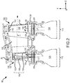
- FIG. 2 schematically shows, by example, a portion of an engine section 80 , which is illustrated as a turbine section 28 of gas turbine engine 20 . It will be understood that the cooling systems in the present disclosure are not limited to the turbine section, and could extend to other sections of the gas turbine engine 20 , including but not limited to compressor section 24 .
- Engine section 80 may include alternating rows of blades 101 and vanes 102 comprising airfoils that extend into the core flow path C.
- the rotor assemblies can carry a plurality of rotating blades 101
- each vane assembly can carry a plurality of vanes 102 that extend into the core flow path C.
- Blades 101 create or extract energy (in the form of pressure) from the core airflow that is communicated through the gas turbine engine 20 along the core flow path C.
- Vanes 102 direct the core airflow to the blades 101 to either add or extract energy.
- Vanes 102 may be arranged circumferentially about engine central longitudinal axis A-A′.
- a set of blades 101 may be coupled about a circumference of a generally circular disk 104 , which may be disposed radially inward of core flow path C.
- Disk 104 with blades 101 may comprise a rotor assembly 110 configured to rotate about engine central longitudinal axis A-A′.
- Blades 101 and vanes 102 may generally be referred to as airfoils 100 .
- Each airfoil 100 illustrated as blade 101 , has an airfoil body 120 having a leading edge 124 facing a forward direction in the gas turbine engine and a trailing edge 126 facing an aft direction.
- An airfoil 100 may include a pressure side wall (i.e.
- Each blade 101 may include a platform 130 and/or a root 132 disposed at an inner diameter 140 of an airfoil body 120 .
- the airfoil body 120 may extend radially outward from platform 130 and/or root 132 at inner diameter 140 to a tip region 142 .
- Airfoil body 120 , platform 130 and root 132 may be integrally formed.
- the term “integrated” or “integral” may include forming one, single continuous piece. Casting may be used to form airfoils 100 of FIG. 2 .
- an airfoil 100 may be an internally cooled component of gas turbine engine 20 .
- An airfoil 100 may comprise a cooling system 150 having at least one internal cooling passage 158 , i.e., at least one internal airflow path.
- cooling system 150 may be configured to provide multiple airflow paths to deliver cooling airflow to an airfoil 100 .
- the airflow may originate from any suitable source in gas turbine engine 20 .
- the airflow may comprise air received from a compressor section of gas turbine engine 20 .
- airfoil body 120 may define an internal cooling passage 158 , which directs airflow and further defines airflow path E.
- Airflow path E defined by cooling passage 158 of airfoil body 120 is oriented generally in a direction radially outward from platform 130 and root 132 toward tip region 142 (i.e., a radial direction when airfoil 100 is installed in a turbine).
- Airfoil 100 may contain multiple cooling passages or airflow paths, such as airflow path E and airflow path F, oriented in various directions.
- airflow path E may be directed through airfoil 100 and may exit at or near the tip region 142 of airfoil 100 through a plurality of holes or outlets 152 defined in the tip region 142 of airfoil 100 .
- Airflow path F may be directed through airfoil 100 and may exit the trailing edge 126 of airfoil 100 through a plurality of holes or outlets 154 defined in the trailing edge 126 of airfoil 100 .
- casting may be used to form airfoils 100 .
- Casting core 160 may be used in casting airfoil 100 to define internal features, such as cooling passage 158 as well as outlets 152 and outlets 154 of airfoil 100 .
- an internal cooling configuration of an airfoil 100 is shown as defined on a casting core 160 , in accordance with various embodiments.
- Casting core 160 may be a negative of the cooling features of airfoil 100 .
- airfoil cooling features such as protrusions or pedestals, may appear as indentations and/or passages formed on a casting core 160 .
- the cooling features may protrude from and/or across an internal passage.
- one or more pedestals 200 ( FIGS. 4A and 4B ) inside the airfoil 100 may be defined by a plurality of apertures 180 in casting core 160 ( FIGS.
- cooling passages 210 ( FIGS. 4A and 4B ) defined in the airfoil 100 are occupied by casting protrusions 190 of casting core 160 ( FIGS. 3A and 3B ).
- casting core 160 may be configured as a negative of the internal passages of airfoil 100 .
- Casting core 160 may comprise a core body 162 having a tip region 164 at a radially outer edge of core body 162 .
- Core body 162 of casting core 160 may comprise a leading edge 170 and a trailing edge 172 .
- Tip region 164 may extend between the leading edge 170 and the trailing edge 172 at the radially outer edge of casting core 160 .
- Core body 162 may define one or more cooling passages 158 within airfoil 100 .
- Casting core 160 may comprise a tip comb 166 extending from tip region 164 .
- the tip comb 166 of casting core 160 may be integrally formed with the core body 162 of casting core 160 .
- casting core 160 including core body 162 and tip comb 166 may comprise a unitary structure having a uniform material.
- casting core 160 including core body 162 and tip comb 166 may comprise a ceramic.
- Casting core 160 may include other materials, such as polymer, metal, metal alloys, and/or ceramic matrix composites, among others.
- Tip comb 166 may extend beyond a tip region 142 of airfoil 100 during the casting process to define outlets 152 ( FIGS. 4A and 4B ).
- casting core 160 may extend beyond trailing edge 126 of airfoil 100 during the casting process to define outlets 154 at trailing edge 126 ( FIG. 2 ).
- Tip comb 166 may comprise a plurality of casting protrusions 190 defining a plurality of apertures 180 therebetween.
- tip comb 166 may comprise a first casting protrusion 190 a and a second casting protrusion 190 b .
- the first casting protrusion 190 a and second casting protrusion 190 b may define aperture 180 , which may have a tapered geometry.
- Aperture 180 may have a first width W 1 at a proximal end 182 and a second width W 2 at a distal end 184 .
- the first width W 1 of aperture 180 may be different than the second width W 2 of aperture 180 .
- the second width W 2 of the aperture 180 may be less than the first width W 2 .
- apertures 180 may have a tapered shape that converge toward a distal end 184 , i.e., toward tip region 164 .
- Each of the casting protrusions 190 may have a first width W 3 at a proximal end 192 and a second width W 4 at a distal end 194 .
- the first width W 3 of a casting protrusion 190 may be different than the second width W 4 of casting protrusion 190 .
- the second width W 4 of casting protrusion 190 may be greater than the first width W 3 .
- casting protrusions 190 may have a tapered shape that diverge toward a distal end 194 , i.e., toward tip region 164 .
- casting core 160 may be placed in a mold, and the material to form the airfoil 100 may be deposited in the mold.
- Airfoil 100 may be made from a material different from the material of casting core 160 , such as a metal or metal alloy.
- Airfoil 100 may be made from an austenitic nickel-chromium-based alloy, or other materials capable of withstanding exhaust temperatures.
- Casting core 160 may be removed from the airfoil 100 , leaving a cavity, such as cooling passage 158 , with the desired internal cooling features, such as pedestals 200 and cooling passages 210 within airfoil 100 ( FIGS. 4A and 4B ).
- FIGS. 4A and 4B a tip region of an airfoil 100 formed using casting core 160 is shown, in accordance with various embodiments.
- pedestals 200 inside airfoil 100 may be defined by apertures 180 in casting core 160 ( FIGS. 3A and 3B ).
- cooling passages 210 formed through airfoil 100 may be occupied by casting protrusions 190 of casting core 160 ( FIGS. 3A and 3B ) during the manufacturing of airfoil 100 .
- Airfoil body 120 of airfoil 100 may define an airflow path E formed by casting core 160 .
- Airfoil body 120 may include a pressure side wall 240 (i.e. having a generally concave surface) and a suction side wall 242 (i.e. having a generally convex surface) joined together at the respective trailing edge 126 and leading edge 124 .
- a tip shelf 250 may be formed in tip region 142 of airfoil body 120 .
- the tip shelf 250 follows the curvature of the airfoil and is angled to face towards the suction side of the airfoil.
- tip shelf 250 may comprises a suction side wall portion and a radially outward wall portion.
- the tip shelf 250 may be angled to face towards the pressure side of the airfoil and thus tip shelf 250 may comprise a pressure side wall portion 252 and a radially outward wall portion 254 .
- Tip shelf 250 may be manufactured by subtractive techniques, drilling, milling, machining or other suitable process.
- tip shelf 250 may be formed after removing casting core 160 .
- the step of forming tip shelf 250 may also form outlets 152 in the surface of tip shelf 250 .
- tip region 142 may comprise a plurality of pedestals 200 defining a plurality of cooling passages 210 therebetween.
- tip region 142 may comprise a first pedestal 200 a and a second pedestal 200 b disposed in the airflow path E at the tip region 142 .
- First pedestal 200 a and second pedestal 200 b may define a cooling passage 210 having a proximal end 212 and a distal end 214 .
- the proximal end 212 of the cooling passage 210 may have a first width W 5 and the distal end 214 of the cooling passage 210 may have a second width W 6 .
- the first width W 5 of cooling passage 210 may be different than the second width W 6 .
- the first width W 5 of cooling passage 210 may be greater than the second width W 6 .
- cooling passage 210 may have a tapered shape that diverges toward a distal end 214 , i.e., toward tip region 142 .
- the casting protrusions 190 of casting core 160 define cooling passages 210 of airfoil 100 ( FIGS. 4A and 4B ).
- first width W 3 of casting protrusions 190 may be the same as first width W 5 of second width W 6 .
- Second width W 4 of casting protrusions 190 may be the same as second width W 6 of second width W 6 .
- a width of apertures 180 of casting core 160 may be the same as the width of pedestals 200 of airfoil 100 ( FIGS. 4A and 4B ).
- Cooling passage 210 may comprise an outlet 152 formed in the tip shelf 250 . Cooling passage 210 may be directed radially outward and toward the pressure side wall portion 252 of tip shelf 250 . The various widths of cooling passages 210 may be selected to control the flow rate and direction of airflow path E through the cooling passages 210 and the flow rate and direction of airflow path E at the outlets 152 . Pressure side wall portion 252 of tip shelf 250 may receive a cooling airflow, i.e., airflow path E, from cooling passages 210 . This width of outlets 152 , i.e., the second width W 6 of cooling passages 210 , may be greater than the width of typical outlets formed by, for example, drilling. The greater width outlets 152 allows coatings to be applied to tip shelf 250 , such as to pressure side wall portion 252 and/or radially outward wall portion 254 without undesirably covering or clogging the outlets 152 with a coating material.
- This width of outlets 152 i.e., the second
- the method 300 may include the step of forming a casting core comprising a tip comb integral with a core body (step 302 ).
- the casting core may comprise a first material.
- the method 300 may include the steps of disposing a mold around the casting core (step 304 ), casting a second material around at least a portion of the casting core to form the airfoil (step 306 ), removing the casting core (step 308 ), and removing a portion of the second material from a tip region of the airfoil to form an outlet of the cooling passage (step 310 ).
- the first material i.e., the material of the casting core 160
- the second material i.e., the material of the airfoil 100
- Step 304 may comprise leaving a portion of the tip comb 166 extending beyond a tip region 142 of the airfoil 100 .
- the tip comb 166 may be configured to form cooling passages 210 in the tip region 142 of the airfoil 100 .
- Step 308 may further comprise the removing the casting core 160 to form one or more cooling passages 210 within the airfoil 100 .
- Step 306 may comprise casting the second material to form at least one pedestal 200 .
- the cooling passages 210 are separated by the at least one pedestal 200 .
- the cooling passages 210 comprise a tapered geometry which diverges toward the outlet 152 of the cooling passage 210 .
- references to “various embodiments”, “one embodiment”, “an embodiment”, “an example embodiment”, etc. indicate that the embodiment described may include a particular feature, structure, or characteristic, but every embodiment may not necessarily include the particular feature, structure, or characteristic. Moreover, such phrases are not necessarily referring to the same embodiment. Further, when a particular feature, structure, or characteristic is described in connection with an embodiment, it is submitted that it is within the knowledge of one skilled in the art to affect such feature, structure, or characteristic in connection with other embodiments whether or not explicitly described. After reading the description, it will be apparent to one skilled in the relevant art(s) how to implement the disclosure in alternative embodiments.
Landscapes
- Engineering & Computer Science (AREA)
- Mechanical Engineering (AREA)
- General Engineering & Computer Science (AREA)
- Physics & Mathematics (AREA)
- Thermal Sciences (AREA)
- Turbine Rotor Nozzle Sealing (AREA)
- Molds, Cores, And Manufacturing Methods Thereof (AREA)
Abstract
Description
Claims (2)
Priority Applications (2)
| Application Number | Priority Date | Filing Date | Title |
|---|---|---|---|
| US15/623,787 US10822959B2 (en) | 2017-06-15 | 2017-06-15 | Blade tip cooling |
| EP18166988.8A EP3415716B1 (en) | 2017-06-15 | 2018-04-12 | Blade tip cooling |
Applications Claiming Priority (1)
| Application Number | Priority Date | Filing Date | Title |
|---|---|---|---|
| US15/623,787 US10822959B2 (en) | 2017-06-15 | 2017-06-15 | Blade tip cooling |
Publications (2)
| Publication Number | Publication Date |
|---|---|
| US20180363469A1 US20180363469A1 (en) | 2018-12-20 |
| US10822959B2 true US10822959B2 (en) | 2020-11-03 |
Family
ID=61972036
Family Applications (1)
| Application Number | Title | Priority Date | Filing Date |
|---|---|---|---|
| US15/623,787 Active 2038-11-02 US10822959B2 (en) | 2017-06-15 | 2017-06-15 | Blade tip cooling |
Country Status (2)
| Country | Link |
|---|---|
| US (1) | US10822959B2 (en) |
| EP (1) | EP3415716B1 (en) |
Citations (15)
| Publication number | Priority date | Publication date | Assignee | Title |
|---|---|---|---|---|
| US6036441A (en) | 1998-11-16 | 2000-03-14 | General Electric Company | Series impingement cooled airfoil |
| US20030059304A1 (en) * | 2001-09-27 | 2003-03-27 | Leeke Leslie Eugene | Ramped tip shelf blade |
| US6652235B1 (en) * | 2002-05-31 | 2003-11-25 | General Electric Company | Method and apparatus for reducing turbine blade tip region temperatures |
| US20040022633A1 (en) | 2002-07-31 | 2004-02-05 | Kraft Robert J. | Insulated cooling passageway for cooling a shroud of a turbine blade |
| EP1441107A2 (en) | 2003-01-24 | 2004-07-28 | United Technologies Corporation | Turbine blade |
| US20070128033A1 (en) * | 2005-12-05 | 2007-06-07 | General Electric Company | Blunt tip turbine blade |
| US20080131278A1 (en) * | 2006-11-30 | 2008-06-05 | Victor Hugo Silva Correia | Turbine blades and turbine blade cooling systems and methods |
| US20080131285A1 (en) | 2006-11-30 | 2008-06-05 | United Technologies Corporation | RMC-defined tip blowing slots for turbine blades |
| EP1935532A1 (en) | 2006-12-19 | 2008-06-25 | General Electric Company | Cluster bridged casting core |
| EP1952911A1 (en) | 2007-01-30 | 2008-08-06 | United Technologies Corporation | Turbine blade, casting core and method |
| US20110176929A1 (en) * | 2010-01-21 | 2011-07-21 | General Electric Company | System for cooling turbine blades |
| US20140271226A1 (en) * | 2012-10-31 | 2014-09-18 | General Electric Company | Turbine Blade Tip With Tip Shelf Diffuser Holes |
| US20160230564A1 (en) | 2015-02-11 | 2016-08-11 | United Technologies Corporation | Blade tip cooling arrangement |
| US9422817B2 (en) | 2012-05-31 | 2016-08-23 | United Technologies Corporation | Turbine blade root with microcircuit cooling passages |
| US9429027B2 (en) | 2012-04-05 | 2016-08-30 | United Technologies Corporation | Turbine airfoil tip shelf and squealer pocket cooling |
-
2017
- 2017-06-15 US US15/623,787 patent/US10822959B2/en active Active
-
2018
- 2018-04-12 EP EP18166988.8A patent/EP3415716B1/en active Active
Patent Citations (15)
| Publication number | Priority date | Publication date | Assignee | Title |
|---|---|---|---|---|
| US6036441A (en) | 1998-11-16 | 2000-03-14 | General Electric Company | Series impingement cooled airfoil |
| US20030059304A1 (en) * | 2001-09-27 | 2003-03-27 | Leeke Leslie Eugene | Ramped tip shelf blade |
| US6652235B1 (en) * | 2002-05-31 | 2003-11-25 | General Electric Company | Method and apparatus for reducing turbine blade tip region temperatures |
| US20040022633A1 (en) | 2002-07-31 | 2004-02-05 | Kraft Robert J. | Insulated cooling passageway for cooling a shroud of a turbine blade |
| EP1441107A2 (en) | 2003-01-24 | 2004-07-28 | United Technologies Corporation | Turbine blade |
| US20070128033A1 (en) * | 2005-12-05 | 2007-06-07 | General Electric Company | Blunt tip turbine blade |
| US20080131278A1 (en) * | 2006-11-30 | 2008-06-05 | Victor Hugo Silva Correia | Turbine blades and turbine blade cooling systems and methods |
| US20080131285A1 (en) | 2006-11-30 | 2008-06-05 | United Technologies Corporation | RMC-defined tip blowing slots for turbine blades |
| EP1935532A1 (en) | 2006-12-19 | 2008-06-25 | General Electric Company | Cluster bridged casting core |
| EP1952911A1 (en) | 2007-01-30 | 2008-08-06 | United Technologies Corporation | Turbine blade, casting core and method |
| US20110176929A1 (en) * | 2010-01-21 | 2011-07-21 | General Electric Company | System for cooling turbine blades |
| US9429027B2 (en) | 2012-04-05 | 2016-08-30 | United Technologies Corporation | Turbine airfoil tip shelf and squealer pocket cooling |
| US9422817B2 (en) | 2012-05-31 | 2016-08-23 | United Technologies Corporation | Turbine blade root with microcircuit cooling passages |
| US20140271226A1 (en) * | 2012-10-31 | 2014-09-18 | General Electric Company | Turbine Blade Tip With Tip Shelf Diffuser Holes |
| US20160230564A1 (en) | 2015-02-11 | 2016-08-11 | United Technologies Corporation | Blade tip cooling arrangement |
Non-Patent Citations (1)
| Title |
|---|
| European Patent Office, European Search Report dated Jun. 1, 2018 in Application No. 18166988.8-1006. |
Also Published As
| Publication number | Publication date |
|---|---|
| EP3415716B1 (en) | 2020-05-27 |
| US20180363469A1 (en) | 2018-12-20 |
| EP3415716A1 (en) | 2018-12-19 |
Similar Documents
| Publication | Publication Date | Title |
|---|---|---|
| EP3020923B1 (en) | Cooled turbine blade | |
| EP3396112B1 (en) | Airfoil platform cooling channels | |
| EP3477058B1 (en) | Airfoil cooling circuit | |
| EP2900961A1 (en) | Gas turbine engine airfoil cooling circuit | |
| EP3421723A2 (en) | Airfoils and corresponding method of manufacturing | |
| WO2014047022A1 (en) | Gas turbine engine component cooling circuit | |
| US10934845B2 (en) | Dual cooling airflow to blades | |
| EP3379032B1 (en) | Cooled airfoil and corresponding gas turbine engine | |
| US10215037B2 (en) | Contoured retaining ring | |
| US20240352942A1 (en) | Tandem blade rotor disk | |
| EP3412868B1 (en) | Vane with adjustable flow split platform cooling for gas turbine engine | |
| US9957820B2 (en) | Heat shield for a vane assembly of a gas turbine engine | |
| US10822959B2 (en) | Blade tip cooling | |
| EP3477053B1 (en) | Gas turbine airfoil cooling circuit and method of manufacturing | |
| US20200291806A1 (en) | Boas and methods of making a boas having fatigue resistant cooling inlets | |
| EP3293361B1 (en) | Gas turbine engine and corresponding method of manufacturing |
Legal Events
| Date | Code | Title | Description |
|---|---|---|---|
| AS | Assignment |
Owner name: UNITED TECHNOLOGIES CORPORATION, CONNECTICUT Free format text: ASSIGNMENT OF ASSIGNORS INTEREST;ASSIGNORS:MOLONY, EVAN P.;CLUM, CAREY;MONGILLO, DOMINIC J.;AND OTHERS;REEL/FRAME:042822/0173 Effective date: 20170614 |
|
| STPP | Information on status: patent application and granting procedure in general |
Free format text: DOCKETED NEW CASE - READY FOR EXAMINATION |
|
| STPP | Information on status: patent application and granting procedure in general |
Free format text: NON FINAL ACTION MAILED |
|
| STPP | Information on status: patent application and granting procedure in general |
Free format text: RESPONSE TO NON-FINAL OFFICE ACTION ENTERED AND FORWARDED TO EXAMINER |
|
| STPP | Information on status: patent application and granting procedure in general |
Free format text: PRE-INTERVIEW COMMUNICATION MAILED |
|
| STPP | Information on status: patent application and granting procedure in general |
Free format text: RESPONSE TO NON-FINAL OFFICE ACTION ENTERED AND FORWARDED TO EXAMINER |
|
| STPP | Information on status: patent application and granting procedure in general |
Free format text: FINAL REJECTION MAILED |
|
| AS | Assignment |
Owner name: RAYTHEON TECHNOLOGIES CORPORATION, MASSACHUSETTS Free format text: CHANGE OF NAME;ASSIGNOR:UNITED TECHNOLOGIES CORPORATION;REEL/FRAME:054062/0001 Effective date: 20200403 |
|
| AS | Assignment |
Owner name: RAYTHEON TECHNOLOGIES CORPORATION, CONNECTICUT Free format text: CHANGE OF NAME;ASSIGNOR:UNITED TECHNOLOGIES CORPORATION;REEL/FRAME:053890/0525 Effective date: 20200403 |
|
| STPP | Information on status: patent application and granting procedure in general |
Free format text: PUBLICATIONS -- ISSUE FEE PAYMENT VERIFIED |
|
| STCF | Information on status: patent grant |
Free format text: PATENTED CASE |
|
| AS | Assignment |
Owner name: RAYTHEON TECHNOLOGIES CORPORATION, CONNECTICUT Free format text: CORRECTIVE ASSIGNMENT TO CORRECT THE AND REMOVE PATENT APPLICATION NUMBER 11886281 AND ADD PATENT APPLICATION NUMBER 14846874. TO CORRECT THE RECEIVING PARTY ADDRESS PREVIOUSLY RECORDED AT REEL: 054062 FRAME: 0001. ASSIGNOR(S) HEREBY CONFIRMS THE CHANGE OF ADDRESS;ASSIGNOR:UNITED TECHNOLOGIES CORPORATION;REEL/FRAME:055659/0001 Effective date: 20200403 |
|
| CC | Certificate of correction | ||
| AS | Assignment |
Owner name: RTX CORPORATION, CONNECTICUT Free format text: CHANGE OF NAME;ASSIGNOR:RAYTHEON TECHNOLOGIES CORPORATION;REEL/FRAME:064714/0001 Effective date: 20230714 |
|
| MAFP | Maintenance fee payment |
Free format text: PAYMENT OF MAINTENANCE FEE, 4TH YEAR, LARGE ENTITY (ORIGINAL EVENT CODE: M1551); ENTITY STATUS OF PATENT OWNER: LARGE ENTITY Year of fee payment: 4 |