EP3396112B1 - Airfoil platform cooling channels - Google Patents
Airfoil platform cooling channels Download PDFInfo
- Publication number
- EP3396112B1 EP3396112B1 EP18169064.5A EP18169064A EP3396112B1 EP 3396112 B1 EP3396112 B1 EP 3396112B1 EP 18169064 A EP18169064 A EP 18169064A EP 3396112 B1 EP3396112 B1 EP 3396112B1
- Authority
- EP
- European Patent Office
- Prior art keywords
- platform
- airfoil
- mating surface
- channel
- airflow
- Prior art date
- Legal status (The legal status is an assumption and is not a legal conclusion. Google has not performed a legal analysis and makes no representation as to the accuracy of the status listed.)
- Active
Links
- 238000001816 cooling Methods 0.000 title claims description 126
- 230000013011 mating Effects 0.000 claims description 65
- 239000007789 gas Substances 0.000 description 37
- 238000000034 method Methods 0.000 description 12
- 230000008901 benefit Effects 0.000 description 8
- 230000008569 process Effects 0.000 description 5
- 239000000567 combustion gas Substances 0.000 description 4
- 239000000284 extract Substances 0.000 description 3
- 239000002826 coolant Substances 0.000 description 2
- 230000008878 coupling Effects 0.000 description 2
- 238000010168 coupling process Methods 0.000 description 2
- 238000005859 coupling reaction Methods 0.000 description 2
- 238000009760 electrical discharge machining Methods 0.000 description 2
- 239000012530 fluid Substances 0.000 description 2
- 239000000446 fuel Substances 0.000 description 2
- 238000003754 machining Methods 0.000 description 2
- 230000003068 static effect Effects 0.000 description 2
- 239000000654 additive Substances 0.000 description 1
- 230000000996 additive effect Effects 0.000 description 1
- 230000000712 assembly Effects 0.000 description 1
- 238000000429 assembly Methods 0.000 description 1
- 238000005266 casting Methods 0.000 description 1
- 230000008859 change Effects 0.000 description 1
- 238000004891 communication Methods 0.000 description 1
- 238000009734 composite fabrication Methods 0.000 description 1
- 230000006835 compression Effects 0.000 description 1
- 238000007906 compression Methods 0.000 description 1
- 238000005553 drilling Methods 0.000 description 1
- 238000005242 forging Methods 0.000 description 1
- 230000012447 hatching Effects 0.000 description 1
- 238000001746 injection moulding Methods 0.000 description 1
- 238000004519 manufacturing process Methods 0.000 description 1
- 239000000463 material Substances 0.000 description 1
- 238000003801 milling Methods 0.000 description 1
- 238000010926 purge Methods 0.000 description 1
- 230000009467 reduction Effects 0.000 description 1
- 230000003252 repetitive effect Effects 0.000 description 1
- 230000004044 response Effects 0.000 description 1
- 239000000126 substance Substances 0.000 description 1
- 238000005382 thermal cycling Methods 0.000 description 1
Images


Classifications
-
- F—MECHANICAL ENGINEERING; LIGHTING; HEATING; WEAPONS; BLASTING
- F01—MACHINES OR ENGINES IN GENERAL; ENGINE PLANTS IN GENERAL; STEAM ENGINES
- F01D—NON-POSITIVE DISPLACEMENT MACHINES OR ENGINES, e.g. STEAM TURBINES
- F01D25/00—Component parts, details, or accessories, not provided for in, or of interest apart from, other groups
- F01D25/08—Cooling; Heating; Heat-insulation
- F01D25/12—Cooling
-
- F—MECHANICAL ENGINEERING; LIGHTING; HEATING; WEAPONS; BLASTING
- F01—MACHINES OR ENGINES IN GENERAL; ENGINE PLANTS IN GENERAL; STEAM ENGINES
- F01D—NON-POSITIVE DISPLACEMENT MACHINES OR ENGINES, e.g. STEAM TURBINES
- F01D5/00—Blades; Blade-carrying members; Heating, heat-insulating, cooling or antivibration means on the blades or the members
- F01D5/12—Blades
- F01D5/14—Form or construction
- F01D5/18—Hollow blades, i.e. blades with cooling or heating channels or cavities; Heating, heat-insulating or cooling means on blades
- F01D5/187—Convection cooling
-
- F—MECHANICAL ENGINEERING; LIGHTING; HEATING; WEAPONS; BLASTING
- F01—MACHINES OR ENGINES IN GENERAL; ENGINE PLANTS IN GENERAL; STEAM ENGINES
- F01D—NON-POSITIVE DISPLACEMENT MACHINES OR ENGINES, e.g. STEAM TURBINES
- F01D11/00—Preventing or minimising internal leakage of working-fluid, e.g. between stages
- F01D11/005—Sealing means between non relatively rotating elements
- F01D11/006—Sealing the gap between rotor blades or blades and rotor
-
- F—MECHANICAL ENGINEERING; LIGHTING; HEATING; WEAPONS; BLASTING
- F01—MACHINES OR ENGINES IN GENERAL; ENGINE PLANTS IN GENERAL; STEAM ENGINES
- F01D—NON-POSITIVE DISPLACEMENT MACHINES OR ENGINES, e.g. STEAM TURBINES
- F01D11/00—Preventing or minimising internal leakage of working-fluid, e.g. between stages
- F01D11/02—Preventing or minimising internal leakage of working-fluid, e.g. between stages by non-contact sealings, e.g. of labyrinth type
- F01D11/04—Preventing or minimising internal leakage of working-fluid, e.g. between stages by non-contact sealings, e.g. of labyrinth type using sealing fluid, e.g. steam
-
- F—MECHANICAL ENGINEERING; LIGHTING; HEATING; WEAPONS; BLASTING
- F01—MACHINES OR ENGINES IN GENERAL; ENGINE PLANTS IN GENERAL; STEAM ENGINES
- F01D—NON-POSITIVE DISPLACEMENT MACHINES OR ENGINES, e.g. STEAM TURBINES
- F01D5/00—Blades; Blade-carrying members; Heating, heat-insulating, cooling or antivibration means on the blades or the members
- F01D5/30—Fixing blades to rotors; Blade roots ; Blade spacers
- F01D5/3007—Fixing blades to rotors; Blade roots ; Blade spacers of axial insertion type
-
- F—MECHANICAL ENGINEERING; LIGHTING; HEATING; WEAPONS; BLASTING
- F01—MACHINES OR ENGINES IN GENERAL; ENGINE PLANTS IN GENERAL; STEAM ENGINES
- F01D—NON-POSITIVE DISPLACEMENT MACHINES OR ENGINES, e.g. STEAM TURBINES
- F01D5/00—Blades; Blade-carrying members; Heating, heat-insulating, cooling or antivibration means on the blades or the members
- F01D5/02—Blade-carrying members, e.g. rotors
- F01D5/08—Heating, heat-insulating or cooling means
- F01D5/081—Cooling fluid being directed on the side of the rotor disc or at the roots of the blades
- F01D5/082—Cooling fluid being directed on the side of the rotor disc or at the roots of the blades on the side of the rotor disc
-
- F—MECHANICAL ENGINEERING; LIGHTING; HEATING; WEAPONS; BLASTING
- F05—INDEXING SCHEMES RELATING TO ENGINES OR PUMPS IN VARIOUS SUBCLASSES OF CLASSES F01-F04
- F05D—INDEXING SCHEME FOR ASPECTS RELATING TO NON-POSITIVE-DISPLACEMENT MACHINES OR ENGINES, GAS-TURBINES OR JET-PROPULSION PLANTS
- F05D2220/00—Application
- F05D2220/30—Application in turbines
- F05D2220/32—Application in turbines in gas turbines
-
- F—MECHANICAL ENGINEERING; LIGHTING; HEATING; WEAPONS; BLASTING
- F05—INDEXING SCHEMES RELATING TO ENGINES OR PUMPS IN VARIOUS SUBCLASSES OF CLASSES F01-F04
- F05D—INDEXING SCHEME FOR ASPECTS RELATING TO NON-POSITIVE-DISPLACEMENT MACHINES OR ENGINES, GAS-TURBINES OR JET-PROPULSION PLANTS
- F05D2240/00—Components
- F05D2240/80—Platforms for stationary or moving blades
- F05D2240/81—Cooled platforms
-
- F—MECHANICAL ENGINEERING; LIGHTING; HEATING; WEAPONS; BLASTING
- F05—INDEXING SCHEMES RELATING TO ENGINES OR PUMPS IN VARIOUS SUBCLASSES OF CLASSES F01-F04
- F05D—INDEXING SCHEME FOR ASPECTS RELATING TO NON-POSITIVE-DISPLACEMENT MACHINES OR ENGINES, GAS-TURBINES OR JET-PROPULSION PLANTS
- F05D2250/00—Geometry
- F05D2250/30—Arrangement of components
- F05D2250/31—Arrangement of components according to the direction of their main axis or their axis of rotation
- F05D2250/314—Arrangement of components according to the direction of their main axis or their axis of rotation the axes being inclined in relation to each other
-
- F—MECHANICAL ENGINEERING; LIGHTING; HEATING; WEAPONS; BLASTING
- F05—INDEXING SCHEMES RELATING TO ENGINES OR PUMPS IN VARIOUS SUBCLASSES OF CLASSES F01-F04
- F05D—INDEXING SCHEME FOR ASPECTS RELATING TO NON-POSITIVE-DISPLACEMENT MACHINES OR ENGINES, GAS-TURBINES OR JET-PROPULSION PLANTS
- F05D2260/00—Function
- F05D2260/20—Heat transfer, e.g. cooling
- F05D2260/202—Heat transfer, e.g. cooling by film cooling
-
- Y—GENERAL TAGGING OF NEW TECHNOLOGICAL DEVELOPMENTS; GENERAL TAGGING OF CROSS-SECTIONAL TECHNOLOGIES SPANNING OVER SEVERAL SECTIONS OF THE IPC; TECHNICAL SUBJECTS COVERED BY FORMER USPC CROSS-REFERENCE ART COLLECTIONS [XRACs] AND DIGESTS
- Y02—TECHNOLOGIES OR APPLICATIONS FOR MITIGATION OR ADAPTATION AGAINST CLIMATE CHANGE
- Y02T—CLIMATE CHANGE MITIGATION TECHNOLOGIES RELATED TO TRANSPORTATION
- Y02T50/00—Aeronautics or air transport
- Y02T50/60—Efficient propulsion technologies, e.g. for aircraft
Definitions
- the present disclosure relates to cooling structures for gas turbine engines, and, more specifically, to cooling systems for airfoil platforms.
- a gas turbine engine typically includes a fan section, a compressor section, a combustor section, and a turbine section.
- a fan section may drive air along a bypass flowpath while a compressor section may drive air along a core flowpath.
- air is pressurized in the compressor section and is mixed with fuel and burned in the combustor section to generate hot combustion gases.
- the hot combustion gases flow through the turbine section, which extracts energy from the hot combustion gases to power the compressor section and other gas turbine engine loads.
- the compressor section typically includes low pressure and high pressure compressors, and the turbine section includes low pressure and high pressure turbines.
- the turbine section includes multiple stages of blades and vanes. As fluid flows through the turbine section, the flow causes the blades to rotate about an axis of rotation.
- the vanes, positioned between each row of blades, are used to redirect the flow in order to maximize the power received by the downstream blades.
- Temperatures within the turbine section may be relatively high, as the flow of fluid is received initially from the combustor section of the gas turbine engine. Cooling air may be extracted from the compressor section and used to cool the gas path components. Cooled components may include, for example, rotating blades and stator vanes in the turbine section.
- US 8641377 B1 discloses a turbine rotor blade for an industrial gas turbine engine with a platform cooling circuit.
- EP 2956627 A2 discloses a component for a gas turbine engine having a platform and a cavity, wherein a plurality of cooling holes extends from the cavity to a mate face of the platform.
- WO 2015/112240 A2 discloses a rotor blade including a platform, an airfoil that extends from the platform and a platform cooling passage extending inside of the platform.
- An airfoil assembly as claimed in claim 1 is provided.
- the first channel may extend at least 50% through a chord length of the first platform.
- the outlet may be formed in an aft area of the second mating surface.
- the first channel may be further configured to deliver the cooling airflow to a platform trailing edge of the second platform.
- a length of the first channel may be at least 80% of a chord length of the first platform.
- the cooling airflow may be received by the first airfoil from an airflow path external to the root.
- any reference to attached, fixed, connected, or the like may include permanent, removable, temporary, partial, full, and/or any other possible attachment option.
- Any reference related to fluidic coupling to serve as a conduit for cooling airflow and the like may include permanent, removable, temporary, partial, full, and/or any other possible attachment option.
- any reference to without contact (or similar phrases) may also include reduced contact or minimal contact.
- Cross hatching lines may be used throughout the figures to denote different parts but not necessarily to denote the same or different materials.
- any reference to singular includes plural embodiments, and any reference to more than one component or step may include a singular embodiment or step.
- any reference to attached, fixed, connected or the like may include permanent, removable, temporary, partial, full and/or any other possible attachment option. Additionally, any reference to without contact (or similar phrases) may also include reduced contact or minimal contact.
- aft refers to the direction associated with the exhaust (e.g., the back end) of a gas turbine engine.
- forward refers to the direction associated with the intake (e.g., the front end) of a gas turbine engine.
- distal refers to the direction outward, or generally, away from a reference component.
- proximal refers to a direction inward, or generally, towards the reference component.
- a first component that is "radially outward" of a second component means that the first component is positioned at a greater distance away from the engine central longitudinal axis than the second component.
- a first component that is “radially inward” of a second component means that the first component is positioned closer to the engine central longitudinal axis than the second component.
- a first component that is radially inward of a second component rotates through a circumferentially shorter path than the second component.
- the terminology “radially outward” and “radially inward” may also be used relative to references other than the engine central longitudinal axis.
- a first component that is “radially outward” of a second component means that the first component is positioned at a greater distance away from the engine central longitudinal axis than the second component.
- the present disclosure relates to a cooling system for airfoil platforms.
- Various components of a gas turbine engine including but not limited to airfoils and airfoil platforms of blades and vanes, may be subjected to repetitive thermal cycling under widely ranging temperatures and pressures.
- the airfoils and airfoil platforms may be subjected to relatively extreme operating conditions.
- This disclosure relates to gas turbine engine components having platform cooling circuits.
- Various embodiments enable improved heat transfer coefficients in areas of the airfoil platform exposed to hot gas path air, while using a limited pressure drop to achieve the heat transfer coefficients.
- the cooling system directs a cooling airflow through the airfoil platform and toward a mating surface of an adjacent airfoil platform. A plurality of cooling channels are formed through the platform.
- the cooling holes may extend from a first circumferential side of the platform to a second circumferential side opposite the first circumferential side.
- a cooling airflow may be sourced from the first circumferential side of the platform.
- the cooling airflow may be directed through the cooling channels from the first circumferential side to the second circumferential side of the platform and may exit through outlets defined in a mating surface of the second circumferential side.
- the cooling airflow exiting the mating surface impinges a mating surface of an adjacent airfoil platform, thereby cooling the mating surface of the adjacent platform.
- Gas turbine engine 20 may be a two-spool turbofan that generally incorporates a fan section 22, a compressor section 24, a combustor section 26 and a turbine section 28.
- Alternative engines may include, for example, an augmentor section among other systems or features.
- fan section 22 can drive coolant (e.g., air) along a path of bypass airflow B while compressor section 24 can drive coolant along a path of core airflow C for compression and communication into combustor section 26 then expansion through turbine section 28.
- coolant e.g., air
- compressor section 24 can drive coolant along a path of core airflow C for compression and communication into combustor section 26 then expansion through turbine section 28.
- Gas turbine engine 20 may generally comprise a low speed spool 30 and a high speed spool 32 mounted for rotation about an engine central longitudinal axis A-A' relative to an engine static structure 36 or engine case via several bearing systems 38, 38-1, and 38-2.
- Engine central longitudinal axis A-A' is oriented in the z direction on the provided x-y-z axes.
- various bearing systems 38 at various locations may alternatively or additionally be provided, including for example, bearing system 38, bearing system 38-1, and bearing system 38-2.
- Low speed spool 30 may generally comprise an inner shaft 40 that interconnects a fan 42, a low pressure compressor 44 and a low pressure turbine 46.
- Inner shaft 40 may be connected to fan 42 through a geared architecture 48 that can drive fan 42 at a lower speed than low speed spool 30.
- Geared architecture 48 may comprise a gear assembly 60 enclosed within a gear housing 62.
- Gear assembly 60 couples inner shaft 40 to a rotating fan structure.
- High speed spool 32 may comprise an outer shaft 50 that interconnects a high pressure compressor 52 and high pressure turbine 54.
- a combustor 56 may be located between high pressure compressor 52 and high pressure turbine 54.
- a mid-turbine frame 57 of engine static structure 36 may be located generally between high pressure turbine 54 and low pressure turbine 46.
- Mid-turbine frame 57 may support one or more bearing systems 38 in turbine section 28.
- Inner shaft 40 and outer shaft 50 may be concentric and rotate via bearing systems 38 about the engine central longitudinal axis A-A', which is collinear with their longitudinal axes.
- A-A' the engine central longitudinal axis A-A'
- the core airflow C may be compressed by low pressure compressor 44 then high pressure compressor 52, mixed and burned with fuel in combustor 56, then expanded over high pressure turbine 54 and low pressure turbine 46.
- Turbines 46, 54 rotationally drive the respective low speed spool 30 and high speed spool 32 in response to the expansion.
- Gas turbine engine 20 may be, for example, a high-bypass ratio geared aircraft engine. In various embodiments, the bypass ratio of gas turbine engine 20 may be greater than about six (6). In various embodiments, the bypass ratio of gas turbine engine 20 may be greater than ten (10).
- geared architecture 48 may be an epicyclic gear train, such as a star gear system (sun gear in meshing engagement with a plurality of star gears supported by a carrier and in meshing engagement with a ring gear) or other gear system. Geared architecture 48 may have a gear reduction ratio of greater than about 2.3 and low pressure turbine 46 may have a pressure ratio that is greater than about five (5). In various embodiments, the bypass ratio of gas turbine engine 20 is greater than about ten (10:1).
- the diameter of fan 42 may be significantly larger than that of the low pressure compressor 44, and the low pressure turbine 46 may have a pressure ratio that is greater than about five (5:1).
- Low pressure turbine 46 pressure ratio may be measured prior to inlet of low pressure turbine 46 as related to the pressure at the outlet of low pressure turbine 46 prior to an exhaust nozzle.
- a gas turbine engine may comprise an industrial gas turbine (IGT) or a geared aircraft engine, such as a geared turbofan, or non-geared aircraft engine, such as a turbofan, or may comprise any gas turbine engine as desired.
- IGT industrial gas turbine
- a geared aircraft engine such as a geared turbofan
- non-geared aircraft engine such as a turbofan
- each of low pressure compressor 44, high pressure compressor 52, low pressure turbine 46, and high pressure turbine 54 in gas turbine engine 20 may comprise one or more stages or sets of rotating blades and one or more stages or sets of stationary vanes axially interspersed with the associated blade stages but non-rotating about engine central longitudinal axis A-A'.
- Each compressor stage and turbine stage may comprise multiple interspersed stages of blades 104 and vanes 102. The blades 104 rotate about engine central longitudinal axis A-A', while the vanes 102 remain stationary with respect to engine central longitudinal axis A-A'.
- FIG. 2 schematically shows, by example, a portion of an engine section 110, which is illustrated as a turbine section 28 of gas turbine engine 20. It will be understood that the cooling systems in the present disclosure are not limited to the turbine section, and could extend to other sections of the gas turbine engine 20, including but not limited to compressor section 24.
- Engine section 110 may include alternating rows of blades 104 and vanes 102 (shown schematically) that carry airfoils that extend into the core flow path C.
- the rotor assemblies can carry a plurality of rotating blades 104, while each vane assembly can carry a plurality of vanes 102 that extend into the core flow path C.
- Blades 104 create or extract energy (in the form of pressure) from the core airflow that is communicated through the gas turbine engine 20 along the core flow path C.
- Vanes 102 direct the core airflow to the blades 104 to either add or extract energy.
- Vanes 102 may be arranged circumferentially about engine central longitudinal axis A-A'.
- a set of blades 104 may be coupled about a circumference of a generally circular disk 112, which may be disposed radially inward of core flow path C.
- Disk 112 with blades 104 may comprise an airfoil assembly 114 configured to rotate about engine central longitudinal axis A-A'.
- a cover plate 116 or a minidisk 118 may be coupled to an axial surface of disk 112.
- a cover plate 116 may be coupled to an axially forward surface of disk 112, and a minidisk 118 may be coupled to an axially aft surface of disk 112.
- Blades 104 and vanes 102 may generally be referred to as airfoils 100.
- Each airfoil 100 may include an airfoil body 120, a platform 122, and a root 124.
- Platform 122 may be disposed at an inner diameter of the airfoil body 120 of airfoil 100.
- Root 124 may be disposed at an inner diameter of platform 122, such that platform 122 is disposed between airfoil body 120 and root 124.
- Airfoil body 120, a platform 122, and a root 124 may be integrally formed.
- the term "integrated" or "integral” may include forming one, single continuous piece.
- the airfoil body 120 extends from a radially outer surface 128 (i.e.
- a gas path-facing surface of the platform 122 and the root 124 extends from a radially inner surface 130 (i.e. a non-gas path-facing surface) of the platform 122.
- the radially outer surface 128 of platform 122 is exposed to the hot combustion gases of the core flow path C, whereas the radially inner surface 130 is remote from the core flow path C.
- the root 124 is configured to attach the airfoil 100 to the disk 112 of the airfoil assembly 114, such as within a slot formed in the airfoil assembly 114.
- a cooling system 106 for airfoils 100 may include multiple airflow paths, such as airflow paths E and F, feeding cooling air to the airfoil body 120 and/or the platform 122.
- Airflow paths E and F may comprise cooling airflow.
- the cooling airflow in airflow path E may be referred to as a primary cooling airflow, while the cooling airflow in airflow path F may be referred to as a secondary cooling airflow.
- the cooling airflow airflow paths E and F may originate from any suitable source in gas turbine engine 20.
- the airflow may comprise air received from a compressor section of gas turbine engine 20.
- a primary cooling airflow may be directed along airflow path E to provide primary cooling air, for example, to airfoil body 120 of airfoil 100.
- Airflow path E may communicate the primary cooling airflow, such as compressor bleed airflow, through root 124 to internally cool airfoil body 120 and/or other sections of airfoil 100.
- Airflow path E may be directed axially through minidisk 118 and flow radially outward between minidisk 118 and disk 112. Airflow path E may also be directed radially outward between disk 112 and cover plate 116.
- Airflow path E may be directed into disk 112 and/or root 124 as an internal flow path.
- As an internal flow path airflow path E may extend through at least a portion of the root 124 and into airfoil body 120.
- the primary cooling airflow may be at a higher pressure than surrounding areas within engine section 110, creating a tendency for primary cooling airflow to leak into areas around airflow path E.
- Cooling airflow which escapes airflow path E may be captured by cooling system 106 and used by cooling system 106 as a secondary cooling airflow.
- Airflow path F may flow around an exterior of disk 112, minidisk 118, and cover plate 116, and root 124 of airfoil 100. Airflow path F may be defined between roots 124 of adjacent airfoils 100. Roots 124 may each have a first circumferential side 125 and a second circumferential side 126, where the second circumferential side 126 of a root 124 is opposite to the first circumferential side 125.
- Roots 124 such as first root 124a and second root 124b, of adjacent airfoils 100 may define airflow path F. More specifically, a portion of airflow path F may be defined between a first circumferential side 125 of a second root 124b and a second circumferential side 126 of a first root 124a. Thus, the cooling airflow received by airfoil 100 from airflow path F may be external to the root 124.
- the secondary cooling airflow may be directed along airflow path F to provide a secondary cooling air, for example, to the platform 122 of airfoil 100.
- the secondary cooling airflow of airflow path F may be referred to as a "poor man" airflow.
- Airflow path F may flow into platform 122 through the radially inner surface 130 of platform 122. Airflow path E within root 124 and airfoil body 120 may be fluidly isolated from airflow path F within platform 122.
- FIGS. 3A , 3B and 3C a portion of an airfoil assembly 114 having airfoils 100 is shown, in accordance with various embodiments.
- FIG. 3A two adjacent airfoils 100 are shown with each airfoil having an airfoil body 120 coupled to a platform 122.
- Platforms 122 are positioned radially inward of airfoil bodies 120.
- platforms 122 may be inner diameter platforms of airfoil bodies 120.
- the roots 124 are positioned radially inward of platforms 122, such that a platform 122 is disposed between an airfoil body 120 and a root 124.
- Platforms 122 are positioned circumferentially adjacent each other, such that a first platform 122a is positioned circumferentially adjacent a second platform 122b.
- a plurality of platforms 122 may be positioned circumferentially adjacent such that the plurality of platforms 122 encircles the axis of rotation, i.e, engine central longitudinal axis A-A', of gas turbine engine 20 (see FIGS. 1 and 2 ).
- the plurality of platforms 122 may together form an annular segmented platform, such that each of platforms 122 is considered a platform segment of the annular segmented platform.
- FIG. 3A schematically shows, by example, a portion of an airfoil assembly 114, which is illustrated having a plurality of blades 104. It will be understood that the cooling systems in the present disclosure are not limited to blades, and could extend to vanes and vane platforms of the gas turbine engine 20.
- a platform 122 of an airfoil 100 axially extends between a platform leading edge 140 and a platform trailing edge 142 and circumferentially extends between a first mating surface 144 and a second mating surface 146.
- First mating surface 144 may be at a first circumferential side of the platform 122
- second mating surface 146 may be at a second circumferential side of the platform 122, where the second circumferential side is opposite to the first circumferential side.
- the airfoil body 120 axially extends between a leading edge 150 and a trailing edge 152 and circumferentially extends between a pressure side (i.e. having a generally concave surface) and a suction side (i.e. having a generally convex surface).
- a first platform 122a may be circumferentially adjacent to a second platform 122b.
- a second mating surface 146 of first platform 122a may face a first mating surface 144 of second platform 122b.
- First platform 122a may contact a portion of second platform 122b.
- a second mating surface 146 of first platform 122a may be spaced apart (i.e., in the circumferential direction 154) from the first mating surface 144 of second platform 122b and may define a gap 156 therebetween.
- the cooling system 106 provides cooling airflow to the platforms 122 and discourages gas from core flow path C from being ingested into gap 156.
- airfoils 100 may include a cooling system 106 that includes one or more channels 160 (also referred to as cooling passages) and one or more outlets or cooling holes 162 formed in the platform 122 of an airfoil 100.
- Platform 122 in accordance with a first alternative of the present invention defines a pocket 164 in the radially inner surface 130 of platform 122.
- Adjacent platforms 122 such as first platform 122a and second platform 122b, may each define a portion of a pocket 164.
- a first portion of pocket 164 may be defined at second mating surface 146 of first platform 122a and a second portion of pocket 164 is defined at first mating surface 144 of second platform 122b.
- a pocket 164 may be defined by inner diameter surface 130 of first platform 122a and second platform 122b, and more specifically by the inner diameter surface 130 of first platform 122a proximate second mating surface 146 of the first platform 122a and by the inner diameter surface 130 of second platform 122b proximate first mating surface 144 of the second platform 122b.
- FIG. 3B shows a portion of a pocket 164 defined at second mating surface 146 of a platform 122.
- FIG. 3C shows a portion of a pocket 164 defined at first mating surface 144 of a platform 122.
- Pocket 164 may receive secondary cooling airflow of airflow path F, which flows around root 124, and is captured by pocket 164 as airflow path F flows radially outward and reaches radially inner surface 130 of platform 122, i.e., a pocket surface 168, which may be a portion of radially inner surface 130 defining the pocket 164.
- At least two channels 160 extend through platform 122 from a pocket 164 defined at first mating surface 144 to a second mating surface 146, which is an opposite mating surface to first mating surface 144.
- each channel 160 may include an inlet 166 formed in a pocket surface 168.
- Each channel 160 may include an outlet or cooling hole 162 formed in second mating surface 146.
- Channels 160 may extend completely through platform 122 of airfoil 100 in generally the circumferential direction 154.
- Channels 160 may be formed through platform 122 at various angles relative to the provided the xyz axes and/or the circumferential direction 154.
- FIG. 3A shows channels 160 may be oriented generally in the circumferential direction 154 and may also be angled in the axially aft direction (positive z-direction), for example, relative to the xz-plane.
- Channels 160 are formed in different planes, such that inlets 166 of channels 160 may be defined in pocket surface 168 at different radial, axial and circumferential locations, for example, relative to the yz-plane.
- channels 160 may also have different lengths.
- platform 122 defines a first channel 160a having an outlet 162a formed in the second mating surface 146.
- First channel 160a is formed in a first plane, relative to the x-y-z axes.
- Platform 122 defines a second channel 160b having an outlet 162b formed in the second mating surface 146.
- Second channel 160b is formed in a second plane, relative to the x-y-z axes.
- the plane in which the first channel 160a is formed is different than the plane in which the second channel 160b is formed.
- FIG. 3C shows channels 160 may be angled in the axially aft direction (positive z-direction) or the axially forward direction (negative z-direction) relative to inlets 166.
- FIG. 3C also shows channels 160 may also be angled a the radially direction (y-direction), such as in the radially outward direction (positive y-direction) relative to inlets 166.
- channels 160 may be oriented at various angles relative to inlets 166, pocket 164, second mating surface 146, and/or radially outer surface 128.
- Channels 160 may be parallel or non-parallel and may converge or diverge downstream toward cooling holes 162.
- first channel 160a is oriented in a first direction, relative to the x-y-z axes.
- Second channel 160b is oriented in a second direction, relative to the x-y-z axes.
- the first direction may diverge from the second direction (or converge with the second direction) as the first channel 160a and second channel 160b approach second mating surface 146.
- Channels 160 may direct the secondary cooling airflow of airflow path F through platform 122 and may discharge the secondary cooling airflow through cooling holes 162.
- Secondary cooling airflow shown by airflow path F, flows through inlet 166 into the channels 160 within platform 122, is directed through the channel 160, and exits the channel 160 through cooling hole 162.
- airflow path F through platform 122 may be defined, at least in part, by the pocket 164, inlets 166, channels 160, and cooling holes 162.
- a second mating surface 146 of the first platform 122a faces a first mating surface 144 of the second platform 122b.
- the secondary cooling airflow impinges the first mating surface 144 of the second platform 122b, thereby cooling the first mating surface 144 of the second platform 122b.
- the secondary cooling airflow flows within gap 156 as well as over radially outer surface 128 and platform trailing edge 142 of second platform 122b.
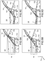
- FIGS. 5A, 5B, 5C and 5D a secondary cooling airflow for various channels 160a-160d and cooling holes 162a-162d are shown, in accordance with various embodiments.
- a first platform 122a is shown delivering secondary cooling airflow to a second platform 122b.
- First platform 122a is illustrated by second mating surface 146 and cooling holes 162a-162d and one of channels 160a-160d.
- Second platform 122b is disposed circumferentially adjacent to first platform 122a and is shown with first mating surface 144 facing first platform 122a.
- FIG. 5A shows a first channel 160a formed in an aft end area of second mating surface 146 of first platform 122a.
- First channel 160a delivers a secondary cooling airflow through first platform 122a, thereby cooling first platform 122a internally.
- Secondary cooling airflow generally flows in a second circumferential direction 154-2 through first channel 160a and is discharged from first channel 160a through first cooling hole 162a.
- Secondary cooling airflow flows into gap 156 and cools first mating surface 144 of the second platform 122b as well as first mating surface 144 of the second platform 122b.
- a portion of secondary cooling airflow, shown by airflow path F flows radially outward, exits gap 156 at radially outer surface 128.
- Secondary cooling airflow flows along radially outer surface 128 of second platform 122b to provide layer of film cooling air over radially outer surface 128. Another portion of secondary cooling airflow flows within gap 156 in an axially aft direction (positive z-direction), along first mating surface 144 and second mating surface 146. This portion of secondary cooling airflow exits gap 156 and generally flows in the second circumferential direction 154-2 along platform trailing edge 142.
- FIGS. 5B, 5C and 5D respectively show a second channel 160b, a third channel 160c, and a fourth channel 160d delivering a secondary cooling airflow through first platform 122a.
- Second channel 160b, third channel 160c, and fourth channel 160d may be formed in the aft area 158 of second mating surface 146 of first platform 122a.
- each of channels 160b-160d may supply secondary cooling airflow to first mating surface 144 of the second platform 122b.
- Secondary cooling airflow is discharged from second channel 160b through second cooling hole 162b, from third channel 160c through third cooling hole 162c, and fourth channel 160d through fourth cooling hole 162d.
- Each of channels 160a-160d may supply secondary cooling airflow to the radially outer surface 128 and/or along platform trailing edge 142 of second platform 122b.
- a position of channels 160a-160d and cooling holes 162a-162d may be configured to direct airflow path F according to the desired cooling flow, for example, to increase or decrease the cooling flow or to change a direction of the cooling flow over the surfaces of second platform 122b.
- Each of channels 160a-160d and cooling holes 162a-162d may direct cooling airflow in a different direction.
- fourth channel 160d having the aft-most cooling hole, i.e., fourth cooling hole 162d may deliver more cooling airflow to platform trailing edge 142 than a channel with a cooling hole located forward of fourth cooling hole 162d.
- the aft-most cooling hole, i.e., fourth cooling hole 162d may deliver more cooling airflow to platform trailing edge 142 than a channel with a cooling hole located forward of fourth cooling hole 162d.
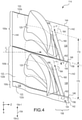
- FIG. 4 a portion of an airfoil assembly 114 having a platform cooling system is shown, in accordance with various embodiments.
- a first blade 100a having first platform 122a, a second blade 100b having second platform 122b, and a portion of a third blade 100c having third platform 122c are illustrated as a portion of airfoil assembly 114.
- First blade 100a and third blade 100c are disposed at opposing circumferential sides of second blade 100b.
- Each of platforms 122a-122c has a first mating surface 144 at a first circumferential side (i.e., toward first circumferential direction 154-2) opposite a second mating surface 146 at a second circumferential side (i.e., toward second circumferential direction 154-1).
- a chord length 170 of each of platform 122a-122c may be measured between first mating surface 144 and second mating surface 146.
- channels 160 are formed completely through each platform 122, and may extend from pocket 164 to second mating surface 146.
- the channel 160 may extend at least 40% through the chord length 170 of a platform 122, or may extend at least 50% through the chord length 170, or may extend at least 60% through the chord length 170.
- a length of channels 160 is shown generally as length 172.
- a channel 160 may have three-dimensional aspects, not shown in FIG. 4 , but shown in FIGS. 3A , 3B and 3C .
- a length 172 may be measured along the channel 160 between the inlet 166 and cooling hole 162 to account for angle of orientation, for example, in radial direction (y-direction).
- the length 172 of channels 160 may be at least 40% of the chord length 170, at least 50% of chord length 170, or at least 60% of chord length 170 of platform 122. Further, as the channels 160 may have an angle of orientation in a radial direction, the length 172 of channels may be 60% of the chord length 170 or greater, or 70% of the chord length 170 or greater, or 80% of the chord length 170 or greater. As the cooling airflow of airflow path F flows internally though platforms 122, the platforms 122 are convectively cooled. A greater length of channels 160 increases the heat transfer between platforms 122 and the cooling airflow in airflow path F thereby increasing cooling effectiveness.
- an airfoil 100 having channels 160 formed through platform 122 may be manufactured by additive manufacturing, injection molding, electrical discharge machining (EDM), composite fabrication, machining, forging, core casting, or other suitable process.
- Channels 160 may be formed by subtractive techniques, drilling, milling, EDM, electrochemical machining (ECM), or other suitable process.
- Channel 160 may have various geometries to tailor the cooling flow through platform 122 and over mating surfaces 144, 146, platform trailing edge 142, and radially outer surface 128.
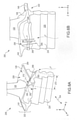
- FIGS. 6A and 6B illustrate perspective views of an airfoil having a platform cooling system, in accordance with various embodiments.
- An airfoil 100 has a platform 222 extending axially between a platform leading edge 140 and a platform trailing edge 142 and extending circumferentially between a first mating surface 244 and a second mating surface 246.
- Airfoil 200 may include a cooling system 206 that includes two or more channels 260 and two or more outlets or cooling holes 262 formed in the platform 222 of an airfoil 200.
- each channel 260 may include an inlet 266 formed in a first circumferential side 225 of root 224.
- the first circumferential side 225 of the root 224 may be proximate the first mating surface 246 of platform 222.
- Each channel 260 includes an outlet or cooling hole 262 formed in second mating surface 246.
- Channels 260 may extend through root 224 and into platform 222 in generally the circumferential direction 154 and radial direction (y-direction). Secondary cooling airflow of airflow path F, which flows around root 124, and is captured at the first circumferential side 225 of root 224 as airflow path F flows radially outward.
- Airflow path F through root 224 and platform 222 may be defined, at least in part, by the root 224, inlets 266, channels 260, and cooling holes 262. As secondary cooling airflow is discharged from cooling holes 262 of platform 222, the secondary cooling airflow impinges a mating surface of an adjacent platform.
- channels 260 are formed completely through a portion of root 224 and platform 222, and may extend from a surface of root 224 to second mating surface 246 of platform 222.
- Each channel 260 may extend at least 40% through the chord length 270 of a platform 222, or may extend at least 50% through the chord length 270, or may extend at least 60% through the chord length 270.
- a length of channels 260 is shown generally as length 272.
- a length 272 may be measured along the channel 260 between the inlet 266 and cooling hole 262 to account for angle of orientation, for example, in radial direction (y-direction).
- the length 272 of channels 260 may be at least 70% of the chord length 270, at least 80% of chord length 270, or at least 90% of chord length 270 of platform 222. Due to the angle of orientation in a radial direction, the length 272 of channels 260 may greater than the chord length 270 of platform 222. In various embodiments, the length 272 of channels 260 may be up to 150% of the chord length 270 of platform 222. As the cooling airflow of airflow path F flows internally though root 242 and platform 222, platform 222 is convectively cooled. A greater length of channels 260 increases the heat transfer between platforms 222 and the cooling airflow in airflow path F thereby increasing cooling effectiveness.
- references to "various embodiments”, “one embodiment”, “an embodiment”, “an example embodiment”, etc. indicate that the embodiment described may include a particular feature, structure, or characteristic, but every embodiment may not necessarily include the particular feature, structure, or characteristic. Moreover, such phrases are not necessarily referring to the same embodiment. Further, when a particular feature, structure, or characteristic is described in connection with an embodiment, it is submitted that it is within the knowledge of one skilled in the art to affect such feature, structure, or characteristic in connection with other embodiments whether or not explicitly described. After reading the description, it will be apparent to one skilled in the relevant art(s) how to implement the disclosure in alternative embodiments.
Description
- The present disclosure relates to cooling structures for gas turbine engines, and, more specifically, to cooling systems for airfoil platforms.
- A gas turbine engine typically includes a fan section, a compressor section, a combustor section, and a turbine section. A fan section may drive air along a bypass flowpath while a compressor section may drive air along a core flowpath. In general, during operation, air is pressurized in the compressor section and is mixed with fuel and burned in the combustor section to generate hot combustion gases. The hot combustion gases flow through the turbine section, which extracts energy from the hot combustion gases to power the compressor section and other gas turbine engine loads. The compressor section typically includes low pressure and high pressure compressors, and the turbine section includes low pressure and high pressure turbines. The turbine section includes multiple stages of blades and vanes. As fluid flows through the turbine section, the flow causes the blades to rotate about an axis of rotation. The vanes, positioned between each row of blades, are used to redirect the flow in order to maximize the power received by the downstream blades.
- Temperatures within the turbine section may be relatively high, as the flow of fluid is received initially from the combustor section of the gas turbine engine. Cooling air may be extracted from the compressor section and used to cool the gas path components. Cooled components may include, for example, rotating blades and stator vanes in the turbine section.
-
US 8641377 B1 discloses a turbine rotor blade for an industrial gas turbine engine with a platform cooling circuit. -
EP 2956627 A2 discloses a component for a gas turbine engine having a platform and a cavity, wherein a plurality of cooling holes extends from the cavity to a mate face of the platform. -
WO 2015/112240 A2 discloses a rotor blade including a platform, an airfoil that extends from the platform and a platform cooling passage extending inside of the platform. - An airfoil assembly as claimed in
claim 1 is provided. - The first channel may extend at least 50% through a chord length of the first platform. The outlet may be formed in an aft area of the second mating surface. The first channel may be further configured to deliver the cooling airflow to a platform trailing edge of the second platform.
- A length of the first channel may be at least 80% of a chord length of the first platform. The cooling airflow may be received by the first airfoil from an airflow path external to the root.
- The foregoing features and elements may be combined in various combinations without exclusivity, unless expressly indicated otherwise. These features and elements as well as the operation thereof will become more apparent in light of the following description and the accompanying drawings. It should be understood, however, the following description and drawings are intended to be exemplary in nature and non-limiting.
- The subject matter of the present disclosure is particularly pointed out and distinctly claimed in the concluding portion of the specification. A more complete understanding of the present disclosure, however, may best be obtained by referring to the detailed description and claims when considered in connection with the figures, wherein like numerals denote like elements.
-
FIG. 1 illustrates a cross-sectional view of an exemplary gas turbine engine, in accordance with various embodiments; -
FIG. 2 illustrates an engine section including example airfoils, such as a blade and a vane of an exemplary gas turbine engine, according to various embodiments; -
FIGS. 3A ,3B and 3C illustrate views of perspective views of airfoils having a platform cooling system, in accordance with various embodiments; -
FIG. 4 illustrates a portion of a airfoil assembly having a platform cooling system, in accordance with various embodiments; -
FIGS. 5A, 5B, 5C and 5D illustrate a cutaway perspective view an airfoil assembly having a platform cooling system, in accordance with various embodiments; and -
FIGS. 6A and 6B illustrate perspective views of an airfoil having a platform cooling system, in accordance with various embodiments. - All ranges and ratio limits disclosed herein may be combined. It is to be understood that unless specifically stated otherwise, references to "a," "an," and/or "the" may include one or more than one and that reference to an item in the singular may also include the item in the plural.
- The detailed description of various embodiments herein makes reference to the accompanying drawings, which show various embodiments by way of illustration. While these various embodiments are described in sufficient detail to enable those skilled in the art to practice the disclosure, it should be understood that other embodiments may be realized and that logical, chemical, and mechanical changes may be made without departing from the scope of the disclosure. Thus, the detailed description herein is presented for purposes of illustration only and not of limitation. For example, the steps recited in any of the method or process descriptions may be executed in any order and are not necessarily limited to the order presented. Furthermore, any reference to singular includes plural embodiments, and any reference to more than one component or step may include a singular embodiment or step. Also, any reference to attached, fixed, connected, or the like may include permanent, removable, temporary, partial, full, and/or any other possible attachment option. Any reference related to fluidic coupling to serve as a conduit for cooling airflow and the like may include permanent, removable, temporary, partial, full, and/or any other possible attachment option. Additionally, any reference to without contact (or similar phrases) may also include reduced contact or minimal contact. Cross hatching lines may be used throughout the figures to denote different parts but not necessarily to denote the same or different materials.
- Any reference to singular includes plural embodiments, and any reference to more than one component or step may include a singular embodiment or step. Also, any reference to attached, fixed, connected or the like may include permanent, removable, temporary, partial, full and/or any other possible attachment option. Additionally, any reference to without contact (or similar phrases) may also include reduced contact or minimal contact.
- As used herein, "aft" refers to the direction associated with the exhaust (e.g., the back end) of a gas turbine engine. As used herein, "forward" refers to the direction associated with the intake (e.g., the front end) of a gas turbine engine. As used herein, "distal" refers to the direction outward, or generally, away from a reference component. As used herein, "proximal" refers to a direction inward, or generally, towards the reference component.
- A first component that is "radially outward" of a second component means that the first component is positioned at a greater distance away from the engine central longitudinal axis than the second component. A first component that is "radially inward" of a second component means that the first component is positioned closer to the engine central longitudinal axis than the second component. In the case of components that rotate circumferentially about the engine central longitudinal axis, a first component that is radially inward of a second component rotates through a circumferentially shorter path than the second component. The terminology "radially outward" and "radially inward" may also be used relative to references other than the engine central longitudinal axis. A first component that is "radially outward" of a second component means that the first component is positioned at a greater distance away from the engine central longitudinal axis than the second component.
- The present disclosure relates to a cooling system for airfoil platforms. Various components of a gas turbine engine, including but not limited to airfoils and airfoil platforms of blades and vanes, may be subjected to repetitive thermal cycling under widely ranging temperatures and pressures. The airfoils and airfoil platforms may be subjected to relatively extreme operating conditions. This disclosure relates to gas turbine engine components having platform cooling circuits. Various embodiments enable improved heat transfer coefficients in areas of the airfoil platform exposed to hot gas path air, while using a limited pressure drop to achieve the heat transfer coefficients. The cooling system directs a cooling airflow through the airfoil platform and toward a mating surface of an adjacent airfoil platform. A plurality of cooling channels are formed through the platform. The cooling holes may extend from a first circumferential side of the platform to a second circumferential side opposite the first circumferential side. A cooling airflow may be sourced from the first circumferential side of the platform. The cooling airflow may be directed through the cooling channels from the first circumferential side to the second circumferential side of the platform and may exit through outlets defined in a mating surface of the second circumferential side. The cooling airflow exiting the mating surface impinges a mating surface of an adjacent airfoil platform, thereby cooling the mating surface of the adjacent platform.
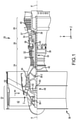
- With reference to
FIG. 1 , agas turbine engine 20 is shown according to various embodiments.Gas turbine engine 20 may be a two-spool turbofan that generally incorporates afan section 22, acompressor section 24, acombustor section 26 and aturbine section 28. Alternative engines may include, for example, an augmentor section among other systems or features. In operation,fan section 22 can drive coolant (e.g., air) along a path of bypass airflow B whilecompressor section 24 can drive coolant along a path of core airflow C for compression and communication intocombustor section 26 then expansion throughturbine section 28. Although depicted as a turbofangas turbine engine 20 herein, it should be understood that the concepts described herein are not limited to use with turbofans as the teachings may be applied to other types of turbine engines including three-spool architectures. -
Gas turbine engine 20 may generally comprise alow speed spool 30 and ahigh speed spool 32 mounted for rotation about an engine central longitudinal axis A-A' relative to an enginestatic structure 36 or engine case viaseveral bearing systems 38, 38-1, and 38-2. Engine central longitudinal axis A-A' is oriented in the z direction on the provided x-y-z axes. It should be understood that various bearingsystems 38 at various locations may alternatively or additionally be provided, including for example, bearingsystem 38, bearing system 38-1, and bearing system 38-2. -
Low speed spool 30 may generally comprise aninner shaft 40 that interconnects afan 42, alow pressure compressor 44 and alow pressure turbine 46.Inner shaft 40 may be connected to fan 42 through a gearedarchitecture 48 that can drivefan 42 at a lower speed thanlow speed spool 30.Geared architecture 48 may comprise agear assembly 60 enclosed within agear housing 62.Gear assembly 60 couplesinner shaft 40 to a rotating fan structure.High speed spool 32 may comprise anouter shaft 50 that interconnects ahigh pressure compressor 52 andhigh pressure turbine 54. Acombustor 56 may be located betweenhigh pressure compressor 52 andhigh pressure turbine 54. Amid-turbine frame 57 of enginestatic structure 36 may be located generally betweenhigh pressure turbine 54 andlow pressure turbine 46.Mid-turbine frame 57 may support one ormore bearing systems 38 inturbine section 28.Inner shaft 40 andouter shaft 50 may be concentric and rotate via bearingsystems 38 about the engine central longitudinal axis A-A', which is collinear with their longitudinal axes. As used herein, a "high pressure" compressor or turbine experiences a higher pressure than a corresponding "low pressure" compressor or turbine. - The core airflow C may be compressed by
low pressure compressor 44 thenhigh pressure compressor 52, mixed and burned with fuel incombustor 56, then expanded overhigh pressure turbine 54 andlow pressure turbine 46.Turbines low speed spool 30 andhigh speed spool 32 in response to the expansion. -
Gas turbine engine 20 may be, for example, a high-bypass ratio geared aircraft engine. In various embodiments, the bypass ratio ofgas turbine engine 20 may be greater than about six (6). In various embodiments, the bypass ratio ofgas turbine engine 20 may be greater than ten (10). In various embodiments, gearedarchitecture 48 may be an epicyclic gear train, such as a star gear system (sun gear in meshing engagement with a plurality of star gears supported by a carrier and in meshing engagement with a ring gear) or other gear system.Geared architecture 48 may have a gear reduction ratio of greater than about 2.3 andlow pressure turbine 46 may have a pressure ratio that is greater than about five (5). In various embodiments, the bypass ratio ofgas turbine engine 20 is greater than about ten (10:1). In various embodiments, the diameter offan 42 may be significantly larger than that of thelow pressure compressor 44, and thelow pressure turbine 46 may have a pressure ratio that is greater than about five (5:1).Low pressure turbine 46 pressure ratio may be measured prior to inlet oflow pressure turbine 46 as related to the pressure at the outlet oflow pressure turbine 46 prior to an exhaust nozzle. It should be understood, however, that the above parameters are exemplary of various embodiments of a suitable geared architecture engine and that the present disclosure contemplates other gas turbine engines including direct drive turbofans. A gas turbine engine may comprise an industrial gas turbine (IGT) or a geared aircraft engine, such as a geared turbofan, or non-geared aircraft engine, such as a turbofan, or may comprise any gas turbine engine as desired. - Referring now to
FIG. 1 and toFIG. 2 , according to various embodiments, each oflow pressure compressor 44,high pressure compressor 52,low pressure turbine 46, andhigh pressure turbine 54 ingas turbine engine 20 may comprise one or more stages or sets of rotating blades and one or more stages or sets of stationary vanes axially interspersed with the associated blade stages but non-rotating about engine central longitudinal axis A-A'. Each compressor stage and turbine stage may comprise multiple interspersed stages ofblades 104 andvanes 102. Theblades 104 rotate about engine central longitudinal axis A-A', while thevanes 102 remain stationary with respect to engine central longitudinal axis A-A'. For example,FIG. 2 schematically shows, by example, a portion of anengine section 110, which is illustrated as aturbine section 28 ofgas turbine engine 20. It will be understood that the cooling systems in the present disclosure are not limited to the turbine section, and could extend to other sections of thegas turbine engine 20, including but not limited tocompressor section 24. -
Engine section 110 may include alternating rows ofblades 104 and vanes 102 (shown schematically) that carry airfoils that extend into the core flow path C. For example, the rotor assemblies can carry a plurality ofrotating blades 104, while each vane assembly can carry a plurality ofvanes 102 that extend into the core flowpath C. Blades 104 create or extract energy (in the form of pressure) from the core airflow that is communicated through thegas turbine engine 20 along the core flowpath C. Vanes 102 direct the core airflow to theblades 104 to either add or extract energy.Vanes 102 may be arranged circumferentially about engine central longitudinal axis A-A'. In various embodiments, a set ofblades 104 may be coupled about a circumference of a generallycircular disk 112, which may be disposed radially inward of core flowpath C. Disk 112 withblades 104 may comprise anairfoil assembly 114 configured to rotate about engine central longitudinal axis A-A'. In various embodiments, acover plate 116 or a minidisk 118 may be coupled to an axial surface ofdisk 112. For example, acover plate 116 may be coupled to an axially forward surface ofdisk 112, and a minidisk 118 may be coupled to an axially aft surface ofdisk 112.Blades 104 andvanes 102 may generally be referred to asairfoils 100. - Each
airfoil 100, illustrated asblades 104, may include anairfoil body 120, aplatform 122, and aroot 124.Platform 122 may be disposed at an inner diameter of theairfoil body 120 ofairfoil 100.Root 124 may be disposed at an inner diameter ofplatform 122, such thatplatform 122 is disposed betweenairfoil body 120 androot 124.Airfoil body 120, aplatform 122, and aroot 124 may be integrally formed. As used herein, the term "integrated" or "integral" may include forming one, single continuous piece. In various embodiments, theairfoil body 120 extends from a radially outer surface 128 (i.e. a gas path-facing surface) of theplatform 122 and theroot 124 extends from a radially inner surface 130 (i.e. a non-gas path-facing surface) of theplatform 122. The radiallyouter surface 128 ofplatform 122 is exposed to the hot combustion gases of the core flow path C, whereas the radiallyinner surface 130 is remote from the core flow path C. Theroot 124 is configured to attach theairfoil 100 to thedisk 112 of theairfoil assembly 114, such as within a slot formed in theairfoil assembly 114. - The
airfoil body 120 andplatform 122 of theairfoils 100 may be subjected to relatively extreme operating conditions. Acooling system 106 forairfoils 100 may include multiple airflow paths, such as airflow paths E and F, feeding cooling air to theairfoil body 120 and/or theplatform 122. Airflow paths E and F may comprise cooling airflow. The cooling airflow in airflow path E may be referred to as a primary cooling airflow, while the cooling airflow in airflow path F may be referred to as a secondary cooling airflow. - The cooling airflow airflow paths E and F may originate from any suitable source in
gas turbine engine 20. For example, the airflow may comprise air received from a compressor section ofgas turbine engine 20. - A primary cooling airflow may be directed along airflow path E to provide primary cooling air, for example, to
airfoil body 120 ofairfoil 100. Airflow path E may communicate the primary cooling airflow, such as compressor bleed airflow, throughroot 124 to internallycool airfoil body 120 and/or other sections ofairfoil 100. Airflow path E may be directed axially throughminidisk 118 and flow radially outward betweenminidisk 118 anddisk 112. Airflow path E may also be directed radially outward betweendisk 112 andcover plate 116. Airflow path E may be directed intodisk 112 and/or root 124 as an internal flow path. As an internal flow path, airflow path E may extend through at least a portion of theroot 124 and intoairfoil body 120. The primary cooling airflow may be at a higher pressure than surrounding areas withinengine section 110, creating a tendency for primary cooling airflow to leak into areas around airflow path E. - Cooling airflow which escapes airflow path E, i.e., a leakage airflow or purge airflow, may be captured by cooling
system 106 and used by coolingsystem 106 as a secondary cooling airflow. Airflow path F may flow around an exterior ofdisk 112, minidisk 118, andcover plate 116, and root 124 ofairfoil 100. Airflow path F may be defined betweenroots 124 ofadjacent airfoils 100.Roots 124 may each have a firstcircumferential side 125 and a secondcircumferential side 126, where the secondcircumferential side 126 of aroot 124 is opposite to the firstcircumferential side 125.Roots 124, such asfirst root 124a andsecond root 124b, ofadjacent airfoils 100 may define airflow path F. More specifically, a portion of airflow path F may be defined between a firstcircumferential side 125 of asecond root 124b and a secondcircumferential side 126 of afirst root 124a. Thus, the cooling airflow received byairfoil 100 from airflow path F may be external to theroot 124. The secondary cooling airflow may be directed along airflow path F to provide a secondary cooling air, for example, to theplatform 122 ofairfoil 100. The secondary cooling airflow of airflow path F may be referred to as a "poor man" airflow. - Airflow path F may flow into
platform 122 through the radiallyinner surface 130 ofplatform 122. Airflow path E withinroot 124 andairfoil body 120 may be fluidly isolated from airflow path F withinplatform 122. - With reference to
FIGS. 3A ,3B and 3C , a portion of anairfoil assembly 114 havingairfoils 100 is shown, in accordance with various embodiments. InFIG. 3A , twoadjacent airfoils 100 are shown with each airfoil having anairfoil body 120 coupled to aplatform 122.Platforms 122 are positioned radially inward ofairfoil bodies 120. As such,platforms 122 may be inner diameter platforms ofairfoil bodies 120. Theroots 124 are positioned radially inward ofplatforms 122, such that aplatform 122 is disposed between anairfoil body 120 and aroot 124.Platforms 122 are positioned circumferentially adjacent each other, such that afirst platform 122a is positioned circumferentially adjacent asecond platform 122b. A plurality ofplatforms 122 may be positioned circumferentially adjacent such that the plurality ofplatforms 122 encircles the axis of rotation, i.e, engine central longitudinal axis A-A', of gas turbine engine 20 (seeFIGS. 1 and2 ). The plurality ofplatforms 122 may together form an annular segmented platform, such that each ofplatforms 122 is considered a platform segment of the annular segmented platform. Features and advantages described herein are directed to inner diameter platforms, however, the same features and advantages may be implemented and recognized with respect to outer diameter and other platforms. Further,FIG. 3A schematically shows, by example, a portion of anairfoil assembly 114, which is illustrated having a plurality ofblades 104. It will be understood that the cooling systems in the present disclosure are not limited to blades, and could extend to vanes and vane platforms of thegas turbine engine 20. - A
platform 122 of anairfoil 100 axially extends between aplatform leading edge 140 and aplatform trailing edge 142 and circumferentially extends between afirst mating surface 144 and asecond mating surface 146.First mating surface 144 may be at a first circumferential side of theplatform 122, andsecond mating surface 146 may be at a second circumferential side of theplatform 122, where the second circumferential side is opposite to the first circumferential side. - The
airfoil body 120 axially extends between aleading edge 150 and a trailingedge 152 and circumferentially extends between a pressure side (i.e. having a generally concave surface) and a suction side (i.e. having a generally convex surface). Afirst platform 122a may be circumferentially adjacent to asecond platform 122b. Asecond mating surface 146 offirst platform 122a may face afirst mating surface 144 ofsecond platform 122b.First platform 122a may contact a portion ofsecond platform 122b. In various embodiments, asecond mating surface 146 offirst platform 122a may be spaced apart (i.e., in the circumferential direction 154) from thefirst mating surface 144 ofsecond platform 122b and may define agap 156 therebetween. Thecooling system 106 provides cooling airflow to theplatforms 122 and discourages gas from core flow path C from being ingested intogap 156. - Referring still to
FIGS. 3A ,3B and 3C ,airfoils 100 may include acooling system 106 that includes one or more channels 160 (also referred to as cooling passages) and one or more outlets or coolingholes 162 formed in theplatform 122 of anairfoil 100.Platform 122 in accordance with a first alternative of the present invention defines apocket 164 in the radiallyinner surface 130 ofplatform 122.Adjacent platforms 122, such asfirst platform 122a andsecond platform 122b, may each define a portion of apocket 164. A first portion ofpocket 164 may be defined atsecond mating surface 146 offirst platform 122a and a second portion ofpocket 164 is defined atfirst mating surface 144 ofsecond platform 122b. Thus, apocket 164 may be defined byinner diameter surface 130 offirst platform 122a andsecond platform 122b, and more specifically by theinner diameter surface 130 offirst platform 122a proximatesecond mating surface 146 of thefirst platform 122a and by theinner diameter surface 130 ofsecond platform 122b proximatefirst mating surface 144 of thesecond platform 122b. -
FIG. 3B shows a portion of apocket 164 defined atsecond mating surface 146 of aplatform 122.FIG. 3C shows a portion of apocket 164 defined atfirst mating surface 144 of aplatform 122.Pocket 164 may receive secondary cooling airflow of airflow path F, which flows aroundroot 124, and is captured bypocket 164 as airflow path F flows radially outward and reaches radiallyinner surface 130 ofplatform 122, i.e., apocket surface 168, which may be a portion of radiallyinner surface 130 defining thepocket 164. At least twochannels 160 extend throughplatform 122 from apocket 164 defined atfirst mating surface 144 to asecond mating surface 146, which is an opposite mating surface tofirst mating surface 144. In various embodiments, eachchannel 160 may include aninlet 166 formed in apocket surface 168. Eachchannel 160 may include an outlet or coolinghole 162 formed insecond mating surface 146.Channels 160 may extend completely throughplatform 122 ofairfoil 100 in generally thecircumferential direction 154.Channels 160 may be formed throughplatform 122 at various angles relative to the provided the xyz axes and/or thecircumferential direction 154. - For example,
FIG. 3A showschannels 160 may be oriented generally in thecircumferential direction 154 and may also be angled in the axially aft direction (positive z-direction), for example, relative to the xz-plane.Channels 160 are formed in different planes, such thatinlets 166 ofchannels 160 may be defined inpocket surface 168 at different radial, axial and circumferential locations, for example, relative to the yz-plane. In this regard,channels 160 may also have different lengths. Referring again toFIGS. 3B and 3C ,platform 122 defines afirst channel 160a having anoutlet 162a formed in thesecond mating surface 146.First channel 160a is formed in a first plane, relative to the x-y-z axes.Platform 122 defines asecond channel 160b having anoutlet 162b formed in thesecond mating surface 146.Second channel 160b is formed in a second plane, relative to the x-y-z axes. The plane in which thefirst channel 160a is formed is different than the plane in which thesecond channel 160b is formed. -
FIG. 3C showschannels 160 may be angled in the axially aft direction (positive z-direction) or the axially forward direction (negative z-direction) relative toinlets 166.FIG. 3C also showschannels 160 may also be angled a the radially direction (y-direction), such as in the radially outward direction (positive y-direction) relative toinlets 166. In this regard,channels 160 may be oriented at various angles relative toinlets 166,pocket 164,second mating surface 146, and/or radiallyouter surface 128.Channels 160 may be parallel or non-parallel and may converge or diverge downstream toward cooling holes 162. For example,first channel 160a is oriented in a first direction, relative to the x-y-z axes.Second channel 160b is oriented in a second direction, relative to the x-y-z axes. The first direction may diverge from the second direction (or converge with the second direction) as thefirst channel 160a andsecond channel 160b approachsecond mating surface 146. -
Channels 160 may direct the secondary cooling airflow of airflow path F throughplatform 122 and may discharge the secondary cooling airflow through cooling holes 162. Secondary cooling airflow, shown by airflow path F, flows throughinlet 166 into thechannels 160 withinplatform 122, is directed through thechannel 160, and exits thechannel 160 throughcooling hole 162. Thus, airflow path F throughplatform 122 may be defined, at least in part, by thepocket 164,inlets 166,channels 160, and cooling holes 162. - With respect to circumferentially
adjacent platforms 122, asecond mating surface 146 of thefirst platform 122a faces afirst mating surface 144 of thesecond platform 122b. As secondary cooling airflow is discharged from coolingholes 162 offirst platform 122a, the secondary cooling airflow impinges thefirst mating surface 144 of thesecond platform 122b, thereby cooling thefirst mating surface 144 of thesecond platform 122b. The secondary cooling airflow flows withingap 156 as well as over radiallyouter surface 128 andplatform trailing edge 142 ofsecond platform 122b. - Referring to
FIGS. 5A, 5B, 5C and 5D , a secondary cooling airflow forvarious channels 160a-160d andcooling holes 162a-162d are shown, in accordance with various embodiments. Afirst platform 122a is shown delivering secondary cooling airflow to asecond platform 122b.First platform 122a is illustrated bysecond mating surface 146 andcooling holes 162a-162d and one ofchannels 160a-160d.Second platform 122b is disposed circumferentially adjacent tofirst platform 122a and is shown withfirst mating surface 144 facingfirst platform 122a. -
FIG. 5A shows afirst channel 160a formed in an aft end area ofsecond mating surface 146 offirst platform 122a.First channel 160a delivers a secondary cooling airflow throughfirst platform 122a, thereby coolingfirst platform 122a internally. Secondary cooling airflow generally flows in a second circumferential direction 154-2 throughfirst channel 160a and is discharged fromfirst channel 160a throughfirst cooling hole 162a. Secondary cooling airflow flows intogap 156 and coolsfirst mating surface 144 of thesecond platform 122b as well asfirst mating surface 144 of thesecond platform 122b. A portion of secondary cooling airflow, shown by airflow path F, flows radially outward, exitsgap 156 at radiallyouter surface 128. Secondary cooling airflow flows along radiallyouter surface 128 ofsecond platform 122b to provide layer of film cooling air over radiallyouter surface 128. Another portion of secondary cooling airflow flows withingap 156 in an axially aft direction (positive z-direction), alongfirst mating surface 144 andsecond mating surface 146. This portion of secondary cooling airflow exitsgap 156 and generally flows in the second circumferential direction 154-2 alongplatform trailing edge 142. -
FIGS. 5B, 5C and 5D respectively show asecond channel 160b, athird channel 160c, and afourth channel 160d delivering a secondary cooling airflow throughfirst platform 122a.Second channel 160b,third channel 160c, andfourth channel 160d may be formed in theaft area 158 ofsecond mating surface 146 offirst platform 122a. Similarly tofirst channel 160a, each ofchannels 160b-160d may supply secondary cooling airflow tofirst mating surface 144 of thesecond platform 122b. Secondary cooling airflow is discharged fromsecond channel 160b throughsecond cooling hole 162b, fromthird channel 160c throughthird cooling hole 162c, andfourth channel 160d throughfourth cooling hole 162d. Each ofchannels 160a-160d may supply secondary cooling airflow to the radiallyouter surface 128 and/or alongplatform trailing edge 142 ofsecond platform 122b. - A position of
channels 160a-160d andcooling holes 162a-162d may be configured to direct airflow path F according to the desired cooling flow, for example, to increase or decrease the cooling flow or to change a direction of the cooling flow over the surfaces ofsecond platform 122b. Each ofchannels 160a-160d andcooling holes 162a-162d may direct cooling airflow in a different direction. For example,fourth channel 160d having the aft-most cooling hole, i.e.,fourth cooling hole 162d, may deliver more cooling airflow toplatform trailing edge 142 than a channel with a cooling hole located forward offourth cooling hole 162d. The aft-most cooling hole, i.e.,fourth cooling hole 162d, may deliver more cooling airflow toplatform trailing edge 142 than a channel with a cooling hole located forward offourth cooling hole 162d. - With reference to
FIG. 4 , a portion of anairfoil assembly 114 having a platform cooling system is shown, in accordance with various embodiments. Afirst blade 100a havingfirst platform 122a, asecond blade 100b havingsecond platform 122b, and a portion of athird blade 100c havingthird platform 122c are illustrated as a portion ofairfoil assembly 114.First blade 100a andthird blade 100c are disposed at opposing circumferential sides ofsecond blade 100b. Each ofplatforms 122a-122c has afirst mating surface 144 at a first circumferential side (i.e., toward first circumferential direction 154-2) opposite asecond mating surface 146 at a second circumferential side (i.e., toward second circumferential direction 154-1). Achord length 170 of each ofplatform 122a-122c may be measured betweenfirst mating surface 144 andsecond mating surface 146. - In various embodiments,
channels 160 are formed completely through eachplatform 122, and may extend frompocket 164 tosecond mating surface 146. Thechannel 160 may extend at least 40% through thechord length 170 of aplatform 122, or may extend at least 50% through thechord length 170, or may extend at least 60% through thechord length 170. A length ofchannels 160 is shown generally aslength 172. As discussed above, achannel 160 may have three-dimensional aspects, not shown inFIG. 4 , but shown inFIGS. 3A ,3B and 3C . Alength 172 may be measured along thechannel 160 between theinlet 166 andcooling hole 162 to account for angle of orientation, for example, in radial direction (y-direction). In various embodiments, thelength 172 ofchannels 160 may be at least 40% of thechord length 170, at least 50% ofchord length 170, or at least 60% ofchord length 170 ofplatform 122. Further, as thechannels 160 may have an angle of orientation in a radial direction, thelength 172 of channels may be 60% of thechord length 170 or greater, or 70% of thechord length 170 or greater, or 80% of thechord length 170 or greater. As the cooling airflow of airflow path F flows internally thoughplatforms 122, theplatforms 122 are convectively cooled. A greater length ofchannels 160 increases the heat transfer betweenplatforms 122 and the cooling airflow in airflow path F thereby increasing cooling effectiveness. - In various embodiments, an
airfoil 100 havingchannels 160 formed throughplatform 122 may be manufactured by additive manufacturing, injection molding, electrical discharge machining (EDM), composite fabrication, machining, forging, core casting, or other suitable process.Channels 160 may be formed by subtractive techniques, drilling, milling, EDM, electrochemical machining (ECM), or other suitable process.Channel 160 may have various geometries to tailor the cooling flow throughplatform 122 and over mating surfaces 144, 146,platform trailing edge 142, and radiallyouter surface 128. -
FIGS. 6A and 6B illustrate perspective views of an airfoil having a platform cooling system, in accordance with various embodiments. In the present disclosure, like reference numerals represent like features, whereas reference numerals modified by 100 are indicative of slightly modified features. Anairfoil 100 has aplatform 222 extending axially between aplatform leading edge 140 and aplatform trailing edge 142 and extending circumferentially between afirst mating surface 244 and asecond mating surface 246.Airfoil 200 may include acooling system 206 that includes two ormore channels 260 and two or more outlets or coolingholes 262 formed in theplatform 222 of anairfoil 200. - One or
more channels 260 may extend fromroot 224 tosecond mating surface 246. In various embodiments, eachchannel 260 may include aninlet 266 formed in a firstcircumferential side 225 ofroot 224. The firstcircumferential side 225 of theroot 224 may be proximate thefirst mating surface 246 ofplatform 222. Eachchannel 260 includes an outlet or coolinghole 262 formed insecond mating surface 246.Channels 260 may extend throughroot 224 and intoplatform 222 in generally thecircumferential direction 154 and radial direction (y-direction). Secondary cooling airflow of airflow path F, which flows aroundroot 124, and is captured at the firstcircumferential side 225 ofroot 224 as airflow path F flows radially outward. Airflow path F throughroot 224 andplatform 222 may be defined, at least in part, by theroot 224,inlets 266,channels 260, and cooling holes 262. As secondary cooling airflow is discharged from coolingholes 262 ofplatform 222, the secondary cooling airflow impinges a mating surface of an adjacent platform. - In various embodiments,
channels 260 are formed completely through a portion ofroot 224 andplatform 222, and may extend from a surface ofroot 224 tosecond mating surface 246 ofplatform 222. Eachchannel 260 may extend at least 40% through thechord length 270 of aplatform 222, or may extend at least 50% through thechord length 270, or may extend at least 60% through thechord length 270. A length ofchannels 260 is shown generally aslength 272. Alength 272 may be measured along thechannel 260 between theinlet 266 andcooling hole 262 to account for angle of orientation, for example, in radial direction (y-direction). In various embodiments, thelength 272 ofchannels 260 may be at least 70% of thechord length 270, at least 80% ofchord length 270, or at least 90% ofchord length 270 ofplatform 222. Due to the angle of orientation in a radial direction, thelength 272 ofchannels 260 may greater than thechord length 270 ofplatform 222. In various embodiments, thelength 272 ofchannels 260 may be up to 150% of thechord length 270 ofplatform 222. As the cooling airflow of airflow path F flows internally though root 242 andplatform 222,platform 222 is convectively cooled. A greater length ofchannels 260 increases the heat transfer betweenplatforms 222 and the cooling airflow in airflow path F thereby increasing cooling effectiveness. - Benefits and other advantages have been described herein with regard to specific embodiments. Furthermore, the connecting lines shown in the various figures contained herein are intended to represent exemplary functional relationships and/or physical couplings between the various elements. It should be noted that many alternative or additional functional relationships or physical connections may be present in a practical system. However, the benefits, advantages, and any elements that may cause any benefit or advantage to occur or become more pronounced are not to be construed as critical, required, or essential features or elements of the disclosure. The scope of the disclosure is accordingly to be limited by nothing other than the appended claims, in which reference to an element in the singular is not intended to mean "one and only one" unless explicitly so stated, but rather "one or more." Moreover, where a phrase similar to "at least one of A, B, or C" is used in the claims, it is intended that the phrase be interpreted to mean that A alone may be present in an embodiment, B alone may be present in an embodiment, C alone may be present in an embodiment, or that any combination of the elements A, B and C may be present in a single embodiment; for example, A and B, A and C, B and C, or A and B and C.
- Systems, methods and apparatus are provided herein. In the detailed description herein, references to "various embodiments", "one embodiment", "an embodiment", "an example embodiment", etc., indicate that the embodiment described may include a particular feature, structure, or characteristic, but every embodiment may not necessarily include the particular feature, structure, or characteristic. Moreover, such phrases are not necessarily referring to the same embodiment. Further, when a particular feature, structure, or characteristic is described in connection with an embodiment, it is submitted that it is within the knowledge of one skilled in the art to affect such feature, structure, or characteristic in connection with other embodiments whether or not explicitly described. After reading the description, it will be apparent to one skilled in the relevant art(s) how to implement the disclosure in alternative embodiments.
- Furthermore, no element, component, or method step in the present disclosure is intended to be dedicated to the public regardless of whether the element, component, or method step is explicitly recited in the claims. As used herein, the terms "comprises", "comprising", or any other variation thereof, are intended to cover a non-exclusive inclusion, such that a process, method, article, or apparatus that comprises a list of elements does not include only those elements but may include other elements not expressly listed or inherent to such process, method, article, or apparatus.
Claims (5)
- An airfoil assembly (114) for a gas turbine engine (20), the airfoil assembly (114) comprising:a first airfoil (100) having a first platform (122a, 222), the first platform having a first mating surface (144, 244) and a second mating surface (146, 246), wherein the first platform defines a first channel (160, 260) having an outlet (162, 262) formed in the second mating surface; anda second airfoil (100) adjacent to the first airfoil, the second airfoil having a second platform (122b, 222) with a first mating surface (144, 244) and a second mating surface (146, 246), wherein the first channel (160a, 260) in the first airfoil is configured to deliver a cooling airflow to the first mating surface of the second airfoil;whereinthe first platform (122a) includes a pocket (164) defined in an inner diameter surface (130) of the first platform proximate the first mating surface of the first platform, and wherein an inlet (166) of the first channel (160a) is defined in the pocket; orwhereinthe first airfoil further comprises a root (224) disposed radially inward of the first platform (222), and wherein an inlet (266) of the first channel (260) is defined in a first circumferential side (225) of the root (224) proximate the first mating surface of the first airfoil;the airfoil assembly (114) being characterised in that the first platform (122a, 222) defines a second channel (160b, 260) having an inlet (166, 266), and further having an outlet (162, 262) formed in the second mating surface (146, 246), andwherein the first channel (160a, 260) is formed in a plane which is different than a plane in which the second channel (160b, 260) is formed, such that inlets (166, 266) of the first and the second channels (160a, 160b) are defined at different radial, axial and circumferential locations.
- The airfoil assembly of claim 1, wherein the first channel (160, 260) extends at least 50% through a chord length of the first platform (122a, 222).
- The airfoil assembly of claim 1 or 2, wherein the outlet (160) is formed in an aft area (158) of the second mating surface (146), and wherein the first channel is further configured to deliver the cooling airflow to a platform trailing edge (142) of the second platform (122b).
- The airfoil assembly of claim 1, 2 or 3, wherein a length of the first channel (160a, 260) is at least 80% of a chord length of the first platform (122a, 222).
- The airfoil assembly of any preceding claim, wherein the cooling airflow is received by the first airfoil (100) from an airflow path external to the root (224).
Applications Claiming Priority (1)
| Application Number | Priority Date | Filing Date | Title |
|---|---|---|---|
| US15/496,977 US11286809B2 (en) | 2017-04-25 | 2017-04-25 | Airfoil platform cooling channels |
Publications (3)
| Publication Number | Publication Date |
|---|---|
| EP3396112A2 EP3396112A2 (en) | 2018-10-31 |
| EP3396112A3 EP3396112A3 (en) | 2018-12-26 |
| EP3396112B1 true EP3396112B1 (en) | 2022-03-23 |
Family
ID=62062938
Family Applications (1)
| Application Number | Title | Priority Date | Filing Date |
|---|---|---|---|
| EP18169064.5A Active EP3396112B1 (en) | 2017-04-25 | 2018-04-24 | Airfoil platform cooling channels |
Country Status (2)
| Country | Link |
|---|---|
| US (1) | US11286809B2 (en) |
| EP (1) | EP3396112B1 (en) |
Families Citing this family (7)
| Publication number | Priority date | Publication date | Assignee | Title |
|---|---|---|---|---|
| CN112272794A (en) * | 2018-07-27 | 2021-01-26 | 美题隆精密光学(上海)有限公司 | Wavelength conversion element with convective cooling |
| US11255267B2 (en) * | 2018-10-31 | 2022-02-22 | Raytheon Technologies Corporation | Method of cooling a gas turbine and apparatus |
| US11415020B2 (en) | 2019-12-04 | 2022-08-16 | Raytheon Technologies Corporation | Gas turbine engine flowpath component including vectored cooling flow holes |
| EP3889390A1 (en) * | 2020-03-30 | 2021-10-06 | ITP Engines UK Ltd | Rotatable forged disc for a bladed rotor wheel and a method for manufacturing thereof |
| US11459895B2 (en) * | 2020-04-14 | 2022-10-04 | Raytheon Technologies Corporation | Turbine blade cooling hole for side wall |
| US20220205364A1 (en) * | 2020-12-30 | 2022-06-30 | General Electric Company | Cooling circuit having a bypass conduit for a turbomachine component |
| CN114320488A (en) * | 2021-10-20 | 2022-04-12 | 中国航发四川燃气涡轮研究院 | Sealing structure of aeroengine turbine guider blade flange plate |
Citations (1)
| Publication number | Priority date | Publication date | Assignee | Title |
|---|---|---|---|---|
| WO2015112240A2 (en) * | 2013-12-17 | 2015-07-30 | United Technologies Corporation | Rotor blade platform cooling passage |
Family Cites Families (11)
| Publication number | Priority date | Publication date | Assignee | Title |
|---|---|---|---|---|
| US5122033A (en) * | 1990-11-16 | 1992-06-16 | Paul Marius A | Turbine blade unit |
| US6210111B1 (en) | 1998-12-21 | 2001-04-03 | United Technologies Corporation | Turbine blade with platform cooling |
| DE60045026D1 (en) * | 1999-09-24 | 2010-11-11 | Gen Electric | Gas turbine blade with impact cooled platform |
| US7600972B2 (en) * | 2003-10-31 | 2009-10-13 | General Electric Company | Methods and apparatus for cooling gas turbine engine rotor assemblies |
| US6887033B1 (en) | 2003-11-10 | 2005-05-03 | General Electric Company | Cooling system for nozzle segment platform edges |
| US8511995B1 (en) | 2010-11-22 | 2013-08-20 | Florida Turbine Technologies, Inc. | Turbine blade with platform cooling |
| US8641377B1 (en) * | 2011-02-23 | 2014-02-04 | Florida Turbine Technologies, Inc. | Industrial turbine blade with platform cooling |
| US10180067B2 (en) | 2012-05-31 | 2019-01-15 | United Technologies Corporation | Mate face cooling holes for gas turbine engine component |
| EP2956627B1 (en) | 2013-02-15 | 2018-07-25 | United Technologies Corporation | Gas turbine engine component with combined mate face and platform cooling |
| EP3047105B1 (en) | 2013-09-17 | 2021-06-09 | Raytheon Technologies Corporation | Platform cooling core for a gas turbine engine rotor blade |
| US9708916B2 (en) * | 2014-07-18 | 2017-07-18 | General Electric Company | Turbine bucket plenum for cooling flows |
-
2017
- 2017-04-25 US US15/496,977 patent/US11286809B2/en active Active
-
2018
- 2018-04-24 EP EP18169064.5A patent/EP3396112B1/en active Active
Patent Citations (1)
| Publication number | Priority date | Publication date | Assignee | Title |
|---|---|---|---|---|
| WO2015112240A2 (en) * | 2013-12-17 | 2015-07-30 | United Technologies Corporation | Rotor blade platform cooling passage |
Also Published As
| Publication number | Publication date |
|---|---|
| EP3396112A3 (en) | 2018-12-26 |
| US11286809B2 (en) | 2022-03-29 |
| US20180306058A1 (en) | 2018-10-25 |
| EP3396112A2 (en) | 2018-10-31 |
Similar Documents
| Publication | Publication Date | Title |
|---|---|---|
| EP3396112B1 (en) | Airfoil platform cooling channels | |
| WO2014052277A1 (en) | Gas turbine engine airfoil cooling circuit | |
| WO2014047022A1 (en) | Gas turbine engine component cooling circuit | |
| US10934845B2 (en) | Dual cooling airflow to blades | |
| WO2014151299A1 (en) | Gas turbine engine turbine vane rail seal | |
| US10533428B2 (en) | Oblong purge holes | |
| EP3170976A1 (en) | Gas turbine engine component with a platform cooling core circuit, corresponding cooling system and gas turbine engine | |
| US20230116394A1 (en) | Tandem blade rotor disk | |
| EP3412868B1 (en) | Vane with adjustable flow split platform cooling for gas turbine engine | |
| CN107448243B (en) | Airfoil with cooling circuit | |
| EP3477058B1 (en) | Airfoil cooling circuit | |
| EP3421723A2 (en) | Airfoils and corresponding method of manufacturing | |
| US10801333B2 (en) | Airfoils, cores, and methods of manufacture for forming airfoils having fluidly connected platform cooling circuits | |
| US10822959B2 (en) | Blade tip cooling | |
| EP3477053B1 (en) | Gas turbine airfoil cooling circuit and method of manufacturing |
Legal Events
| Date | Code | Title | Description |
|---|---|---|---|
| PUAI | Public reference made under article 153(3) epc to a published international application that has entered the european phase |
Free format text: ORIGINAL CODE: 0009012 |
|
| STAA | Information on the status of an ep patent application or granted ep patent |
Free format text: STATUS: THE APPLICATION HAS BEEN PUBLISHED |
|
| AK | Designated contracting states |
Kind code of ref document: A2 Designated state(s): AL AT BE BG CH CY CZ DE DK EE ES FI FR GB GR HR HU IE IS IT LI LT LU LV MC MK MT NL NO PL PT RO RS SE SI SK SM TR |
|
| AX | Request for extension of the european patent |
Extension state: BA ME |
|
| PUAL | Search report despatched |
Free format text: ORIGINAL CODE: 0009013 |
|
| AK | Designated contracting states |
Kind code of ref document: A3 Designated state(s): AL AT BE BG CH CY CZ DE DK EE ES FI FR GB GR HR HU IE IS IT LI LT LU LV MC MK MT NL NO PL PT RO RS SE SI SK SM TR |
|
| AX | Request for extension of the european patent |
Extension state: BA ME |
|
| RIC1 | Information provided on ipc code assigned before grant |
Ipc: F01D 11/00 20060101AFI20181121BHEP Ipc: F01D 11/04 20060101ALI20181121BHEP Ipc: F01D 5/08 20060101ALN20181121BHEP |
|
| STAA | Information on the status of an ep patent application or granted ep patent |
Free format text: STATUS: REQUEST FOR EXAMINATION WAS MADE |
|
| 17P | Request for examination filed |
Effective date: 20190626 |
|
| RBV | Designated contracting states (corrected) |
Designated state(s): AL AT BE BG CH CY CZ DE DK EE ES FI FR GB GR HR HU IE IS IT LI LT LU LV MC MK MT NL NO PL PT RO RS SE SI SK SM TR |
|
| STAA | Information on the status of an ep patent application or granted ep patent |
Free format text: STATUS: EXAMINATION IS IN PROGRESS |
|
| 17Q | First examination report despatched |
Effective date: 20200131 |
|
| STAA | Information on the status of an ep patent application or granted ep patent |
Free format text: STATUS: EXAMINATION IS IN PROGRESS |
|
| RAP1 | Party data changed (applicant data changed or rights of an application transferred) |
Owner name: RAYTHEON TECHNOLOGIES CORPORATION |
|
| GRAP | Despatch of communication of intention to grant a patent |
Free format text: ORIGINAL CODE: EPIDOSNIGR1 |
|
| STAA | Information on the status of an ep patent application or granted ep patent |
Free format text: STATUS: GRANT OF PATENT IS INTENDED |
|
| RIC1 | Information provided on ipc code assigned before grant |
Ipc: F01D 5/08 20060101ALN20210827BHEP Ipc: F01D 11/04 20060101ALI20210827BHEP Ipc: F01D 11/00 20060101AFI20210827BHEP |
|
| RIC1 | Information provided on ipc code assigned before grant |
Ipc: F01D 5/08 20060101ALN20210913BHEP Ipc: F01D 11/04 20060101ALI20210913BHEP Ipc: F01D 11/00 20060101AFI20210913BHEP |
|
| INTG | Intention to grant announced |
Effective date: 20211004 |
|
| RIC1 | Information provided on ipc code assigned before grant |
Ipc: F01D 5/08 20060101ALN20210924BHEP Ipc: F01D 11/04 20060101ALI20210924BHEP Ipc: F01D 11/00 20060101AFI20210924BHEP |
|
| GRAS | Grant fee paid |
Free format text: ORIGINAL CODE: EPIDOSNIGR3 |
|
| GRAA | (expected) grant |
Free format text: ORIGINAL CODE: 0009210 |
|
| STAA | Information on the status of an ep patent application or granted ep patent |
Free format text: STATUS: THE PATENT HAS BEEN GRANTED |
|
| AK | Designated contracting states |
Kind code of ref document: B1 Designated state(s): AL AT BE BG CH CY CZ DE DK EE ES FI FR GB GR HR HU IE IS IT LI LT LU LV MC MK MT NL NO PL PT RO RS SE SI SK SM TR |
|
| REG | Reference to a national code |
Ref country code: GB Ref legal event code: FG4D |
|
| REG | Reference to a national code |
Ref country code: CH Ref legal event code: EP |
|
| REG | Reference to a national code |
Ref country code: DE Ref legal event code: R096 Ref document number: 602018032524 Country of ref document: DE |
|
| REG | Reference to a national code |
Ref country code: IE Ref legal event code: FG4D |
|
| REG | Reference to a national code |
Ref country code: AT Ref legal event code: REF Ref document number: 1477563 Country of ref document: AT Kind code of ref document: T Effective date: 20220415 |
|
| REG | Reference to a national code |
Ref country code: LT Ref legal event code: MG9D |
|
| REG | Reference to a national code |
Ref country code: NL Ref legal event code: MP Effective date: 20220323 |
|
| PG25 | Lapsed in a contracting state [announced via postgrant information from national office to epo] |
Ref country code: SE Free format text: LAPSE BECAUSE OF FAILURE TO SUBMIT A TRANSLATION OF THE DESCRIPTION OR TO PAY THE FEE WITHIN THE PRESCRIBED TIME-LIMIT Effective date: 20220323 Ref country code: RS Free format text: LAPSE BECAUSE OF FAILURE TO SUBMIT A TRANSLATION OF THE DESCRIPTION OR TO PAY THE FEE WITHIN THE PRESCRIBED TIME-LIMIT Effective date: 20220323 Ref country code: NO Free format text: LAPSE BECAUSE OF FAILURE TO SUBMIT A TRANSLATION OF THE DESCRIPTION OR TO PAY THE FEE WITHIN THE PRESCRIBED TIME-LIMIT Effective date: 20220623 Ref country code: LT Free format text: LAPSE BECAUSE OF FAILURE TO SUBMIT A TRANSLATION OF THE DESCRIPTION OR TO PAY THE FEE WITHIN THE PRESCRIBED TIME-LIMIT Effective date: 20220323 Ref country code: HR Free format text: LAPSE BECAUSE OF FAILURE TO SUBMIT A TRANSLATION OF THE DESCRIPTION OR TO PAY THE FEE WITHIN THE PRESCRIBED TIME-LIMIT Effective date: 20220323 Ref country code: BG Free format text: LAPSE BECAUSE OF FAILURE TO SUBMIT A TRANSLATION OF THE DESCRIPTION OR TO PAY THE FEE WITHIN THE PRESCRIBED TIME-LIMIT Effective date: 20220623 |
|
| REG | Reference to a national code |
Ref country code: AT Ref legal event code: MK05 Ref document number: 1477563 Country of ref document: AT Kind code of ref document: T Effective date: 20220323 |
|
| PG25 | Lapsed in a contracting state [announced via postgrant information from national office to epo] |
Ref country code: LV Free format text: LAPSE BECAUSE OF FAILURE TO SUBMIT A TRANSLATION OF THE DESCRIPTION OR TO PAY THE FEE WITHIN THE PRESCRIBED TIME-LIMIT Effective date: 20220323 Ref country code: GR Free format text: LAPSE BECAUSE OF FAILURE TO SUBMIT A TRANSLATION OF THE DESCRIPTION OR TO PAY THE FEE WITHIN THE PRESCRIBED TIME-LIMIT Effective date: 20220624 Ref country code: FI Free format text: LAPSE BECAUSE OF FAILURE TO SUBMIT A TRANSLATION OF THE DESCRIPTION OR TO PAY THE FEE WITHIN THE PRESCRIBED TIME-LIMIT Effective date: 20220323 |
|
| PG25 | Lapsed in a contracting state [announced via postgrant information from national office to epo] |
Ref country code: NL Free format text: LAPSE BECAUSE OF FAILURE TO SUBMIT A TRANSLATION OF THE DESCRIPTION OR TO PAY THE FEE WITHIN THE PRESCRIBED TIME-LIMIT Effective date: 20220323 |
|
| PG25 | Lapsed in a contracting state [announced via postgrant information from national office to epo] |
Ref country code: SM Free format text: LAPSE BECAUSE OF FAILURE TO SUBMIT A TRANSLATION OF THE DESCRIPTION OR TO PAY THE FEE WITHIN THE PRESCRIBED TIME-LIMIT Effective date: 20220323 Ref country code: SK Free format text: LAPSE BECAUSE OF FAILURE TO SUBMIT A TRANSLATION OF THE DESCRIPTION OR TO PAY THE FEE WITHIN THE PRESCRIBED TIME-LIMIT Effective date: 20220323 Ref country code: RO Free format text: LAPSE BECAUSE OF FAILURE TO SUBMIT A TRANSLATION OF THE DESCRIPTION OR TO PAY THE FEE WITHIN THE PRESCRIBED TIME-LIMIT Effective date: 20220323 Ref country code: PT Free format text: LAPSE BECAUSE OF FAILURE TO SUBMIT A TRANSLATION OF THE DESCRIPTION OR TO PAY THE FEE WITHIN THE PRESCRIBED TIME-LIMIT Effective date: 20220725 Ref country code: ES Free format text: LAPSE BECAUSE OF FAILURE TO SUBMIT A TRANSLATION OF THE DESCRIPTION OR TO PAY THE FEE WITHIN THE PRESCRIBED TIME-LIMIT Effective date: 20220323 Ref country code: EE Free format text: LAPSE BECAUSE OF FAILURE TO SUBMIT A TRANSLATION OF THE DESCRIPTION OR TO PAY THE FEE WITHIN THE PRESCRIBED TIME-LIMIT Effective date: 20220323 Ref country code: CZ Free format text: LAPSE BECAUSE OF FAILURE TO SUBMIT A TRANSLATION OF THE DESCRIPTION OR TO PAY THE FEE WITHIN THE PRESCRIBED TIME-LIMIT Effective date: 20220323 Ref country code: AT Free format text: LAPSE BECAUSE OF FAILURE TO SUBMIT A TRANSLATION OF THE DESCRIPTION OR TO PAY THE FEE WITHIN THE PRESCRIBED TIME-LIMIT Effective date: 20220323 |
|
| PG25 | Lapsed in a contracting state [announced via postgrant information from national office to epo] |
Ref country code: PL Free format text: LAPSE BECAUSE OF FAILURE TO SUBMIT A TRANSLATION OF THE DESCRIPTION OR TO PAY THE FEE WITHIN THE PRESCRIBED TIME-LIMIT Effective date: 20220323 Ref country code: IS Free format text: LAPSE BECAUSE OF FAILURE TO SUBMIT A TRANSLATION OF THE DESCRIPTION OR TO PAY THE FEE WITHIN THE PRESCRIBED TIME-LIMIT Effective date: 20220723 Ref country code: AL Free format text: LAPSE BECAUSE OF FAILURE TO SUBMIT A TRANSLATION OF THE DESCRIPTION OR TO PAY THE FEE WITHIN THE PRESCRIBED TIME-LIMIT Effective date: 20220323 |
|
| REG | Reference to a national code |
Ref country code: CH Ref legal event code: PL |
|
| REG | Reference to a national code |
Ref country code: DE Ref legal event code: R097 Ref document number: 602018032524 Country of ref document: DE |
|
| REG | Reference to a national code |
Ref country code: BE Ref legal event code: MM Effective date: 20220430 |
|
| PLBE | No opposition filed within time limit |
Free format text: ORIGINAL CODE: 0009261 |
|
| STAA | Information on the status of an ep patent application or granted ep patent |
Free format text: STATUS: NO OPPOSITION FILED WITHIN TIME LIMIT |
|
| PG25 | Lapsed in a contracting state [announced via postgrant information from national office to epo] |
Ref country code: MC Free format text: LAPSE BECAUSE OF FAILURE TO SUBMIT A TRANSLATION OF THE DESCRIPTION OR TO PAY THE FEE WITHIN THE PRESCRIBED TIME-LIMIT Effective date: 20220323 Ref country code: LU Free format text: LAPSE BECAUSE OF NON-PAYMENT OF DUE FEES Effective date: 20220424 Ref country code: LI Free format text: LAPSE BECAUSE OF NON-PAYMENT OF DUE FEES Effective date: 20220430 Ref country code: DK Free format text: LAPSE BECAUSE OF FAILURE TO SUBMIT A TRANSLATION OF THE DESCRIPTION OR TO PAY THE FEE WITHIN THE PRESCRIBED TIME-LIMIT Effective date: 20220323 Ref country code: CH Free format text: LAPSE BECAUSE OF NON-PAYMENT OF DUE FEES Effective date: 20220430 |
|
| PG25 | Lapsed in a contracting state [announced via postgrant information from national office to epo] |
Ref country code: BE Free format text: LAPSE BECAUSE OF NON-PAYMENT OF DUE FEES Effective date: 20220430 |
|
| 26N | No opposition filed |
Effective date: 20230102 |
|
| PG25 | Lapsed in a contracting state [announced via postgrant information from national office to epo] |
Ref country code: IE Free format text: LAPSE BECAUSE OF NON-PAYMENT OF DUE FEES Effective date: 20220424 |
|
| PGFP | Annual fee paid to national office [announced via postgrant information from national office to epo] |
Ref country code: FR Payment date: 20230321 Year of fee payment: 6 |
|
| PG25 | Lapsed in a contracting state [announced via postgrant information from national office to epo] |
Ref country code: SI Free format text: LAPSE BECAUSE OF FAILURE TO SUBMIT A TRANSLATION OF THE DESCRIPTION OR TO PAY THE FEE WITHIN THE PRESCRIBED TIME-LIMIT Effective date: 20220323 |
|
| PGFP | Annual fee paid to national office [announced via postgrant information from national office to epo] |
Ref country code: GB Payment date: 20230321 Year of fee payment: 6 |
|
| P01 | Opt-out of the competence of the unified patent court (upc) registered |
Effective date: 20230521 |
|
| PG25 | Lapsed in a contracting state [announced via postgrant information from national office to epo] |
Ref country code: IT Free format text: LAPSE BECAUSE OF FAILURE TO SUBMIT A TRANSLATION OF THE DESCRIPTION OR TO PAY THE FEE WITHIN THE PRESCRIBED TIME-LIMIT Effective date: 20220323 |
|
| PGFP | Annual fee paid to national office [announced via postgrant information from national office to epo] |
Ref country code: DE Payment date: 20230321 Year of fee payment: 6 |
|
| PG25 | Lapsed in a contracting state [announced via postgrant information from national office to epo] |
Ref country code: HU Free format text: LAPSE BECAUSE OF FAILURE TO SUBMIT A TRANSLATION OF THE DESCRIPTION OR TO PAY THE FEE WITHIN THE PRESCRIBED TIME-LIMIT; INVALID AB INITIO Effective date: 20180424 |