US10820945B2 - System for facilitating medical treatment - Google Patents
System for facilitating medical treatment Download PDFInfo
- Publication number
- US10820945B2 US10820945B2 US16/179,020 US201816179020A US10820945B2 US 10820945 B2 US10820945 B2 US 10820945B2 US 201816179020 A US201816179020 A US 201816179020A US 10820945 B2 US10820945 B2 US 10820945B2
- Authority
- US
- United States
- Prior art keywords
- reference marker
- tool
- subject
- calibration rod
- image capturing
- Prior art date
- Legal status (The legal status is an assumption and is not a legal conclusion. Google has not performed a legal analysis and makes no representation as to the accuracy of the status listed.)
- Active, expires
Links
- 239000003550 marker Substances 0.000 claims abstract description 151
- 239000013598 vector Substances 0.000 claims description 84
- 239000011159 matrix material Substances 0.000 claims description 38
- 238000005259 measurement Methods 0.000 claims description 13
- 239000000523 sample Substances 0.000 claims description 12
- 238000000034 method Methods 0.000 claims description 10
- 238000002604 ultrasonography Methods 0.000 claims description 10
- 230000009466 transformation Effects 0.000 claims description 9
- 230000001815 facial effect Effects 0.000 claims description 8
- 238000012732 spatial analysis Methods 0.000 claims description 7
- 230000003287 optical effect Effects 0.000 claims description 6
- 230000003190 augmentative effect Effects 0.000 claims description 5
- 238000002591 computed tomography Methods 0.000 claims description 4
- 210000005069 ears Anatomy 0.000 claims description 4
- 238000002595 magnetic resonance imaging Methods 0.000 claims description 2
- 238000010586 diagram Methods 0.000 description 12
- 238000012545 processing Methods 0.000 description 3
- 210000000988 bone and bone Anatomy 0.000 description 2
- 210000004556 brain Anatomy 0.000 description 2
- 238000004891 communication Methods 0.000 description 2
- 238000001514 detection method Methods 0.000 description 2
- 210000003491 skin Anatomy 0.000 description 2
- 230000003321 amplification Effects 0.000 description 1
- 230000008859 change Effects 0.000 description 1
- 239000012141 concentrate Substances 0.000 description 1
- 238000003745 diagnosis Methods 0.000 description 1
- 238000005516 engineering process Methods 0.000 description 1
- 238000003384 imaging method Methods 0.000 description 1
- 239000004973 liquid crystal related substance Substances 0.000 description 1
- 238000012986 modification Methods 0.000 description 1
- 230000004048 modification Effects 0.000 description 1
- 238000003199 nucleic acid amplification method Methods 0.000 description 1
- 230000008569 process Effects 0.000 description 1
- 230000005855 radiation Effects 0.000 description 1
- 238000013341 scale-up Methods 0.000 description 1
- 230000000638 stimulation Effects 0.000 description 1
- 238000001356 surgical procedure Methods 0.000 description 1
- 238000009210 therapy by ultrasound Methods 0.000 description 1
Images


Classifications
-
- A—HUMAN NECESSITIES
- A61—MEDICAL OR VETERINARY SCIENCE; HYGIENE
- A61B—DIAGNOSIS; SURGERY; IDENTIFICATION
- A61B34/00—Computer-aided surgery; Manipulators or robots specially adapted for use in surgery
- A61B34/20—Surgical navigation systems; Devices for tracking or guiding surgical instruments, e.g. for frameless stereotaxis
-
- A—HUMAN NECESSITIES
- A61—MEDICAL OR VETERINARY SCIENCE; HYGIENE
- A61B—DIAGNOSIS; SURGERY; IDENTIFICATION
- A61B17/00—Surgical instruments, devices or methods, e.g. tourniquets
- A61B17/22—Implements for squeezing-off ulcers or the like on the inside of inner organs of the body; Implements for scraping-out cavities of body organs, e.g. bones; Calculus removers; Calculus smashing apparatus; Apparatus for removing obstructions in blood vessels, not otherwise provided for
- A61B17/225—Implements for squeezing-off ulcers or the like on the inside of inner organs of the body; Implements for scraping-out cavities of body organs, e.g. bones; Calculus removers; Calculus smashing apparatus; Apparatus for removing obstructions in blood vessels, not otherwise provided for for extracorporeal shock wave lithotripsy [ESWL], e.g. by using ultrasonic waves
- A61B17/2256—Implements for squeezing-off ulcers or the like on the inside of inner organs of the body; Implements for scraping-out cavities of body organs, e.g. bones; Calculus removers; Calculus smashing apparatus; Apparatus for removing obstructions in blood vessels, not otherwise provided for for extracorporeal shock wave lithotripsy [ESWL], e.g. by using ultrasonic waves with means for locating or checking the concrement, e.g. X-ray apparatus, imaging means
-
- A—HUMAN NECESSITIES
- A61—MEDICAL OR VETERINARY SCIENCE; HYGIENE
- A61B—DIAGNOSIS; SURGERY; IDENTIFICATION
- A61B17/00—Surgical instruments, devices or methods, e.g. tourniquets
- A61B17/32—Surgical cutting instruments
- A61B17/320068—Surgical cutting instruments using mechanical vibrations, e.g. ultrasonic
-
- A—HUMAN NECESSITIES
- A61—MEDICAL OR VETERINARY SCIENCE; HYGIENE
- A61B—DIAGNOSIS; SURGERY; IDENTIFICATION
- A61B90/00—Instruments, implements or accessories specially adapted for surgery or diagnosis and not covered by any of the groups A61B1/00 - A61B50/00, e.g. for luxation treatment or for protecting wound edges
- A61B90/10—Instruments, implements or accessories specially adapted for surgery or diagnosis and not covered by any of the groups A61B1/00 - A61B50/00, e.g. for luxation treatment or for protecting wound edges for stereotaxic surgery, e.g. frame-based stereotaxis
- A61B90/14—Fixators for body parts, e.g. skull clamps; Constructional details of fixators, e.g. pins
-
- A—HUMAN NECESSITIES
- A61—MEDICAL OR VETERINARY SCIENCE; HYGIENE
- A61B—DIAGNOSIS; SURGERY; IDENTIFICATION
- A61B90/00—Instruments, implements or accessories specially adapted for surgery or diagnosis and not covered by any of the groups A61B1/00 - A61B50/00, e.g. for luxation treatment or for protecting wound edges
- A61B90/36—Image-producing devices or illumination devices not otherwise provided for
- A61B90/37—Surgical systems with images on a monitor during operation
-
- A—HUMAN NECESSITIES
- A61—MEDICAL OR VETERINARY SCIENCE; HYGIENE
- A61N—ELECTROTHERAPY; MAGNETOTHERAPY; RADIATION THERAPY; ULTRASOUND THERAPY
- A61N7/00—Ultrasound therapy
- A61N7/02—Localised ultrasound hyperthermia
-
- G—PHYSICS
- G06—COMPUTING; CALCULATING OR COUNTING
- G06T—IMAGE DATA PROCESSING OR GENERATION, IN GENERAL
- G06T19/00—Manipulating 3D models or images for computer graphics
- G06T19/006—Mixed reality
-
- G—PHYSICS
- G06—COMPUTING; CALCULATING OR COUNTING
- G06T—IMAGE DATA PROCESSING OR GENERATION, IN GENERAL
- G06T7/00—Image analysis
- G06T7/70—Determining position or orientation of objects or cameras
-
- G—PHYSICS
- G06—COMPUTING; CALCULATING OR COUNTING
- G06T—IMAGE DATA PROCESSING OR GENERATION, IN GENERAL
- G06T7/00—Image analysis
- G06T7/70—Determining position or orientation of objects or cameras
- G06T7/73—Determining position or orientation of objects or cameras using feature-based methods
-
- G—PHYSICS
- G06—COMPUTING; CALCULATING OR COUNTING
- G06T—IMAGE DATA PROCESSING OR GENERATION, IN GENERAL
- G06T7/00—Image analysis
- G06T7/80—Analysis of captured images to determine intrinsic or extrinsic camera parameters, i.e. camera calibration
-
- G—PHYSICS
- G16—INFORMATION AND COMMUNICATION TECHNOLOGY [ICT] SPECIALLY ADAPTED FOR SPECIFIC APPLICATION FIELDS
- G16H—HEALTHCARE INFORMATICS, i.e. INFORMATION AND COMMUNICATION TECHNOLOGY [ICT] SPECIALLY ADAPTED FOR THE HANDLING OR PROCESSING OF MEDICAL OR HEALTHCARE DATA
- G16H20/00—ICT specially adapted for therapies or health-improving plans, e.g. for handling prescriptions, for steering therapy or for monitoring patient compliance
- G16H20/40—ICT specially adapted for therapies or health-improving plans, e.g. for handling prescriptions, for steering therapy or for monitoring patient compliance relating to mechanical, radiation or invasive therapies, e.g. surgery, laser therapy, dialysis or acupuncture
-
- G—PHYSICS
- G16—INFORMATION AND COMMUNICATION TECHNOLOGY [ICT] SPECIALLY ADAPTED FOR SPECIFIC APPLICATION FIELDS
- G16H—HEALTHCARE INFORMATICS, i.e. INFORMATION AND COMMUNICATION TECHNOLOGY [ICT] SPECIALLY ADAPTED FOR THE HANDLING OR PROCESSING OF MEDICAL OR HEALTHCARE DATA
- G16H30/00—ICT specially adapted for the handling or processing of medical images
- G16H30/20—ICT specially adapted for the handling or processing of medical images for handling medical images, e.g. DICOM, HL7 or PACS
-
- G—PHYSICS
- G16—INFORMATION AND COMMUNICATION TECHNOLOGY [ICT] SPECIALLY ADAPTED FOR SPECIFIC APPLICATION FIELDS
- G16H—HEALTHCARE INFORMATICS, i.e. INFORMATION AND COMMUNICATION TECHNOLOGY [ICT] SPECIALLY ADAPTED FOR THE HANDLING OR PROCESSING OF MEDICAL OR HEALTHCARE DATA
- G16H30/00—ICT specially adapted for the handling or processing of medical images
- G16H30/40—ICT specially adapted for the handling or processing of medical images for processing medical images, e.g. editing
-
- G—PHYSICS
- G16—INFORMATION AND COMMUNICATION TECHNOLOGY [ICT] SPECIALLY ADAPTED FOR SPECIFIC APPLICATION FIELDS
- G16H—HEALTHCARE INFORMATICS, i.e. INFORMATION AND COMMUNICATION TECHNOLOGY [ICT] SPECIALLY ADAPTED FOR THE HANDLING OR PROCESSING OF MEDICAL OR HEALTHCARE DATA
- G16H40/00—ICT specially adapted for the management or administration of healthcare resources or facilities; ICT specially adapted for the management or operation of medical equipment or devices
- G16H40/60—ICT specially adapted for the management or administration of healthcare resources or facilities; ICT specially adapted for the management or operation of medical equipment or devices for the operation of medical equipment or devices
- G16H40/63—ICT specially adapted for the management or administration of healthcare resources or facilities; ICT specially adapted for the management or operation of medical equipment or devices for the operation of medical equipment or devices for local operation
-
- G—PHYSICS
- G16—INFORMATION AND COMMUNICATION TECHNOLOGY [ICT] SPECIALLY ADAPTED FOR SPECIFIC APPLICATION FIELDS
- G16H—HEALTHCARE INFORMATICS, i.e. INFORMATION AND COMMUNICATION TECHNOLOGY [ICT] SPECIALLY ADAPTED FOR THE HANDLING OR PROCESSING OF MEDICAL OR HEALTHCARE DATA
- G16H50/00—ICT specially adapted for medical diagnosis, medical simulation or medical data mining; ICT specially adapted for detecting, monitoring or modelling epidemics or pandemics
- G16H50/50—ICT specially adapted for medical diagnosis, medical simulation or medical data mining; ICT specially adapted for detecting, monitoring or modelling epidemics or pandemics for simulation or modelling of medical disorders
-
- A—HUMAN NECESSITIES
- A61—MEDICAL OR VETERINARY SCIENCE; HYGIENE
- A61B—DIAGNOSIS; SURGERY; IDENTIFICATION
- A61B17/00—Surgical instruments, devices or methods, e.g. tourniquets
- A61B2017/00681—Aspects not otherwise provided for
- A61B2017/00725—Calibration or performance testing
-
- A—HUMAN NECESSITIES
- A61—MEDICAL OR VETERINARY SCIENCE; HYGIENE
- A61B—DIAGNOSIS; SURGERY; IDENTIFICATION
- A61B34/00—Computer-aided surgery; Manipulators or robots specially adapted for use in surgery
- A61B34/10—Computer-aided planning, simulation or modelling of surgical operations
- A61B2034/101—Computer-aided simulation of surgical operations
- A61B2034/105—Modelling of the patient, e.g. for ligaments or bones
-
- A—HUMAN NECESSITIES
- A61—MEDICAL OR VETERINARY SCIENCE; HYGIENE
- A61B—DIAGNOSIS; SURGERY; IDENTIFICATION
- A61B34/00—Computer-aided surgery; Manipulators or robots specially adapted for use in surgery
- A61B34/20—Surgical navigation systems; Devices for tracking or guiding surgical instruments, e.g. for frameless stereotaxis
- A61B2034/2046—Tracking techniques
- A61B2034/2048—Tracking techniques using an accelerometer or inertia sensor
-
- A—HUMAN NECESSITIES
- A61—MEDICAL OR VETERINARY SCIENCE; HYGIENE
- A61B—DIAGNOSIS; SURGERY; IDENTIFICATION
- A61B34/00—Computer-aided surgery; Manipulators or robots specially adapted for use in surgery
- A61B34/20—Surgical navigation systems; Devices for tracking or guiding surgical instruments, e.g. for frameless stereotaxis
- A61B2034/2046—Tracking techniques
- A61B2034/2055—Optical tracking systems
-
- A—HUMAN NECESSITIES
- A61—MEDICAL OR VETERINARY SCIENCE; HYGIENE
- A61B—DIAGNOSIS; SURGERY; IDENTIFICATION
- A61B34/00—Computer-aided surgery; Manipulators or robots specially adapted for use in surgery
- A61B34/20—Surgical navigation systems; Devices for tracking or guiding surgical instruments, e.g. for frameless stereotaxis
- A61B2034/2046—Tracking techniques
- A61B2034/2063—Acoustic tracking systems, e.g. using ultrasound
-
- A—HUMAN NECESSITIES
- A61—MEDICAL OR VETERINARY SCIENCE; HYGIENE
- A61B—DIAGNOSIS; SURGERY; IDENTIFICATION
- A61B34/00—Computer-aided surgery; Manipulators or robots specially adapted for use in surgery
- A61B34/20—Surgical navigation systems; Devices for tracking or guiding surgical instruments, e.g. for frameless stereotaxis
- A61B2034/2046—Tracking techniques
- A61B2034/2065—Tracking using image or pattern recognition
-
- A—HUMAN NECESSITIES
- A61—MEDICAL OR VETERINARY SCIENCE; HYGIENE
- A61B—DIAGNOSIS; SURGERY; IDENTIFICATION
- A61B34/00—Computer-aided surgery; Manipulators or robots specially adapted for use in surgery
- A61B34/20—Surgical navigation systems; Devices for tracking or guiding surgical instruments, e.g. for frameless stereotaxis
- A61B2034/2068—Surgical navigation systems; Devices for tracking or guiding surgical instruments, e.g. for frameless stereotaxis using pointers, e.g. pointers having reference marks for determining coordinates of body points
-
- A—HUMAN NECESSITIES
- A61—MEDICAL OR VETERINARY SCIENCE; HYGIENE
- A61B—DIAGNOSIS; SURGERY; IDENTIFICATION
- A61B90/00—Instruments, implements or accessories specially adapted for surgery or diagnosis and not covered by any of the groups A61B1/00 - A61B50/00, e.g. for luxation treatment or for protecting wound edges
- A61B90/36—Image-producing devices or illumination devices not otherwise provided for
- A61B2090/364—Correlation of different images or relation of image positions in respect to the body
- A61B2090/365—Correlation of different images or relation of image positions in respect to the body augmented reality, i.e. correlating a live optical image with another image
-
- A—HUMAN NECESSITIES
- A61—MEDICAL OR VETERINARY SCIENCE; HYGIENE
- A61B—DIAGNOSIS; SURGERY; IDENTIFICATION
- A61B90/00—Instruments, implements or accessories specially adapted for surgery or diagnosis and not covered by any of the groups A61B1/00 - A61B50/00, e.g. for luxation treatment or for protecting wound edges
- A61B90/36—Image-producing devices or illumination devices not otherwise provided for
- A61B2090/364—Correlation of different images or relation of image positions in respect to the body
- A61B2090/368—Correlation of different images or relation of image positions in respect to the body changing the image on a display according to the operator's position
-
- A—HUMAN NECESSITIES
- A61—MEDICAL OR VETERINARY SCIENCE; HYGIENE
- A61B—DIAGNOSIS; SURGERY; IDENTIFICATION
- A61B90/00—Instruments, implements or accessories specially adapted for surgery or diagnosis and not covered by any of the groups A61B1/00 - A61B50/00, e.g. for luxation treatment or for protecting wound edges
- A61B90/36—Image-producing devices or illumination devices not otherwise provided for
- A61B90/37—Surgical systems with images on a monitor during operation
- A61B2090/371—Surgical systems with images on a monitor during operation with simultaneous use of two cameras
-
- A—HUMAN NECESSITIES
- A61—MEDICAL OR VETERINARY SCIENCE; HYGIENE
- A61B—DIAGNOSIS; SURGERY; IDENTIFICATION
- A61B90/00—Instruments, implements or accessories specially adapted for surgery or diagnosis and not covered by any of the groups A61B1/00 - A61B50/00, e.g. for luxation treatment or for protecting wound edges
- A61B90/36—Image-producing devices or illumination devices not otherwise provided for
- A61B90/37—Surgical systems with images on a monitor during operation
- A61B2090/372—Details of monitor hardware
-
- A—HUMAN NECESSITIES
- A61—MEDICAL OR VETERINARY SCIENCE; HYGIENE
- A61B—DIAGNOSIS; SURGERY; IDENTIFICATION
- A61B90/00—Instruments, implements or accessories specially adapted for surgery or diagnosis and not covered by any of the groups A61B1/00 - A61B50/00, e.g. for luxation treatment or for protecting wound edges
- A61B90/36—Image-producing devices or illumination devices not otherwise provided for
- A61B90/37—Surgical systems with images on a monitor during operation
- A61B2090/374—NMR or MRI
-
- A—HUMAN NECESSITIES
- A61—MEDICAL OR VETERINARY SCIENCE; HYGIENE
- A61B—DIAGNOSIS; SURGERY; IDENTIFICATION
- A61B90/00—Instruments, implements or accessories specially adapted for surgery or diagnosis and not covered by any of the groups A61B1/00 - A61B50/00, e.g. for luxation treatment or for protecting wound edges
- A61B90/36—Image-producing devices or illumination devices not otherwise provided for
- A61B90/37—Surgical systems with images on a monitor during operation
- A61B2090/376—Surgical systems with images on a monitor during operation using X-rays, e.g. fluoroscopy
- A61B2090/3762—Surgical systems with images on a monitor during operation using X-rays, e.g. fluoroscopy using computed tomography systems [CT]
-
- A—HUMAN NECESSITIES
- A61—MEDICAL OR VETERINARY SCIENCE; HYGIENE
- A61B—DIAGNOSIS; SURGERY; IDENTIFICATION
- A61B90/00—Instruments, implements or accessories specially adapted for surgery or diagnosis and not covered by any of the groups A61B1/00 - A61B50/00, e.g. for luxation treatment or for protecting wound edges
- A61B90/36—Image-producing devices or illumination devices not otherwise provided for
- A61B90/37—Surgical systems with images on a monitor during operation
- A61B2090/378—Surgical systems with images on a monitor during operation using ultrasound
-
- A—HUMAN NECESSITIES
- A61—MEDICAL OR VETERINARY SCIENCE; HYGIENE
- A61B—DIAGNOSIS; SURGERY; IDENTIFICATION
- A61B90/00—Instruments, implements or accessories specially adapted for surgery or diagnosis and not covered by any of the groups A61B1/00 - A61B50/00, e.g. for luxation treatment or for protecting wound edges
- A61B90/39—Markers, e.g. radio-opaque or breast lesions markers
- A61B2090/3983—Reference marker arrangements for use with image guided surgery
-
- A—HUMAN NECESSITIES
- A61—MEDICAL OR VETERINARY SCIENCE; HYGIENE
- A61B—DIAGNOSIS; SURGERY; IDENTIFICATION
- A61B90/00—Instruments, implements or accessories specially adapted for surgery or diagnosis and not covered by any of the groups A61B1/00 - A61B50/00, e.g. for luxation treatment or for protecting wound edges
- A61B90/50—Supports for surgical instruments, e.g. articulated arms
- A61B2090/502—Headgear, e.g. helmet, spectacles
-
- A—HUMAN NECESSITIES
- A61—MEDICAL OR VETERINARY SCIENCE; HYGIENE
- A61N—ELECTROTHERAPY; MAGNETOTHERAPY; RADIATION THERAPY; ULTRASOUND THERAPY
- A61N7/00—Ultrasound therapy
- A61N2007/0086—Beam steering
- A61N2007/0095—Beam steering by modifying an excitation signal
-
- G—PHYSICS
- G06—COMPUTING; CALCULATING OR COUNTING
- G06T—IMAGE DATA PROCESSING OR GENERATION, IN GENERAL
- G06T2207/00—Indexing scheme for image analysis or image enhancement
- G06T2207/10—Image acquisition modality
- G06T2207/10016—Video; Image sequence
- G06T2207/10021—Stereoscopic video; Stereoscopic image sequence
-
- G—PHYSICS
- G06—COMPUTING; CALCULATING OR COUNTING
- G06T—IMAGE DATA PROCESSING OR GENERATION, IN GENERAL
- G06T2207/00—Indexing scheme for image analysis or image enhancement
- G06T2207/30—Subject of image; Context of image processing
- G06T2207/30196—Human being; Person
- G06T2207/30201—Face
-
- G—PHYSICS
- G06—COMPUTING; CALCULATING OR COUNTING
- G06T—IMAGE DATA PROCESSING OR GENERATION, IN GENERAL
- G06T2207/00—Indexing scheme for image analysis or image enhancement
- G06T2207/30—Subject of image; Context of image processing
- G06T2207/30204—Marker
-
- G—PHYSICS
- G06—COMPUTING; CALCULATING OR COUNTING
- G06T—IMAGE DATA PROCESSING OR GENERATION, IN GENERAL
- G06T2207/00—Indexing scheme for image analysis or image enhancement
- G06T2207/30—Subject of image; Context of image processing
- G06T2207/30244—Camera pose
-
- G—PHYSICS
- G06—COMPUTING; CALCULATING OR COUNTING
- G06T—IMAGE DATA PROCESSING OR GENERATION, IN GENERAL
- G06T2210/00—Indexing scheme for image generation or computer graphics
- G06T2210/41—Medical
Definitions
- the disclosure relates to a system for facilitating medical treatment, and more particularly to a system for facilitating medical treatment using augmented reality (AR) technology.
- AR augmented reality
- a medical professional When performing medical treatment on a patient with a treatment tool, especially for surgical operations, a medical professional is often required to repeatedly switch his/her sight back and forth between the patient and a screen providing surgical assistive information, such as surgical guidance information, causing distraction and inconvenience during treatment.
- an object of the disclosure is to provide a system for facilitating medical treatment that can alleviate at least one of the drawbacks of the prior art.
- the system is adapted to be utilized by an operator group to perform an operation on a subject with assistance of a treatment tool.
- the system includes an image capturing device, a subject reference marker, a tool reference marker, at least one display device, at least one operator reference marker and a processor.
- the image capturing device includes two image capturing modules that are configured to simultaneously and respectively capture two images of the operator group, the subject, and the treatment tool.
- the subject reference marker is to be disposed adjacent to the subject.
- the tool reference marker is to be disposed on the treatment tool.
- the at least one display device is configured to be mounted on one member of the operator group.
- the at least one operator reference marker is disposed on said at least one display device.
- the processor is electrically connected to the image capturing device, and is communicable with said at least one display device.
- the processor is configured to receive the images, to perform a spatial analysis on the images so as to obtain spatial locations of the subject reference marker, the tool reference marker and the at least one operator reference marker.
- the processor is configured to transmit auxiliary information regarding the subject and coordinate information regarding the spatial locations to the at least one display device.
- the system for facilitating medical treatment is adapted to be utilized by an operator group to perform an operation on a subject with assistance of a treatment tool.
- the system includes an image capturing device, a first inertial sensor, a tool reference marker, a second inertial sensor and a processor.
- the image capturing device is configured to capture an image of the treatment tool.
- the first inertial sensor is disposed on the image capturing device, and is configured to make inertial measurement of the image capturing device and to generate a first orientation vector based on a result of the inertial measurement of the image capturing device.
- the tool reference marker is to be disposed on the treatment tool.
- the second inertial sensor is disposed on the tool reference marker, and is configured to make inertial measurement of the tool reference marker and to generate a second orientation vector based on a result of the inertial measurement of the tool reference marker.
- the processor is electrically connected to the image capturing device, the first inertial sensor and the second inertial sensor, and is configured to receive the image, the first orientation vector and the second orientation vector, and to calculate coordinates defining a spatial location of the tool reference marker with respect to the image capturing device based on the first orientation vector, the second orientation vector, an area of the tool reference marker in the image, and a position of the tool reference marker in the image.
- FIG. 1 is a schematic diagram illustrating a first embodiment of a system for facilitating medical treatment according to the disclosure
- FIG. 2 is a schematic diagram illustrating an embodiment of providing auxiliary information by a display device of the system according to the disclosure
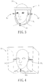
- FIG. 3 is a schematic diagram illustrating an embodiment of a positioning frame of the system according to the disclosure.
- FIG. 4 is a schematic diagram illustrating an embodiment of an augmented reality (AR) object including three virtual calibration rods according to the disclosure
- FIG. 5 is a schematic diagram illustrating an embodiment of a calibration tool of the system according to the disclosure.
- FIGS. 6 and 7 are schematic diagrams illustrating an embodiment of an ultrasound probe and the calibration tool of the system according to the disclosure
- FIG. 8 is a schematic diagram illustrating a second embodiment of the system for facilitating medical treatment according to the disclosure.
- FIG. 9 is a schematic diagram illustrating a third embodiment of the system for facilitating medical treatment according to the disclosure.
- FIG. 10 is a schematic diagram illustrating an embodiment of capturing an image by the system according to the disclosure.
- FIG. 11 is a schematic diagram of an embodiment of the image captured by the system.
- FIG. 12 is a schematic diagram of embodiments of treatment tools.
- FIG. 1 a first embodiment of a system for facilitating medical treatment is illustrated.
- the system is adapted to be utilized by an operator group 90 (only one member of the operator group is illustrated) to perform an operation on a subject 91 with assistance of a treatment tool 92 .
- the system includes an image capturing device 1 , a subject reference marker 2 , a tool reference marker 3 , at least one display device 4 , at least one operator reference marker 41 , and a processor 5 .
- the image capturing device 1 includes two image capturing modules 11 that are configured to simultaneously and respectively capture two images of the operator group 90 , the subject 91 and the treatment tool 92 .
- Each of said two images contains at least one of the subject reference marker 2 , the tool reference marker 3 and said at least one operator reference marker 41 .
- each of the image capturing modules 11 may be implemented to be a camera or a video recorder, but implementation thereof is not limited to the disclosure herein and may vary in other embodiments.
- each of the subject reference marker 2 , the tool reference marker 3 and said at least one operator reference marker 41 is implemented to be a circle with a cross, like what is shown in FIG.
- implementations of the subject reference marker 2 , the tool reference marker 3 and said at least one operator reference marker 41 are not limited to the disclosure herein and may vary in other embodiments.
- each of the subject reference marker 2 , the tool reference marker 3 and said at least one operator reference marker 41 may be implemented to be recognizable by color detection, shape detection, or barcode scan (e.g., coded as a linear barcode or a matrix barcode).
- the subject reference marker 2 is disposed adjacent to the subject 91 .
- the subject 91 is a patient who lies on a chair to undergo surgery, and the subject reference marker 2 is disposed on the chair.
- the tool reference marker 3 is to be disposed on the treatment tool 92 that is used by one member of the operator group 90 for medical treatment. It should be noted that implementation of each of the number of the tool reference marker 3 and the number of the treatment tool 92 is not limited to one, and may be plural number in other embodiments.
- Said at least one display device 4 is configured to be mounted on member(s) of the operator group 90 .
- each of said at least one display device 4 is a head-mounted device including a see-through display 42 .
- Each of said at least one operator reference marker 41 is disposed on a distinct one of said at least one display device 4 .
- the number of said at least one display device 4 is assumed to be one as shown in FIGS. 1 and 8 . That is to say, a scenario of a single operator wearing the display device 4 is shown in FIGS. 1 and 7 .
- the number of said at least one display device 4 and the number of member(s) of the operator group 90 are not limited to the disclosure herein and may vary in other embodiments.
- the processor 5 is electrically connected to the image capturing device 1 , and is communicable with said at least one display device 4 by means of wireless communication.
- the processor 5 may be implemented by a Central Processing Unit (CPU) in a computer, a microprocessor or any circuit configurable or programmable in a software manner and/or hardware manner to implement functionalities discussed in this disclosure.
- CPU Central Processing Unit
- microprocessor any circuit configurable or programmable in a software manner and/or hardware manner to implement functionalities discussed in this disclosure.
- implementation of the processor 5 is not limited to the disclosure herein.
- the processor 5 is configured to receive the images, to perform a spatial analysis on the images so as to obtain spatial locations of the subject reference marker 2 , the tool reference marker 3 and said at least one operator reference marker 41 , and to transmit auxiliary information regarding the subject 91 and coordinate information regarding the spatial locations to said at least one display device 4 .
- implementation of performing the spatial analysis on the images is known to one skilled in the relevant art, so detailed explanation of the same is omitted herein for the sake of brevity, and only a conceptual explanation of the spatial analysis performed by the system according to the disclosure is described as follows, where said at least one operator reference marker 41 and said at least one display device 4 are both assumed to be plural in number.
- the processor 5 is configured to transmit the first vector matrix X 1 to each of the display devices 4 , where V t ⁇ V i represents a relative vector of the tool reference marker 3 on the treatment tool 92 with respect to the operator reference marker 41 on the i th one of the head-mounted displays 4 , V f ⁇ V t represents a relative vector of the subject reference marker 2 with respect to the tool reference marker 3 on the treatment tool 92 , V i ⁇ V f represents a relative vector of the operator reference marker 41 on the i th one of the head-mounted displays 4 with respect to the subject reference marker 2 , where i is an integer from one to N.
- the tip 93 of the treatment tool 92 is where the treatment tool 92 is to be utilized to contact the subject 91 , and a distance (Vt 1 ) between the tip 93 of the treatment tool 92 and the tool reference marker 3 is constant and predetermined.
- the processor 5 utilizes the predetermined second spatial transformation matrix T 2 to transform the second vector matrix X 2 , which carries the coordinate information regarding the spatial locations of the tool reference marker 3 with respect to the operator reference markers 41 that respectively serve as origins, into the third vector matrix X 3 , which carries coordinate information regarding the spatial locations of the tip 93 of the treatment tool 92 with respect to the same origins, respectively.
- T ⁇ ⁇ 1 [ a ⁇ ⁇ 1 a ⁇ ⁇ 2 a ⁇ ⁇ 3 0 b ⁇ ⁇ 1 b ⁇ ⁇ 2 b ⁇ ⁇ 3 0 c ⁇ ⁇ 1 c ⁇ ⁇ 2 c ⁇ ⁇ 3 0 0 0 0 1 ] * [ d ⁇ ⁇ 1 d ⁇ ⁇ 2 d ⁇ ⁇ 3 0 e ⁇ ⁇ 1 e ⁇ ⁇ 2 e ⁇ ⁇ 3 0 f ⁇ ⁇ 1 f ⁇ ⁇ 2 f ⁇ ⁇ 3 0 0 0 0 1 ] - 1 .
- the second spatial transformation matrix T 2 satisfies another mathematical relationship
- T ⁇ ⁇ 2 [ d ⁇ ⁇ 1 d ⁇ ⁇ 2 d ⁇ ⁇ 3 0 e ⁇ ⁇ 1 e ⁇ ⁇ 2 e ⁇ ⁇ 3 0 f ⁇ ⁇ 1 f ⁇ ⁇ 2 f ⁇ ⁇ 3 0 0 0 0 1 ] * [ g ⁇ ⁇ 1 g ⁇ ⁇ 2 g ⁇ ⁇ 3 0 h ⁇ ⁇ 1 h ⁇ ⁇ 2 h ⁇ ⁇ 3 0 i ⁇ ⁇ 1 i ⁇ ⁇ 2 i ⁇ ⁇ 3 0 0 0 0 0 1 ] - 1 .
- the auxiliary information contains an augmented reality (AR) object 94 related to treatment of the subject 91 .
- the see-through display 42 of each of said at least one display device 4 is configured to display the AR object 94 at a desired position with respect to one of the subject 91 and the treatment tool 92 based on the auxiliary information and the coordinate information regarding the spatial locations (e.g., the first vector matrix X 1 , the second vector matrix X 2 or the third vector matrix X 3 ) so that the AR object 94 is properly arranged with respect to the subject 91 in space.
- the spatial locations e.g., the first vector matrix X 1 , the second vector matrix X 2 or the third vector matrix X 3
- the auxiliary information to be displayed on the display device 4 of the system according to the disclosure is illustrated.
- a member of the operator group 90 hereinafter referred to as an operator who wears the display device 4 is capable of seeing the AR object 94 that is to be fit to a head of the subject 91 (i.e., the patient) in space as what is shown in FIG. 2 . Since the AR object 94 is displayed at the desired position where the operator is performing the medical treatment, medical information necessary for the medical treatment may be conveniently perceived. In this way, the operator is able to concentrate on performing the medical treatment and does not have to divert his/her attention elsewhere, thereby facilitating the process of the medical treatment.
- each display device 4 includes a processing module (not shown) that is configured to control the see-through display 42 to display the AR object 94 of the auxiliary information at the desired position with respect to the subject 91 based on the coordinate information regarding the spatial locations (e.g., the first vector matrix X 1 , the second vector matrix X 2 or the third vector matrix X 3 ) received from the processor 5 .
- a processing module not shown
- the display device 4 may be replaced by a conventional display such as a liquid-crystal display (LCD) or a light-emitting diode (LED) display that is configured to display the AR object 94 of the auxiliary information.
- a conventional display such as a liquid-crystal display (LCD) or a light-emitting diode (LED) display that is configured to display the AR object 94 of the auxiliary information.
- LCD liquid-crystal display
- LED light-emitting diode
- the first embodiment of the system according to the disclosure further includes a positioning frame 6 .
- the positioning frame 6 includes a frame body 61 that is configured to be worn on the head of the subject 91 .
- the positioning frame 6 further includes a first calibration rod 62 , a second calibration rod 63 and a third calibration rod 64 that are disposed on the frame body 61 .
- the first calibration rod 62 and the second calibration rod 63 are configured to be arranged along an imaginary axis so that, when the frame body 61 is worn on the head of the subject 91 , the first calibration rod 62 and the second calibration rod 63 respectively abut against two ears of the subject 91 .
- the third calibration rod 64 is configured to be arranged to abut against a lower jaw of the subject 91 .
- the AR object 94 includes a three-dimensional medical image associated with the head of the subject 91 .
- the AR object 94 further includes a virtual first calibration rod 941 , a virtual second calibration rod 942 and a virtual third calibration rod 943 respectively resembling the first calibration rod 62 , the second calibration rod 63 and the third calibration rod 64 . It is worth noting that dimensions of the virtual first calibration rod 941 , the virtual second calibration rod 942 and the virtual third calibration rod 943 should respectively match the first calibration rod 62 , the second calibration rod 63 and the third calibration rod 64 of the positioning frame 6 .
- the virtual first calibration rod 941 , the virtual second calibration rod 942 and the virtual third calibration rod 943 are respectively aligned with the first calibration rod 62 , the second calibration rod 63 and the third calibration rod 64 of the positioning frame 6 so that the three-dimensional medical image is displayed at a corresponding position of the head of the subject 91 .
- the head-mounted device 4 further includes an input unit (not shown) that is configured to be operated by the operator wearing the display device 4 to input data or commands.
- the input unit may be implemented by a touchpad, a button set, or a gesture controlled user interface, but implementation thereof is not limited to the disclosure herein and may vary in other embodiments.
- the alignment of the first and second calibration rods 62 and 63 of the positioning frame 6 with the virtual first and second calibration rods 941 and 942 is initially performed. After the alignment is completed, parameters associated with relative position between the imaging capturing device 1 , the display device 4 and the subject 91 are stored by the display device 4 , and the relative position of the operator wearing the display device 4 with respect to the subject 91 is expected not to change. Afterward, the alignment of the third calibration rod 64 of the positioning frame 6 with the virtual third calibration rod 943 is performed.
- the calibration procedure can be repeated until the alignment of the first, second and third calibration rods 62 to 64 of the positioning frame 6 with the virtual first, second and third calibration rods 941 to 943 is satisfactory.
- the parameters associated with the relative positions of the first, second and third calibration rods 62 to 64 of the positioning frame 6 and the virtual first, second and third calibration rods 941 to 943 are stored by the display device 4 or transmitted by the display device 4 to the processor 5 .
- the three-dimensional medical image of the AR object 94 includes one of a magnetic resonance imaging (MRI) image, a computed tomography (CT) image, a two-dimensional cross sectional medical ultrasound image, and a three-dimensional model reconstructed from medical ultrasound images.
- MRI magnetic resonance imaging
- CT computed tomography
- the three-dimensional medical image of the AR object 94 is not limited to the disclosure herein and may vary in other embodiments.
- the three-dimensional model may be reconstructed by the processor 5 or by another computing device based on multiple two-dimensional medical images regarding, e.g., skin, brain or bone of the subject 91 so as to provide information of a spatial structure of, e.g., the skin, brain or bone of the subject 91 . Since implementation of the generation of the three-dimensional model is well known in the art, detailed explanation of the same is omitted herein for the sake of brevity.
- the AR object 94 includes a plurality of virtual facial features resembling facial features (e.g., eyes or ears) of the subject 91 and a three-dimensional medical image associated with the head of the subject 91 .
- the virtual facial features of the AR object 94 are aligned with the facial features of the subject 91 so that the three-dimensional medical image is displayed at a corresponding position of the head of the subject 91 .
- the treatment tool 92 is implemented to be an ultrasonic probe 95
- the tip 93 of the treatment tool 92 is a focal point 951 of ultrasound energy emitted by the ultrasonic probe 95
- the system further includes a calibration tool 7 that is configured to be utilized in combination with the ultrasonic probe 95 .
- the calibration tool 7 includes an upper part 71 and a lower part 72 that has an end point 721 as shown in FIG. 5 .
- the lower part 72 of the calibration tool 7 is configured to be separable from the upper part 71 of the calibration tool 7 such that the upper part 71 remains combined with the ultrasonic probe 95 when the lower part 72 is separated from the upper part 71 as shown in FIG. 7 .
- the tool reference marker 3 is disposed on the upper part 71 of the calibration tool 7 .
- a distance (Vt 1 ) between the tool reference marker 3 and the end point 721 of the lower part 72 of calibration tool 7 is equal to a distance (Vt 1 ′) between the tool reference marker 3 and the focal point 951 after the calibration procedure has been executed by the system with respect to the ultrasonic probe 95 as shown in FIG. 7 .
- the second spatial transformation matrix T 2 is able to be determined by the processor 5 through performing spatial analysis on images of the tool reference marker 3 captured by the image capturing device 1 . Consequently, a corresponding position of the focal point 951 , which is invisible in real space, can be determined so as to enable the display device 4 to correctly display a virtual focal point through the see-through display 42 .
- system according to the disclosure may be implemented to perform the calibration procedure with respect to treatment tools which emit invisible energy for medical treatment, such as focused ultrasound treatment, microwave treatment, light amplification by the stimulated emission of radiation (LASER) treatment, electromagnetic stimulation, and radio-frequency (RF) electromagnetic treatment.
- treatment tools which emit invisible energy for medical treatment, such as focused ultrasound treatment, microwave treatment, light amplification by the stimulated emission of radiation (LASER) treatment, electromagnetic stimulation, and radio-frequency (RF) electromagnetic treatment.
- LASER stimulated emission of radiation
- RF radio-frequency
- the system is adapted to be utilized by an operator group 90 to perform an operation on a subject 91 with assistance of a treatment tool 92 .
- the system includes an image capturing device 1 , a first inertial sensor 82 that is disposed on the image capturing device 1 , a tool reference marker 3 that is disposed on the treatment tool 92 , a second inertial sensor 83 that is disposed on the tool reference marker 3 , a display device 4 , and a processor 5 that is electrically connected to the image capturing device 1 , the first inertial sensor 82 , the second inertial sensor 83 and the display device 4 .
- the image capturing device 1 along with the first inertial sensor 82 , is disposed on the display device 4 .
- the image capturing device 1 is configured to capture an image of the treatment tool 92 . It should be noted that the image capturing device 1 merely includes one image capturing module which may be implemented by a camera or a video recorder.
- the first inertial sensor 82 is configured to make inertial measurement of the image capturing device 1 and to generate a first orientation vector ⁇ t based on a result of the inertial measurement of the image capturing device 1 .
- the second inertial sensor 83 is configured to make inertial measurement of the tool reference marker 3 and to generate a second orientation vector ⁇ r based on a result of the inertial measurement of the tool reference marker 3 .
- Each of the first inertial sensor 82 and the second inertial sensor 83 may be implemented to be a three-axis accelerometer, a six-axis accelerometer, or any circuit configurable/programmable in a software manner and/or hardware manner to implement functionalities of an accelerometer or a magnetometer.
- each of the first orientation vector ⁇ t and the second orientation vector ⁇ r is implemented to be an Euler angle, but implementation thereof is not limited to the disclosure herein and may vary in other embodiments.
- the tool reference marker 3 is implemented to be a colored circle or a colored rectangle so that a shape of the tool reference marker 3 in images thereof captured by the image capturing device 1 can be easily recognized by the processor 5 .
- implementation of the tool reference marker 3 is not limited to the disclosure herein and may vary in other embodiments.
- the processor 5 is configured to receive the image, the first orientation vector ⁇ t and the second orientation vector ⁇ r , and to calculate coordinates defining a spatial location of the tool reference marker 3 with respect to the image capturing device 1 based on the first orientation vector ⁇ t , the second orientation vector ⁇ r , an area A′ of the tool reference marker 3 in the image, a position of the tool reference marker 3 in the image, and an actual distance R between the image capturing device land the tool reference marker 3 (see FIGS. 10 and 11 ).
- the processor 5 is electrically connected to and communicable with the image capturing device 1 by means of wireless communication.
- the processor 5 may be implemented by a Central Processing Unit (CPU) in a computer, a microprocessor or any circuit configurable or programmable in a software manner and/or hardware manner to implement functionalities mentioned in this disclosure.
- CPU Central Processing Unit
- microprocessor any circuit configurable or programmable in a software manner and/or hardware manner to implement functionalities mentioned in this disclosure.
- implementation of the processor 5 is not limited to the disclosure herein.
- FIG. 10 illustrates that the image capturing device 1 (see FIG. 8 ) is capturing an image of the tool reference marker 3 , where the tool reference marker 3 is positioned on an imaginary curved plane which represents a plane of focus (POF) of the image capturing device 1 .
- FIG. 11 is a schematic diagram illustrating the image of the tool reference marker 3 captured by the image capturing device 1 .
- the processor 5 performs the following steps S 1 to S 8 to obtain coordinates (x,y,z) defining the spatial location of the tool reference marker 3 with respect to the image capturing device 1 .
- step S 1 the processor 5 calculates the area A′ of the tool reference marker 3 in the image as shown in FIG. 11 by pixel-counting.
- step S 2 the processor 5 receives the first orientation vector ⁇ t and the second orientation vector ⁇ r respectively from the first inertial sensor 82 and the second inertial sensor 83 .
- the first orientation vector ⁇ t represents an Euler angle of the image capturing device 1
- the second orientation vector ⁇ r represents an Euler angle of the second inertial sensor 83 .
- step S 3 the image capturing device 1 and the tool reference marker 3 are arranged in advance, i.e., the display device 4 and the treatment tool 92 are arranged in advance, such that the first orientation vector ⁇ t outputted by the first inertial sensor 82 disposed on the image capturing device 1 is equal to the second orientation vector ⁇ r outputted by the second inertial sensor 83 disposed on the tool reference marker 3 .
- the first orientation vector ⁇ t and the second orientation vector ⁇ r may not be adjusted in advance to be equal to each other, but may be adjusted later based on a predetermined mathematical relationship (i.e., the relative positions of the display device 4 and the treatment tool 92 are fixed).
- step S 5 based on the first orientation vector ⁇ t , the second orientation vector ⁇ r , the area A′ of the tool reference marker 3 in the image, and the position of the tool reference marker 3 in the image, the processor 5 calculates the actual distance R between the tool reference marker 3 and the image capturing device 1 as shown in FIGS. 8 and 10 by means of geometric relationships. It should be noted that the actual distance R between the tool reference marker 3 and the image capturing device 1 is substantially equal to a distance between the first inertia sensor 82 and the second inertia sensor 83 . In this embodiment, the processor 5 calculates the actual distance R between the tool reference marker 3 and the image capturing device 1 according to a mathematical relationship:
- R cal R cal - R A cal A cal - A , where R cal is a predetermined distance, A cal is an area of the tool reference marker 3 calculated when the tool reference marker 3 is spaced apart from the image capturing device 1 by the predetermined distance R cal , A is the estimated actual area of the tool reference marker 3 calculated by the processor 5 in step S 4 based on the first orientation vector ⁇ t , the second orientation vector ⁇ r , and the area A′ of the tool reference marker 3 in the image.
- step S 6 referring to FIGS. 10 and 11 , based on the position of the tool reference marker 3 in the image, the processor 5 calculates an actual distance L between the tool reference marker 3 and an optical axis of the image capturing device 1 . Specifically speaking, the processor 5 determines the position of the tool reference marker 3 in the image represented as (L′, ⁇ ), where ⁇ is an angle formed by a vertical axis passing through a center of the image and an imaginary line connecting the center of the image and the tool reference marker 3 , and L′ is a length of the imaginary line connecting the center of the image and the tool reference marker 3 in the image.
- the processor 5 calculates the actual distance L between the tool reference marker 3 and an optical axis of the image capturing device 1 based on the length L′ and a ratio between the area A′ of the tool reference marker 3 in the image and the estimated actual area A of the tool reference marker 3 .
- step S 7 based on the actual distance R between the tool reference marker 3 and the image capturing device 1 and the actual distance L between the tool reference marker 3 and the optical axis of the image capturing device 1 , the processor 5 calculates an angle of the tool reference marker 3 with respect to the optical axis of the image capturing device 1 as shown in FIG. 10 by a mathematical relationship:
- step S 8 the processor 5 further calculates the coordinates (x,y,z) defining the spatial location of the tool reference marker 3 with respect to the image capturing device 1 according to:
- a third embodiment of the system for facilitating medical treatment is illustrated.
- the third embodiment is similar to the second embodiment, but is different from the second embodiment in aspects described as follows.
- the image capturing device 1 and the first inertia sensor 82 disposed thereon are not disposed on the display device 4 worn by the operator, but instead are positioned near the subject 91 (i.e., the patient).
- the processor 5 calculates the coordinates (x,y,z) defining the spatial location of the tool reference marker 3 , which may represent the spatial location of the second inertia sensor 83 as well, with respect to the image capturing device 1 as an origin.
- the processor 5 controls the see-through display 42 of the display device 4 (see FIG. 1 ) or a conventional computer display (not shown) to display the auxiliary information at the desired position based on the coordinates (x,y,z) thus calculated.
- the coordinates (x,y,z) defining the spatial location of the tool reference marker 3 correspond to the second vector matrix X 2 calculated in the first embodiment of the system according to the disclosure. Therefore, coordinate information regarding a spatial location of a tip 93 of the treatment tool 92 in the second or third embodiment of the system may be calculated similarly to the way of calculating the third vector matrix X 3 described in the first embodiment of the disclosure. Additionally, the way of calculating the coordinates (x,y,z) defining the spatial location of the tool reference marker 3 in the second and third embodiments may be utilized in the first embodiment of the system to calculate the second vector matrix X 2 .
- FIG. 12 there are two treatment tools 92 , one of which is implemented to be a surgical instrument ( 92 A), and the other one of which is implemented to be a handheld tool ( 92 B) for diagnosis by means of ultrasound.
- Two tool reference markers ( 3 A) and ( 3 B) are respectively disposed on the surgical instrument ( 92 A) and the handheld tool ( 92 B), and two second inertia sensors ( 83 A) and ( 83 B) are respectively disposed on the surgical instrument ( 92 A) and the handheld tool ( 92 B) as well.
- Ultrasound energy emitted by the handheld tool ( 92 B) defines a treatment field 921 that is a spatial region in which the emitted ultrasound energy is effective for treatment.
- the system of this disclosure is capable of tracking spatial positions of the treatment field 921 and a tip 93 of the surgical instrument ( 92 A) based on results of measurement by the second inertia sensors ( 83 A) and ( 83 B) and based on calculations of the first vector matrix X 1 , the second vector matrix X 2 and the third vector matrix X 3 .
- the processor 5 (see FIG. 1 ) is configured to enable the display device 4 (see FIG. 1 ) to correctly display virtual images of the treatment field 921 with respect to the tip 93 of the surgical instrument ( 92 A) through the see-through display 42 (see FIG. 1 ).
- the system for facilitating medical treatment captures images of the reference markers on the operator, the subject and the treatment tool, and analyzes the images to obtain spatial locations of the reference markers. Thereafter, the system provides the auxiliary information regarding the subject based on the coordinate information regarding the spatial locations, so as to facilitate performance of medical treatment with the treatment tool by the operator wearing the display device.
- the system enables the operator to see the subject and the AR object regarding the subject at the same time.
- medical images regarding the subject can be displayed at the desired position with respect to the subject because of the coordinate information thus calculated.
- important information in the medical images can be displayed through the see-through display by means of AR so as to assist the operator in operating the treatment tool for performing the medical treatment on the subject and making medical decision in time.
Landscapes
- Health & Medical Sciences (AREA)
- Engineering & Computer Science (AREA)
- Surgery (AREA)
- Life Sciences & Earth Sciences (AREA)
- Public Health (AREA)
- Nuclear Medicine, Radiotherapy & Molecular Imaging (AREA)
- General Health & Medical Sciences (AREA)
- Medical Informatics (AREA)
- Biomedical Technology (AREA)
- Veterinary Medicine (AREA)
- Animal Behavior & Ethology (AREA)
- Heart & Thoracic Surgery (AREA)
- Molecular Biology (AREA)
- Radiology & Medical Imaging (AREA)
- Primary Health Care (AREA)
- Epidemiology (AREA)
- Pathology (AREA)
- Theoretical Computer Science (AREA)
- General Physics & Mathematics (AREA)
- Physics & Mathematics (AREA)
- Oral & Maxillofacial Surgery (AREA)
- Computer Vision & Pattern Recognition (AREA)
- Gynecology & Obstetrics (AREA)
- Robotics (AREA)
- General Business, Economics & Management (AREA)
- General Engineering & Computer Science (AREA)
- Software Systems (AREA)
- Computer Hardware Design (AREA)
- Computer Graphics (AREA)
- Business, Economics & Management (AREA)
- Dentistry (AREA)
- Mechanical Engineering (AREA)
- Orthopedic Medicine & Surgery (AREA)
- Vascular Medicine (AREA)
- Data Mining & Analysis (AREA)
- Urology & Nephrology (AREA)
- Databases & Information Systems (AREA)
- Neurosurgery (AREA)
- Image Processing (AREA)
- Apparatus For Radiation Diagnosis (AREA)
Abstract
Description
X1=(V t −V 1 ,V t −V 2 , . . . ,V t −V N ,V f −V t ,V 1 −V f ,V 2 −V f , . . . ,V N −V f)
that serves as the coordinate information, in which the spatial location of the
X2=T1*X1
that serves as the coordinate information, in which the spatial locations of the
X3=T2*X3
that serves as the coordinate information, in which the spatial locations of the
the second vector matrix
and the third vector matrix
the first spatial transformation matrix T1 satisfies a mathematical relationship
and can be expressed as
Similarly, the second spatial transformation matrix T2 satisfies another mathematical relationship
and can be expressed as
where Rcal is a predetermined distance, Acal is an area of the
and ϕ is the angle formed by the vertical axis passing through the center of the image and the imaginary line connecting the center of the image and the
Claims (12)
X1=(V t −V 1 ,V t −V 2 , . . ., V t −V N ,V f −V t ,V 1 −V f ,V 2 −V f , . . .,V N −V f)
X2=T1*(V t −V 1 ,V t −V 2 , . . .,V t −V N ,V f −V t ,V 1 −V f V 2 −V f , . . .,V N −V f)
X3=T2*T1*(V t −V 1 ,V t −V 2 , . . .,V 1 −V N ,V f −V t ,V 1 −V f ,V 2 −V f , . . .,V N −V f)
Applications Claiming Priority (3)
| Application Number | Priority Date | Filing Date | Title |
|---|---|---|---|
| TW107114633A | 2018-04-30 | ||
| TW107114633A TWI678181B (en) | 2018-04-30 | 2018-04-30 | Surgical guidance system |
| TW107114633 | 2018-04-30 |
Publications (2)
| Publication Number | Publication Date |
|---|---|
| US20190328462A1 US20190328462A1 (en) | 2019-10-31 |
| US10820945B2 true US10820945B2 (en) | 2020-11-03 |
Family
ID=68291834
Family Applications (1)
| Application Number | Title | Priority Date | Filing Date |
|---|---|---|---|
| US16/179,020 Active 2039-03-28 US10820945B2 (en) | 2018-04-30 | 2018-11-02 | System for facilitating medical treatment |
Country Status (3)
| Country | Link |
|---|---|
| US (1) | US10820945B2 (en) |
| CN (1) | CN110403699B (en) |
| TW (1) | TWI678181B (en) |
Families Citing this family (14)
| Publication number | Priority date | Publication date | Assignee | Title |
|---|---|---|---|---|
| US11287874B2 (en) | 2018-11-17 | 2022-03-29 | Novarad Corporation | Using optical codes with augmented reality displays |
| US11857378B1 (en) * | 2019-02-14 | 2024-01-02 | Onpoint Medical, Inc. | Systems for adjusting and tracking head mounted displays during surgery including with surgical helmets |
| US11497924B2 (en) * | 2019-08-08 | 2022-11-15 | Realize MedTech LLC | Systems and methods for enabling point of care magnetic stimulation therapy |
| US11237627B2 (en) | 2020-01-16 | 2022-02-01 | Novarad Corporation | Alignment of medical images in augmented reality displays |
| US11950968B2 (en) | 2020-03-13 | 2024-04-09 | Trumpf Medizin Systeme Gmbh + Co. Kg | Surgical augmented reality |
| KR102637479B1 (en) * | 2020-11-18 | 2024-02-16 | 주식회사 뉴로소나 | low intensity focused ultrasound treatment apparatus |
| US12016633B2 (en) * | 2020-12-30 | 2024-06-25 | Novarad Corporation | Alignment of medical images in augmented reality displays |
| CN113509263B (en) * | 2021-04-01 | 2024-06-14 | 上海复拓知达医疗科技有限公司 | Object space calibration positioning method |
| CN113509264B (en) * | 2021-04-01 | 2024-07-12 | 上海复拓知达医疗科技有限公司 | Augmented reality system, method and computer readable storage medium based on correcting position of object in space |
| TWI785645B (en) * | 2021-06-11 | 2022-12-01 | 承鋆生醫股份有限公司 | Augmented Reality Based Surgical Assistance Method |
| US11948265B2 (en) | 2021-11-27 | 2024-04-02 | Novarad Corporation | Image data set alignment for an AR headset using anatomic structures and data fitting |
| WO2023152639A1 (en) * | 2022-02-08 | 2023-08-17 | Insightec, Ltd. | Conformal phased-array transducer arrangement |
| CN115005864B (en) * | 2022-05-16 | 2024-08-20 | 天津大学 | Ultrasonic probe calibration method based on electromagnetic positioning |
| CN116077182B (en) * | 2022-12-23 | 2024-05-28 | 北京纳通医用机器人科技有限公司 | Medical surgical robot control method, device, equipment and medium |
Citations (11)
| Publication number | Priority date | Publication date | Assignee | Title |
|---|---|---|---|---|
| US20130267838A1 (en) * | 2012-04-09 | 2013-10-10 | Board Of Regents, The University Of Texas System | Augmented Reality System for Use in Medical Procedures |
| US20130331686A1 (en) * | 2010-09-21 | 2013-12-12 | Medizinische Universitaet Innsbruck | Registration device, system, kit and method for a patient registration |
| US20140275760A1 (en) * | 2013-03-13 | 2014-09-18 | Samsung Electronics Co., Ltd. | Augmented reality image display system and surgical robot system comprising the same |
| US20160191887A1 (en) * | 2014-12-30 | 2016-06-30 | Carlos Quiles Casas | Image-guided surgery with surface reconstruction and augmented reality visualization |
| US20160249989A1 (en) * | 2015-03-01 | 2016-09-01 | ARIS MD, Inc. | Reality-augmented morphological procedure |
| US20170050050A1 (en) * | 2014-02-14 | 2017-02-23 | Brainlab Ag | Frameless Pre-Positioning for Radiosurgery |
| US20170056115A1 (en) * | 2015-08-27 | 2017-03-02 | Medtronic, Inc. | Systems, apparatus, methods and computer-readable storage media facilitating surgical procedures utilizing augmented reality |
| US20170318235A1 (en) * | 2014-10-07 | 2017-11-02 | Elbit Systems Ltd. | Head-mounted displaying of magnified images locked on an object of interest |
| US20180140362A1 (en) * | 2015-04-07 | 2018-05-24 | King Abdullah University Of Science And Technology | Method, apparatus, and system for utilizing augmented reality to improve surgery |
| US20190311542A1 (en) * | 2018-04-10 | 2019-10-10 | Robert E. Douglas | Smart operating room equipped with smart surgical devices |
| US20190380798A1 (en) * | 2017-03-07 | 2019-12-19 | Intuitive Surgical Operations, Inc. | Systems and methods for controlling tool with articulatable distal portion |
Family Cites Families (11)
| Publication number | Priority date | Publication date | Assignee | Title |
|---|---|---|---|---|
| JP4409004B2 (en) * | 1999-09-27 | 2010-02-03 | オリンパス株式会社 | Surgical calibration system |
| US7555331B2 (en) * | 2004-08-26 | 2009-06-30 | Stereotaxis, Inc. | Method for surgical navigation utilizing scale-invariant registration between a navigation system and a localization system |
| CN101404039B (en) * | 2008-03-28 | 2010-06-16 | 华南师范大学 | Virtual operation method and its apparatus |
| CN201542744U (en) * | 2009-10-27 | 2010-08-11 | 南京麦迪柯科技有限公司 | Stereotactic device |
| US9008757B2 (en) * | 2012-09-26 | 2015-04-14 | Stryker Corporation | Navigation system including optical and non-optical sensors |
| WO2015008470A2 (en) * | 2013-07-16 | 2015-01-22 | Seiko Epson Corporation | Information processing apparatus, information processing method, and information processing system |
| US10013808B2 (en) * | 2015-02-03 | 2018-07-03 | Globus Medical, Inc. | Surgeon head-mounted display apparatuses |
| US10195076B2 (en) * | 2015-10-23 | 2019-02-05 | Eye Labs, LLC | Head-mounted device providing diagnosis and treatment and multisensory experience |
| EP3426179B1 (en) * | 2016-03-12 | 2023-03-22 | Philipp K. Lang | Devices for surgery |
| KR101687821B1 (en) * | 2016-09-22 | 2016-12-20 | 장원석 | Method for dental surgery using augmented reality |
| US11839433B2 (en) * | 2016-09-22 | 2023-12-12 | Medtronic Navigation, Inc. | System for guided procedures |
-
2018
- 2018-04-30 TW TW107114633A patent/TWI678181B/en active
- 2018-11-02 US US16/179,020 patent/US10820945B2/en active Active
- 2018-11-09 CN CN201811329715.6A patent/CN110403699B/en active Active
Patent Citations (11)
| Publication number | Priority date | Publication date | Assignee | Title |
|---|---|---|---|---|
| US20130331686A1 (en) * | 2010-09-21 | 2013-12-12 | Medizinische Universitaet Innsbruck | Registration device, system, kit and method for a patient registration |
| US20130267838A1 (en) * | 2012-04-09 | 2013-10-10 | Board Of Regents, The University Of Texas System | Augmented Reality System for Use in Medical Procedures |
| US20140275760A1 (en) * | 2013-03-13 | 2014-09-18 | Samsung Electronics Co., Ltd. | Augmented reality image display system and surgical robot system comprising the same |
| US20170050050A1 (en) * | 2014-02-14 | 2017-02-23 | Brainlab Ag | Frameless Pre-Positioning for Radiosurgery |
| US20170318235A1 (en) * | 2014-10-07 | 2017-11-02 | Elbit Systems Ltd. | Head-mounted displaying of magnified images locked on an object of interest |
| US20160191887A1 (en) * | 2014-12-30 | 2016-06-30 | Carlos Quiles Casas | Image-guided surgery with surface reconstruction and augmented reality visualization |
| US20160249989A1 (en) * | 2015-03-01 | 2016-09-01 | ARIS MD, Inc. | Reality-augmented morphological procedure |
| US20180140362A1 (en) * | 2015-04-07 | 2018-05-24 | King Abdullah University Of Science And Technology | Method, apparatus, and system for utilizing augmented reality to improve surgery |
| US20170056115A1 (en) * | 2015-08-27 | 2017-03-02 | Medtronic, Inc. | Systems, apparatus, methods and computer-readable storage media facilitating surgical procedures utilizing augmented reality |
| US20190380798A1 (en) * | 2017-03-07 | 2019-12-19 | Intuitive Surgical Operations, Inc. | Systems and methods for controlling tool with articulatable distal portion |
| US20190311542A1 (en) * | 2018-04-10 | 2019-10-10 | Robert E. Douglas | Smart operating room equipped with smart surgical devices |
Non-Patent Citations (1)
| Title |
|---|
| Google Scholar Search Results. * |
Also Published As
| Publication number | Publication date |
|---|---|
| TW201944954A (en) | 2019-12-01 |
| CN110403699A (en) | 2019-11-05 |
| CN110403699B (en) | 2020-10-30 |
| TWI678181B (en) | 2019-12-01 |
| US20190328462A1 (en) | 2019-10-31 |
Similar Documents
| Publication | Publication Date | Title |
|---|---|---|
| US10820945B2 (en) | System for facilitating medical treatment | |
| US11100636B2 (en) | Systems, devices, and methods for tracking and compensating for patient motion during a medical imaging scan | |
| US20200022654A1 (en) | Systems, devices, and methods for tracking and compensating for patient motion during a medical imaging scan | |
| JP7478106B2 (en) | Extended reality visualization of optical instrument tracking volumes for computer-assisted navigation in surgery | |
| US9717461B2 (en) | Systems, devices, and methods for tracking and compensating for patient motion during a medical imaging scan | |
| EP2948056B1 (en) | System and method for tracking and compensating for patient motion during a medical imaging scan | |
| EP3858281A1 (en) | Pose measurement chaining for extended reality surgical navigation in visible and near infrared spectrums | |
| US12048502B2 (en) | Surgery robot system and use method therefor | |
| US8251893B2 (en) | Device for displaying assistance information for surgical operation, method for displaying assistance information for surgical operation, and program for displaying assistance information for surgical operation | |
| US20170296292A1 (en) | Systems and Methods for Surgical Imaging | |
| US8879801B2 (en) | Image-based head position tracking method and system | |
| US9256947B2 (en) | Automatic positioning of imaging plane in ultrasonic imaging | |
| US20210186355A1 (en) | Model registration system and method | |
| WO2014120909A1 (en) | Apparatus, system and method for surgical navigation | |
| US10675479B2 (en) | Operation teaching device and transcranial magnetic stimulation device | |
| EP3922203A1 (en) | Surgical object tracking in visible light via fiducial seeding and synthetic image registration | |
| CN113197666A (en) | Device and system for surgical navigation | |
| US20220409314A1 (en) | Medical robotic systems, operation methods and applications of same | |
| JP2011050583A (en) | Medical diagnostic apparatus | |
| KR102443956B1 (en) | eXtended reality-based acupuncture system and method thereof | |
| KR102460821B1 (en) | Augmented reality apparatus and method for operating augmented reality apparatus | |
| WO2024164075A1 (en) | Three-dimensional imaging and machine learning system for identifying bony landmarks used in developing treatment protocols | |
| WO2020133097A1 (en) | Mixed-reality-based control system | |
| CN116981419A (en) | Method and system for non-contact patient registration in image-guided surgery | |
| CN116982079A (en) | Method and system for non-contact patient registration in image-guided surgery |
Legal Events
| Date | Code | Title | Description |
|---|---|---|---|
| FEPP | Fee payment procedure |
Free format text: ENTITY STATUS SET TO UNDISCOUNTED (ORIGINAL EVENT CODE: BIG.); ENTITY STATUS OF PATENT OWNER: LARGE ENTITY |
|
| AS | Assignment |
Owner name: CHANG GUNG UNIVERSITY, TAIWAN Free format text: ASSIGNMENT OF ASSIGNORS INTEREST;ASSIGNORS:LIU, HAO-LI;CHIOU, SHIN-YAN;LIAO, CHEN-YUAN;AND OTHERS;SIGNING DATES FROM 20181002 TO 20181003;REEL/FRAME:047485/0518 |
|
| AS | Assignment |
Owner name: CHANG GUNG UNIVERSITY, TAIWAN Free format text: ASSIGNMENT OF ASSIGNORS INTEREST;ASSIGNOR:CHANG GUNG UNIVERSITY;REEL/FRAME:048993/0055 Effective date: 20190403 Owner name: CHANG GUNG MEMORIAL HOSPITAL, LINKOU, TAIWAN Free format text: ASSIGNMENT OF ASSIGNORS INTEREST;ASSIGNOR:CHANG GUNG UNIVERSITY;REEL/FRAME:048993/0055 Effective date: 20190403 |
|
| STPP | Information on status: patent application and granting procedure in general |
Free format text: PUBLICATIONS -- ISSUE FEE PAYMENT VERIFIED |
|
| STCF | Information on status: patent grant |
Free format text: PATENTED CASE |
|
| AS | Assignment |
Owner name: UNI PHARMA CO., LTD., TAIWAN Free format text: ASSIGNMENT OF ASSIGNORS INTEREST;ASSIGNORS:CHANG GUNG UNIVERSITY;CHANG GUNG MEMORIAL HOSPITAL, LINKOU;SIGNING DATES FROM 20210805 TO 20210809;REEL/FRAME:058314/0800 |
|
| MAFP | Maintenance fee payment |
Free format text: PAYMENT OF MAINTENANCE FEE, 4TH YEAR, LARGE ENTITY (ORIGINAL EVENT CODE: M1551); ENTITY STATUS OF PATENT OWNER: LARGE ENTITY Year of fee payment: 4 |