US10820875B2 - X-ray system with computer implemented methods for image processing - Google Patents
X-ray system with computer implemented methods for image processing Download PDFInfo
- Publication number
- US10820875B2 US10820875B2 US15/757,985 US201615757985A US10820875B2 US 10820875 B2 US10820875 B2 US 10820875B2 US 201615757985 A US201615757985 A US 201615757985A US 10820875 B2 US10820875 B2 US 10820875B2
- Authority
- US
- United States
- Prior art keywords
- image
- gray level
- ray
- filter
- function
- Prior art date
- Legal status (The legal status is an assumption and is not a legal conclusion. Google has not performed a legal analysis and makes no representation as to the accuracy of the status listed.)
- Expired - Fee Related, expires
Links
- 238000000034 method Methods 0.000 title claims abstract description 41
- 238000012545 processing Methods 0.000 title claims abstract description 41
- 230000009466 transformation Effects 0.000 claims description 136
- 230000008859 change Effects 0.000 claims description 19
- 238000012886 linear function Methods 0.000 claims description 13
- 238000001514 detection method Methods 0.000 claims description 8
- 238000000844 transformation Methods 0.000 claims description 8
- 230000004048 modification Effects 0.000 claims description 5
- 238000012986 modification Methods 0.000 claims description 4
- 229920006395 saturated elastomer Polymers 0.000 abstract description 3
- 230000005855 radiation Effects 0.000 description 56
- 238000013459 approach Methods 0.000 description 14
- 238000003384 imaging method Methods 0.000 description 13
- 238000001914 filtration Methods 0.000 description 11
- 230000008569 process Effects 0.000 description 7
- 238000012937 correction Methods 0.000 description 6
- 238000009826 distribution Methods 0.000 description 6
- 238000005516 engineering process Methods 0.000 description 6
- 238000004364 calculation method Methods 0.000 description 5
- 230000005540 biological transmission Effects 0.000 description 4
- 238000002594 fluoroscopy Methods 0.000 description 4
- 239000000463 material Substances 0.000 description 4
- 238000005282 brightening Methods 0.000 description 3
- 238000002591 computed tomography Methods 0.000 description 3
- 206010016256 fatigue Diseases 0.000 description 3
- 238000004519 manufacturing process Methods 0.000 description 3
- 238000005457 optimization Methods 0.000 description 3
- 230000009467 reduction Effects 0.000 description 3
- XAGFODPZIPBFFR-UHFFFAOYSA-N aluminium Chemical compound [Al] XAGFODPZIPBFFR-UHFFFAOYSA-N 0.000 description 2
- 229910052782 aluminium Inorganic materials 0.000 description 2
- 238000004458 analytical method Methods 0.000 description 2
- 210000003484 anatomy Anatomy 0.000 description 2
- 230000001419 dependent effect Effects 0.000 description 2
- 238000013461 design Methods 0.000 description 2
- 238000002059 diagnostic imaging Methods 0.000 description 2
- 230000000694 effects Effects 0.000 description 2
- 238000010191 image analysis Methods 0.000 description 2
- 238000013152 interventional procedure Methods 0.000 description 2
- 239000007787 solid Substances 0.000 description 2
- 238000001228 spectrum Methods 0.000 description 2
- 230000001131 transforming effect Effects 0.000 description 2
- 241001270131 Agaricus moelleri Species 0.000 description 1
- 238000012935 Averaging Methods 0.000 description 1
- RYGMFSIKBFXOCR-UHFFFAOYSA-N Copper Chemical compound [Cu] RYGMFSIKBFXOCR-UHFFFAOYSA-N 0.000 description 1
- 238000010521 absorption reaction Methods 0.000 description 1
- 239000000654 additive Substances 0.000 description 1
- 230000000996 additive effect Effects 0.000 description 1
- 229910021417 amorphous silicon Inorganic materials 0.000 description 1
- 230000008901 benefit Effects 0.000 description 1
- 230000000903 blocking effect Effects 0.000 description 1
- 229910052802 copper Inorganic materials 0.000 description 1
- 239000010949 copper Substances 0.000 description 1
- 238000002586 coronary angiography Methods 0.000 description 1
- 230000000593 degrading effect Effects 0.000 description 1
- 239000003814 drug Substances 0.000 description 1
- 229940079593 drug Drugs 0.000 description 1
- 235000020280 flat white Nutrition 0.000 description 1
- 238000003709 image segmentation Methods 0.000 description 1
- 230000002452 interceptive effect Effects 0.000 description 1
- 210000004072 lung Anatomy 0.000 description 1
- 238000005259 measurement Methods 0.000 description 1
- 230000003287 optical effect Effects 0.000 description 1
- 238000012805 post-processing Methods 0.000 description 1
- 238000007781 pre-processing Methods 0.000 description 1
- 238000003825 pressing Methods 0.000 description 1
- 238000004886 process control Methods 0.000 description 1
- 239000012857 radioactive material Substances 0.000 description 1
- 238000002601 radiography Methods 0.000 description 1
- 238000011160 research Methods 0.000 description 1
- 230000026954 response to X-ray Effects 0.000 description 1
- 230000009291 secondary effect Effects 0.000 description 1
- 230000003595 spectral effect Effects 0.000 description 1
- 238000003860 storage Methods 0.000 description 1
- 230000001225 therapeutic effect Effects 0.000 description 1
- 238000012546 transfer Methods 0.000 description 1
- 238000002834 transmittance Methods 0.000 description 1
- 238000004846 x-ray emission Methods 0.000 description 1
Images


Classifications
-
- A—HUMAN NECESSITIES
- A61—MEDICAL OR VETERINARY SCIENCE; HYGIENE
- A61B—DIAGNOSIS; SURGERY; IDENTIFICATION
- A61B6/00—Apparatus or devices for radiation diagnosis; Apparatus or devices for radiation diagnosis combined with radiation therapy equipment
- A61B6/52—Devices using data or image processing specially adapted for radiation diagnosis
- A61B6/5205—Devices using data or image processing specially adapted for radiation diagnosis involving processing of raw data to produce diagnostic data
-
- G—PHYSICS
- G06—COMPUTING; CALCULATING OR COUNTING
- G06T—IMAGE DATA PROCESSING OR GENERATION, IN GENERAL
- G06T5/00—Image enhancement or restoration
- G06T5/40—Image enhancement or restoration using histogram techniques
-
- A—HUMAN NECESSITIES
- A61—MEDICAL OR VETERINARY SCIENCE; HYGIENE
- A61B—DIAGNOSIS; SURGERY; IDENTIFICATION
- A61B6/00—Apparatus or devices for radiation diagnosis; Apparatus or devices for radiation diagnosis combined with radiation therapy equipment
- A61B6/06—Diaphragms
-
- A—HUMAN NECESSITIES
- A61—MEDICAL OR VETERINARY SCIENCE; HYGIENE
- A61B—DIAGNOSIS; SURGERY; IDENTIFICATION
- A61B6/00—Apparatus or devices for radiation diagnosis; Apparatus or devices for radiation diagnosis combined with radiation therapy equipment
- A61B6/54—Control of apparatus or devices for radiation diagnosis
- A61B6/542—Control of apparatus or devices for radiation diagnosis involving control of exposure
-
- G06T5/009—
-
- G—PHYSICS
- G06—COMPUTING; CALCULATING OR COUNTING
- G06T—IMAGE DATA PROCESSING OR GENERATION, IN GENERAL
- G06T5/00—Image enhancement or restoration
- G06T5/90—Dynamic range modification of images or parts thereof
- G06T5/92—Dynamic range modification of images or parts thereof based on global image properties
-
- G—PHYSICS
- G06—COMPUTING; CALCULATING OR COUNTING
- G06T—IMAGE DATA PROCESSING OR GENERATION, IN GENERAL
- G06T2207/00—Indexing scheme for image analysis or image enhancement
- G06T2207/10—Image acquisition modality
- G06T2207/10116—X-ray image
-
- G—PHYSICS
- G06—COMPUTING; CALCULATING OR COUNTING
- G06T—IMAGE DATA PROCESSING OR GENERATION, IN GENERAL
- G06T2207/00—Indexing scheme for image analysis or image enhancement
- G06T2207/20—Special algorithmic details
- G06T2207/20172—Image enhancement details
- G06T2207/20208—High dynamic range [HDR] image processing
Definitions
- the invention is related to the field of imaging systems and more particularly to the field of image processing in images of x-ray systems involving a filter based region of interest.
- Devices and system that generate various forms of radiation/ionizing energy are used for various therapeutic/treatment, diagnostic or imaging purposes.
- various forms of radiation/ionizing energy may be used to inspect an object (such as in airports scanning systems, different security setups, manufacturing and process control) or inspect a patient (such as in a clinic or a hospital, e.g. Cath lab, where a surgeon/therapist operates an X Ray or CT system.)
- the first component is the technical improvements of the x-ray equipment, such as investment in better filtering, collimators, acquisition equipment and image analysis.
- the other component is the way the operator uses the radiation, which includes the length of exposure, distance from the source to the patient and proper collimation. See Miller D L, Balter S, Schueler B A, Wagner L K, Strauss K J, Vano E. “Clinical radiation management for fluoroscopically guided interventional procedures”, Radiology .
- an x-ray system comprising an x-ray source, at least one partially transparent x-ray filter, an x-ray detector, a monitor to display x-ray images detected by said detector and image processing means, said system configured to generate at least one x-ray image and modify at least one of said at least one image for display by:
- At least one of said first and second gray level transformation functions may be a monotonic increasing function.
- At least one of said first and second gray level transformation functions may be selected from the group consisting of:
- At least one of said first and second gray level transformation functions may be a monotonic increasing function.
- the system may further be configured to determine said first gray level using a method selected from the group consisting of:
- the system may further be configured to execute at least one of the following for each frame:
- the system may further be configured to execute at most two of the following for each frame:
- the system may further be configured to execute at least one of the following, following a detection of a predetermined level of change in a sequence of images:
- the system may further be configured to calculate histograms of said images calculated as without filtering and following detection of a level of change in the images histograms brighter pixels, execute at least one of the following:
- the system may further be configured to execute at least one of the following based on at least one image with the largest dynamic range among multiple frames:
- the system may further be configured to execute at least one of the following based on at least one image with the largest dynamic range among a predetermined number of last frames:
- the system may further be configured to execute at least one of the following based on at least one image with the largest dynamic range among frames received in a predetermined time range:
- the system may further be configured to execute at least one of the following based on the average of at least two images with the largest dynamic range among multiple frames:
- the system may further be configured to execute at least one of the following based on the average of at least two images with the largest dynamic range among a predetermined number of last frames:
- the system may further be configured to execute at least one of the following based on the average of at least two images with the largest dynamic range among frames received in a predetermined time range:
- the system may further be configured to execute at least one of the following based on a weighted average of past images:
- the system may further be configured to execute at least one of the following based on a weighted average of past images:
- the system may further be configured to execute at least one of the following based on a subset of received frames:
- An operator may be configured to determine said at least one part of said image unfiltered by said at least one filter in real time.
- the system may further be configured to determine said at least one part of the image unfiltered by said at least one filter in real time automatically.
- the system may further be configured to determine said at least one part of the image unfiltered by said at least one filter using stored past history.
- an x-ray system comprising an x-ray source, at least one partially transparent x-ray filter, an x-ray detector, a monitor to display x-ray images detected by said detector and image processing means, said system configured to generate at least one x-ray image and modify at least one of said at least one image for display by:
- At least one of said first and second gray level transformation functions may be a monotonic increasing function.
- At least one of said first and second gray level transformation functions may be selected from the group consisting of:
- At least one of said first and second gray level transformation functions may be a monotonic increasing function.
- the system may further be configured to determine said first gray level using a method selected from the group consisting of:
- the system may further be configured to execute at least one of the following, following a detection of a level of change in a sequence of images:
- the system may further be configured to calculate histograms of said images calculated as without filtering and following detection of a level of change in the images histograms brighter pixels, execute at least one of the following:
- the system may further be configured to execute at least one of the following based on at least one image with the largest dynamic range among frames received in a predetermined time range:
- the system may further be configured to execute at least one of the following based on a weighted average of past images:
- the system may further be configured to execute at least one of the following based on a weighted average of past images:
- said system is further configured to reset said weighted average calculation when the latest image varies from said weighted average more than a threshold.
- an x-ray system comprising an x-ray source, at least one partially transparent x-ray filter, an x-ray detector, a monitor to display x-ray images detected by said detector and image processing means, said system configured to generate at least one x-ray image and modify at least one of said at least one image for display by:
- At least one of said at least one first and second gray level transformation functions may be a monotonic increasing function.
- At least one of said at least one first and second gray level transformation functions may be selected from the group consisting of:
- At least one of said at least one first and second gray level transformation functions may be a monotonic increasing function.
- the system may further be configured to determine said at least one of GL(ref), GL(maxB), GL(maxC) GL(refC), GL(pC), GL(pD) and GL(highD) using a method selected from the group consisting of:
- the system may further be configured to execute at least one of the following, following a detection of a level of change in a sequence of images:
- the system may further be configured to calculate histograms of said images calculated as without filtering and following detection of a level of change in said images histograms brighter pixels, execute at least one of the following:
- the system may further be configured to execute at least one of the following based on at least one image with the largest dynamic range among frames received in a predetermined time range:
- the system may further be configured to execute at least one of the following based on a weighted average of past images:
- the system may further be configured to execute at least one of the following based on a weighted average of past images:
- said system is further configured to reset said weighted average calculation when the latest image varies from said weighted average more than a threshold.
- an x-ray system comprising an x-ray source, at least one partially transparent x-ray filter, an x-ray detector, a monitor to display x-ray images detected by said detector and image processing means, wherein said display comprises a dynamic range;
- Said modification may be made by at least one gray level transformation function selected from the group consisting of:
- a first gray level may be determined based on said unfiltered image
- a second gray level may be determined based on said filtered image
- said at least one pixel of said filtered image may be transformed by a transformation so that said second gray level is changed relative to said first gray level
- said transformation may maintain the gray levels of said filtered image within said determined range of said dynamic range of said display.
- the difference between said first gray level and said second gray level after said transformation may be less than 25% of said determined range of said dynamic range of said display.
- an x-ray system comprising an x-ray source, at least one partially transparent x-ray filter, an x-ray detector, a monitor to display x-ray images detected by said detector and image processing means, wherein said display comprises a dynamic range;
- said system configured to generate at least one x-ray image and modify at least one of said at least one image for display by:
- Said modification may be made by at least one gray level transformation function selected from the group consisting of:
- a first gray level may be determined based on said unfiltered image
- a second gray level may be determined based on said filtered image
- said at least one pixel of said filtered image may be transformed by a transformation so that said second gray level is changed relative to said first gray level
- said transformations maintain the gray levels of said filtered and unfiltered images within their corresponding said determined ranges of said dynamic range of said display.
- the difference between said first gray level and said second gray level after said transformations may be less than 25% of said dynamic range of said display.
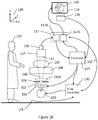
- FIG. 1A is a simplified schematic illustration of an example layout of a multiple frames imaging clinical environment and system
- FIG. 1B is an illustration of an example of a layout of the system of FIG. 1A showing additional details of components of the system example of the invention
- FIG. 2 is a schematic illustration of an example of image displayed on a monitor of a multiple frames imaging system
- FIG. 3 is a schematic illustration of additional aspects of the system example of FIG. 1A ;
- FIG. 4A provides a top view of the collimator according to the present invention.
- FIG. 4B is cross section c-c of the collimator of FIG. 4A ;
- FIG. 4C provides a schematic DPP graph as a function of distance from the center
- FIG. 4D provides a representation of a monitor with the displayed frame associated with the collimator of FIG. 4A ;
- FIG. 5 presents an exemplary system for carrying out the invention
- FIGS. 6 and 6.1 provide a top view of a collimator/filter constructed of an example of four x-ray partially transparent plates
- FIG. 6.2 represents the x-ray cone cross section at generally the plane of collimator of FIG. 6 ;
- FIG. 7 illustrates the x-ray intensity distribution in different areas of the image of the collimator/filter of FIG. 6 at an example position
- FIG. 8A shows an image or detector area represented as a rectangle with one image line
- FIG. 8B is an example of DPP distribution along the image line of FIG. 8A at the detector
- FIG. 8C represents a display system having 256 gray levels
- FIG. 8D shows the details of the image line compressed to a flat gray level 255
- FIG. 9A is an example of the image line of FIG. 8B where added dashed lines indicate the borders between 3 parts of the image;
- FIG. 9B shows the reduced DPP in the backgrounds and the unchanged DPP in the ROI
- FIG. 9C shows a corrected image of FIG. 9B so as to restore the image to what it would have been without filtering
- FIG. 9D shows the result as a washed out part of the image that has no image details
- FIG. 9E shows the result after applying a basic background processing
- FIG. 9F shows providing continuity of the image along the image line of FIG. 8B , at the location of the border lines;
- FIG. 9G shows a gray level gap along image line of FIG. 8B that can result from a specific choice of ROI_GL(max), BCK_GL(min) and transformation function;
- FIG. 9H shows gray level “overshoot” and gaps along the image line of FIG. 8B that can result from a specific choice of ROI_GL(max), BCK_GL(min) and transformation function;
- FIG. 9I illustrates a data in image part (ROI) that is dark
- FIG. 9J illustrates the data of FIG. 9I when the filter is used
- FIG. 9K illustrates the result of increased x-ray intensity relative to FIG. 9J .
- FIG. 9L illustrates image part 910 with improved S/N and image parts 912 and 914 transformed to provide the rest of the image details in a continuous manner of gray levels
- FIG. 10 is a flowchart showing the basic workflow of a system according to the present invention.
- FIGS. 11A-11D represent histograms of at least a part of the image.
- FIG. 1A presents a typical layout of a multiple frames imaging clinical environment, such as described in international patent application no. PCT/162013/051541, incorporated herein by reference.
- X-ray tube 100 generates x-ray radiation 102 directed upward and covering a relatively large solid angle towards collimator 104 .
- Collimator 104 blocks part of the radiation allowing a smaller solid angle of radiation to continue in the upward direction, go through bed 108 that is typically made of material that is relatively transparent to x-ray radiation and through patient 110 who is laying on bed 108 .
- Part of the radiation is absorbed and scattered by the patient and the remaining radiation arrives at the typically round input area 112 of image intensifier 114 .
- the input area of the image intensifier is typically in the order of 300 mm in diameter but may vary per the model and technology.
- the image generated by image intensifier 114 is captured by camera 116 , processed by image processor 117 and then displayed on monitor 118 as image 120 .
- x-ray source is used to provide a wide interpretation for a device having x-ray point source that does not necessarily have the shape of a tube.
- x-ray tube is used in the examples of the invention in convention with common terminology in the art, it is represented here that the examples of the invention are not limited to a narrow interpretation of x-ray tube and that any x-ray source can be used in these examples (for example even radioactive material configured to function as a point source).
- Operator 122 is standing by the patient to perform the medical procedure while watching image 120 .
- the operator has a foot-switch 124 .
- continuous x-ray radiation or relatively high frequency pulsed x-ray as explained below
- the intensity of x-ray radiation is typically optimized in a tradeoff of low intensity that is desired to reduce exposure to the patient and the operator and high intensity radiation that is desired to enable a high quality image 120 (high S/N). With low intensity x-ray radiation and thus low exposure of the image intensifier input area, the S/N of image 120 might be so low that image 120 becomes useless.
- Coordinate system 126 is a reference Cartesian coordinate system with Y axis pointing into the page and X-Y is a plane parallel to planes such as that of collimator 104 and image intensifier input plane 112 .
- ROIs Regions of Interest
- the operator can see a clear image in the one or more ROIs and get a good enough image for general orientation in the rest of the image area.
- S/N of one area when S/N of one area is compared to S/N of another area the S/N are compared for pixels that have the same object (such as patient and operators hands and tools) transmittance.
- an area A is described as having lower S/N than area B it is assumed that the transmission of x-ray by the object to both areas is uniform over the area and is the same.
- S/N in area B is compared to area A for an area B in which also only 1 ⁇ 2 of the radiation arriving at the object is transmitted through to the image intensifier.
- the S (signal) of area A is the average reading value of the area A (average over time or over the area if it includes enough pixels in the statistical sense).
- the S (signal) of area B is the average reading value of the area B (average over time or over the area if it includes enough pixels in the statistical sense).
- Poisson Noise This is not a limitation of the invention and, if desired, the mathematics presented in association to Gaussian statistics can be replaced by that of Poisson statistics (or other statistics) without degrading the scope of the invention.
- the noise values associated with each signal are represented by the standard deviation of the Poisson statistics for that signal, known in the art as Poisson Noise.
- DPP dose per pixel
- FIGS. 1B and 10 An example of a more detailed layout of a multiple frames imaging clinical environment according to the present invention is described in FIGS. 1B and 10 .
- Operator 122 presses foot switch 124 to activate x-ray (step 1240 ).
- Eye tracker 128 (such as EyeLink 1000 available from SR Research Ltd., Kanata, Ontario, Canada) or any alternative input device provides indication where one or more operators (or users) 122 are focusing their attention (step 1128 ).
- This information is typically provided relative to monitor 118 .
- This information, the at least one desired center of ROI may be provided for example in terms of (X,Z) coordinates, in the plane of monitor 118 , using coordinate system 126 .
- the plane of monitor 118 and therefore also image 120 are parallel to the (X,Z) plane of coordinate system 126 .
- Other coordinate systems are possible, including coordinate systems that are bundled to monitor 118 and rotate with monitor 118 when it is rotated relative to coordinate system 126 .
- controller 127 which is basically a computer, such as any PC computer. If the controller 127 determines that the operator's focus of attention is not fixed on the image 120 , the x-ray tube 100 is not activated (step 1100 ). Otherwise, in step 1105 , x-ray tube 100 is activated and x-ray radiation is emitted towards collimator 104 (and/or 150 / 150 A).
- Box 150 in FIG. 1B represents a collimator according to the present invention, as described in international patent application no. PCT/162014/065661 incorporated herein by reference.
- Box 150 can be located under collimator 104 , above collimator 104 as shown by numerical reference 150 A or instead of collimator 104 (not shown in FIG. 1B ).
- the collimators represented by boxes 150 and 150 A are controlled by controller 127 .
- X-ray emission is also controlled by controller 127 , typically through x-ray controller 130 .
- x-ray can be stopped even if operator 122 presses foot-switch 124 if at least one of the users' desired center of ROI is not within image 120 area.
- the collimator partially blocks radiation, depending on the determined at least one desired center of ROI (step 1220 ).
- step 1230 Part of the x-rays are absorbed by the patient 110 (step 1230 ) and the remaining radiation arrives at the image intensifier 114 (step 1240 ).
- step 1250 the image is intensified and captured by a camera 116 and in step 1260 the captured image is transferred to the image processor 117 and in step 1270 the processed image is displayed on monitor 120 .
- FIG. 2 illustrating an example of an image 120 displayed on monitor 118 .
- dashed circle line 204 indicates the border between segment 200 of the image and segment 202 of the image, both segments constitute the entire image 120 .
- it is desired to get a good image quality in segment 200 meaning higher x-ray DPP for segment 200 and it is acceptable to have a lower image quality in segment 202 , meaning lower DPP for segment 202 .
- the two segments 200 and 202 are provided here only as one example of an embodiment of the invention that is not limited to this example and that image 120 can be divided to any set of segments by controlling the shape of the apertures in the collimators and the mode of motion of the collimators. Such examples are provided below.
- DPP should be interpreted as the x-ray dose delivered towards a segment representing one pixel of image 120 to generate the pixel readout value used to construct image 120 (excluding absorption by the patient or other elements which are not a part of the system, such as the hands and tools of the operator).
- a typical collimator 104 having a round aperture 304 is introduced to the x-ray path so that only x-rays 106 that are projected from focal point 306 of x-ray tube 100 and pass through aperture 304 arrive at the round input surface 112 of image intensifier 114 while other x-rays 102 are blocked by the collimator.
- This arrangement exposes the entire input area 112 of the image intensifier to generally the same DPP.
- Such an arrangement does not provide the function of one DPP to segment 300 that correlates with segment 200 of FIG. 2 and another DPP to segment 302 that correlates with segment 202 of FIG. 2 .
- the diameter of input area 112 is B as indicated in FIG. 3 .
- D 1 represents the distance from the x-ray focal point 306 to aperture 304 .
- D 2 represents the distance from the x-ray focal point 306 to image intensifier input surface 112 .
- FIG. 4A provides a top view of another collimator 400 and FIG. 4B is cross section c-c of FIG. 4A .
- Collimator 400 provides a similar function of x-ray reduction as other collimators of the invention. It has an aperture 402 that allows all the radiation in that area to pass through, annulus 406 that reduces the radiation passing through the area at amount depending on the material (typically aluminum) and the thickness of the material and annulus 404 with thickness changing as a function of the distance from the center, starting at thickness zero on the side of aperture 402 ending at the thickness of annulus 406 on the side of annulus 406 .
- FIG. 4C provides a schematic DPP graph as a function of distance from the center: r.
- FIG. 4D provides a representation of monitor 118 with the displayed frame associated with collimator 400 .
- Circle 422 is the area associated with radiation arriving through aperture 402 of collimator 400 .
- Annulus 424 is the area associated with radiation arriving through annulus 404 of collimator 400 .
- Annulus 426 is the area associated with radiation arriving through annulus 406 of collimator 400 .
- FIG. 5 presents an exemplary system for carrying out the invention.
- an ROI is centered in image 120 (such as ROI 200 of FIG. 2 ) and has a fixed position which is used for image analysis and for generating parameters to drive x-ray tube 100 and modify image 120 .
- Parameters such as average value, maximum value and contrast may be calculated for this area.
- Such parameters are typically used to optimize the x-ray tube operation (such as mA, mAs and KVp).
- an input device such as an eye tracker 128 is used to provide x-ray controller 130 with the focus of attention coordinates of one or more users 122 .
- the one or more ROIs move according to the focus of attention so that they include the desired centers of the ROIs or are near the desired centers of the ROIs.
- the analysis and parameters calculated from the ROIs to drive the x-ray tube and modify image 120 are made from at least one ROI that is located according to the focus of attention instead of a fixed ROI, that may sometimes be at a distance from the focus of attention and not represent the image information that is relevant to the focus of attention.
- the input device can be any input device that affects the position and/or the shape of the ROI.
- an eye tracker, a joy-stick, a keyboard, an interactive display, a gesture reading device, a voice interpreter or any other suitable device can be used to determine coordinates relative to image 120 , and the ROI position and/or shape changes according to such input.
- Collimator 600 comprises four plates 601 , 602 , 603 and 604 that are opaque or partially transparent to x-ray. In this example we shall assume that each such plate transmits 10% of beam 106 but it would be appreciated that other transmission levels may be contemplated. Plates 601 , 602 , 603 and 604 can be made from any suitable material, considering the desired effect of the spectral distribution of the transmitted x-ray beam. For example, copper or aluminum plates can be used. Dashed circle 106 A represents x-ray cone 106 cross section at generally the plane of collimator 600 . Except for a rectangular shaped x-ray beam portion 612 , the rest of the beam intensity is reduced due to plates 601 , 602 , 603 and 604 .
- a circular image/circular cone shape x-ray beam is only an example.
- the x-ray beam and the image may be rectangular or any other shape, depending on the c-arm and collimator setup.
- ROI 3602 of image 120 cannot only be moved across the area of image 120 to the desired location but also the size and aspect ratio of the ROI can be changed as desired, to compensate for zoom in image intensifier 114 ( FIG. 1A ) or for other reasons.
- FIG. 7 illustrating the x-ray intensity distribution in different areas of image 120 when the image ROI 702 is in the position resulting from mechanical ROI 612 presented in FIG. 6 .
- there is no object (patient) between collimator 600 and input area 112 so, ideally, without additional conventional collimator blocking radiation, the x-ray radiation over input area 112 , outside of the ROI, would be uniform (up to specific system inherent uniformity limitations).
- the area of image 120 is divided into two intensity areas: 702 , the ROI, where the original 100% intensity is and 704 where the intensity is 10% of that at the ROI.
- the present invention is described in reference to utilizing partially transparent filters deployed between the radiation source and the object (typically a patient) to reduce radiation in at least a part of the image, such as in the examples of FIG. 6 and resulting images such as in the example of FIG. 7 , but it will be appreciated that the invention is not limited to these filters but it is also fully applicable to collimators/filters such as in the example of FIG. 4A-4B and resulting images such as in the example of FIG. 4D . In fact, this invention is applicable to any x-ray system using filters that are partially transparent, for example in the transparency range of 1% to 99%, and typically in the range 5% to 70%.
- Image or detector area 800 is represented as a rectangle.
- the following explanation will refer to an x-ray image displayed on a monitor such as 118 of FIG. 1B , but it would be appreciated by those skilled in the art that an explanation referring to an x-ray detector, whether a flat panel detector of an image intensifier, is analogous.
- Line 802 represents one line of the image, an “image line”. In this example image line 802 is at the center of image 800 .
- FIG. 8B is an example of DPP distribution along image line 802 at the detector. High DPP 804 will be the result of relatively transparent parts of the patient 110 of FIG. 5 (or inspected object) and low DPP 806 will be the results of relatively opaque parts of the patient 110 of FIG.
- high DPP 804 may be present due to relatively transparent lungs and low DPP 806 may be present due to relatively opaque heart.
- high DPP 804 may be present due to clear air just outside a patient's leg and low DPP 806 may be present due to relatively the opaque leg of the patient.
- Such situations present high dynamic range of the image, meaning that the ratio between the high DPP of the image and the low DPP is high.
- FIG. 8C represents a display system having 256 gray levels (an 8 bit system). It would be appreciated that the invention is not limited to 8 bit system and this is used only as an example to facilitate the description of the invention.
- the vertical axis represents here the gray levels. Enough x-ray (and suitable image processing) are provided to display 806 part of the image in a suitable brightness and contrast. This however, “pushes” part 804 beyond the dynamic range of the display system, beyond gray level 255. The result is demonstrated in FIG. 8D . The details of 804 are compressed to a flat gray level 255 as shown by numerical indicator 808 . Image part 804 is displayed then with no details, a white washed-out area.
- FIG. 9A is an example of image line 802 of FIG. 8B where added dashed lines 902 and 904 indicate the borders between 3 parts of the image: image part 910 (ROI), 912 (background) and image part 914 (background).
- ROI 910 image part 910
- background 912 and 914 are filtered to reduce DPP and ROI 910 is not filtered.
- FIG. 9B shows the reduced DPP in backgrounds 912 and 914 and the unchanged DPP in ROI 910 .
- Methods disclosed in the reference inventions teach correcting the reduced DPP parts of the image to generally resemble the image that would have been displayed when not using the filters to reduce DPP in the background. Correcting such an image with a high dynamic range, so as to restore the image to what it would have been without filtering would make the corrected image data of FIG. 9B look like in FIG. 9C , where much of the data in image part 912 exceeds the maximum display range and therefore is clipped to a single gray level 255, as shown in FIG. 9D by numerical indicator 808 . This will result is a washed out part of the image that has no image details.
- a computer implemented method is provided to process the background (filtered parts such as 912 and 914 ) so as to avoid washed out parts of the image (i.e. a part of the image that becomes all flat white and details are lost).
- different image parts are evaluated for brightening the image based on a brightest percentile of each part. For example, for each part a histogram is calculated and the gray level of selected percentile (histogram population percentile) is identified. The brightening of this image part is made so that the gray level of this percentile is transformed to a desired gray level.
- a histogram is calculated and the gray level of selected percentile (histogram population percentile) is identified.
- the brightening of this image part is made so that the gray level of this percentile is transformed to a desired gray level.
- the percentile may be selected a 90%.
- a transformation of the gray levels of the processed image part may be specified to transfer this 90% gray level to display level of 225 (out of the 256 gray levels of the example system).
- the brightening function may be any tone reproduction function (also referred to herein as transformation, transformation function, gray level transformation and gray level transformation function) such as a factor multiplying each gray level of the original pixel to get the desired pixel value.
- Such a basic background processing may produce the result illustrated in FIG. 9E . It is appreciated that in this specific example, the 90% percentile gray level in background 912 is transformed to gray level 225. In this example also the percentile range between 90% to 100% of background 912 is below gray level 255 and therefore there is no washed out parts of the image and all details are visible.
- An exemplary alternative to a simple multiplication factor may be a general linear function of any degree.
- Original_GL(Pi) is the original gray level of pixel i (after filtering);
- Offset is the offset constant
- New_GL(Pi) is the new pixel gray level following the transformation.
- This approach can support providing continuity of the image along image line 802 , at the location of border lines 902 and 904 , as demonstrated in FIG. 9F .
- Additional transformation such as Gamma, logarithmic or any other transformation can be used where typically all such transformations are monotonic increasing functions.
- 90% histogram percentile can be replaced by the brightest pixel that is equivalent to 100% percentile, by an outliers (such as in statistics, an outlier is an observation point that is distant from other observations) ignoring outlier pixels in the histogram or by ignoring a fixed number of the brightest pixels instead of using percentile.
- the target number may be below the maximum displayable gray level (such as 225 out of 255 in the above example), or it may be the maximum displayable gray level or above the maximum displayable gray level. All depends on the desired user experience and thereby on the specific implementation.
- the transformation can be designed to prevent the discontinuity presented in reference to FIG. 9E .
- This will be described below in reference to a linear system where the gray level of a pixel is directly proportional to the DPP for that pixel. It would be appreciated by those skilled in the art that if the processing is done for a non-linear data, such as logarithmic, a multiplication by factor provided as an example below would become an additive constant and that similar adjustments should be done, depending on possible pre-processing of the image before being handled according to the present invention.
- the background image is processed according to the previous references so as to provide an image as if no radiation was reduced by the filters of the invention. This will provide the background gray levels (calculated, not displayed) of FIG. 9C ( 912 and 914 ).
- BCK_GL(Pi) is the gray level of pixel i after DPP reduction by the filter of the invention.
- a histogram of ROI 910 is calculated.
- the minimum and maximum gray levels of this histogram can be extracted: ROI_GL(min), ROI_GL(max).
- Original_BKG(PI) is the gray level of original pixel i after reducing the DPP and before processing the background data
- New_BKG(Pi) is the newly calculated gray level for this pixel for display in the 8 bit display system.
- New_ BKG _ GL ( Pi ) [ BKG _ GL ( Pi ) ⁇ BKG _ GL (min)] ⁇ K +Offset
- Target_GL is the Target gray level
- Step 1 Determine gray levels included in the gray levels range of the ROI part: ROI_GL(min) and ROI_GL(max) where ROI_GL(min) ⁇ ROI_GL(max).
- Step 2 Determine a Target gray level, Target>ROI_GL(max).
- Step 3 Process a first range of pixels of the background.
- the first range are those pixels that after processing are directed to resemble the unreduced DPP image and will have gray levels that are smaller than ROI_GL(max).
- Step 4 For other pixels of the background, the second range, determine gray levels included in the gray levels range of these background pixels: BCK_GL(min) and BKG_GL(max), BCK_GL(min) ⁇ BKG_GL(max).
- Step 5 Process these pixels so that BCK_GL(min) assumes the value of ROI_GL(max) and BCK_GL(max) assumes the value of the Target gray level.
- gray level gap 916 along image line 802 can result from a specific choice of ROI_GL(max), BCK_GL(min) and transformation function.
- gray level “overshoot” 920 gaps 922 and 924 along image line 802 can result from a specific choice of ROI_GL(max), BCK_GL(min) and transformation function.
- the above image processing can be also be performed in real time while the ROI is changing.
- a process can take place with at least part of the video images captured during motion of the ROI.
- the pixels of the ROI part can be processed.
- Such a processing may, for example, be directed to provide an improved image of the ROI part.
- the ROI part 910 ( FIG. 9B ) can be processed as desired (for example, change contrast and/or brightness of the image).
- the background parts 912 and 914 ( FIG. 9B ) can be processed as described above where the expression “directed to resemble the unreduced DPP” would be in this case: “directed to resemble the unreduced DPP and the processing of ROI part 910 ”.
- the exposure (amount and spectrum) of x-ray in the ROI is determined to optimize the image of the ROI, for example, for S/N (signal to noise ratio). In this invention such optimization can ignore the background so as to get the optimal exposure in consideration of the ROI alone.
- the handling of the ROI image is made to allocate gray levels range for the second range of the background.
- the Spare gray level range may be for example 250-255 or in another example 180-255, depending on the user's preferences.
- the background part is processed as described above.
- FIGS. 9I-9K This is illustrated in the example of FIGS. 9I-9K .
- FIG. 9I illustrates a data in image part 910 (ROI) that is dark (compared to image part 910 in FIG. 9A ) and therefore has a relatively low S/N value.
- the intensities will look as illustrated in FIG. 9J .
- the intensity of the x-ray can be adjusted to provide more radiation. This will typically result in increase the intensity in all image parts but, particularly in image part 910 .
- FIG. 9K illustrates the result of increased x-ray intensity relative to FIG. 9J .
- the desired increase in S/N in image part 910 is achieved.
- the amount of added x-ray is maintained so that pixels of image part 910 will not occupy a range of gray levels above a certain level.
- This range is saved for the pixels associated with image part 912 , the gray level of which is transformed to that range of gray levels using one of the methods described above.
- the gray levels of the pixels of image part 914 are also transformed using one of the methods described above and the result is illustrated in FIG. 9L providing image part 910 with improved S/N and image parts 912 and 914 transformed to provide the rest of the image details in a continuous manner of gray levels.
- pixels outside the ROI when not filtered, will include pixels of gray values higher than the range of gray values included in the ROI, pixels with gray levels included in the gray level range of the ROI and pixels with gray levels that are lower than the gray level range of the pixels of the ROI.
- a single value is determined based on the ROI (such as 99% percentile, maximum gray level or any other criteria): GL(ref), a second gray level GL(high) is determined based on the dynamic range of the display system and so that it is larger than GL(ref).
- the filtered pixels are divided to at least a first and a second groups.
- the first group are those pixels with gray levels that, in the non-filtered image or in the filtered image corrected to resemble a non-filtered image, are equal to or larger than GL(ref).
- the second group are those pixels with gray levels that, in the non-filtered image or in the filtered image corrected to resemble a non-filtered image, are smaller than or equal to GL(ref).
- the first filtered group two values are selected, typically GL1(high) and GL1(low), GL1(high)>GL1(low). These values are selected using any method (such as 99% percentile, maximum gray level or any other criteria). Any of the above described methods is used to transform the gray levels of the first group so that
- determination of GL(ref) is a useful tool in determination of a constraint to the designated transformation function but it is possible to define the transformation function without selecting GL(ref), for example, a transformation function that asymptotically gets near 255 in an 8 bit system but never assumes this value.
- image area Such an image area might include a section of the entire image or the entire image.
- image area or “entire image area” are made for convenience and they refer also to at least one section of the entire image area that is being considered for the purpose of processing while at least one other section might be ignored in reference to the processing.
- FIGS. 11A-11D Representing histograms of at least a part of the image.
- the horizontal axis represents gray levels of an 8 bit grayscale image (provided as an example) and the vertical axis indicates the number of pixels for each gray level, in the considered part of the image.
- FIG. 11A illustrating histogram 1102 of ROI area 702 of FIG. 7 and FIG. 11B illustrating histogram 1104 of area 704 of FIG. 7 (outside of the ROI) when un-filtered.
- FIG. 11B illustrates a situation where part of the pixels are in saturation at gray level 255 and the actual physical information illustrated with dashed histogram part 1106 is lost, being all collapsed to gray level 255, resulting in a washed-out image area.
- GL(maxB) illustrates the maximum gray level of histogram 1104 if not truncated by the 8 bit limitation of maximum gray level 255.
- FIG. 11C illustrates the histogram 1108 of area 704 of FIG. 7 (outside of the ROI) when filtered. In this filtered image part, the information that was lost in FIG. 11B is not lost.
- the maximum gray level of histogram 1108 is GL(maxC).
- Histogram 1108 illustrates the result of filtering: the histogram gray level range is compressed towards the left side of the gray scale axis and the number of pixels per gray level increases relative to histogram 1104 reflecting the fact that the same number of pixels is now distributed over a smaller number of gray scales.
- the ROI image part will look as a typical image while the filtered part will look dark relative to the non-filtered ROI image.
- the factor can be calculated using the gray levels associated with the peak of the histograms (the gray level with the highest number of pixels).
- GL(pB) is the gray level of the peak of histogram 1104 of the un-filtered image outside the ROI in FIG. 11B .
- GL(pC) is the gray level of the peak of histogram 1108 of the filtered image outside the ROI in FIG. 11C .
- a reference gray level, GL(ref), is determined on the basis of the ROI image, for example using histogram 1102 of FIG. 11A .
- GL(ref) can be determined using any method, including the methods described above such as the maximum gray level of histogram 1102 , a gray level percentile lower than 100% of the pixels in histogram 1102 or higher than 100% of the pixels in histogram 1102 , a predetermined gray level offset above or below the maximum gray level of histogram 1102 , the maximum of histogram 1102 after removing a predetermined number of the highest gray scale value pixels from the histogram and so on.
- GL(refC) can be evaluated using GL(pB) and GL(pC):
- GL ⁇ ( refC ) GL ⁇ ( ref ) ⁇ GL ⁇ ( pC ) GL ⁇ ( pB )
- New_ GL ( Pi ) Original_ GL ( Pi ) ⁇ Factor1
- a Factor2 is calculated:
- GL(highD) is determined based on of the dynamic range of the display system, typically between GL(ref) and 255 (in the example 8 bit display system), in any preferred way. It can simply be determined to be 255 or 245 or GL(ref)+(255 ⁇ GL(ref) ⁇ 0.9.
- GL(highD) is preferably a value near 255, preferably lower than or equal to 255 but can also be higher than 255 in an 8 bit display system; and GL(highC) is typically determined between GL(refC) and GL(maxC) in any preferred way.
- GL(maxC) or GL(maxC) ⁇ 5 or GL(refC)+(GL(maxC) ⁇ GL(refC) ⁇ 0.9.
- GL(highC) is preferably a value near GL(maxC), preferably lower than or equal to GL(maxC) but can also be higher than GL(maxC) in an 8 bit display system.
- the pixel gray level transformation for pixels Pi with GL(Pi)GL(refC) of FIG. 11C can, in this example, be a simple linear transformation
- New_GL ⁇ ( Pi ) ( Original_GL ⁇ ( Pi ) - GL ⁇ ( refC ) ) ⁇ GL ⁇ ( highD ) - GL ⁇ ( ref ) GL ⁇ ( highC ) - GL ⁇ ( refC ) + GL ⁇ ( ref )
- the saturated data of FIG. 11B is not present in the calculation result of FIG. 11D . Instead the pixels gray level range is compressed for the range above GL(ref) so that all values are within the 256 available gray levels of the system and no washed-out areas are present in the resultant image.
- histogram 1108 is simply modified so that it ranges through the entire dynamic range, up to, for example, GL(highD). In such a case the transformation will look like:
- New_GL ⁇ ( Pi ) Original_GL ⁇ ( Pi ) ⁇ GL ⁇ ( highD ) GL ⁇ ( max ⁇ ⁇ C )
- An alternative phrasing would be: using a first gray level transformation function to transform (or map) the gray levels of a first plurality of pixels of the filtered image part to a gray level that is equal to or lower than said first gray level; and using a second gray level transformation function to transform (or map) the gray levels of a second plurality of pixels of the filtered image part to a gray level that is higher than or equal to said first gray level.
- This alternative phrasing applies to all relevant invention parts.
- the dynamic range of image part outside the ROI is modified to occupy a predetermined range of the display dynamic range.
- the dynamic range of the image part included in the ROI is modified to occupy a first predetermined range of the display dynamic range and the dynamic range of image part outside the ROI is also modified to occupy a second predetermined range of the display dynamic range.
- the first and second predetermined ranges of the display dynamic range can be selected to be identical.
- pixel-location dependent correction is desired.
- Such an example is pixel non-uniformity correction resulting from the x-ray detector non-uniform response to x-ray radiation at different locations of the detector.
- Another example is vignetting of the optical system typically used in conjunction with image intensifier x-ray detectors (but also present to a certain degree in flat panel detectors, due to the point-source nature of x-ray radiation in x-ray tubes.
- the gray levels of the pixels of the first plurality of pixels are also modified based on location.
- the first gray level transformation function may vary from pixel to pixel of the first plurality of pixels, to provide not only the aiming at a range equal to or lower than said first gray level, but also to provide a correction that is pixel-location dependent, such as pixel non-uniformity and vignetting.
- image is used mainly to refer to the content of a frame but sometimes, depends on the context, “image” and “frame” might be the same thing.
- a frame contains an image as received from the multiple frames imaging system. It might include image processing or be raw image, as received from the x-ray detector.
- a re-determination takes place of at least one item such as a gray level transformation function, GL(ref), GL(maxB), GL(refC), GL(pC), GL(pD) and GL(highD).
- W ⁇ ⁇ A ⁇ ( n ) W ⁇ ⁇ A ⁇ ( n - 1 ) + image ⁇ ( n ) ⁇ K 1 + K
- WA is the weighted average
- Image(1) is the first image in a series of images
- Image(n) is the nth image in a series of images
- K is a factor, 0 ⁇ K, selectable by the user. The larger K is the more the latest image dominates WA and the histogram of WA thereby.
- the saturation phenomenon is completely analogous in systems of other number of image pixel bits (such as 10 bit, 12 bit and 16 bit systems) and it is also analogous to detector saturation that might happen at a gray level below the imaging system maximum gray level.
- the sensor saturation (and the invention description thereby) is completely analogous by considering the maximum gray level of the imaging system as the gray level where the detector becomes saturated.
- tone reproduction, transformation function and gray level transformation function are used equivalently in the disclosed description.
- the image enhancement methods according to the present invention may be applied both in real-time, where the user attention currently is, but also for preparing the acquisitions of images with ROI based resolution selectivity for future post processing (cine, storage, transmission etc.) based on user designated ROIs for future processing needs, where image processing may also be based on stored history of ROIs and their trajectories as well as image segmentation labels, tools trajectories history, anatomy and procedure know how and knowledge base. For example, when a site (identified either via pixel address or via labeled anatomy) is visited frequently, it may need enhancement beyond a simple non-ROI pixel etc.
- the stored images may be projected in a cine-loop mode that allows scrolling back through the preceding several seconds frame by frame.
- the user/operator may identify images to be saved for future uses. Identification of images may be done automatically, using for example an eye-tracking device, or manually by the operator selecting images using an input device, which may comprise touch (keyboard, screen), audio (microphone), etc.
- 90% histogram percentile can be replaced by the brightest pixel (pixel of maximum gray level) that is equivalent to 100% percentile, by an outliers (such as in statistics, an outlier is an observation point that is distant from other observations) ignoring outlier pixels in the histogram or by ignoring a fixed number of the brightest pixels instead of using percentile.
- the target number (such as in the examples of GL(high) and GL(highD) may be below the maximum displayable gray level (such as 225 out of 255 in the above example), or it might be the maximum displayable gray level or above the maximum displayable gray level. All depends on the desired user experience and thereby on the specific implementation. Therefore all the examples above are not limited to the specific values used and the scope of the invention includes other possibilities as explained.
Landscapes
- Health & Medical Sciences (AREA)
- Life Sciences & Earth Sciences (AREA)
- Engineering & Computer Science (AREA)
- Medical Informatics (AREA)
- Physics & Mathematics (AREA)
- Heart & Thoracic Surgery (AREA)
- Surgery (AREA)
- Nuclear Medicine, Radiotherapy & Molecular Imaging (AREA)
- Optics & Photonics (AREA)
- Pathology (AREA)
- Radiology & Medical Imaging (AREA)
- Biomedical Technology (AREA)
- Biophysics (AREA)
- Molecular Biology (AREA)
- High Energy & Nuclear Physics (AREA)
- Animal Behavior & Ethology (AREA)
- General Health & Medical Sciences (AREA)
- Public Health (AREA)
- Veterinary Medicine (AREA)
- General Physics & Mathematics (AREA)
- Theoretical Computer Science (AREA)
- Computer Vision & Pattern Recognition (AREA)
- Apparatus For Radiation Diagnosis (AREA)
- Image Processing (AREA)
- Image Analysis (AREA)
Abstract
Description
-
- using said at least one filter to filter x-ray so as to reduce x-ray intensity in at least one part of an image;
- maintaining at least one part of said image unfiltered by said at least one filter;
- determining a first gray level based on at least one of said at least one unfiltered part of said image;
- using at least one first gray level transformation function to transform the gray level of at least one first pixel of at least one of said at least one filtered image part to a gray level that is equal to or lower than said first gray level; and
- using at least one second gray level transformation function to transform the gray level of at least one second pixel of at least one of said at least one filtered image part to a gray level that is higher than or equal to said first gray level.
-
- (1) a linear function;
- (2) a polynomial function;
- (3) a logarithmic function;
- (4) an exponential function; and
- (5) any combination of the above functions.
-
- (1) a percentile of the histogram of the unfiltered by said at least one filter part of the image;
- (2) gray level of the pixel with the maximum gray level of the unfiltered by said at least one filter part of the image;
- (3) selected based on the unfiltered by said at least one filter part of the image excluding outlier pixels; and
- (4) selected based on the unfiltered by said at least one filter part of the image excluding a fixed number of pixels.
-
- (1) determination of the first gray level;
- (2) generation of the first gray level transformation function; and
- (3) generation of the second gray level transformation function.
-
- (1) determination of the first gray level;
- (2) generation of the first gray level transformation function; and
- (3) generation of the second gray level transformation function.
-
- (1) determination of the first gray level;
- (2) generation of the first gray level transformation function; and
- (3) generation of the second gray level transformation function.
-
- (1) determination of the first gray level;
- (2) generation of the first gray level transformation function; and
- (3) generation of the second gray level transformation function.
-
- (1) determination of the first gray level;
- (2) generation of the first gray level transformation function; and
- (3) generation of the second gray level transformation function.
-
- (1) determination of the first gray level;
- (2) generation of the first gray level transformation function; and
- (3) generation of the second gray level transformation function.
-
- (1) determination of the first gray level;
- (2) generation of the first gray level transformation function; and
- (3) generation of the second gray level transformation function.
-
- (1) determination of the first gray level;
- (2) generation of the first gray level transformation function; and
- (3) generation of the second gray level transformation function.
-
- (1) determination of the first gray level;
- (2) generation of the first gray level transformation function; and
- (3) generation of the second gray level transformation function.
-
- (1) determination of the first gray level;
- (2) generation of the first gray level transformation function; and
- (3) generation of the second gray level transformation function.
-
- (1) determination of the first gray level;
- (2) generation of the first gray level transformation function; and
- (3) generation of the second gray level transformation function.
-
- (1) determination of the first gray level;
- (2) generation of the first gray level transformation function; and
- (3) generation of the second gray level transformation function; and
wherein said system is further configured to reset said weighted average calculation when the latest image varies from said weighted average by more than a threshold.
-
- (1) determination of the first gray level;
- (2) generation of the first gray level transformation function; and
- (3) generation of the second gray level transformation function.
-
- using said at least one filter to filter x-ray so as to reduce x-ray intensity in at least one part of said image;
- maintaining at least one part of said image unfiltered by said at least one filter;
- determining a first gray level based on at least one of said at least one unfiltered part of said image;
- determining a second gray level based on the dynamic range of the monitor;
- using at least one first gray level transformation function to transform a first gray level of at least one first pixel of at least one of said at least one filtered image part to a gray level that is equal to or lower than said first gray level; and
- using at least one second gray level transformation function to transform a second gray level of at least one second pixel of at least one of said at least one filtered image part to a gray level that is higher than or equal to said first gray level and lower than or equal to said second gray level.
-
- (1) a linear function;
- (2) a polynomial function;
- (3) a logarithmic function;
- (4) an exponential function; and
- (5) any combination of the above functions.
-
- (1) a percentile of the histogram of the unfiltered by said at least one filter part of the image;
- (2) gray level of the pixel with the maximum gray level of the unfiltered by said at least one filter part of the image;
- (3) selected based on the unfiltered by said at least one filter part of the image excluding outlier pixels; and
- (4) selected based on the unfiltered by said at least one filter part of the image excluding a fixed number of pixels.
-
- (1) determination of the first gray level;
- (2) generation of the first gray level transformation function; and
- (3) generation of the second gray level transformation function.
-
- (1) determination of the first gray level;
- (2) generation of the first gray level transformation function; and
- (3) generation of the second gray level transformation function.
-
- (1) determination of the first gray level;
- (2) generation of the first gray level transformation function; and
- (3) generation of the second gray level transformation function.
-
- (1) determination of the first gray level;
- (2) generation of the first gray level transformation function; and
- (3) generation of the second gray level transformation function.
-
- (1) determination of the first gray level;
- (2) generation of the first gray level transformation function; and
- (3) generation of the second gray level transformation function; and
-
- using said at least one filter to filter x-ray so as to reduce x-ray intensity in at least one part of said image;
- maintaining at least one part of said image unfiltered by said at least one filter;
- determining at least one of GL(ref), GL(maxB), GL(maxC) GL(refC), GL(pC), GL(pD) and GL(highD);
- based on at least one of said GL(ref), GL(maxB), GL(maxC) GL(refC), GL(pC), GL(pD) and GL(highD), determining at least one first gray level transformation function to transform the gray level of at least one first pixel of at least one of said at least one filtered image part; and
- based on at least one of said GL(ref), GL(maxB), GL(maxC) GL(refC), GL(pC), GL(pD) and GL(highD), determining at least one second gray level transformation function to transform the gray level of at least one second pixel of at least one of said at least one filtered image part.
-
- (1) a linear function;
- (2) a polynomial function;
- (3) a logarithmic function;
- (4) an exponential function; and
- (5) any combination of the above functions.
-
- (1) a percentile of the histogram of the unfiltered by said at least one filter part of the image;
- (2) gray level of the pixel with the maximum gray level of the unfiltered by said at least one filter part of the image;
- (3) selected based on the unfiltered by said at least one filter part of the image excluding outlier pixels; and
- (4) selected based on the unfiltered by said at least one filter part of the image excluding a fixed number of pixels.
-
- (1) determination of said at least one of GL(ref), GL(maxB), GL(maxC) GL(refC), GL(pC), GL(pD) and GL(highD);
- (2) generation of the first gray level transformation function; and
- (3) generation of the second gray level transformation function.
-
- (1) determination of said at least one of GL(ref), GL(maxB), GL(maxC) GL(refC), GL(pC), GL(pD) and GL(highD);
- (2) generation of the first gray level transformation function; and
- (3) generation of the second gray level transformation function.
-
- (1) determination of said at least one of GL(ref), GL(maxB), GL(maxC) GL(refC), GL(pC), GL(pD) and GL(highD);
- (2) generation of the first gray level transformation function; and
- (3) generation of the second gray level transformation function.
-
- (1) determination of said at least one of GL(ref), GL(maxB), GL(maxC) GL(refC), GL(pC), GL(pD) and GL(highD);
- (2) generation of the first gray level transformation function; and
- (3) generation of the second gray level transformation function.
-
- (1) determination of said at least one of GL(ref), GL(maxB), GL(maxC) GL(refC), GL(pC), GL(pD) and GL(highD);
- (2) generation of the first gray level transformation function; and
- (3) generation of the second gray level transformation function; and
-
- said system configured to generate at least one x-ray image and modify at least one of said at least one image for display by:
- using said at least one filter to filter x-ray so as to reduce x-ray intensity in at least one part of said image;
- maintaining at least one part of said image unfiltered by said at least one filter;
- determining a range in said dynamic range of said display; and
- modifying at least one pixel in said at least one filtered part of said image based on said determined range of said dynamic range of said display.
-
- (1) a linear function;
- (2) a polynomial function;
- (3) a logarithmic function;
- (4) an exponential function; and
- (5) any combination of the above functions.
-
- using said at least one filter to filter x-ray so as to reduce x-ray intensity in at least one part of said image;
- maintaining at least one part of said image unfiltered by said at least one filter;
- modifying the dynamic range of said at least one filtered part of said image to a first predetermined range of said display dynamic range; and
- modifying the dynamic range of said at least one unfiltered part of said image to a second predetermined range of said display dynamic range.
-
- (6) a linear function;
- (7) a polynomial function;
- (8) a logarithmic function;
- (9) an exponential function; and
- (10) any combination of the above functions.
New_GL(Pi)=Original_GL(Pi)·Factor+Offset
CBKG_GL(Pi)=BCK_GL(Pi)·F
New_BKG(Pi)=Original_BKG(Pi)·F
New_BKG_GL(Pi)=[BKG_GL(Pi)−BKG_GL(min)]·K+Offset
-
- (1) ROI_GL(min) and ROI_GL(max) can be chosen using any method such as the methods below but the invention is not limited to these methods:
- 1. Minimum or maximum of the histogram of the ROI part;
- 2. Percentile of the histogram of the ROI part;
- 3. Minimum or maximum of the histogram of the ROI part after removal of outliers;
- 4. Minimum or maximum of the histogram of the ROI part after removal of predetermined number of pixels of highest gray level and removal of predetermined number of pixels of lowest gray level in the histogram of the ROI pixels;
- 5. Percentage of the brightest pixel gray level and percentage of the darkest pixel gray level;
- 6. Any other method; or
- 7. Any combination of the above.
- (2) Target gray level can be determined using any method described in (1) above.
- (3) For “Process pixels of the background, that after processing are directed to resemble the unreduced DPP image their gray level is smaller than ROI_GL(max)” in step 3 above, is would be appreciated that not only “smaller” can be used but also “equal” or “near” or percentile and other criteria can be used to select the first range of pixels of the background.
- (4) For step 4 above, it would be appreciated that BCK_GL(min) and BKG_GL(max), can be determined using any method described in (1) above.
- (5) For step 5 above it would be appreciated that the processing of these pixels, using a pixel gray level transformation function, so that BCK_GL(min) assumes the value of ROI_GL(max) and BCK_GL(max) assume the value of the Target gray level can be done with any monotonic increasing function, including but not limited to:
- 1. a linear function;
- 2. a polynomial function;
- 3. a logarithmic function;
- 4. an exponential function;
- 5. any other function; or
- 6. any combination of the above functions.
- (1) ROI_GL(min) and ROI_GL(max) can be chosen using any method such as the methods below but the invention is not limited to these methods:
GL(refC)=GL(ref)/10
New_GL(Pi)=Original_GL(Pi)·Factor1
-
- (1) a linear function;
- (2) a polynomial function;
- (3) a logarithmic function;
- (4) an exponential function;
- (5) any other function; or
- (6) any combination of the above functions.
-
- (1) Check the histogram of the entire FOV, or of a part of the image (as it would be with a correction to restore the image pixels to the gray level expected without a filter) and evaluate the brighter pixels (the bright part of the image, such as the higher percentile pixels, for example percentile in the range 50%-100%). Keep a fixed processing until receiving a frame with a gray level change in the brighter pixels that is above a predetermined threshold or below the same or another predetermined threshold and following such a condition, re-determine at least one of the above items, and use the currently determined set of items for frames processing until a change larger than a threshold is detected again.
- (2) Check the histogram of the entire FOV, or of a part of the image, as it would be with a correction to restore the image pixels to the gray level expected without a filter and evaluate the brighter pixels (such as the higher percentile pixels) for multiple frames. The number of frames could be determined or a time period can be determined to select the frames. For example: 10 last frames or the frames of the 5 last seconds. Another example: 10 frames before the last 5 frames or the frames of the 5 seconds before the last 2 seconds. Adjust the processing for the frame of the largest dynamic range (ratio between the average gray level of the high percentile pixels to the gray level average of the lower percentile pixels). Adjust the processing for the histogram of that frame. This can also be done using more than one frame, for example averaging n frames of the largest dynamic range. Optimize the processing for the histogram of that average frame.
- (3) Same as 2 but, to clarify one version of 2, the search for the frame with the largest dynamic range is made for m last frames, therefore the larger dynamic range may increase or decrease while frames are generated.
- (4) Same as 3 but the search is for n frames of the largest dynamic range within the last m frames, m>n and these n frames are averaged to provide the histogram of the dynamic range for processing.
- (5) Same as above using weighted average (WA) of past frames, in one example:
WA(1)=Image(1)
Where:
WA is the weighted average;
Image(1) is the first image in a series of images;
Image(n) is the nth image in a series of images; and
K is a factor, 0≤K, selectable by the user. The larger K is the more the latest image dominates WA and the histogram of WA thereby.
-
- (6) Same as example 5 including a reset feature: When the latest image varies from WA more than a threshold, the WA calculation is reset and starts again from the latest image. Variation of more than a threshold concepts of this invention were described above.
Claims (20)
Priority Applications (1)
| Application Number | Priority Date | Filing Date | Title |
|---|---|---|---|
| US15/757,985 US10820875B2 (en) | 2015-09-09 | 2016-09-08 | X-ray system with computer implemented methods for image processing |
Applications Claiming Priority (3)
| Application Number | Priority Date | Filing Date | Title |
|---|---|---|---|
| US201562215789P | 2015-09-09 | 2015-09-09 | |
| PCT/IB2016/055344 WO2017042704A1 (en) | 2015-09-09 | 2016-09-08 | An x-ray system with computer implemented methods for image processing |
| US15/757,985 US10820875B2 (en) | 2015-09-09 | 2016-09-08 | X-ray system with computer implemented methods for image processing |
Related Parent Applications (1)
| Application Number | Title | Priority Date | Filing Date |
|---|---|---|---|
| PCT/IB2016/055344 A-371-Of-International WO2017042704A1 (en) | 2015-09-09 | 2016-09-08 | An x-ray system with computer implemented methods for image processing |
Related Child Applications (1)
| Application Number | Title | Priority Date | Filing Date |
|---|---|---|---|
| US17/009,838 Continuation US11213268B2 (en) | 2015-09-09 | 2020-09-02 | X-ray system with computer implemented methods for image processing |
Publications (2)
| Publication Number | Publication Date |
|---|---|
| US20180249977A1 US20180249977A1 (en) | 2018-09-06 |
| US10820875B2 true US10820875B2 (en) | 2020-11-03 |
Family
ID=58239263
Family Applications (2)
| Application Number | Title | Priority Date | Filing Date |
|---|---|---|---|
| US15/757,985 Expired - Fee Related US10820875B2 (en) | 2015-09-09 | 2016-09-08 | X-ray system with computer implemented methods for image processing |
| US17/009,838 Active US11213268B2 (en) | 2015-09-09 | 2020-09-02 | X-ray system with computer implemented methods for image processing |
Family Applications After (1)
| Application Number | Title | Priority Date | Filing Date |
|---|---|---|---|
| US17/009,838 Active US11213268B2 (en) | 2015-09-09 | 2020-09-02 | X-ray system with computer implemented methods for image processing |
Country Status (4)
| Country | Link |
|---|---|
| US (2) | US10820875B2 (en) |
| EP (1) | EP3346921B1 (en) |
| ES (1) | ES2818190T3 (en) |
| WO (1) | WO2017042704A1 (en) |
Cited By (1)
| Publication number | Priority date | Publication date | Assignee | Title |
|---|---|---|---|---|
| US11213268B2 (en) * | 2015-09-09 | 2022-01-04 | Controlrad, Inc. | X-ray system with computer implemented methods for image processing |
Families Citing this family (3)
| Publication number | Priority date | Publication date | Assignee | Title |
|---|---|---|---|---|
| US20200188057A1 (en) * | 2016-11-11 | 2020-06-18 | Instuitive Surgical Operations, Inc. | Surgical system with multi-modality image display |
| US11570016B2 (en) * | 2018-12-14 | 2023-01-31 | At&T Intellectual Property I, L.P. | Assistive control of network-connected devices |
| JP7392481B2 (en) * | 2020-01-14 | 2023-12-06 | コニカミノルタ株式会社 | Imaging support equipment, radiography systems and programs |
Citations (3)
| Publication number | Priority date | Publication date | Assignee | Title |
|---|---|---|---|---|
| US6850642B1 (en) | 2000-01-31 | 2005-02-01 | Micron Technology, Inc. | Dynamic histogram equalization for high dynamic range images |
| WO2014106783A1 (en) | 2013-01-01 | 2014-07-10 | Controlrad Systems Inc. | X-ray reduction system |
| US10085706B2 (en) * | 2013-11-19 | 2018-10-02 | Samsung Electronics Co., Ltd. | X-ray imaging apparatus and method of controlling the same |
Family Cites Families (6)
| Publication number | Priority date | Publication date | Assignee | Title |
|---|---|---|---|---|
| US20060008174A1 (en) * | 2004-07-07 | 2006-01-12 | Ge Medical Systems Global Technology | Count adaptive noise reduction method of x-ray images |
| US8639010B2 (en) * | 2009-10-21 | 2014-01-28 | Shimadzu Corporation | Radiographic apparatus |
| JP2012035068A (en) * | 2010-07-16 | 2012-02-23 | Fujifilm Corp | Radiation image processor, method, and program |
| JP6145874B2 (en) * | 2013-07-23 | 2017-06-14 | 富士フイルム株式会社 | Radiation image processing apparatus and method |
| US10149654B2 (en) * | 2013-12-11 | 2018-12-11 | Controlrad Systems. Inc. | X-ray reduction system |
| EP3346921B1 (en) * | 2015-09-09 | 2020-06-10 | ControlRAD Systems Inc. | An x-ray system with computer implemented methods for image processing |
-
2016
- 2016-09-08 EP EP16843772.1A patent/EP3346921B1/en active Active
- 2016-09-08 US US15/757,985 patent/US10820875B2/en not_active Expired - Fee Related
- 2016-09-08 WO PCT/IB2016/055344 patent/WO2017042704A1/en active Application Filing
- 2016-09-08 ES ES16843772T patent/ES2818190T3/en active Active
-
2020
- 2020-09-02 US US17/009,838 patent/US11213268B2/en active Active
Patent Citations (4)
| Publication number | Priority date | Publication date | Assignee | Title |
|---|---|---|---|---|
| US6850642B1 (en) | 2000-01-31 | 2005-02-01 | Micron Technology, Inc. | Dynamic histogram equalization for high dynamic range images |
| WO2014106783A1 (en) | 2013-01-01 | 2014-07-10 | Controlrad Systems Inc. | X-ray reduction system |
| US20150313558A1 (en) * | 2013-01-01 | 2015-11-05 | Controlrad Systems Inc. | X-Ray Reduction System |
| US10085706B2 (en) * | 2013-11-19 | 2018-10-02 | Samsung Electronics Co., Ltd. | X-ray imaging apparatus and method of controlling the same |
Non-Patent Citations (1)
| Title |
|---|
| International Search Report in PCT/IB2016/055344 dated Dec. 6, 2016. |
Cited By (1)
| Publication number | Priority date | Publication date | Assignee | Title |
|---|---|---|---|---|
| US11213268B2 (en) * | 2015-09-09 | 2022-01-04 | Controlrad, Inc. | X-ray system with computer implemented methods for image processing |
Also Published As
| Publication number | Publication date |
|---|---|
| WO2017042704A1 (en) | 2017-03-16 |
| EP3346921A4 (en) | 2019-09-25 |
| EP3346921A1 (en) | 2018-07-18 |
| US20200397395A1 (en) | 2020-12-24 |
| US11213268B2 (en) | 2022-01-04 |
| ES2818190T3 (en) | 2021-04-09 |
| EP3346921B1 (en) | 2020-06-10 |
| US20180249977A1 (en) | 2018-09-06 |
Similar Documents
| Publication | Publication Date | Title |
|---|---|---|
| US11213268B2 (en) | X-ray system with computer implemented methods for image processing | |
| US7418078B2 (en) | Spot-size effect reduction | |
| JP2719784B2 (en) | Imaging device | |
| JP6379785B2 (en) | Tomographic image generation system | |
| US7869637B2 (en) | Histogram calculation for auto-windowing of collimated X-ray image | |
| US9530198B2 (en) | Method for controlling X-ray image diagnosis apparatus and X-ray generation device | |
| US8009892B2 (en) | X-ray image processing system | |
| JP2005522237A (en) | X-ray image enhancement | |
| JP6912965B2 (en) | How to operate a radiation imaging device, a radiation imaging system, and a radiation imaging device | |
| JP6225690B2 (en) | Tomographic image generation system | |
| EP1903499A2 (en) | Radiological image capturing system and radiological image capturing method | |
| WO2014050045A1 (en) | Body movement detection device and method | |
| EP1324266B1 (en) | Method and apparatus for enhancing the contrast of a medical diagnostic image that includes foreign objects | |
| US20140193082A1 (en) | Image processing apparatus and method | |
| US9320486B2 (en) | System for viewing vasculature and perfuse tissue | |
| JP4682902B2 (en) | X-ray imaging device | |
| JP5223266B2 (en) | X-ray imaging system | |
| Singh et al. | Limitations of anti-scatter grids when used with high resolution image detectors | |
| JP4314001B2 (en) | Image display device | |
| WO2019092981A1 (en) | Image processing device, image processing method, radiation imaging device, and method and program for controlling radiation imaging device | |
| Jabri et al. | Quantitative assessment of image quality enhancement due to unsharp-mask processing in x-ray fluoroscopy | |
| JP2023028846A (en) | Radiographic apparatus and control method of radiographic apparatus | |
| US20220346739A1 (en) | Dynamic imaging quality control device, storage medium and dynamic imaging quality control method | |
| JP7147507B2 (en) | Image processing device and program | |
| Seeram et al. | Digital fluoroscopy |
Legal Events
| Date | Code | Title | Description |
|---|---|---|---|
| AS | Assignment |
Owner name: CONTROLRAD SYSTEMS, INC., PENNSYLVANIA Free format text: ASSIGNMENT OF ASSIGNORS INTEREST;ASSIGNOR:MELMAN, HAIM ZVI;REEL/FRAME:045513/0747 Effective date: 20180306 |
|
| FEPP | Fee payment procedure |
Free format text: ENTITY STATUS SET TO UNDISCOUNTED (ORIGINAL EVENT CODE: BIG.); ENTITY STATUS OF PATENT OWNER: SMALL ENTITY |
|
| FEPP | Fee payment procedure |
Free format text: ENTITY STATUS SET TO SMALL (ORIGINAL EVENT CODE: SMAL); ENTITY STATUS OF PATENT OWNER: SMALL ENTITY |
|
| STPP | Information on status: patent application and granting procedure in general |
Free format text: DOCKETED NEW CASE - READY FOR EXAMINATION |
|
| STPP | Information on status: patent application and granting procedure in general |
Free format text: NON FINAL ACTION MAILED |
|
| STPP | Information on status: patent application and granting procedure in general |
Free format text: RESPONSE TO NON-FINAL OFFICE ACTION ENTERED AND FORWARDED TO EXAMINER |
|
| STPP | Information on status: patent application and granting procedure in general |
Free format text: NOTICE OF ALLOWANCE MAILED -- APPLICATION RECEIVED IN OFFICE OF PUBLICATIONS |
|
| STPP | Information on status: patent application and granting procedure in general |
Free format text: PUBLICATIONS -- ISSUE FEE PAYMENT VERIFIED |
|
| STCF | Information on status: patent grant |
Free format text: PATENTED CASE |
|
| FEPP | Fee payment procedure |
Free format text: MAINTENANCE FEE REMINDER MAILED (ORIGINAL EVENT CODE: REM.); ENTITY STATUS OF PATENT OWNER: SMALL ENTITY |
|
| LAPS | Lapse for failure to pay maintenance fees |
Free format text: PATENT EXPIRED FOR FAILURE TO PAY MAINTENANCE FEES (ORIGINAL EVENT CODE: EXP.); ENTITY STATUS OF PATENT OWNER: SMALL ENTITY |
|
| STCH | Information on status: patent discontinuation |
Free format text: PATENT EXPIRED DUE TO NONPAYMENT OF MAINTENANCE FEES UNDER 37 CFR 1.362 |
|
| FP | Lapsed due to failure to pay maintenance fee |
Effective date: 20241103 |