US10820668B2 - Combined zipper top stop and pull tab safety protection structure and the method of use thereof - Google Patents
Combined zipper top stop and pull tab safety protection structure and the method of use thereof Download PDFInfo
- Publication number
- US10820668B2 US10820668B2 US16/433,238 US201916433238A US10820668B2 US 10820668 B2 US10820668 B2 US 10820668B2 US 201916433238 A US201916433238 A US 201916433238A US 10820668 B2 US10820668 B2 US 10820668B2
- Authority
- US
- United States
- Prior art keywords
- engagement
- zipper
- pull tab
- top stop
- stop
- Prior art date
- Legal status (The legal status is an assumption and is not a legal conclusion. Google has not performed a legal analysis and makes no representation as to the accuracy of the status listed.)
- Expired - Fee Related
Links
- 238000000034 method Methods 0.000 title claims abstract description 8
- 230000013011 mating Effects 0.000 claims abstract description 14
- 229930040373 Paraformaldehyde Natural products 0.000 claims description 8
- 229920006324 polyoxymethylene Polymers 0.000 claims description 8
- 238000003780 insertion Methods 0.000 claims description 6
- 230000037431 insertion Effects 0.000 claims description 6
- 238000006073 displacement reaction Methods 0.000 claims description 4
- 210000004905 finger nail Anatomy 0.000 claims description 4
- 238000001746 injection moulding Methods 0.000 claims description 4
- -1 polyoxymethylene Polymers 0.000 claims description 4
- 229920001169 thermoplastic Polymers 0.000 claims description 4
- 239000004416 thermosoftening plastic Substances 0.000 claims description 4
- 238000004891 communication Methods 0.000 claims description 2
- 239000013013 elastic material Substances 0.000 claims description 2
- 239000000463 material Substances 0.000 claims description 2
- 238000000465 moulding Methods 0.000 description 2
- 238000005516 engineering process Methods 0.000 description 1
- 238000004806 packaging method and process Methods 0.000 description 1
Images


Classifications
-
- A—HUMAN NECESSITIES
- A44—HABERDASHERY; JEWELLERY
- A44B—BUTTONS, PINS, BUCKLES, SLIDE FASTENERS, OR THE LIKE
- A44B19/00—Slide fasteners
- A44B19/24—Details
- A44B19/26—Sliders
- A44B19/30—Sliders with means for locking in position
- A44B19/301—Sliders with means for locking in position at the end of their upward travel with any suitable device, e.g. pull member combined with a press-button, a hook, a key-operated lock
-
- A—HUMAN NECESSITIES
- A44—HABERDASHERY; JEWELLERY
- A44B—BUTTONS, PINS, BUCKLES, SLIDE FASTENERS, OR THE LIKE
- A44B19/00—Slide fasteners
- A44B19/24—Details
- A44B19/26—Sliders
- A44B19/262—Pull members; Ornamental attachments for sliders
-
- A—HUMAN NECESSITIES
- A44—HABERDASHERY; JEWELLERY
- A44B—BUTTONS, PINS, BUCKLES, SLIDE FASTENERS, OR THE LIKE
- A44B19/00—Slide fasteners
- A44B19/24—Details
- A44B19/36—Means for permanently uniting the stringers at the end; Means for stopping movement of slider at the end
Definitions
- the present invention relates to zipper technology and more particularly, to a combined zipper top stop and pull tab safety protection structure and the method of using the combined zipper top stop and pull tab safety protection structure.
- the so-called zipper safety top stops on the market are based on the ultrasonic U-type design or polyoxymethylene (POM) thermoplastic injection molding to prohibit the slider from detachment.
- POM polyoxymethylene
- the lateral pulling force when pulling the pull tab to the top end can only rely on the stopper of the slider to lock the force up to about 7 KG (15 Lbs). This cannot meet the needs of children's wear or packaging, bra zippers, women's back zippers for lateral pull beyond 15 Lbs.
- the present invention has been accomplished under the circumstances in view. It is the main object of the present invention to provide a combined zipper top stop and pull tab safety protection structure and its method of use, which provides an engagement block at the pull tab and an engagement hole at one of the left and right top stops for engagement with the engagement block after interlocking between the left and right top stops to secure the pull tab to the left and right top stops, achieving the security protection of the interlocking of the left, right, upper and lower sides.
- a combined zipper top stop and pull tab safety protection structure comprises a left top stop located on a top end of a left zipper tape, a right top stop located on a top end of a right zipper tape, a zipper slider used to close/open the left and right zipper tapes, and a pull tab coupled to the zipper slider, a pin hole located on one of the left and right top stops, a mating pin located on the other of the left and right top stops for engagement with the pin hole, an engagement block located on a top side of one of the left and right top stops, and an engagement hole located on the pull tab for engagement with the engagement block after engagement between the pin hole and the mating pin.
- the engagement design between the engagement hole and the engagement block and the engagement design between the pin hole and the mating pin achieve the security protection of the interlocking of the left, right, upper and lower sides.
- FIG. 1 is a top plain view of a combined zipper top stop and pull tab safety protection structure in accordance with a first embodiment of the present invention.
- FIG. 2 is a bottom elevational view of a part of the combined zipper top stop and pull tab safety protection structure in accordance with the first embodiment of the present invention.
- FIG. 3 is a top view of the first embodiment of the present invention, showing the engagement hole of the pull tab engaged with the engagement block.
- FIG. 4 is an elevational view of a part of the first embodiment of the present invention, showing the left and right top stops engaged together and the engagement hole of the pull tap engaged with the engagement block (the left and right zipper tapes excluded).
- FIG. 5 is a sectional view of a part of the first embodiment of the present invention, showing the left and right top stops engaged together and the engagement hole of the pull tap engaged with the engagement block.
- FIG. 6 is a top elevational view of a part of an alternate form of the first embodiment of the present invention, showing the pull tab extended from the no lock zipper slider and the engagement hole of the pull tab engaged with the engagement block.
- FIG. 7 corresponds to FIG. 6 when viewed from the bottom side.
- FIG. 8 is a top view showing the pull tab extended from the no lock zipper slider with the engagement hole of the pull tab engaged with the engagement block.
- FIG. 9 is an oblique top elevational view of a combined zipper top stop and pull tab safety protection structure in accordance with a second embodiment of the present invention.
- FIG. 10 is an oblique bottom elevational view of the combined zipper top stop and pull tab safety protection structure in accordance with the second embodiment of the present invention.
- FIG. 11 is a sectional view, in an enlarged scale, of a part of the second embodiment of the present invention, showing the left top stop and the right top stop engaged together.
- FIG. 12 is an oblique top elevation of the second embodiment of the present invention, showing the left and right top stops engaged together and the engagement hole of the pull tab engaged with the engagement block.
- FIG. 13 is a schematic sectional view of a part of the second embodiment of the present invention, showing the left and right top stops engaged together and the engagement hole of the pull tab engaged with the engagement block.
- FIG. 14 is a schematic sectional view of a part of the second embodiment of the present invention, showing the reverse cam of the pull tab turned upward to about 45-degree angle.
- FIG. 15 is a schematic sectional view of a part of the second embodiment of the present invention, showing the plug tip of the spring plate moved by the reversed cam of the pull tab.
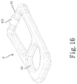
- FIG. 16 is an enlarged elevational view of the pull tab in accordance with the second embodiment of the present invention.
- FIG. 17 is an elevational view of a part of the second embodiment of the present invention, showing a finger strip provided at the top end of the right top stop.
- a combined zipper top stop and pull tab safety protection structure in accordance with a first embodiment of the present invention comprises a left top stop 3 located on a top end of a left zipper tape 1 , a right top stop 4 located on a top end of a right zipper tape 2 , a zipper slider 5 used to close/open the left zipper tape 1 and the right zipper tape 2 , and a pull tab 6 coupled to the zipper slider 5 .
- the left top stop 3 and the right top stop 4 are made by polyoxymethylene (POM) thermoplastic injection molding, respectively providing a pin hole 41 (see FIG. 2 ) or a mating pin 31 (see FIG. 5 ) for interlocking.
- POM polyoxymethylene
- the pin hole 41 and the pin 31 can be configured having a non-circular cross section, such as triangular or polygonal cross section.
- the right top stop 4 is disposed above the left top stop 3 .
- the right top stop 4 further has an engagement block 42 located on a top surface thereof.
- the engagement block 42 is provided with at least one transverse groove 420 (refer to FIG. 4 to FIG. 5 ) to make the engagement block 42 elastic.
- the zipper slider 5 is an auto lock zipper slider.
- the pull tab 6 is a rigid material, having an engagement hole 62 for engagement with the engagement block 42 of the right top stop 4 (see FIGS. 3-5 ).
- the engagement design between the engagement hole 62 and the engagement block 42 and the engagement design between the pin hole 41 and the pin 31 achieve the security protection of the interlocking of the left, right, upper and lower sides.
- Magnetic members 311 ; 421 that are magnetically attractable to each other are respectively provided at the left top stop 3 near the pin 31 and the right top stop 4 near the pin hole 41 (see FIG. 5 ), enabling the left top stop 3 , the right top stop 4 and the pull tab 5 to be secured together.
- the zipper slider 5 can be a no lock zipper slider that has the pull tab 6 integrally formed therein by insert molding (see FIGS. 6-8 ).
- the pull tab 6 is made of an elastic material by insert molding. It is elastic, the engagement block 42 of the right top stop 4 does not need to provide the transverse groove 420 shown in FIGS. 3-5 .
- the left top stop and right top stop structure is used with a reverse coil zipper YG slider semi auto design.
- the combined zipper top stop and pull tab safety protection structure comprises a left top stop 3 located on a top end of a left zipper tape 1 , a right top stop 4 located on a top end of a right zipper tape 2 , a zipper slider 5 used to close/open the left zipper tape 1 and the right zipper tape 2 , and a pull tab 6 coupled to the zipper slider 5 .
- the left top stop 3 and the right top stop 4 are made by polyoxymethylene (POM) thermoplastic injection molding, respectively providing a pin hole 41 (see FIG. 10 ) or a mating pin 31 (see FIG. 11 ) for interlocking.
- POM polyoxymethylene
- the pin hole 41 and the pin 31 can be configured having a non-circular cross section, such as triangular or polygonal cross section.
- the right top stop 4 is disposed above the left top stop 3 .
- the right top stop 4 further has an engagement block 42 located on a top surface thereof.
- the engagement block 42 can be aesthetically pleasing for any shape.
- the pull tab 6 has an engagement hole 62 located on one end thereof, a transverse bar 61 located on an opposite end thereof, and a reverse cam 611 located on the transverse bar 61 (see FIG. 16 ).
- a spring plate 7 is provided having one end 71 thereof affixed to the zipper slider 5 and an opposite end 72 thereof movable relative to the zipper slider 5 (see FIGS.
- the zipper slide 5 has a locating hole 51 (see FIGS. 13-15 ) for the mounting of the spring plate 7 .
- the one end 71 of the spring plate 7 is affixed to an inside wall of the locating hole 51 .
- the opposite end 72 of the spring plate 7 is curved for engagement with the reverse cam 611 at the transverse bar 61 of the pull tab 6 and terminating in a plug tip 721 (see FIGS. 13-15 ) for insertion into an insertion hole 521 on a top wall 52 of the zipper slider 5 .
- the insertion hole 521 is in communication with an internal cavity 53 of the zipper slider 5 (see FIGS. 13-15 ).
- the opposite end 72 of the spring plate 7 can be inserted into or moved out of the internal cavity 53 of the zipper slider 5 .
- the right top stop 4 further provides a finger strip 412 at a top end thereof. Through the finger strip 412 , the right top stop 4 can be conveniently operated with the finger or fingernail to disengage the pin hole 41 from the pin 31 of the left top stop 3 .
- the method of using the combined zipper top stop and pull tab safety protection structure in accordance with the present invention includes the steps of:
- the pull tab 6 of the zipper slider 5 can be reversed to force the engagement hole 62 into engagement with the engagement block 42 of the right top stop 4 after engagement between the left top stop 3 and the right top stop 4 , achieving the security protection of the interlocking of the left, right, upper and lower sides.
Landscapes
- Bag Frames (AREA)
- Slide Fasteners (AREA)
Abstract
Description
- a. Force the
pin 31 of the lefttop stop 3 into engagement with thepin hole 41 of the righttop stop 4 manually (seeFIG. 11 ). - b. Move the
zipper slider 5 to the box (not shown) and insert the pin (not shown) into the box, and then pull thezipper slider 5 to close the left and right zipper tapes, and then force theengagement hole 62 of thepull tab 6 into engagement with theengagement block 42 of the right top stop 4 (seeFIGS. 12 and 13 ). - c. In the aforesaid procedures, the
reverse cam 611 at thetransverse bar 61 of thepull tab 6 is turned upward to about 45-degree angle relative to the spring plate 7 (seeFIG. 14 ), causing theengagement hole 62 of thepull tab 6 to be forced into engagement with theengagement block 42 of the righttop stop 4 to prohibit thezipper slider 5 from displacement. At the same time, alatch portion 33 of the lefttop stop 3 and alatch portion 43 of the righttop stop 4 are inserted into theinternal cavity 53 of thezipper slider 5 to stop thezipper slider 5 from displacement. Subject to the engagement between theengagement hole 62 and theengagement block 42 and the engagement between thepin hole 41 and thepin 31, the lefttop stop 3 and the righttop stop 4 are prohibited from relative movement horizontally and vertically, maintaining the lateral force stability. - d. When dismounting the zipper, use the fingers to disengage the
engagement hole 62 of thepull tab 6 from theengagement block 42 of the righttop stop 4 so as to unlock thezipper slider 5, then move thezipper slider 5 downward for a small distance, and then use the finger or fingernail to lift thefinger strip 412 of the righttop stop 4 in disengaging thepin hole 41 of the righttop stop 4 from thepin 31 of the lefttop stop 3. - e. Separate the left and right zipper tapes to disengage the pin from the box.
Claims (7)
Applications Claiming Priority (3)
| Application Number | Priority Date | Filing Date | Title |
|---|---|---|---|
| CN201821141447U | 2018-07-16 | ||
| CN201821141447.0U CN208523931U (en) | 2018-07-16 | 2018-07-16 | Stop structure on interlockable left and right |
| CN201821141447.0 | 2018-07-16 |
Publications (2)
| Publication Number | Publication Date |
|---|---|
| US20200015553A1 US20200015553A1 (en) | 2020-01-16 |
| US10820668B2 true US10820668B2 (en) | 2020-11-03 |
Family
ID=65388136
Family Applications (1)
| Application Number | Title | Priority Date | Filing Date |
|---|---|---|---|
| US16/433,238 Expired - Fee Related US10820668B2 (en) | 2018-07-16 | 2019-06-06 | Combined zipper top stop and pull tab safety protection structure and the method of use thereof |
Country Status (2)
| Country | Link |
|---|---|
| US (1) | US10820668B2 (en) |
| CN (1) | CN208523931U (en) |
Cited By (1)
| Publication number | Priority date | Publication date | Assignee | Title |
|---|---|---|---|---|
| WO2026017457A1 (en) | 2024-07-18 | 2026-01-22 | Christen | Retention system for a slide fastener |
Families Citing this family (7)
| Publication number | Priority date | Publication date | Assignee | Title |
|---|---|---|---|---|
| PL3629822T3 (en) * | 2017-06-02 | 2025-11-12 | Mrm Hk Limited | ZIPPER |
| CN108577057A (en) * | 2018-07-16 | 2018-09-28 | 芊茂(浙江)拉链有限公司 | Stop structure on interlockable left and right |
| CN110226811B (en) * | 2019-06-26 | 2022-01-11 | 浙江宇伟拉链有限公司 | Zipper |
| CN110558774A (en) * | 2019-08-01 | 2019-12-13 | 汕头大学 | Mosquito net with fluorescent night vision zipper |
| US11432622B2 (en) * | 2020-03-17 | 2022-09-06 | Nike, Inc. | Releasable coupling device |
| US20240122308A1 (en) * | 2022-10-14 | 2024-04-18 | Shannon McKeown | Zipper Assist Device |
| EP4686428A1 (en) | 2024-08-01 | 2026-02-04 | YKK Corporation | Zipper |
Citations (5)
| Publication number | Priority date | Publication date | Assignee | Title |
|---|---|---|---|---|
| US2087045A (en) * | 1934-07-20 | 1937-07-13 | Roberts Robert Goodman | Fastening for slit openings in garments |
| US2915798A (en) * | 1956-12-14 | 1959-12-08 | Jr Chester H Hewitt | Tab lock for slide-fasteners |
| US5400480A (en) * | 1993-12-16 | 1995-03-28 | Futch, Iii; James M. | Device for attaching an article of clothing |
| US20090229090A1 (en) * | 2008-03-13 | 2009-09-17 | Riri, S.A. | Slide Fastener and a Top Stop for a Slide Fastener |
| US20120246890A1 (en) * | 2010-09-27 | 2012-10-04 | John Luis Hernandez | Zipper with attached fastener |
-
2018
- 2018-07-16 CN CN201821141447.0U patent/CN208523931U/en active Active
-
2019
- 2019-06-06 US US16/433,238 patent/US10820668B2/en not_active Expired - Fee Related
Patent Citations (5)
| Publication number | Priority date | Publication date | Assignee | Title |
|---|---|---|---|---|
| US2087045A (en) * | 1934-07-20 | 1937-07-13 | Roberts Robert Goodman | Fastening for slit openings in garments |
| US2915798A (en) * | 1956-12-14 | 1959-12-08 | Jr Chester H Hewitt | Tab lock for slide-fasteners |
| US5400480A (en) * | 1993-12-16 | 1995-03-28 | Futch, Iii; James M. | Device for attaching an article of clothing |
| US20090229090A1 (en) * | 2008-03-13 | 2009-09-17 | Riri, S.A. | Slide Fastener and a Top Stop for a Slide Fastener |
| US20120246890A1 (en) * | 2010-09-27 | 2012-10-04 | John Luis Hernandez | Zipper with attached fastener |
Cited By (2)
| Publication number | Priority date | Publication date | Assignee | Title |
|---|---|---|---|---|
| WO2026017457A1 (en) | 2024-07-18 | 2026-01-22 | Christen | Retention system for a slide fastener |
| FR3164610A1 (en) | 2024-07-18 | 2026-01-23 | Christen | Zipper locking system |
Also Published As
| Publication number | Publication date |
|---|---|
| CN208523931U (en) | 2019-02-22 |
| US20200015553A1 (en) | 2020-01-16 |
Similar Documents
| Publication | Publication Date | Title |
|---|---|---|
| US10820668B2 (en) | Combined zipper top stop and pull tab safety protection structure and the method of use thereof | |
| US9545134B1 (en) | Waterproof zipper | |
| US8844101B2 (en) | Reverse opening slide fastener | |
| US7506419B2 (en) | Buckle using a slide cover type female buckle member | |
| CN103369981B (en) | Zipper with split insert | |
| TWI276407B (en) | Slider, slide fastener having the sliders, and bag having the slide fastener | |
| WO2019186665A1 (en) | Buckle | |
| CN103491820A (en) | Slider for slide fastener | |
| TW201023786A (en) | Slide zipper with slider insert | |
| CN108625688A (en) | A kind of slim padlock of external | |
| CN108209064B (en) | Slider fastener | |
| CN111936007B (en) | Slider and slide fastener provided with same | |
| TWI544880B (en) | The slide fastener with | |
| CN206333468U (en) | Zipper head combined structure and elastic piece thereof | |
| CN107432531A (en) | Zipper head combined structure and sliding assembly thereof | |
| CN211354117U (en) | Double-opening zipper | |
| US20180110310A1 (en) | Rectangular bag | |
| CN204191750U (en) | Invisible zipper head combined structure for improving positioning effect and sliding part thereof | |
| EP3556241B1 (en) | Semi-circular zipper and sliders used cooperatively | |
| CN210054865U (en) | Press hasp | |
| CN108813831A (en) | zipper | |
| CN111918580B (en) | Sliders and zippers equipped with such sliders | |
| CN103156338B (en) | Zipper sliding block, zipper head using zipper sliding block and double-opening zipper | |
| CN205831258U (en) | Zipper head combined structure and sliding assembly thereof | |
| CN217565174U (en) | Fastener device |
Legal Events
| Date | Code | Title | Description |
|---|---|---|---|
| AS | Assignment |
Owner name: GENMORE ZIPPER CORPORATION, TAIWAN Free format text: ASSIGNMENT OF ASSIGNORS INTEREST;ASSIGNOR:WANG, LIEN-CHOU;REEL/FRAME:049393/0306 Effective date: 20190531 |
|
| FEPP | Fee payment procedure |
Free format text: ENTITY STATUS SET TO UNDISCOUNTED (ORIGINAL EVENT CODE: BIG.); ENTITY STATUS OF PATENT OWNER: SMALL ENTITY |
|
| FEPP | Fee payment procedure |
Free format text: ENTITY STATUS SET TO SMALL (ORIGINAL EVENT CODE: SMAL); ENTITY STATUS OF PATENT OWNER: SMALL ENTITY |
|
| STPP | Information on status: patent application and granting procedure in general |
Free format text: DOCKETED NEW CASE - READY FOR EXAMINATION |
|
| STPP | Information on status: patent application and granting procedure in general |
Free format text: NON FINAL ACTION MAILED |
|
| STPP | Information on status: patent application and granting procedure in general |
Free format text: NOTICE OF ALLOWANCE MAILED -- APPLICATION RECEIVED IN OFFICE OF PUBLICATIONS |
|
| STPP | Information on status: patent application and granting procedure in general |
Free format text: PUBLICATIONS -- ISSUE FEE PAYMENT VERIFIED |
|
| STCF | Information on status: patent grant |
Free format text: PATENTED CASE |
|
| FEPP | Fee payment procedure |
Free format text: MAINTENANCE FEE REMINDER MAILED (ORIGINAL EVENT CODE: REM.); ENTITY STATUS OF PATENT OWNER: SMALL ENTITY |
|
| LAPS | Lapse for failure to pay maintenance fees |
Free format text: PATENT EXPIRED FOR FAILURE TO PAY MAINTENANCE FEES (ORIGINAL EVENT CODE: EXP.); ENTITY STATUS OF PATENT OWNER: SMALL ENTITY |
|
| STCH | Information on status: patent discontinuation |
Free format text: PATENT EXPIRED DUE TO NONPAYMENT OF MAINTENANCE FEES UNDER 37 CFR 1.362 |
|
| FP | Lapsed due to failure to pay maintenance fee |
Effective date: 20241103 |