US10819955B2 - Aircraft provided with a surveillance system - Google Patents
Aircraft provided with a surveillance system Download PDFInfo
- Publication number
- US10819955B2 US10819955B2 US15/463,892 US201715463892A US10819955B2 US 10819955 B2 US10819955 B2 US 10819955B2 US 201715463892 A US201715463892 A US 201715463892A US 10819955 B2 US10819955 B2 US 10819955B2
- Authority
- US
- United States
- Prior art keywords
- panoramic camera
- aircraft
- camera
- objective lens
- access door
- Prior art date
- Legal status (The legal status is an assumption and is not a legal conclusion. Google has not performed a legal analysis and makes no representation as to the accuracy of the status listed.)
- Active, expires
Links
- 230000002093 peripheral effect Effects 0.000 claims description 15
- 238000000149 argon plasma sintering Methods 0.000 claims description 7
- 230000007423 decrease Effects 0.000 claims description 4
- 239000000463 material Substances 0.000 claims description 4
- 238000009434 installation Methods 0.000 description 3
- 238000012423 maintenance Methods 0.000 description 3
- 238000012544 monitoring process Methods 0.000 description 3
- 239000000779 smoke Substances 0.000 description 3
- 230000033228 biological regulation Effects 0.000 description 2
- 230000003287 optical effect Effects 0.000 description 2
- 230000009286 beneficial effect Effects 0.000 description 1
- 230000000295 complement effect Effects 0.000 description 1
- 230000005494 condensation Effects 0.000 description 1
- 238000009833 condensation Methods 0.000 description 1
- 239000000470 constituent Substances 0.000 description 1
- 238000001514 detection method Methods 0.000 description 1
- 235000013305 food Nutrition 0.000 description 1
- 238000005286 illumination Methods 0.000 description 1
- 239000002184 metal Substances 0.000 description 1
- 238000000034 method Methods 0.000 description 1
- 239000007787 solid Substances 0.000 description 1
- 238000001429 visible spectrum Methods 0.000 description 1
- 230000000007 visual effect Effects 0.000 description 1
Images


Classifications
-
- H—ELECTRICITY
- H04—ELECTRIC COMMUNICATION TECHNIQUE
- H04N—PICTORIAL COMMUNICATION, e.g. TELEVISION
- H04N7/00—Television systems
- H04N7/18—Closed-circuit television [CCTV] systems, i.e. systems in which the video signal is not broadcast
- H04N7/181—Closed-circuit television [CCTV] systems, i.e. systems in which the video signal is not broadcast for receiving images from a plurality of remote sources
-
- G—PHYSICS
- G02—OPTICS
- G02B—OPTICAL ELEMENTS, SYSTEMS OR APPARATUS
- G02B13/00—Optical objectives specially designed for the purposes specified below
- G02B13/06—Panoramic objectives; So-called "sky lenses" including panoramic objectives having reflecting surfaces
-
- G—PHYSICS
- G03—PHOTOGRAPHY; CINEMATOGRAPHY; ANALOGOUS TECHNIQUES USING WAVES OTHER THAN OPTICAL WAVES; ELECTROGRAPHY; HOLOGRAPHY
- G03B—APPARATUS OR ARRANGEMENTS FOR TAKING PHOTOGRAPHS OR FOR PROJECTING OR VIEWING THEM; APPARATUS OR ARRANGEMENTS EMPLOYING ANALOGOUS TECHNIQUES USING WAVES OTHER THAN OPTICAL WAVES; ACCESSORIES THEREFOR
- G03B11/00—Filters or other obturators specially adapted for photographic purposes
- G03B11/04—Hoods or caps for eliminating unwanted light from lenses, viewfinders or focusing aids
- G03B11/045—Lens hoods or shields
-
- G—PHYSICS
- G03—PHOTOGRAPHY; CINEMATOGRAPHY; ANALOGOUS TECHNIQUES USING WAVES OTHER THAN OPTICAL WAVES; ELECTROGRAPHY; HOLOGRAPHY
- G03B—APPARATUS OR ARRANGEMENTS FOR TAKING PHOTOGRAPHS OR FOR PROJECTING OR VIEWING THEM; APPARATUS OR ARRANGEMENTS EMPLOYING ANALOGOUS TECHNIQUES USING WAVES OTHER THAN OPTICAL WAVES; ACCESSORIES THEREFOR
- G03B15/00—Special procedures for taking photographs; Apparatus therefor
- G03B15/006—Apparatus mounted on flying objects
-
- G—PHYSICS
- G03—PHOTOGRAPHY; CINEMATOGRAPHY; ANALOGOUS TECHNIQUES USING WAVES OTHER THAN OPTICAL WAVES; ELECTROGRAPHY; HOLOGRAPHY
- G03B—APPARATUS OR ARRANGEMENTS FOR TAKING PHOTOGRAPHS OR FOR PROJECTING OR VIEWING THEM; APPARATUS OR ARRANGEMENTS EMPLOYING ANALOGOUS TECHNIQUES USING WAVES OTHER THAN OPTICAL WAVES; ACCESSORIES THEREFOR
- G03B15/00—Special procedures for taking photographs; Apparatus therefor
- G03B15/02—Illuminating scene
- G03B15/03—Combinations of cameras with lighting apparatus; Flash units
-
- G—PHYSICS
- G03—PHOTOGRAPHY; CINEMATOGRAPHY; ANALOGOUS TECHNIQUES USING WAVES OTHER THAN OPTICAL WAVES; ELECTROGRAPHY; HOLOGRAPHY
- G03B—APPARATUS OR ARRANGEMENTS FOR TAKING PHOTOGRAPHS OR FOR PROJECTING OR VIEWING THEM; APPARATUS OR ARRANGEMENTS EMPLOYING ANALOGOUS TECHNIQUES USING WAVES OTHER THAN OPTICAL WAVES; ACCESSORIES THEREFOR
- G03B37/00—Panoramic or wide-screen photography; Photographing extended surfaces, e.g. for surveying; Photographing internal surfaces, e.g. of pipe
-
- H—ELECTRICITY
- H04—ELECTRIC COMMUNICATION TECHNIQUE
- H04N—PICTORIAL COMMUNICATION, e.g. TELEVISION
- H04N23/00—Cameras or camera modules comprising electronic image sensors; Control thereof
- H04N23/50—Constructional details
- H04N23/51—Housings
-
- H—ELECTRICITY
- H04—ELECTRIC COMMUNICATION TECHNIQUE
- H04N—PICTORIAL COMMUNICATION, e.g. TELEVISION
- H04N23/00—Cameras or camera modules comprising electronic image sensors; Control thereof
- H04N23/56—Cameras or camera modules comprising electronic image sensors; Control thereof provided with illuminating means
-
- H—ELECTRICITY
- H04—ELECTRIC COMMUNICATION TECHNIQUE
- H04N—PICTORIAL COMMUNICATION, e.g. TELEVISION
- H04N23/00—Cameras or camera modules comprising electronic image sensors; Control thereof
- H04N23/57—Mechanical or electrical details of cameras or camera modules specially adapted for being embedded in other devices
-
- H—ELECTRICITY
- H04—ELECTRIC COMMUNICATION TECHNIQUE
- H04N—PICTORIAL COMMUNICATION, e.g. TELEVISION
- H04N23/00—Cameras or camera modules comprising electronic image sensors; Control thereof
- H04N23/60—Control of cameras or camera modules
- H04N23/698—Control of cameras or camera modules for achieving an enlarged field of view, e.g. panoramic image capture
-
- H04N5/2252—
-
- H04N5/2256—
-
- H04N5/2257—
-
- H04N5/23238—
-
- G—PHYSICS
- G03—PHOTOGRAPHY; CINEMATOGRAPHY; ANALOGOUS TECHNIQUES USING WAVES OTHER THAN OPTICAL WAVES; ELECTROGRAPHY; HOLOGRAPHY
- G03B—APPARATUS OR ARRANGEMENTS FOR TAKING PHOTOGRAPHS OR FOR PROJECTING OR VIEWING THEM; APPARATUS OR ARRANGEMENTS EMPLOYING ANALOGOUS TECHNIQUES USING WAVES OTHER THAN OPTICAL WAVES; ACCESSORIES THEREFOR
- G03B2215/00—Special procedures for taking photographs; Apparatus therefor
- G03B2215/05—Combinations of cameras with electronic flash units
- G03B2215/0503—Built-in units
Definitions
- the present invention relates to an aircraft provided with a surveillance system for the surveillance of a plurality of zones of interest inside a closed space of the aircraft.
- the invention finds a particularly advantageous application in the case of an aircraft of the airplane type, but is applicable to any type of aircraft.
- the invention finds itself to be entirely advantageous notably for application to the surveillance of access doors to an airplane closed space, including the doors situated near the flightdeck of the airplane, such as for example a door separating the flightdeck from the rest of the airplane.
- Such a surveillance system has therefore to be able to observe a zone of interest associated with a door providing access to the flightdeck, separating said flightdeck from a cabin of the airplane, which is itself generally intended to accommodate passengers.
- a first camera is positioned in such a way that the zone of interest associated with the door providing access to the flightdeck is in the field of view of said camera.
- the zone of interest associated with the door providing access to the flightdeck corresponds to a zone situated in front of said access door, outside the flightdeck.
- the first camera is, for example, situated just above the flightdeck access door or opposite said access door and facing toward it.
- a second access door allowing the airplane cabin to be entered from outside, also to be under surveillance in order to provide members of the flight crew with visual information regarding the movement of passengers or equipment.
- the surveillance systems conventionally employed comprise for this purpose a second camera positioned in such a way that a zone of interest associated with said second access door is in its field of view.
- a conventional commercial airplane comprises:
- the zone of interest associated with the lateral access door of the airplane corresponds to a zone situated in front of said lateral access door, inside the cabin.
- the second camera is, for example, situated just over this lateral access door, or opposite it and at an opposite end of the transverse aisle.
- the conventional surveillance systems usually comprise a third camera situated at the opposite end of the transverse aisle to the second camera.
- This third camera is directed toward the transverse aisle and is used to observe those portions of the transverse aisle that cannot be seen by the other cameras and/or to observe an additional lateral access door likewise opening onto the transverse aisle, for example an emergency exit of the airplane.
- Such surveillance systems make it possible to provide what is generally a satisfactory view of the part of the cabin near the flightdeck.
- Such surveillance systems are complicated to install in an airplane and require a great deal of wiring in order to link up all the cameras of the surveillance system, and a great deal of maintenance operations on the various elements of said surveillance system.
- the invention seeks to provide a surveillance system that provides an improved view of the interior of an aircraft.
- the invention also seeks to offer a surveillance system which has the advantage, in certain embodiments, of being simpler to install than the surveillance systems of the prior art, while at the same time allowing numerous zones of interest to be observed.
- a closed space may be a flightdeck of the aircraft, a passenger cabin, a hold, a landing gear bay, etc.
- a zone of interest may be associated with a door providing access to the closed space, in which case it is said access door and/or a zone in the immediate vicinity of this door.
- a zone of interest may also correspond to an aisle of the aircraft, to a galley (a zone in which the cabin crew prepare and store food products), etc.
- the surveillance system comprises a camera that has a panoramic field of view and is referred to as a “panoramic camera”.
- a panoramic camera means a camera that has a field of view with an angular width in excess of 150°.
- the panoramic camera advantageously has a very wide field of view, with an angular width in excess of 240°.
- the panoramic camera is sited in such a way that at least one zone of interest is in its field of view.
- the panoramic camera will make it possible to have a wide view of this zone of interest.
- the panoramic camera may also be sited in such a way that at least two different zones of interest of the closed space are in its field of view.
- the surveillance system thus allows the surveillance of several zones of interest using just one camera.
- the closed space comprises at least two distant, which means non-adjacent, access doors and the panoramic camera is sited in such a way that at least two zones of interest associated with different access doors are in its field of view.
- the wide field of view of the camera advantageously allows the surveillance system to have practically no more dead corners, i.e. allows it to be able, for each access door concerned, to observe a very wide zone of interest, thus greatly reducing the volume of the zones in which an individual could conceal himself, near the door, without being visible to the panoramic camera according to the invention.
- the closed space is the passenger cabin of the aircraft
- a first access door referred to as a lateral door
- a second access door is a door providing access from the cabin to the flightdeck.
- the camera is located in the passenger cabin, preferably near the flightdeck.
- the aircraft comprises, in the passenger cabin, a transverse aisle adjacent to the flightdeck, and a longitudinal aisle which intersect one another at an intersection zone.
- a first access door is situated at one end of the transverse aisle and a second access door, providing access to the flightdeck, is situated at one end of the longitudinal aisle.
- the panoramic camera is sited at the intersection zone so that a zone of interest associated with the first access door and a zone of interest associated with the second access door are in its field of view.
- This topological location of the panoramic camera allows the surveillance system to cover the zones of interest which are associated with the two access doors and, in particular, a zone of interest associated with the second access door that provides access to the flightdeck.
- This topological location of the panoramic camera is therefore advantageous for creating a flightdeck or cockpit door surveillance system (CDSS).
- CDSS flightdeck or cockpit door surveillance system
- the surveillance system further comprises a camera that has a non-panoramic field of view (which means to say a field of view of an angular width equal to or less than 150°), referred to as a “non-panoramic camera” which is distant from the panoramic camera and sited in such a way as to observe a zone of interest that is in the field of view of the panoramic camera.
- a non-panoramic field of view which means to say a field of view of an angular width equal to or less than 150°
- the non-panoramic camera makes it possible to observe a zone of interest lying in the field of view of the panoramic camera from a different viewpoint than that of said panoramic camera, and possibly with better resolution than said panoramic camera.
- the panoramic camera and the non-panoramic camera complement one another perfectly.
- the panoramic camera provides an overview of a scene, while the non-panoramic camera provides a more detailed view of a pre-defined zone within this scene.
- the non-panoramic camera can be sited so that it observes a zone of interest situated at the end of the longitudinal aisle, in front of the second access door that provides access to said flightdeck.
- the panoramic camera for example sited in the ceiling and aimed at a floor of the zone of intersection allows generalized monitoring of access to the flightdeck and makes it possible to detect the presence of an individual seeking to access the flightdeck.
- the non-panoramic camera can then be used to identify the individual who is seeking to access the flightdeck.
- the non-panoramic camera is, for example, sited in the second access door or in a bulkhead surrounding said second access door.
- the panoramic camera has a field of view that is wide enough also to observe the transverse aisle on the opposite side of said panoramic camera to the first access door and/or the longitudinal aisle on the opposite side of said panoramic camera to the second access door.
- the system thus has the advantage of being able to monitor the transverse aisle and/or the longitudinal aisle without needing a further camera.
- the aircraft comprises a third access door at another end of the transverse aisle, and the panoramic camera has a field of view that is wide enough also to observe said third access door.
- the panoramic camera has a field of view that is wide enough also to observe said third access door.
- the aircraft comprises a second longitudinal aisle intersecting with the transverse aisle at a second zone of intersection
- the surveillance system comprises another panoramic camera sited in the second zone of intersection so as to observe the second longitudinal aisle.
- a second panoramic camera advantageously makes it possible to achieve redundancy in the monitoring of the transverse aisle and of the two doors for accessing the aircraft cabin from the outside. This redundancy of data offers the advantage that individuals wishing to access the flightdeck can be viewed from several viewpoints and thus identified better.
- the surveillance system comprises a panoramic camera located in a hold of the aircraft.
- a panoramic camera situated in the hold of the aircraft makes it possible to monitor the movement of luggage or even detect the presence of intruders or incidents that have occurred in the hold.
- the surveillance system comprises a panoramic camera located in a landing gear bay of the aircraft.
- a panoramic camera makes it possible to monitor the operation of the landing gear or even detect the presence of intruders in the landing gear bay.
- the surveillance system comprises a panoramic camera sited in the passenger cabin of the aircraft, i.e. in the zone of the passenger cabin in which the seats for the passengers are located.
- At least one panoramic camera is housed in a ceiling of the closed space in which said camera is situated.
- a camera situated in the ceiling has the notable advantage of being sited in a fairly uncluttered part of the aircraft, whatever closed space of the aircraft is being considered.
- the present invention proves to be far more advantageous than the devices proposed by the prior art which require installation in more cluttered locations such as the bulkheads situated over the access doors.
- At least one panoramic camera comprises a fixed camera associated with a fixed objective lens capable simultaneously of focusing the entire panoramic field of view onto the fixed camera.
- a fixed camera associated with a fixed objective lens capable simultaneously of focusing the entire panoramic field of view onto the fixed camera.
- Such arrangements allow all of the panoramic field of view of this panoramic camera to be captured simultaneously, with each captured image representing the entirety of the panoramic field of view.
- At least one panoramic camera has a field of view which is panoramic both in azimuth, about an axis of the panoramic camera, and in elevation in a plane containing said axis of the panoramic camera.
- the angular width of said field of view is greater than 150° both in elevation and in azimuth.
- At least one panoramic camera has a field of view in azimuth with an angular width of 360° about an axis of the panoramic camera.
- a field of view as broad as this advantageously allows the panoramic camera or cameras of the surveillance system to observe very broad zones of interest notably associated with the access doors.
- At least one panoramic camera is sensitive in the infrared wavelengths.
- a panoramic camera of this type advantageously allows image processing to be carried out, notably to detect fire or smoke, and thus protect the passengers or their luggage or even certain parts of the aircraft.
- the panoramic camera may also act as a thermographic sensor, detecting hotspots by graphics inserted over the viewed stream of images, and thus detect the presence of smoke or individuals.
- At least one panoramic camera is preferably equipped with a lighting element.
- the image processing that can be performed by the surveillance system may involve processing operations outside the visible spectrum, for example in the infrared domain. In these wavelengths, it is particularly advantageous to associate a lighting element with one or more panoramic cameras in order to improve the processing.
- At least one panoramic camera is sited inside a sealed box, which prevents certain damage to the panoramic camera that could be caused by condensation likely to form on it were such a box not to be present.
- At least one panoramic camera presents little distortion, making it possible to obtain a view close to human vision while at the same time having a panoramic field of view. Thus it will be easier for the flight crew to interpret the images.
- the panoramic camera further comprises a lighting element and a housing in which are arranged said lighting element and the fixed objective lens, and the fixed objective lens is arranged in a protruding part of the housing that extends forward beyond the lighting element, such that said lighting element is recessed in the housing relative to the fixed objective lens and is not in the field of view of said fixed objective lens.
- the protruding part is of tubular shape and made of opaque material
- the fixed objective lens is arranged inside said protruding part of the housing.
- the housing comprises a peripheral groove surrounding the protruding part and the lighting element is arranged in said peripheral groove.
- the panoramic camera comprises a plurality of lighting elements arranged in the peripheral groove.
- the panoramic camera comprises a panomorph objective lens.
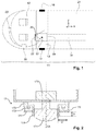
- FIG. 1 a schematic representation of an aircraft of the airplane type according to one preferred embodiment of the invention
- FIG. 2 a cross section schematic representation of a preferred embodiment of a panoramic camera to be used in an aircraft;
- FIG. 3 a schematic perspective view of a housing of the panoramic camera of FIG. 2 ;
- FIG. 4 a schematic representation of an aircraft of the type according to a second preferred embodiment of the invention.
- FIG. 1 illustrates a preferred embodiment of the invention and depicts the forward part of an aircraft 11 , the other parts of which have not been depicted.
- the aircraft comprises a main cabin 21 , intended notably to accommodate passengers, and a flightdeck 12 , separated from the main cabin by an access door 22 .
- a frame of reference comprising three axes x, y, z is associated with the aircraft 11 .
- the axis x is a longitudinal axis of the aircraft 11 .
- the axis y is an axis orthogonal to the axis x, forming with the axis x a plane substantially parallel to a floor of the aircraft 11 .
- the axis z (not indicated in the figures) is orthogonal to the axis x and to the axis y and is therefore substantially orthogonal to the floor of the aircraft 11 .
- a lateral access door 14 provides access to the cabin of the aircraft 11 from outside. It opens onto a transverse aisle 13 running substantially along the axis y, adjoining the flightdeck 12 .
- the transverse aisle 13 services, on one side, a longitudinal aisle 15 that runs substantially along the longitudinal axis x, and, on the other side, the access door 22 providing access to the flightdeck 12 .
- a third door 16 which acts as an emergency exit is also present at one end of the transverse aisle 13 which is the opposite end to the lateral access door 14 .
- the access door 22 generally involves security measures, for example is reinforced.
- the aircraft 11 further comprises a surveillance system.
- This surveillance system comprises a camera having a panoramic field of view and is referred to as “panoramic camera” 17 .
- a “panoramic camera” means a camera that has a field of view with an angular width in excess of 150°, preferably in excess of 240°.
- the panoramic camera 17 is used to observe a zone of interest associated with the access door 22 providing access to the flightdeck 12 and a zone of interest associated with the lateral access door 14 .
- the panoramic camera 17 is, for example, connected to a computer 18 able to process a stream of images originating from the camera in order to display it on at least one display screen 20 . There is nothing to preclude, in other examples and if the stream of images does not need to be processed, connecting the panoramic camera 17 directly to the display screen 20 , without passing via a computer 18 .
- the display screen 20 is in the flightdeck 12 . There is nothing to preclude, according to other examples, having the display screen 20 situated elsewhere in the aircraft 11 than in the flightdeck. Further, if the surveillance system comprises several display screens, these may be situated at various points within the aircraft 11 .
- the panoramic camera 17 may be a camera capable of rotating about a fixed axis, or alternatively may comprise a fixed (immobile) camera associated with a mirror system capable of rotating. In such cases, the panoramic field of view is observed by rotating the mobile camera and/or the mobile mirror system and by capturing successive images each representing part of the panoramic field of view.
- the panoramic camera comprises a fixed camera associated with a fixed objective lens able to focus simultaneously all of the panoramic field of view and comprising diffractive, refractive optical elements, optical elements involving concave and/or convex mirrors, involving half-silvered mirrors, etc.
- diffractive, refractive optical elements optical elements involving concave and/or convex mirrors, involving half-silvered mirrors, etc.
- each captured image represents all of the panoramic field of view.
- all the elements that make up the panoramic camera 17 are preferably immobile, and said panoramic camera 17 does not need to comprise mechanical and electrical means for driving the camera or its objective lens, which drive means are often bulky and require regular maintenance.
- the panoramic camera 17 has a fixed camera associated with a fixed panomorph objective lens able to focus simultaneously all of the panoramic field of view.
- suitable panomorph objective lenses are commercialized, inter alia, by ImmerVision®.
- Panomorph objective lenses are particularly advantageous for surveillance systems since they allow for spatially differentiated resolution in the field of view of the panoramic camera 17 .
- the pixel density is not necessarily the same in every direction in the field of view, and it is possible e.g. to have a high number of pixels per steradian in the direction of a zone of interest having a high priority, and to have a low number of pixels per steradian in the direction of a zone of interest having a low priority.
- Spatially differentiated resolution is not possible with e.g. fisheye objective lenses.
- the zone of interest associated with an access door 14 , 22 corresponds to said access door, and to a zone situated in the cabin in front of and around this door.
- the panoramic camera 17 is sited in the cabin 21 in such a way that the zones of interest associated with each of the access doors 14 and 22 lie in its field of view.
- the panoramic camera 17 preferably has a panoramic field of view about an axis of the camera, referred to as “camera axis” that is substantially parallel to the axis z (the axis z being orthogonal to the axes x and y).
- the field of view of the panoramic camera 17 is of an angular width greater than 150° about the camera axis (in azimuth).
- the width of the field of view of the panoramic camera 17 about this axis is substantially equal to 360°.
- the panoramic camera 17 may advantageously be placed in the ceiling, which is generally fairly uncluttered.
- the present invention proves to be far more advantageous than the devices proposed by the prior art, which require installation in more cluttered areas such as the bulkheads over the access doors.
- the panoramic camera 17 makes it possible to obtain a panoramic field of view not only about the camera axis (in azimuth) but also with respect to the camera axis in a plane containing said camera axis (in elevation). Specifically, such a panoramic camera makes it possible to look in numerous directions in azimuth and in elevation. For example, if a panoramic camera 17 has a panoramic field of view of an angular width of substantially 360° in azimuth, and substantially 180° in elevation, such a panoramic camera will make it possible to observe a solid angle of around 2 ⁇ steradians, namely a substantially hemispherical field of view.
- the panoramic camera example given in Patent Application FR-A-2 902 592 makes it possible to have a field of view of an angular width of substantially 360° in azimuth and almost 150° in elevation.
- the panoramic camera 17 is situated in a zone of intersection 19 between the transverse aisle 13 and the longitudinal aisle 15 , as depicted in FIG. 1 .
- the panoramic camera 17 if the field of view of the panoramic camera 17 is wide enough (which it is if the width of the field of view is equal to 360° in azimuth), arranging the panoramic camera 17 in this way will allow it also to observe a zone of interest associated with the emergency exit 16 of the aircraft 11 .
- a panoramic camera 17 having a panomorph objective lens can even have a field of view of an angular width of substantially 360° in azimuth and more than 180° in elevation (up to around 250° in elevation).
- the panomorph objective lens is preferably arranged such that, in elevation, the pixel density decreases towards the camera axis. In other words, the pixel density is lower for directions close to the camera axis than for directions far from the camera axis.
- the pixel density is preferably lower for elevation angles having an absolute value lower than a positive value ⁇ 1 (for instance equal to) 20° than the pixel density for elevation angles having an absolute value higher than ⁇ 1 and e.g. lower than a positive value ⁇ 2 ( ⁇ 2 being higher than ⁇ 1 , for instance equal to 60°).
- the pixels in the direction of the camera axis will show mainly, in the context of a CDSS, the top of the head of an individual willing to enter the flightdeck 12 . Accordingly, these pixels cannot be used for identification purposes and it is not possible for an individual to hide in the direction of the camera axis. Hence these pixels carry little information for the flight crew, and it is advantageous to increase the pixel density in other directions, in order to have e.g. a higher resolution in zones where an individual might try to hide himself.
- This system allows a great reduction in the need for cameras in surveillance systems. This objective is achieved not only by means of a single panoramic camera 17 but also by completely modifying the conventional layout of the cameras in current surveillance systems. This then directly reduces the number of cameras and the number of connectors needed to operate them, and the wiring requirements.
- the surveillance system has few if any blind spots: it allows images of all the zones situated near the sighted access doors to be captured simultaneously.
- the entirety of the field of view of the panoramic camera 17 may advantageously be displayed to the flight crew (and/or to the cabin crew) in the form of a single image.
- the flight crew has instant access to information relating to several zones of interest associated with various access doors of the aircraft 11 where, according to the prior art, they had to examine in turn each of the images supplied by each of the cameras.
- the surveillance system comprises a camera that has a non-panoramic field of view (i.e. an angular width of 150° or less), referred to as a “non-panoramic camera” 30 .
- the non-panoramic camera 30 is sited in such a way as to observe a zone of interest lying in the field of view of the panoramic camera 17 . More specifically, the non-panoramic camera 30 is positioned in such a way as to observe a zone of interest lying in front of the door 22 that provides access to the flightdeck 12 . For that reason, the non-panoramic camera 30 is, in this example, sited in the access door 22 that provides access to the flightdeck 12 , so as to observe the longitudinal aisle 15 .
- the non-panoramic camera 30 is, for example, used to identify an individual standing in front of the door 22 and seeking to access the flightdeck 12 .
- the panoramic camera 17 is able to provide surveillance over access to the door 22 to the flightdeck 12 , and detect whether somebody is seeking to enter said flightdeck 12 . This detection is, for example, performed by the flight crew or automatically by processing the images supplied by the panoramic camera 17 .
- the non-panoramic camera 30 which could be activated only when it has detected that an individual is seeking to enter the flightdeck 12 , then allows the face of this individual to be observed and make it easier for his face to be recognized either by the flight crew or automatically by the processing of the images supplied by said non-panoramic camera 30 .
- FIG. 2 represents a preferred embodiment of panoramic camera 17 , in which said panoramic camera 17 comprises one or several lighting elements 172 .
- the panoramic camera 17 is preferably sensitive in visible wavelengths and each lighting element 172 , such as an LED, emits a visible light, i.e. in visible wavelengths.
- each lighting element 172 such as an LED, emits a visible light, i.e. in visible wavelengths.
- Providing the panoramic camera 17 with such lighting element(s) 172 is advantageous in a CDSS since it allows for surveillance even in low light conditions, e.g. when lights of the cabin 21 are switched off during e.g. landing of the aircraft at night.
- the lighting elements 172 may be controlled from the flightdeck (e.g., On/Off, intensity.)
- the panoramic camera 17 comprises a fixed camera 170 and a fixed objective lens 171 .
- the panoramic camera 17 further comprises a housing 173 , represented alone in FIG. 3 , in which are located:
- the housing 173 is made of a single piece. It should be noted that the housing 173 can also be made, in other examples, of an assembly of several pieces.
- the fixed objective lens 171 is preferably a panomorph objective lens, configured for instance such that the pixel density decreases towards the camera axis CA, as explained hereinabove.
- the fixed objective lens 171 and the lighting elements 172 are preferably arranged in the housing 173 such that the lighting elements 172 are not in the field of view of the fixed objective lens 171 .
- the fixed objective lens 171 is preferably arranged in a protruding part 174 of the housing 173 , said protruding part 174 extending forward (i.e. towards a scene observed by the panoramic camera 17 ) beyond the lighting element(s) 174 , such that each lighting element 172 is recessed in the housing relative to the fixed objective lens 171 , with respect to the observed scene.
- Such an arrangement ensures that light emitted by lighting elements 172 is not received directly by the fixed objective lens 171 , which would blind the panoramic camera 17 .
- the protruding part 174 extends substantially along the camera axis CA, towards the floor of the aircraft 11 , from a first end integral with a base 175 of the housing 173 and towards a second end comprising an opening through which emerges the fixed objective lens 171 .
- Each lighting element 172 is arranged toward the base 175 of the housing 173 .
- the protruding part 174 is for instance of tubular shape with a circular cross section, and the fixed objective lens 171 is arranged inside the protruding part 174 , as illustrated in FIGS. 2 and 3 .
- the protruding part 174 is made of an opaque material, such as metal or plastic, in order to prevent the light emitted by the lighting element 172 from being received by the sides of the fixed objective lens 171 and protruding part 174 .
- the housing 173 comprises a peripheral wall 176 , extending towards the floor of the aircraft 11 , from a first end integral with the base 175 and towards a second end opposed to the first end.
- the peripheral wall 176 surrounds the protruding part 174 , and has a height that is smaller than the height of the protruding part 174 , such that the protruding part 174 extends beyond the peripheral wall 176 by a height D that is, for example, higher than or equal to 5 millimeters.
- the height D may be defined in relation to a width D′ of a light scattering element 177 defined below, wherein a ratio D/D′ is higher than 0.25 and preferably more than 0.4.
- the peripheral wall 176 , the base 175 and the protruding part 174 thus create a peripheral groove surrounding said protruding part 174 .
- the lighting elements 172 are located in said peripheral groove, preferably arranged in a regular manner around the protruding part 174 , i.e. regularly spaced in the peripheral groove.
- the panoramic camera 17 further comprises a light scattering element 177 arranged in front of the lighting element(s) 172 .
- the light scattering element 177 is for instance made of translucent material that scatters the light emitted by the lighting element(s) 172 , such that the illumination of the scene observed by the panoramic camera 17 is substantially homogeneous.
- the light scattering element 177 is for instance of annular shape, and surrounds the protruding part 174 at the level of the second end of the peripheral wall 176 of the housing 173 .
- FIG. 4 depicts another preferred embodiment, in the case of an aircraft 11 of the airplane type with a different layout from that of FIG. 1 .
- This aircraft comprises the same constituent elements as the one described hereinabove with reference to FIG. 1 , but with the addition of a second longitudinal aisle 27 in the cabin 21 of the aircraft 11 .
- the second longitudinal aisle 27 intersects the transverse aisle 13 in a second zone of intersection 24 .
- the surveillance system comprises a second panoramic camera 25 , preferably situated in this second zone of intersection 24 and in a position that allows it to capture an image at least of the second longitudinal aisle 27 .
- said second panoramic camera 25 has a panoramic field of view both about an axis substantially parallel to the axis z (in azimuth) and in a plane substantially parallel to the axis z, on each side of this axis (in elevation), said second panoramic camera can be arranged in such a way as to capture an image representing also, at least in part:
- a second panoramic camera 25 positioned in the second zone of intersection 24 thus provides redundancy in the monitoring of the transverse aisle 13 , of the door 14 providing access to the cabin 21 of the aircraft 11 , and of the emergency exit 16 of the aircraft 11 .
- This redundancy in the data between the two panoramic cameras of the embodiment of the invention that forms the subject matter of FIG. 4 advantageously allows individuals wishing to access the flightdeck 12 to be seen from various viewpoints, and thus to identify them better.
- the surveillance system comprises a panoramic camera situated in a hold of the aircraft 11 , which has not been depicted in the figures, preferably of the type comprising a fixed camera associated with a fixed objective lens able to focus the entirety of the panoramic field of view.
- a panoramic camera in the hold of the aircraft 11 allows several zones of interest, of which one is for example associated with a door providing access to the hold, to be under surveillance using a reduced number of cameras. As described earlier, installing a panoramic camera in the hold makes it possible to reduce the need for cameras, and therefore also the need for connections and maintenance.
- the panoramic camera in the hold is housed in a ceiling of this hold.
- the panoramic camera is placed substantially in the middle of the ceiling of said hold.
- the surveillance system comprises a panoramic camera situated in a landing gear bay of the aircraft 11 , which is not depicted in the figures, preferably of the type comprising a fixed camera associated with a fixed objective lens able to focus the entirety of the panoramic field of view.
- the surveillance system comprises a panoramic camera situated in a passenger cabin of the aircraft 11 , which is not depicted in the figures, preferably of the type comprising a fixed camera associated with a fixed objective lens able to focus the entirety of the panoramic field of view.
- the surveillance system for example comprises at least one panoramic camera that is sensitive in a visible waveband (i.e. a band containing wavelengths of between 0.4 micrometers and 0.7 micrometers) and/or in an infrared waveband (which means wavelengths of between 0.7 micrometers and 100 micrometers).
- a panoramic camera that is sensitive in an infrared waveband said panoramic camera is preferably sensitive in one of the following wavebands:
- the surveillance system comprises several panoramic cameras, these are sensitive in one and the same waveband or in different wavebands.
- a lighting element may be associated with one or more of the panoramic cameras.
- a thermal panoramic camera associated with an infrared lighting element provides better visibility particularly if there is smoke in the hold.
- a surveillance system comprises at least one panoramic camera which can be sited in any closed space of the aircraft (flightdeck, passenger cabin, hold, landing gear bay, passenger cabin, etc.) so as to make it possible to observe at least one zone of interest within this closed space.
- the surveillance system comprises several panoramic cameras, these may all be sited in one and the same closed space of the aircraft, at different locations within this closed space, or spread among different enclosed spaces of the aircraft.
Landscapes
- Physics & Mathematics (AREA)
- General Physics & Mathematics (AREA)
- Engineering & Computer Science (AREA)
- Multimedia (AREA)
- Signal Processing (AREA)
- Optics & Photonics (AREA)
- Studio Devices (AREA)
Abstract
Description
-
- a lateral access door separating the inside of the airplane cabin from the outside, said lateral access door opening onto a transverse aisle of the cabin, and
- a door providing access to the flightdeck, opening onto a longitudinal aisle of the cabin, which intersects with the transverse aisle at an intersection zone.
-
- the lighting element(s) 172; and
- the fixed
objective lens 171 able to focus simultaneously all the panoramic field of view of thepanoramic camera 17.
-
- the zone of interest associated with the
door 14 providing access to thecabin 21 of theaircraft 11, - the zone of interest associated with the
emergency exit 16 of theaircraft 11, and - the second zone of
intersection 24.
- the zone of interest associated with the
-
- wavelengths from 0.7 to 3 micrometers (band I),
- wavelengths from 3 to 5 micrometers (band II), and
- wavelengths from 8 to 14 micrometers (band III).
Claims (16)
Priority Applications (1)
| Application Number | Priority Date | Filing Date | Title |
|---|---|---|---|
| US15/463,892 US10819955B2 (en) | 2011-04-01 | 2017-03-20 | Aircraft provided with a surveillance system |
Applications Claiming Priority (5)
| Application Number | Priority Date | Filing Date | Title |
|---|---|---|---|
| FR1152832 | 2011-04-01 | ||
| FR1152832A FR2973344B1 (en) | 2011-04-01 | 2011-04-01 | AIRCRAFT WITH A MONITORING SYSTEM |
| PCT/EP2012/055988 WO2012131101A1 (en) | 2011-04-01 | 2012-04-02 | Aircraft provided with a surveillance system |
| US201414009170A | 2014-02-26 | 2014-02-26 | |
| US15/463,892 US10819955B2 (en) | 2011-04-01 | 2017-03-20 | Aircraft provided with a surveillance system |
Related Parent Applications (2)
| Application Number | Title | Priority Date | Filing Date |
|---|---|---|---|
| PCT/EP2012/055988 Continuation-In-Part WO2012131101A1 (en) | 2011-04-01 | 2012-04-02 | Aircraft provided with a surveillance system |
| US14/009,170 Continuation-In-Part US20140176668A1 (en) | 2011-04-01 | 2012-04-02 | Aircraft provided with a surveillance system |
Publications (2)
| Publication Number | Publication Date |
|---|---|
| US20170195634A1 US20170195634A1 (en) | 2017-07-06 |
| US10819955B2 true US10819955B2 (en) | 2020-10-27 |
Family
ID=59227323
Family Applications (1)
| Application Number | Title | Priority Date | Filing Date |
|---|---|---|---|
| US15/463,892 Active 2034-01-13 US10819955B2 (en) | 2011-04-01 | 2017-03-20 | Aircraft provided with a surveillance system |
Country Status (1)
| Country | Link |
|---|---|
| US (1) | US10819955B2 (en) |
Families Citing this family (2)
| Publication number | Priority date | Publication date | Assignee | Title |
|---|---|---|---|---|
| US10899267B2 (en) | 2018-12-26 | 2021-01-26 | Waymo Llc | Close-in illumination module |
| DE102020204108A1 (en) | 2020-03-30 | 2021-09-30 | Airbus Operations Gmbh | Video surveillance system for a cabin of an aircraft, method for monitoring a cabin of an aircraft and aircraft |
Citations (24)
| Publication number | Priority date | Publication date | Assignee | Title |
|---|---|---|---|---|
| US4831438A (en) | 1987-02-25 | 1989-05-16 | Household Data Services | Electronic surveillance system |
| US5426476A (en) | 1994-11-16 | 1995-06-20 | Fussell; James C. | Aircraft video camera mount |
| WO2001099429A1 (en) | 2000-06-19 | 2001-12-27 | Watkins D Scott | Headrest and seat video imaging apparatus |
| US20020148947A1 (en) * | 2001-03-02 | 2002-10-17 | Asahi Kogaku Kogyo Kabushiki Kaisha | Three-dimensional image capturing device |
| US20030052227A1 (en) | 2001-09-17 | 2003-03-20 | Pittman Donald Merve | Protective shield for aircraft cockpit crew |
| EP1419964A1 (en) | 2002-11-15 | 2004-05-19 | L.E.A.T. S.r.l. | Method and system for acquiring and recording on-board video and voice data of an aircraft |
| US6831680B1 (en) | 1999-11-18 | 2004-12-14 | Coastal Optical Systems, Inc. | Method and system of monitoring an aircraft using a fisheye lens system |
| FR2856226A1 (en) | 2003-06-16 | 2004-12-17 | Daniel Armand | Onboard monitoring device for vehicle or aircraft, has recording device with control unit to select particular video sequence captured by video camera and to transfer sequences to non-volatile memory zone |
| US6864805B1 (en) | 2002-09-24 | 2005-03-08 | L-3 Communications Corporation | Surveillance system for aircraft interior |
| US20050069207A1 (en) | 2002-05-20 | 2005-03-31 | Zakrzewski Radoslaw Romuald | Method for detection and recognition of fog presence within an aircraft compartment using video images |
| US20050258943A1 (en) | 2004-05-21 | 2005-11-24 | Mian Zahid F | System and method for monitoring an area |
| US7014148B2 (en) | 2003-10-21 | 2006-03-21 | Armando Dominguez | Cockpit security door/restroom |
| US20060159164A1 (en) | 2004-02-17 | 2006-07-20 | Thales Avionics, Inc. | Multi-camera surveillance system and method for using the same |
| US20060169840A1 (en) | 2004-08-03 | 2006-08-03 | Airbus | Door configured to close an opening inside an aircraft |
| US20060176649A1 (en) | 2004-08-19 | 2006-08-10 | Sinatra Griffin | TASS2 (the airsafety system enhanced) |
| US20070057785A1 (en) | 2005-09-12 | 2007-03-15 | Lee Donald B | Wireless camera surveillance system for an aircraft |
| US20070124042A1 (en) | 2002-11-22 | 2007-05-31 | E-Watch Inc. | Record and Playback System for Aircraft |
| US20070252038A1 (en) | 2005-12-15 | 2007-11-01 | Domiciano Santiago Alvarez | Aerial Security and Control System |
| FR2904506A1 (en) | 2006-07-28 | 2008-02-01 | Airbus France Sas | Safety device for aircraft, has cameras positioned inside aircraft, portable receiver including receiving unit that receives signals transmitted by video signal communicating unit, and display screen displaying image represented by signals |
| US20100253781A1 (en) | 2009-04-07 | 2010-10-07 | Sasson Shmuel | System and a method for managing events |
| US20110069958A1 (en) | 2008-04-29 | 2011-03-24 | Airbus Operations Gmbh | Optical free space data transmission |
| US20120086022A1 (en) * | 2010-10-08 | 2012-04-12 | Veerasamy Vijayen S | Light source with light scattering features, device including light source with light scattering features, and/or methods of making the same |
| US20130068890A1 (en) | 2011-09-20 | 2013-03-21 | The Boeing Company | Dual Boarding System for Aircraft |
| US20130292513A1 (en) | 2010-10-08 | 2013-11-07 | Airbus Operations (Sas) | Secured vestibule to the cockpit of an aircraft and aircraft equipped with such an access door |
-
2017
- 2017-03-20 US US15/463,892 patent/US10819955B2/en active Active
Patent Citations (24)
| Publication number | Priority date | Publication date | Assignee | Title |
|---|---|---|---|---|
| US4831438A (en) | 1987-02-25 | 1989-05-16 | Household Data Services | Electronic surveillance system |
| US5426476A (en) | 1994-11-16 | 1995-06-20 | Fussell; James C. | Aircraft video camera mount |
| US6831680B1 (en) | 1999-11-18 | 2004-12-14 | Coastal Optical Systems, Inc. | Method and system of monitoring an aircraft using a fisheye lens system |
| WO2001099429A1 (en) | 2000-06-19 | 2001-12-27 | Watkins D Scott | Headrest and seat video imaging apparatus |
| US20020148947A1 (en) * | 2001-03-02 | 2002-10-17 | Asahi Kogaku Kogyo Kabushiki Kaisha | Three-dimensional image capturing device |
| US20030052227A1 (en) | 2001-09-17 | 2003-03-20 | Pittman Donald Merve | Protective shield for aircraft cockpit crew |
| US20050069207A1 (en) | 2002-05-20 | 2005-03-31 | Zakrzewski Radoslaw Romuald | Method for detection and recognition of fog presence within an aircraft compartment using video images |
| US6864805B1 (en) | 2002-09-24 | 2005-03-08 | L-3 Communications Corporation | Surveillance system for aircraft interior |
| EP1419964A1 (en) | 2002-11-15 | 2004-05-19 | L.E.A.T. S.r.l. | Method and system for acquiring and recording on-board video and voice data of an aircraft |
| US20070124042A1 (en) | 2002-11-22 | 2007-05-31 | E-Watch Inc. | Record and Playback System for Aircraft |
| FR2856226A1 (en) | 2003-06-16 | 2004-12-17 | Daniel Armand | Onboard monitoring device for vehicle or aircraft, has recording device with control unit to select particular video sequence captured by video camera and to transfer sequences to non-volatile memory zone |
| US7014148B2 (en) | 2003-10-21 | 2006-03-21 | Armando Dominguez | Cockpit security door/restroom |
| US20060159164A1 (en) | 2004-02-17 | 2006-07-20 | Thales Avionics, Inc. | Multi-camera surveillance system and method for using the same |
| US20050258943A1 (en) | 2004-05-21 | 2005-11-24 | Mian Zahid F | System and method for monitoring an area |
| US20060169840A1 (en) | 2004-08-03 | 2006-08-03 | Airbus | Door configured to close an opening inside an aircraft |
| US20060176649A1 (en) | 2004-08-19 | 2006-08-10 | Sinatra Griffin | TASS2 (the airsafety system enhanced) |
| US20070057785A1 (en) | 2005-09-12 | 2007-03-15 | Lee Donald B | Wireless camera surveillance system for an aircraft |
| US20070252038A1 (en) | 2005-12-15 | 2007-11-01 | Domiciano Santiago Alvarez | Aerial Security and Control System |
| FR2904506A1 (en) | 2006-07-28 | 2008-02-01 | Airbus France Sas | Safety device for aircraft, has cameras positioned inside aircraft, portable receiver including receiving unit that receives signals transmitted by video signal communicating unit, and display screen displaying image represented by signals |
| US20110069958A1 (en) | 2008-04-29 | 2011-03-24 | Airbus Operations Gmbh | Optical free space data transmission |
| US20100253781A1 (en) | 2009-04-07 | 2010-10-07 | Sasson Shmuel | System and a method for managing events |
| US20120086022A1 (en) * | 2010-10-08 | 2012-04-12 | Veerasamy Vijayen S | Light source with light scattering features, device including light source with light scattering features, and/or methods of making the same |
| US20130292513A1 (en) | 2010-10-08 | 2013-11-07 | Airbus Operations (Sas) | Secured vestibule to the cockpit of an aircraft and aircraft equipped with such an access door |
| US20130068890A1 (en) | 2011-09-20 | 2013-03-21 | The Boeing Company | Dual Boarding System for Aircraft |
Non-Patent Citations (1)
| Title |
|---|
| International Search Report, dated Jul. 5, 2012, from corresponding PCT application. |
Also Published As
| Publication number | Publication date |
|---|---|
| US20170195634A1 (en) | 2017-07-06 |
Similar Documents
| Publication | Publication Date | Title |
|---|---|---|
| US20140176668A1 (en) | Aircraft provided with a surveillance system | |
| EP3495275B1 (en) | Integrated imaging system for a connected aircraft | |
| EP0653887B1 (en) | Multi-camera closed circuit television system for aircraft | |
| US8754943B2 (en) | Method and apparatus for protecting troops | |
| US8581982B1 (en) | Infrared camera vehicle integration systems and methods | |
| US11292610B2 (en) | Camera module and system for surveillance of a passenger cabin of an aircraft, and aircraft | |
| ES2966885T3 (en) | Procedure and system for displaying the external environment of an aircraft as well as an aircraft door equipped with such a system | |
| US20170113801A1 (en) | Cabin monitoring system and cabin of aircraft or spacecraft | |
| EP3532386B1 (en) | Monument assembly for aircraft comprising a cabin monitoring system | |
| US10633095B2 (en) | Imaging system, video processing system, and video processing method | |
| US10819955B2 (en) | Aircraft provided with a surveillance system | |
| US20050225635A1 (en) | Video based security system | |
| US20210086903A1 (en) | Lighting system for an aircraft | |
| EP1776681B1 (en) | Smoke alarm system and method. | |
| EP3312082B1 (en) | An aircraft with a plurality of aircraft doors | |
| EP3118122B1 (en) | Viewing system for in-flight refuelling | |
| RU2859925C1 (en) | Driver's instrument with three-sector television panoramic surveillance | |
| CA2810726C (en) | Directionally filtered indicator light | |
| HK1013755B (en) | Multi-camera closed circuit television system for aircraft |
Legal Events
| Date | Code | Title | Description |
|---|---|---|---|
| AS | Assignment |
Owner name: LATECOERE, FRANCE Free format text: ASSIGNMENT OF ASSIGNORS INTEREST;ASSIGNORS:BOUCOURT, GERARD;CARRIER, XAVIER;GROUX, LAURENT;REEL/FRAME:041647/0728 Effective date: 20131213 |
|
| STPP | Information on status: patent application and granting procedure in general |
Free format text: DOCKETED NEW CASE - READY FOR EXAMINATION |
|
| AS | Assignment |
Owner name: LATECOERE, FRANCE Free format text: ASSIGNMENT OF ASSIGNORS INTEREST;ASSIGNORS:BOUCOURT, GERARD;CARRIER, XAVIER;GROUX, LAURENT;REEL/FRAME:042506/0852 Effective date: 20131213 |
|
| STPP | Information on status: patent application and granting procedure in general |
Free format text: NON FINAL ACTION MAILED |
|
| STPP | Information on status: patent application and granting procedure in general |
Free format text: RESPONSE TO NON-FINAL OFFICE ACTION ENTERED AND FORWARDED TO EXAMINER |
|
| STPP | Information on status: patent application and granting procedure in general |
Free format text: RESPONSE AFTER FINAL ACTION FORWARDED TO EXAMINER |
|
| STPP | Information on status: patent application and granting procedure in general |
Free format text: NOTICE OF ALLOWANCE MAILED -- APPLICATION RECEIVED IN OFFICE OF PUBLICATIONS |
|
| STPP | Information on status: patent application and granting procedure in general |
Free format text: NOTICE OF ALLOWANCE MAILED -- APPLICATION RECEIVED IN OFFICE OF PUBLICATIONS |
|
| AS | Assignment |
Owner name: LATECOERE, FRANCE Free format text: ASSIGNMENT OF ASSIGNORS INTEREST;ASSIGNORS:BOUCOURT, GERARD;CARRIER, XAVIER;GROUX, LAURENT;SIGNING DATES FROM 20200828 TO 20200909;REEL/FRAME:053774/0120 |
|
| STCF | Information on status: patent grant |
Free format text: PATENTED CASE |
|
| MAFP | Maintenance fee payment |
Free format text: PAYMENT OF MAINTENANCE FEE, 4TH YEAR, LARGE ENTITY (ORIGINAL EVENT CODE: M1551); ENTITY STATUS OF PATENT OWNER: LARGE ENTITY Year of fee payment: 4 |