US10816366B2 - Magnetic field sensor for detecting an absolute position of a target object - Google Patents
Magnetic field sensor for detecting an absolute position of a target object Download PDFInfo
- Publication number
- US10816366B2 US10816366B2 US16/254,869 US201916254869A US10816366B2 US 10816366 B2 US10816366 B2 US 10816366B2 US 201916254869 A US201916254869 A US 201916254869A US 10816366 B2 US10816366 B2 US 10816366B2
- Authority
- US
- United States
- Prior art keywords
- magnetic field
- signal
- sensing elements
- target object
- field sensor
- Prior art date
- Legal status (The legal status is an assumption and is not a legal conclusion. Google has not performed a legal analysis and makes no representation as to the accuracy of the status listed.)
- Active, expires
Links
Images


Classifications
-
- G—PHYSICS
- G01—MEASURING; TESTING
- G01D—MEASURING NOT SPECIALLY ADAPTED FOR A SPECIFIC VARIABLE; ARRANGEMENTS FOR MEASURING TWO OR MORE VARIABLES NOT COVERED IN A SINGLE OTHER SUBCLASS; TARIFF METERING APPARATUS; MEASURING OR TESTING NOT OTHERWISE PROVIDED FOR
- G01D5/00—Mechanical means for transferring the output of a sensing member; Means for converting the output of a sensing member to another variable where the form or nature of the sensing member does not constrain the means for converting; Transducers not specially adapted for a specific variable
- G01D5/12—Mechanical means for transferring the output of a sensing member; Means for converting the output of a sensing member to another variable where the form or nature of the sensing member does not constrain the means for converting; Transducers not specially adapted for a specific variable using electric or magnetic means
- G01D5/244—Mechanical means for transferring the output of a sensing member; Means for converting the output of a sensing member to another variable where the form or nature of the sensing member does not constrain the means for converting; Transducers not specially adapted for a specific variable using electric or magnetic means influencing characteristics of pulses or pulse trains; generating pulses or pulse trains
- G01D5/245—Mechanical means for transferring the output of a sensing member; Means for converting the output of a sensing member to another variable where the form or nature of the sensing member does not constrain the means for converting; Transducers not specially adapted for a specific variable using electric or magnetic means influencing characteristics of pulses or pulse trains; generating pulses or pulse trains using a variable number of pulses in a train
- G01D5/2451—Incremental encoders
- G01D5/2452—Incremental encoders incorporating two or more tracks having an (n, n+1, ...) relationship
-
- G—PHYSICS
- G01—MEASURING; TESTING
- G01D—MEASURING NOT SPECIALLY ADAPTED FOR A SPECIFIC VARIABLE; ARRANGEMENTS FOR MEASURING TWO OR MORE VARIABLES NOT COVERED IN A SINGLE OTHER SUBCLASS; TARIFF METERING APPARATUS; MEASURING OR TESTING NOT OTHERWISE PROVIDED FOR
- G01D5/00—Mechanical means for transferring the output of a sensing member; Means for converting the output of a sensing member to another variable where the form or nature of the sensing member does not constrain the means for converting; Transducers not specially adapted for a specific variable
- G01D5/12—Mechanical means for transferring the output of a sensing member; Means for converting the output of a sensing member to another variable where the form or nature of the sensing member does not constrain the means for converting; Transducers not specially adapted for a specific variable using electric or magnetic means
- G01D5/244—Mechanical means for transferring the output of a sensing member; Means for converting the output of a sensing member to another variable where the form or nature of the sensing member does not constrain the means for converting; Transducers not specially adapted for a specific variable using electric or magnetic means influencing characteristics of pulses or pulse trains; generating pulses or pulse trains
- G01D5/245—Mechanical means for transferring the output of a sensing member; Means for converting the output of a sensing member to another variable where the form or nature of the sensing member does not constrain the means for converting; Transducers not specially adapted for a specific variable using electric or magnetic means influencing characteristics of pulses or pulse trains; generating pulses or pulse trains using a variable number of pulses in a train
-
- G—PHYSICS
- G01—MEASURING; TESTING
- G01P—MEASURING LINEAR OR ANGULAR SPEED, ACCELERATION, DECELERATION, OR SHOCK; INDICATING PRESENCE, ABSENCE, OR DIRECTION, OF MOVEMENT
- G01P13/00—Indicating or recording presence, absence, or direction, of movement
- G01P13/02—Indicating direction only, e.g. by weather vane
- G01P13/04—Indicating positive or negative direction of a linear movement or clockwise or anti-clockwise direction of a rotational movement
- G01P13/045—Indicating positive or negative direction of a linear movement or clockwise or anti-clockwise direction of a rotational movement with speed indication
-
- G—PHYSICS
- G01—MEASURING; TESTING
- G01P—MEASURING LINEAR OR ANGULAR SPEED, ACCELERATION, DECELERATION, OR SHOCK; INDICATING PRESENCE, ABSENCE, OR DIRECTION, OF MOVEMENT
- G01P3/00—Measuring linear or angular speed; Measuring differences of linear or angular speeds
- G01P3/42—Devices characterised by the use of electric or magnetic means
- G01P3/44—Devices characterised by the use of electric or magnetic means for measuring angular speed
- G01P3/48—Devices characterised by the use of electric or magnetic means for measuring angular speed by measuring frequency of generated current or voltage
- G01P3/481—Devices characterised by the use of electric or magnetic means for measuring angular speed by measuring frequency of generated current or voltage of pulse signals
- G01P3/487—Devices characterised by the use of electric or magnetic means for measuring angular speed by measuring frequency of generated current or voltage of pulse signals delivered by rotating magnets
Definitions
- This invention relates generally to magnetic field sensors, and, more particularly, to a magnetic field sensor that can detect an absolute position (e.g., a rotation absolute angle) of a target object.
- an absolute position e.g., a rotation absolute angle
- magnetic field sensors generally include a magnetic field sensing element and other electronic components.
- Some magnetic field sensors also include a permanent magnet (a hard ferromagnetic object) in a so-called “back biased” arrangement described more fully below. With a back-biased arrangement, a moving ferromagnetic object can cause fluctuations in the magnetic field of the magnet, which is sensed by the back biased magnetic field sensor.
- Other magnetic field sensors can sense motion of a magnetic target object.
- Magnetic field sensors provide an electrical signal representative of a sensed magnetic field.
- the sensed magnetic field is a magnetic field generated by the magnet, in which case, in the presence of a moving ferromagnetic object, the magnetic field generated by the magnet and sensed by the magnetic field sensor varies in accordance with a shape or profile of the moving ferromagnetic object.
- magnetic field sensors that sense a moving magnet directly sense variations of magnetic field magnitude and direction that result from movement of the magnet.
- Magnetic field sensors are often used to detect movement of features of a ferromagnetic gear, such as gear teeth and/or gear slots or valleys.
- a magnetic field sensor in this application is commonly referred to as a “gear tooth” sensor.
- the ferromagnetic gear is placed upon an object, for example, a camshaft in an engine or the shaft of an electric motor.
- object e.g., camshaft
- Gear tooth sensors are used, for example, in automotive applications to provide information to an engine control processor for ignition timing control, fuel management, anti-lock braking systems, wheel speed sensors, electric motor commutation and other operations.
- information provided by the gear-tooth sensor to an electric motor control processor can include, but is not limited to, an absolute angle of rotation of an object (e.g. a motor shaft) as it rotates, a speed of the rotation, and a direction of the rotation.
- an absolute angle of rotation of an object e.g. a motor shaft
- the e-motor control processor can adjust the timing of commutating different magnetic coils of the motor.
- the gear tooth sensor does not provide accurate enough determination of angle of rotation, i.e., position, and direction of rotation of the electric motor shaft.
- angle of rotation i.e., position
- direction of rotation of the electric motor shaft One such application is for main drive electric motors used in electrical automobiles.
- a plurality of magnetic field sensing elements e.g., three Hall elements
- an electric motor control processor can use signals from the plurality of magnetic field sensing elements to generate a plurality signals with proper phases communicated to the plurality of motor windings.
- the plurality of magnetic field sensing elements also does not provide accurate enough determination of angle of rotation, i.e., position, and direction of rotation of the electric motor shaft.
- Applications for which more accuracy is desired include, but are not limited to, main drive electric motors used in electrical automobiles.
- a magnetic field sensor that can identify, with improved accuracy, a rotational angle, i.e., a position, or a linear position of a target object as the target object moves.
- the target object can be coupled to, but is not limited to being coupled to, a shaft of an electric motor.
- the present invention provides a magnetic field sensor that can identify, with improved accuracy, a rotational angle, i.e., a position, or a linear position of a target object as the target object moves.
- the target object can be coupled to, but is not limited to being coupled to, a shaft of an electric motor.
- a magnetic field sensor for sensing an absolute position of a target object, wherein the target object has a first portion having a first quantity of target features and a second portion having a second quantity of target features different than the first quantity, wherein the first and second portions are proximate and mechanically fixed together, wherein the target object, including the first and second portions, is capable of a movement
- the magnetic field sensor can include:
- one or more magnetic field sensing elements disposed proximate to a mechanical intersection of the first and second portions of the target object, wherein the one or more magnetic field sensing elements are operable to generate a first magnetic field signal responsive to the movement of both the first and second portions;
- a position detection module operable to use the first magnetic field signal to generate a position value indicative of the absolute position
- an output format module coupled to receive the position value and to generate an output signal from the magnetic field sensor indicative of the absolute position.
- a method of sensing an absolute position of a target object wherein the target object has a first portion having a first quantity of target features and a second portion having a second quantity of target features different than the first quantity, wherein the first and second portions are proximate and mechanically fixed together, wherein the target object, including the first and second portions, is capable of a movement
- the method can include:
- a magnetic field sensor for sensing an absolute position of a target object, wherein the target object has a first portion having a first quantity of target features and a second portion having a second quantity of target features different than the first quantity, wherein the first and second portions are proximate and mechanically fixed together, wherein the target object, including the first and second portions, is capable of a movement
- the magnetic field sensor can include:
- FIG. 1 is an isometric drawing showing a side view of a magnetic field sensor proximate to a target object, the target object having first and second portions, wherein the first and second portions have different numbers of target features, and wherein the magnetic field sensor has first one or more magnetic field sensing elements disposed proximate to the first portion and second one or more magnetic field sensing elements disposed proximate to the second portion;
- FIG. 2 is a pictorial diagram showing a top view of the magnetic field sensor and target object of FIG. 1 ;
- FIG. 3 is a graph showing illustrative signals generated by the first and second one or more magnetic field sensing elements of FIG. 1 , and also thresholds that can be used to detect angular position of the target object when the target object rotates;
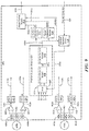
- FIG. 4 is a block diagram showing an illustrative magnetic field sensor proximate to two target object portions, here shown to be separate, that can be like the magnetic field sensor and two portions of FIGS. 1 and 2 , which can generate the signals of FIG. 3 , and which can have a phase difference module operable to identify a phase difference between the signals of FIG. 3 ;
- FIG. 5 is a block diagram showing further details of an illustrative phase difference module according to FIG. 4 ;
- FIG. 6 is a block diagram showing further details of another illustrative phase difference module according to FIG. 4 ;
- FIG. 7 is a block diagram showing further details of another illustrative phase difference module according to FIG. 4 ;
- FIG. 8 is a block diagram showing another illustrative magnetic field sensor proximate to two target object portions, here shown to be separate, that can be like the magnetic field sensor and two portions of FIGS. 1 and 2 , which can generate the signals of FIG. 3 , and which can have a phase difference module operable to identify the phase difference between the signals of FIG. 3 ;
- FIG. 9 is a block diagram showing another illustrative magnetic field sensor proximate to two target object portions, here shown to be separate, that can be like the magnetic field sensor and two portions of FIGS. 1 and 2 , which can generate the signals of FIG. 3 , and which can have a phase difference module operable to identify the phase difference between the signals of FIG. 3 ;
- FIG. 10 is a block diagram of a side view of an illustrative magnetic field sensor that can be like the magnetic field sensor of FIGS. 1 and 2 ;
- FIG. 11 is a graph showing phase shift per period of the first and second signals of FIG. 3 and for different quantities of the target features of FIGS. 1 and 2 ;
- FIG. 12 is a graph showing illustrative signals generated by the first and second one or more magnetic field sensing elements of FIGS. 1 and 2 , and also rising and falling crossing-points that can be used to detect angular position of the target object when the target object rotates;
- FIG. 13 is a graph showing the signals of FIG. 12 , but on a wider time scale
- FIG. 14 is a block diagram showing an illustrative magnetic field sensor proximate to two target object portions, here shown to be separate, that can be like the magnetic field sensor and two portions of FIGS. 1 and 2 , which can generate the signals of FIGS. 10 and 11 , and which can have a crossing detection module and an amplitude difference module to identity an amplitude difference between the upper and lower crossings of the signals of FIGS. 12 and 13 ;
- FIG. 15 is a block diagram showing an illustrative amplitude difference module that can be used as the amplitude difference module of FIG. 14 ;
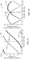
- FIG. 16 is a graph showing a simulated relationship between rising crossing points of the signals of FIGS. 12 and 13 and angle of a target object for different air gaps and for a target object in the form of a gear having teeth (features) with ninety degree edges and in a back-biased arrangement;
- FIG. 17 is a graph showing a simulated relationship between rising crossing points of the signals of FIGS. 12 and 13 and angle of a target object for different air gaps and for a target object in the form of a ring or circular magnet having poles (features);
- FIG. 18 is a graph showing a first derivative of the data (at one air gap) from FIG. 16 in terms of change per period;
- FIG. 19 is a graph showing two simulated relationships like the relationship of FIG. 14 , but for two different pairings of the magnetic field sensing elements of FIGS. 1 and 2 ;
- FIG. 20 is a graph showing two simulated relationships like the relationship of FIG. 18 , but for two different pairings of the magnetic field sensing elements of FIGS. 1 and 2 ;
- FIG. 21 is a block diagram showing another illustrative magnetic field sensor proximate to two target object portions, here shown to be separate, that can be like the magnetic field sensor and two portions of FIGS. 1 and 2 , which can generate the signals of FIGS. 12 and 13 , which can have a crossing detection module and an amplitude difference module to identity an amplitude difference between the upper and lower crossings of the signals of FIGS. 12 and 13 , and which has a position range detection module to switch magnetic field sensing elements according to the graphs if FIGS. 19 and 20 ;
- FIG. 22 is a pictorial showing a perspective view of another magnetic field sensor proximate to a target object, the target object having first and second portions, wherein the first and second portions have different numbers of target features, and wherein the magnetic field sensor has one or more magnetic field sensing elements disposed proximate to a junction between the first portion and second portion;
- FIG. 23 is a pictorial diagram showing a side view of the magnetic field sensor and target object of FIG. 22 ;
- FIG. 24 is a graph showing two signals that can be generated by the magnetic field sensing elements of FIG. 22 ;
- FIG. 25 is a block diagram showing an illustrative magnetic field sensor proximate to two target object portions, here shown to be conjoined, that can be like the magnetic field sensor and two portions of FIGS. 22 and 23 , which can generate the signals of FIG. 24 , and which can have an amplitude detection module operable to identify an amplitude of the signals of FIG. 24 ;
- FIG. 26 is a flow chart showing an illustrative process that can be used by the amplitude detection module of FIG. 25 ;
- FIG. 27 is a block diagram showing another illustrative magnetic field sensor proximate to two target object portions, here shown to be conjoined, that can be like the magnetic field sensor and two portions of FIGS. 22 and 23 , which can generate one of the signals of FIG. 24 , and which can have an amplitude detection module operable to identify an amplitude of one of the signals of FIG. 24 ;
- FIG. 28 is a block diagram of a side view of an illustrative magnetic field sensor that can be like the magnetic field sensor of FIGS. 22 and 23 ;
- FIG. 29 is an isometric drawing of a flat target object having two different portions, each with a different quantity of target features, and first and second substrates of magnetic field sensors according to FIGS. 1 and 2 and FIGS. 22 and 23 , respectively.
- magnetic field sensing element is used to describe a variety of electronic elements that can sense a magnetic field.
- the magnetic field sensing element can be, but is not limited to, a Hall effect element, a magnetoresistance element, or a magnetotransistor.
- Hall effect elements for example, a planar Hall element, a vertical Hall element, and a Circular Vertical Hall (CVH) element.
- magnetoresistance elements for example, a semiconductor magnetoresistance element such as Indium Antimonide (InSb), a giant magnetoresistance (GMR) element, for example, a spin valve, an anisotropic magnetoresistance element (AMR), a tunneling magnetoresistance (TMR) element, and a magnetic tunnel junction (MTJ).
- the magnetic field sensing element may be a single element or, alternatively, may include two or more magnetic field sensing elements arranged in various configurations, e.g., a half bridge or full (Wheatstone) bridge.
- the magnetic field sensing element may be a device made of a type IV semiconductor material such as Silicon (Si) or Germanium (Ge), or a type III-V semiconductor material like Gallium-Arsenide (GaAs) or an Indium compound, e.g., Indium-Antimonide (InSb).
- a type IV semiconductor material such as Silicon (Si) or Germanium (Ge)
- a type III-V semiconductor material like Gallium-Arsenide (GaAs) or an Indium compound, e.g., Indium-Antimonide (InSb).
- some of the above-described magnetic field sensing elements tend to have an axis of maximum sensitivity parallel to a substrate that supports the magnetic field sensing element, and others of the above-described magnetic field sensing elements tend to have an axis of maximum sensitivity perpendicular to a substrate that supports the magnetic field sensing element.
- planar Hall elements tend to have axes of sensitivity perpendicular to a substrate
- metal based or metallic magnetoresistance elements e.g., GMR, TMR, AMR
- vertical Hall elements tend to have axes of sensitivity parallel to a substrate.
- magnetic field sensor is used to describe a circuit that uses a magnetic field sensing element, generally in combination with other circuits.
- Magnetic field sensors are used in a variety of applications, including, but not limited to, an angle sensor that senses an angle of a direction of a magnetic field, a current sensor that senses a magnetic field generated by a current carried by a current-carrying conductor, a magnetic switch that senses the proximity of a ferromagnetic object, a rotation detector that senses passing ferromagnetic articles, for example, magnetic domains of a ring magnet or a ferromagnetic target (e.g., gear teeth) where the magnetic field sensor is used in combination with a back-biased or other magnet, and a magnetic field sensor that senses a magnetic field density of a magnetic field.
- an angle sensor that senses an angle of a direction of a magnetic field
- a current sensor that senses a magnetic field generated by a current carried by a current-carrying conductor
- a magnetic switch that
- parallel and perpendicular are used in various contexts herein. It should be understood that the terms parallel and perpendicular do not require exact perpendicularity or exact parallelism, but instead it is intended that normal manufacturing tolerances apply, which tolerances depend upon the context in which the terms are used. In some instances, the term “substantially” is used to modify the terms “parallel” or “perpendicular.” In general, use of the term “substantially” reflects angles that are beyond manufacturing tolerances, for example, within +/ ⁇ ten degrees.
- processor is used to describe an electronic circuit that performs a function, an operation, or a sequence of operations.
- the function, operation, or sequence of operations can be hard coded into the electronic circuit or soft coded by way of instructions held in a memory device.
- a “processor” can perform the function, operation, or sequence of operations using digital values or using analog signals.
- the “processor” can be embodied in an application specific integrated circuit (ASIC), which can be an analog ASIC or a digital ASIC. In some embodiments, the “processor” can be embodied in a microprocessor with associated program memory. In some embodiments, the “processor” can be embodied in a discrete electronic circuit, which can be analog or digital, and which may or may not have an arithmetic logic unit (ALU).
- ASIC application specific integrated circuit
- ALU arithmetic logic unit
- module can be used to describe a “processor.” However, the term “module” is used more generally to describe any circuit that can transform an input signal into an output signal that is different than the input signal.
- a processor can contain internal processors or internal modules that perform portions of the function, operation, or sequence of operations of the processor.
- a module can contain internal processors or internal modules that perform portions of the function, operation, or sequence of operations of the module.
- a so-called comparator can be comprised of an analog comparator having a two state output signal indicative of an input signal being above or below a threshold level (or indicative of one input signal being above or below another input signal).
- the comparator can also be comprised of a digital circuit having an output signal with at least two states indicative of an input signal being above or below a threshold level (or indicative of one input signal being above or below another input signal), respectively, or a digital value above or below a digital threshold value (or another digital value), respectively.
- the term “predetermined,” when referring to a value or signal, is used to refer to a value or signal that is set, or fixed, in the factory at the time of manufacture, or by external means, e.g., programming, thereafter.
- the term “determined,” when referring to a value or signal, is used to refer to a value or signal that is identified by a circuit during operation, after manufacture.
- amplifier is used to describe a circuit element with a gain greater than one, less than one, or equal to one.
- line and “linear” are used to describe either a straight line or a curved line.
- the line can be described by a function having any order less than infinite.
- planar Hall effect elements are shown in some figures herein, in other embodiments, any type of magnetic field sensing elements can be used.
- absolute position and “absolute angle” are used to refer to a position or an angle of a target object relative of a reference position determined by a position of a magnetic field sensor.
- a magnetic field sensor 102 can sense an absolute position (i.e., absolute rotation angle) of a target object 106 .
- the target object 106 has a first portion 106 a having a first quantity of target features, e.g., target features 106 aa , 106 ab , and a second portion 106 b having a second quantity of target features, e.g., target features 106 ba , 106 bb , different than the first quantity.
- the first and second portions 106 a , 106 b can be mechanically fixed together.
- the target object 106 including the first and second portions 106 a , 106 b , is capable of a movement relative to the magnetic field sensor 102 .
- the magnetic field sensor 102 can include a first one or more magnetic field sensing elements 104 a disposed proximate to the first portion 106 a .
- the first one or more magnetic field sensing elements 104 a can be operable to generate a first magnetic field signal responsive to the movement (e.g., rotation) of the first portion 106 a .
- the magnetic field sensor 102 can also include a second one or more magnetic field sensing elements 104 b disposed proximate to the second portion 106 b .
- the second one or more magnetic field sensing elements 104 b can be operable to generate a second magnetic field signal responsive to the movement of the second portion 106 b .
- the magnetic field sensor 102 can also include a position detection module coupled to use the first and second magnetic field signals to generate a position value indicative of the absolute position, and an output format module coupled to receive the position value and to generate an output signal from the magnetic field sensor indicative of the absolute position.
- a position detection module coupled to use the first and second magnetic field signals to generate a position value indicative of the absolute position
- an output format module coupled to receive the position value and to generate an output signal from the magnetic field sensor indicative of the absolute position.
- Examples described herein use target objects for which the quantities of features on the first and second portions of the target object differ by one feature.
- the difference can be greater, for example, one, two, three, four, five, or more than five features.
- Embodiments described herein use target objects having first and second target object portions that rotate or move in the same direction.
- some of the target features are teeth of a respective ferromagnetic gear portion and other target features, e.g., 106 ab , 106 bb , are valleys.
- These embodiments can include a permanent magnet (see, e.g., FIG. 10 ) disposed within or proximate to the magnetic field sensor 102 in a so-called “back-biased” arrangement. In a back-biased arrangement, the magnetic field sensor 102 experiences changes of magnetic field generated by the permanent magnet as the gear teeth and valleys pass by the magnetic field sensor 102 .
- some of the target features, e.g., 106 aa , 106 ba are north magnetic poles of a respective ring magnet portion and other target features, e.g., 106 ab , 106 bb , are south magnetic poles. These embodiments have no back-biased magnet.
- the magnetic field sensor 102 is again shown proximate to the target object 106 .
- the first one or more magnetic field sensing elements 104 a can include three magnetic field sensing elements S 1 , S 2 , S 3
- the second one or more magnetic field sensing elements 104 b can include three magnetic field sensing elements S 4 , S 5 , S 6 .
- a graph 300 has a horizontal axis with a scale in units of time in arbitrary units and a vertical axis with a scale in units of differential magnetic field in arbitrary units.
- the differential field can be identified by a difference of signals from the magnetic field sensing elements S 1 , S 2 , S 3 of FIG. 2 and a difference of signals from the magnetic field sensing elements S 4 , S 4 , S 6 of FIG. 2 .
- differential arrangements are not used and the magnetic field sensor can use only two of the magnetic field sensing elements S 1 , S 2 , or S 3 and S 4 , S 5 , or S 6 , taken individually.
- a signal 302 is indicative of the difference of signals from the magnetic field sensing elements S 1 , S 2 , S 3 of FIG. 2 and a signal 304 is indicative of the difference of signals from the magnetic field sensing elements S 4 , S 5 , S 6 of FIG. 2 as the target object 106 spins or rotates.
- signal 302 can be indicative of a difference S 1 -S 2 and signal 304 can be indicative of a difference S 4 -S 5 .
- other differences are possible.
- the signals 302 , 304 can have a phase difference that changes with rotation of the target object.
- the phase difference of the signals 302 , 304 can be determined in a variety of ways.
- the phase difference can be determined using a threshold value 306 and comparing the first and second signal 302 , 304 to the threshold value 306 .
- Differences of times when the first signal 302 and the second signal 304 cross the threshold value 306 are identified as a shift(1) and a shift(2), each of which, in time (e.g., as a percentage of a period of one of the signals 302 , 304 ), is indicative of a phase difference between the first and second signals 302 , 304 , wherein the phase difference changes with cycle of the first and second signals 302 , 304 .
- Period1 and Period2 are different periods.
- an illustrative magnetic field sensor 400 can be disposed proximate to a first portion 404 a of a target object and a second portion 404 b of a target object.
- the first and second portions 404 a , 404 b of the target object can be the same as or similar to the first and second portions 106 a , 106 b of the target object 106 of FIGS. 1 and 2 . While the first and second portions 404 a , 404 b shown to be separate, it should be understood that the first and second portions 404 a , 404 b are shown as being mechanically separate merely for clarity in reference to the magnetic field sensor 400 .
- the magnetic field sensor 400 can include a first one or more magnetic field sensing elements 406 a , 406 b , 406 c disposed proximate to the first portion 404 a of the target object.
- the magnetic field sensor 400 can also include a second one or more magnetic field sensing elements 440 a , 440 b , 440 c disposed proximate to the second portion 404 b of the target object.
- the first one or more magnetic field sensing elements 406 a , 406 b , 406 c can be the same as or similar to the first one or more magnetic field sensing elements 104 a of FIGS. 1 and 2 .
- the second one or more magnetic field sensing elements 440 a , 440 b , 440 c can be the same as or similar to the second one or more magnetic field sensing elements 104 b of FIGS. 1 and 2 .
- Magnetic field sensing elements 406 a , 406 c can be coupled in a differential arrangement to input nodes of an amplifier 408 to generate an amplified signal 408 a.
- An automatic gain control and automatic offset control circuit 410 can be coupled to the amplified signal 408 a and can generate a controlled signal 410 a , also indicated with a designation A.
- a threshold generator circuit 416 can be coupled to the controlled signal 410 a and can generate a threshold signal 416 a.
- the controlled signal 410 a and the threshold signal 416 a can be coupled to input nodes of comparator 412 to generate a comparison signal 412 a , also indicated with a designation A′.
- the comparison signal 412 a is a two state signal with high states and low states.
- the comparison signal 412 a can also be referred to as a speed signal for which a rate of transitions is indicative of a speed of rotation of the first and second portions 404 a , 404 b of the target object.
- the threshold generator 416 can be operable to identify one or more threshold values between a positive peak and a negative peak of the controlled signal 410 a .
- the threshold generator 416 can sequentially identify a first threshold value that is about sixty percent of a range between the positive peak and the negative peak of the controlled signal 410 a , and a second threshold value that is about forty percent of the range between the positive peak and the negative peak of the controlled signal 410 a .
- the comparison signal 412 a can have transitions of state when the controlled signal 410 a crosses upward past the first threshold value and crosses downward past the second threshold value, back and forth.
- Magnetic field sensing elements 406 b , 406 c can be coupled in another differential arrangement to input nodes of an amplifier 422 to generate an amplified signal 422 a.
- the amplified signal 408 a and the amplified signal 422 a can both have characteristics comparable to the signal 302 of FIG. 3 .
- An automatic gain control and automatic offset control circuit 424 can be coupled to the amplified signal 422 a and can generate a controlled signal 424 a , also indicated with a designation B.
- a threshold generator circuit 428 can be coupled to the controlled signal 424 a and can generate a threshold signal 428 a.
- the controlled signal 424 a and the threshold signal 428 a can be coupled to input nodes of a comparator 426 to generate a comparison signal 426 a , also indicated with a designation B′.
- the comparison signal 426 a is a two state signal with high states and low states.
- Magnetic field sensing elements 440 a , 440 c can be coupled in a differential arrangement to input nodes of an amplifier 442 to generate an amplified signal 442 a .
- An automatic gain control and automatic offset control circuit 446 can be coupled to the amplified signal 442 a and can generate a controlled signal 446 a , also indicated with a designation C.
- a threshold generator circuit 450 can be coupled to the controlled signal 446 a and can generate a threshold signal 450 a.
- the controlled signal 446 a and the threshold signal 450 a can be coupled to input nodes of comparator 448 to generate a comparison signal 448 a , also indicated with a designation C′.
- the comparison signal 448 a is a two state signal with high states and low states.
- Magnetic field sensing elements 440 b , 440 c can be coupled in another differential arrangement to input nodes of an amplifier 452 to generate an amplified signal 452 a.
- the amplified signal 442 a and the amplified signal 452 a can both have characteristics comparable to the signal 304 of FIG. 3 , having a time/phase shift relative to the signals 408 a , 422 a that changes with rotation angle of the target object.
- An automatic gain control and automatic offset control circuit 454 can be coupled to the amplified signal 452 a and can generate a controlled signal 454 a , also indicated with a designation D.
- a threshold generator circuit 458 can be coupled to the controlled signal 454 a and can generate a threshold signal 458 a.
- the controlled signal 454 a and the threshold signal 458 a can be coupled to input nodes of a comparator 456 to generate a comparison signal 456 a , also indicated with a designation D′.
- the comparison signal 456 a is a two state signal with high states and low states.
- the magnetic field sensor 400 can also include a position detection module 428 .
- the position detection module 428 can include a 4:2 multiplexer 430 coupled to the signals A and B (or alternatively, the signals A′ and B′).
- the 4:2 multiplexer 430 can also be coupled to the signals C and D (or alternatively, the signals C′ and D′).
- the 4:2 multiplexer 430 is operable to generate two signals 430 a , 430 b in one or more of the following combinations:
- the two signals 430 a , 430 b can be selected in accordance with a multiplexer control signal 436 a.
- the two signals 430 a , 430 b are coupled to a phase difference module 432 operable to identify a phase difference between the two signals 430 a , 430 b and operable to generate a phase difference signal 432 a .
- Circuits described in figures below describe arrangements that can be used as the phase difference module 432 .
- a position decoder module 434 can be coupled to the phase difference signal 432 a and can generate a position signal 434 a indicative of a position (e.g., a rotation angle) of the target object 404 a , 404 b .
- the position decoder module 434 can be a non-volatile memory device that can act as a decoder between the phase difference signal 432 a and the position signal 434 a.
- An element selection circuit 436 can be coupled to an element selection signal 438 from outside of the magnetic field sensor 400 and can be operable to generate the multiplexer control signal 436 a to control which ones of the above-listed signals are used.
- An output format module 420 can be coupled to one or more of the position signal 434 a , the speed signal 412 a , or the direction signal 418 a .
- the output format module 420 can be operable to generate a formatted output signal 420 a indicative of one or more of a position, a speed, or a direction of movement of the portions 404 a , 404 b of the target object.
- the formatted output signal 420 a can be in any one of a variety of formats, including, but not limited to, SPI (serial peripheral interface), PWM (pulse width modulation), I2C, and SENT (Single Edge Nibble Transmission).
- SPI serial peripheral interface
- PWM pulse width modulation
- I2C I2C
- SENT Single Edge Nibble Transmission
- position information carried by the formatted signal 420 a is present only during a time period proximate to a power up of the magnetic field sensor. In other embodiments, position information carried by the formatted signal 420 a is present only during a time period proximate to first movement of the portions 404 a , 404 b of the target object after they have stopped. Thereafter, the formatted signal can be indicative of only one or more of the speed or the direction of movement of the portions 404 a , 404 b of the target object.
- a phase difference between the above-listed two signals 430 a , 430 b is indicative of an absolute rotation angle of the target object 404 a , 404 b.
- some of the elements of the magnetic field sensor 400 can be omitted.
- there is no selection of the two signals 430 a , 430 b and instead, the two signal 430 a , 430 b are predetermined and hard wired, in which case, the 4:2 multiplexer 430 , the element selection circuit 436 , and circuits that generate unused ones of the signals A, B, C, D, A′, B′, C′, D′ can be omitted.
- the AGC/AOA circuits 410 , 424 , 446 , 454 can be omitted and similar functions can instead be embedded within other modules, for example, within the phase difference module 432 .
- the first one or more magnetic field sensing elements 406 a , 406 b , 406 c can consist of only two magnetic field sensing elements 406 a , 406 b and the second one or more magnetic field sensing elements 440 a , 440 b , 440 c can consist of only two magnetic field sensing elements 440 a , 440 b .
- the first one or more magnetic field sensing elements 406 a , 406 b , 406 c can consist of only one magnetic field sensing element 406 a and the second one or more magnetic field sensing elements 440 a , 440 b , 440 c can consist of only one magnetic field sensing element 440 a.
- an illustrative phase difference module 500 can be the same as or similar to the phase difference module 432 of FIG. 4 . It will be understood that a phase difference between two signals can be determined by a time difference between the two signals.
- the phase difference module can be coupled to the two signals 430 a , 430 b of FIG. 4 , which can be any of the two signals listed above.
- phase difference module 500 can be coupled to the signals A or B and the signals C or D of FIG. 4 .
- a threshold generator 504 can identify a threshold associated with the signal A or B and can generate a threshold signal 504 a .
- a threshold generator 512 can identify a threshold associated with the signal C or D and can generate a threshold signal 512 a .
- the threshold generators 504 , 512 are operable to identify single thresholds, for example, at eighty, seventy, sixty, or fifty percent of as peak-to-peak range of respective input signals A, B, C, or D.
- a comparator 502 can be coupled to the signal A or B and the threshold signal 504 a and can generate a two-state comparison signal 502 a .
- a comparator 510 can be coupled to the signal C or D and the threshold signal 512 a and can generate a two-state comparison signal 510 a.
- a start/stop counter 506 can be coupled to the comparison signal 502 a at a start input node and can be coupled to receive the comparison signal 510 a at a stop input node, both nodes responsive to predetermined direction of state transitions.
- the start/stop counter 506 can generate a count signal 506 a received at latches 508 operable to temporarily store the count signal 506 a to generate a latched count signal 508 a.
- An oscillator 514 can generate a clock signal 514 a received at a clock input node of the start/stop counter 506 .
- a time delay circuit 516 can be coupled to the comparison signal 510 a and can generate a time delayed signal coupled to a reset input node of the start/stop counter 506 to reset the start/stop counter 506 shortly after the start/stop counter 506 is stopped by the comparison signal 510 a.
- the latches 508 a can be latched upon a state of the comparison signal 510 a being received at a latch input node of the latches 508 a.
- Count values from the latches 508 are indicative of a phase between the two signals A or B and C or D, in arbitrary units.
- the signals A or B and C or D are not received by the phase difference module 500 .
- the signals A′ or B′ and C′ or D′ of FIG. 4 are received by the phase difference module 500 .
- the signals A′, B′, C′, and D′ are already two-state signals.
- the signal A′ or B′ can be received at the start node of the start/stop counter 506 instead of the comparison signal 502 a .
- the signal C′ or D′ can be received at the stop node of the start/stop counter 506 instead of the comparison signal 502 a.
- the phase difference module 500 determines a phase difference between two signals by measuring a time difference between the two signals. Essentially, the phase difference module 500 can identify time differences between points on the signals 302 , 304 of FIG. 3 where they cross the threshold value 306 . Embodiments described in conjunction with FIGS. 6 and 7 use other circuits to determine a phase difference between two signals.
- phase difference module 600 can be the same as or similar to the phase difference module 432 of FIG. 4 .
- the phase difference module 600 can include a correlation module 602 coupled to the signals A or B and the signals C or D of FIG. 4 . Correlation is a technique that can identify a phase difference between two signals. Thus, the correlation module 602 can generate a phase signal 602 a.
- phase difference module 700 can be the same as or similar to the phase difference module 432 of FIG. 4 .
- the phase difference module 700 can include a phase locked loop (PLL) module 702 coupled to the signals A or B and the signals C or D of FIG. 4 .
- a phase locked loop can identify a phase difference between two signals.
- the correlation module 702 can generate a phase signal 702 a.
- a magnetic field sensor 800 can be disposed proximate to the first and second portions 404 a , 404 b of the target object.
- the magnetic field sensor 800 is a reduced version of the magnetic field sensor 400 of FIG. 4 , and operates in substantially the same way.
- a magnetic field sensing element 804 can be operable to generate a magnetic field signal 804 a coupled to an amplifier 806 .
- the amplifier 806 can be operable to generate an amplified signal 806 a.
- An AGC/AOA module 808 can be coupled to the amplified signal 806 a and can generate a controlled signal 808 a , also indicated with a designation A.
- a threshold generator 812 can be coupled to the controlled signal 808 a and can generate a threshold signal 812 a.
- the controlled signal 808 a and the threshold signal 812 a can be coupled to input nodes of comparator 810 to generate a comparison signal 810 a , also indicated with a designation A′.
- the comparison signal 810 a is a two state signal with high states and low states.
- the comparison signal 810 a can also be referred to as a speed signal for which a rate of transitions is indicative of a speed of rotation of the first and second portions 404 a , 404 b of the target object.
- a magnetic field sensing element 816 can be operable to generate a magnetic field signal 816 a coupled to an amplifier 818 .
- the amplifier 818 can be operable to generate an amplified signal 818 a.
- An AGC/AOA module 820 can be coupled to the amplified signal 8018 a and can generate a controlled signal 820 a , also indicated with a designation C
- a threshold generator 824 can be coupled to the controlled signal 820 a a and can generate a threshold signal 812 a.
- the controlled signal 820 a and the threshold signal 824 a can be coupled to input nodes of comparator 822 to generate a comparison signal 822 a , also indicated with a designation C′.
- the comparison signal 822 a is a two state signal with high states and low states.
- a phase difference module 828 can be coupled to the signals A and C or A′ and C′.
- the phase difference module can be the same as or similar to the phase difference module 432 of FIG. 4 . Because the signals A or C and A′ or C′ can be statically coupled to the phase difference module 828 , the phase difference module need not be preceded by the multiplexer 430 of FIG. 4 . However, in other embodiments, a multiplexer can be added to selected between the signals A or A′ and C or C′.
- the phase difference module can be operable to generate a phase signal 432 a indicative of a phase difference between the signals A or A′ and C or C′.
- a position decoder module 830 can be coupled to the phase signal 828 a a and can decode the phase signal 828 a to produce position signal 830 a similar to the position signal 432 a of FIG. 4 .
- magnetic field sensor 900 can employ other techniques to generate the speed and direction signals of FIG. 4 .
- the magnetic field sensor 900 can have a position detection module that can be similar to the position detection module of FIG. 4 , and that can generate a position signal 930 a similar to the positions signal 434 a of FIG. 4 indicative of a position (e.g., angle) of the portions 404 a , 404 b of the target object.
- a position signal 930 a Similar to the positions signal 434 a of FIG. 4 indicative of a position (e.g., angle) of the portions 404 a , 404 b of the target object.
- both speed of movement and direction of the movement of the portions 404 a , 404 b of the target object can be calculated.
- some of the circuits of FIG. 4 can be omitted as shown in FIG. 9 .
- a speed detection module 934 can be coupled to the position signal 930 a and can generate a speed signal 934 a indicative of a speed or rate of movement of the portions 4040 a , 404 b of the target object.
- a direction detection module 932 can be coupled to the position signal 930 a and can generate a direction signal 932 a indicative of a direction of the movement of the portions 4040 a , 404 b of the target object.
- An element selection module 936 and multiplexer control signal 936 a can be similar to the element selection module 436 and multiplexer control signal 436 a of FIG. 4 .
- An output format module 920 and formatted signal 920 a can be the same as or similar to the output format module and formatted signal 420 a of FIG. 4 .
- a magnetic field sensor 1000 can be illustrative of a mechanical arrangement of any of the magnetic field sensors of figures above.
- the magnetic field sensor 1000 can include a first semiconductor substrate 1002 upon which can be disposed the first one or more magnetic field sensing elements 406 a , 406 b , 406 c of FIG. 4 of 804 of FIG. 8 .
- the magnetic field sensor 1000 can also include a second semiconductor substrate 1004 upon which can be disposed the second one or more magnetic field sensing elements 440 a , 440 b , 440 c of FIG. 4 or 816 of FIG. 8 .
- the groups of magnetic field sensing elements can be more widely separated than would otherwise be possible if all of the magnetic field sensing elements were disposed on a single semiconductor substrate.
- other elements of the magnetic field sensor 400 of FIG. 4 or 800 of FIG. 8 can be disbursed among the first and second semiconductor substrates. However, in another embodiment, some of the other elements can be disposed upon an optional third semiconductor substrate 1006 .
- the semiconductor substrates 1002 , 1004 , 1006 can be coupled to a base substrate 1008 , which can be comprised of a semiconductor or insulator (e.g., ceramic) material.
- the coupling to the base substrate can be made by solder balls, e.g., 1010 , or the like.
- Interconnecting traces upon the base substrate 1008 can make interconnections between the semiconductor substrates 1002 , 1004 , 1006 .
- the base substrate 1008 can be coupled to a base plate 1012 a of a lead frame 1012 with couplings, e.g., 1014 , to make connection to leads, e.g., 1012 b , of the lead frame 1012 .
- the leads, e.g., 1012 b can be formed into a surface mount configuration.
- a permanent magnet 1016 can be disposed proximate to the substrates 1002 , 1004 , 1006 . In other embodiments used to sense a ring magnet, the permanent magnet 1016 can be omitted.
- a solid molded enclosure 1018 can surround parts of the magnetic field sensor 1000 as shown.
- the magnetic field sensors described above are disposed entirely upon one substrate.
- a graph 1100 has a horizontal axis with a scale in units of rotation speed of the portions 404 a , 404 b of the target object of FIG. 4 in unit of revolutions per minute.
- the graph 1100 has a vertical axis with a scale in units of time shift per period in units of seconds.
- the time shift is essentially the shift identified in FIG. 3 , where the shift changes with each cycle of the signals 302 , 304 .
- a line 1102 is indicative of one of the portions, e.g., 404 a of FIG. 4 , of the target object having twenty teeth and the other portion having twenty-one teeth.
- a line 1104 is indicative of one of the portions, e.g., 404 a of FIG. 4 , of the target object having one hundred teeth and the other portion having one hundred one teeth.
- Other lines on the graph 1100 are at intervals of twenty teeth.
- the shift per period is less for higher rotation speeds. Also, the shift per period is less for target objects with greater numbers of teeth (or poles).
- a time resolution of the magnetic field sensor can limit the maximum allowable rotation speed at which absolute angles can be reliably determined.
- the graph 1100 serves to predict the maximum allowable rotation speed for a number of target combinations. For example, from the graph 1100 , for a magnetic field sensor that can resolve time shifts greater than or equal to one hundred microseconds, assuming a pair of targets with twenty and twenty one features (line 1102 ), the maximum target speed would be approximately two thousand revolutions per minute.
- a graph 1200 has a horizontal axis with a scale in units of absolute angle of the target object 106 of FIG. 1 , having two target object portions, in units of degrees, and a vertical axis with a scale in units of differential magnetic field in normalized arbitrary units related to that which would be experienced by two magnetic field sensing elements taken differentially.
- the differential field can be identified by a difference of signals from the magnetic field sensing elements S 1 , S 2 , S 3 of FIG. 2 , e.g., S 1 -S 2 , which is like signal 1202 , and a difference of signals from the magnetic field sensing elements S 4 , S 5 , S 6 of FIG. 2 , e.g., S 4 -S 5 , which is like the signal 1204 .
- the graph 1200 shows first and second signals 1202 , 1204 that are similar to the signals 302 , 304 of FIG. 3 .
- the absolute angle of the horizontal axis is similar to the time on the horizontal axis of FIG. 3 .
- the signals 1202 , 1204 are not compared to a threshold (e.g., 306 of FIG. 3 ), but instead, proximate (in time) crossings (e.g., 1206 , 1208 , respectively) of the first and second signals 1202 , 1204 are identified.
- the magnetic field sensor can distinguish between crossings at which the slope of signal 1204 is positive and crossings at which the slope of signal 1204 is negative at the time of each crossing. Magnetic field sensors described below in conjunction with FIGS. 14 and 21 use this behavior. Magnetic field sensors described herein can use one, the other, or both the crossings at the positive slope of the signals 1204 and crossings at the negative slope of the signal 1204 .
- a graph 1300 has the same axes as those of the graph 1200 of FIG. 12 .
- the horizontal axis has a wider angle scale.
- Points 1302 are indicative of signal crossings for which the slope of signal 1204 is positive, while points 1304 are indicative of signal crossings for which the slope of signal 1204 is negative. These points are like those of FIG. 12 , but are visible throughout a range of angular rotations of the target object 106 of FIGS. 1 and 2 . It should be apparent that some embodiments can use either the crossings 1302 at the positive slope of the signal 1204 or crossings 1304 at the negative slope of the signal 1204 . Either can uniquely identify the absolute angle.
- FIG. 12 Other embodiments can use a difference between proximate crossings, e.g. points 1206 , 1208 of FIG. 12 , in order to determine the absolute position of the target. In this case, it is both the difference between proximate crossings and the sign of the difference that are indicative of the angle of rotation. It should be apparent that these embodiments can use both the crossings at the positive slope of the signal 1204 and crossings at the negative slope of the signal 1204 .
- FIG. 14 in which like elements of FIG. 4 have like reference designations, the position detection mode 428 of FIG. 4 is replaced by a position detection module 1402 that makes use of the signal crossing difference of FIGS. 12 and 13 .
- the position detection module can include a 4:2 multiplexer 1404 similar to the 4:2 multiplexer 430 of FIG. 4 . However, only the signal A or B and C or D are received by and used by the 4:2 multiplexer 1404 .
- the 4:2 multiplexer 1404 can select and generate two signals (see, e.g., signal 1202 , 1204 of FIG. 12 ) from the group of two signals:
- the selection is determined in accordance with a multiplexer control signal 436 a.
- the selected two signals can be coupled to a crossing detection module 1406 operable to detect some of or all of the crossings of the two signals received by the crossing detection module.
- a crossing detection module 1406 operable to detect some of or all of the crossings of the two signals received by the crossing detection module.
- An illustrative crossing detection module is described below in conjunction with FIG. 15 .
- the crossing detection module 1406 can be operable to generate a crossing signal 1406 a indicative of the detected crossings of the two signals.
- an amplitude difference module 1408 can identify a difference of amplitudes between proximate crossings of the crossing signal 1406 a .
- the amplitude difference module 1408 can generate a difference signal 1408 a indicative of the difference of amplitudes, which, as identified in conjunction with FIGS. 12 and 13 , is indicative of an angle of rotation of the first and second portions 404 a , 404 b of the target object.
- a position decoder module 1210 can be coupled to the crossing signal 1406 a (or optionally, to the difference signal 1408 a ) and can be operable to generate a position signal 1410 a indicative of a position (e.g., angular position) of the target object.
- Output format module 420 can generate a formatted signal that can be the same as or similar to the formatted signal 420 a of FIG. 4 .
- an illustrative crossing detection module 1500 can include a comparator 1502 to generate a crossing signal 1502 a indicative of crossings of the signals A or B and C or D.
- the crossing signal 1502 a can be the same as or similar to the crossing signal 1406 a of FIG. 14 .
- graphs 1600 and 1700 each include a horizontal axis with a scale in units of rotation angle of the portions 404 a , 404 b of the target object of FIG. 14 in degrees and each include a vertical axis with a scale in units of normalized differential magnetic field at which crossing points of two signals occur (e.g., points 1304 in FIG. 13 ).
- Points 1602 are indicative of only one set of crossings of the signals 1202 and 1204 of FIG. 12 , e.g., crossings 1304 of FIG. 13 .
- the other set of crossings, e.g., 1302 of FIG. 13 is omitted for clarity.
- a first signal is generated by a difference of signals from the magnetic field sensing elements S 1 , S 2 , S 3 of FIG. 2 , e.g., S 1 -S 2 , which is like signal 1202
- a second signal crossing the first signal is generated by a difference of signals from the magnetic field sensing elements S 4 , S 5 , S 6 of FIG. 2 , e.g., S 4 -S 5 .
- a plurality of curves 1602 on the graph 1600 is indicative of a back-biased arrangement for sensing rotation of a ferromagnetic gear having teeth with ninety degree corners, for different air gaps between the magnetic field sensor 1400 of FIG. 14 and the target object, the air gaps spanning between 0.5 mm and 3.0 mm in increments of 0.5 mm.
- the data in FIG. 16 were simulated assuming a pair of targets with sixty and sixty-one teeth.
- a plurality of curves 1702 on the graph 1700 is indicative of a non back-biased arrangement for sensing rotation of a ring or circular magnet having north and south poles around a circumference of the ring or circular magnet, for different air gaps between the magnetic field sensor 1400 of FIG. 14 and the target object, the air gaps spanning between 0.5 mm and 3.0 mm in increments of 0.5 mm.
- the data in FIG. 16 were simulated assuming a pair of ring-magnet targets with sixty and sixty-one pole pairs.
- An illustrative installed unit-to-unit tolerance for the air gap is about +/ ⁇ 0.5 mm.
- a graph 1800 has a horizontal axis with a scale in units of rotation angle in degrees of the portions 404 a , 404 b of the target object described above in conjunction with FIG. 14 .
- the graph 1800 also has a vertical axis with a scale in units of crossing point change per tooth-valley period for one set of crossings, e.g., crossings 1304 of FIG. 13 .
- Points 1802 are indicative of rates of change of the one set of crossings of the two signals 1202 , 1204 of FIG. 12 , e.g., crossings 1304 of FIG. 13 .
- a crossing point change per period of curve 1304 is highest near one hundred eighty degrees of rotation of the target object and lowest for rotation angles near zero and three hundred sixty degrees of rotation.
- a limiting factor for accurate determination of the absolute angle in this embodiment is the capability of the magnetic field sensor to resolve the differential field at which each crossing point occurs. This is the most difficult for rotation angles near zero and three hundred sixty degrees of rotation, where the crossing point change per period is small, as shown in FIG. 18 .
- a graph 1900 which is like the graph 1600 of FIG. 16 , includes a horizontal axis with a scale in units of rotation angle of the portions 404 a , 404 b of the target object of FIG. 14 in degrees, and a vertical axis with a scale in units of differential magnetic field crossing points (see FIG. 16 for an explanation of the vertical axis).
- relatively high sensitivity can be maintained at all rotation angles if a strategy is adopted using different pairs of sensing elements in FIG. 2 at different rotation angles of the target object, e.g. S 3 -S 2 crossing S 5 -S 4 ( 1902 a and 1902 b ) at some rotation angles, and, S 2 -S 1 crossing S 6 -S 5 ( 1904 a and 1904 b ) at other rotation angles.
- This strategy of using offset pairs of sensing elements shifts the absolute angle at which the maximum slope of the simulated data in FIG. 19 occurs away from one hundred eighty degrees when compared to the simulations in FIGS. 16-17 .
- FIG. 20 is similar to FIG. 18 .
- a set of crossing point changes per tooth-valley period 2002 shows slopes of the set of points 1902 a , 1902 b of FIG. 19 .
- a set of crossing point changes per second 2004 shows slopes of the set of points 1904 a , 1904 b of FIG. 19 .
- the set of points 2002 can be used according to crossings generated by S 3 -S 2 crossing S 5 -S 4 (see FIGS. 1 and 2 ), and for angles of the target object between about one hundred eighty degrees and three hundred sixty degrees, the set of points 2004 can be used according to crossings generated by S 2 -S 1 crossing S 6 -S 5 .
- a magnetic field sensor 2100 is like the magnetic field sensor 1400 of FIG. 14 , except that the element selection circuit 436 of FIG. 14 is replaced by a position range detection circuit 2102 that can generate a multiplexer control signal 2102 a that can change connections of the 4:2 multiplexer 1404 during a rotation of the portions 404 a , 404 b of the target object.
- the magnetic field sensor 2100 can control the 4:2 multiplexer 1404 to use signals A and C during a first selected one hundred eighty degrees of rotation of the target object and to use signals B and D during a second selected one hundred eighty degrees of rotation of the target object.
- Other signal combinations are also possible.
- the position decoder module 1410 of FIG. 14 can also be replaced by a position decoder module 2101 that can account for the phase shift of the crossing signals depicted in FIGS. 19 and 20 in accordance with different signals selected by the 4:2 multiplexer 1404 .
- a magnetic field sensor 2204 can sense an absolute position of a target object 2202 .
- the target object 2202 has a first portion 2202 a having a first quantity of target features and a second portion 2202 b having a second quantity of target features different than the first quantity.
- the first and second portions 2202 a , 2202 b are proximate and mechanically fixed together.
- the target object 2202 including the first and second portions 2202 a , 2202 b , is capable of a movement (e.g., a rotation).
- the magnetic field sensor 2204 can include one or more magnetic field sensing elements disposed proximate to a mechanical intersection 2202 c to sense both the first and second portions 2202 a , 2202 b of the target object 2202 with the same one or more magnetic field sensing elements.
- the one or more magnetic field sensing elements are operable to generate a first magnetic field signal responsive to the movement of both the first and second portions 2202 a , 2202 b .
- the magnetic field sensor 2202 can include a position detection module operable to use the first magnetic field signal to generate a position signal (i.e., values) indicative of the absolute position and an output format module coupled to receive the position value and to generate an output signal from the magnetic field sensor indicative of the absolute position.
- the magnetic field sensor 2204 is disposed at a different position relative to a target object 2202 than that shown in FIGS. 1 and 2 .
- the target object 2202 can be the same as or similar to the target object 106 of FIGS. 1 and 2 .
- the magnetic field sensor 2204 is disposed proximate to the junction 2202 c between first and second portions 2202 a , 220 b of the target object 2202 .
- the magnetic field sensor 2204 is disposed proximate to a junction 2202 c between first and second portions 2202 a , 2200 b of the target object 2202 .
- valleys of the first portion 2202 a of the target object 2202 are proximate to valleys of the second portion 2202 b
- valleys of the first portion 2202 a are proximate to teeth of the second portion 2202 b.
- the magnetic field sensor 2204 can experience influence from the first and second portions 2202 a , 2202 b together at the same time.
- target object 2202 is shown as a gear having teeth and valleys, in other embodiments, a ring or circular magnet can be used with alternating north and south poles around its circumference.
- a graph 2400 has a horizontal axis with a scale in units of rotation angle of the target object 2202 of FIGS. 22 and 23 .
- the graph 2400 also has a vertical axis with a scale in units of differential magnetic field in Gauss experienced by the magnetic field sensor 2204 of FIGS. 1 and 2 .
- the graph 2400 has two signals 2402 , 2404 .
- the two signals are signals generated within the magnetic field sensor 2204 as the target object rotates. At some rotations of the target object the magnetic field sensor 2204 is proximate to like features of the two portions 2202 a , 2202 b of the target object 2200 , e.g., teeth to north poles. At other rotations, the magnetic field sensor is proximate to opposing features, e.g., a tooth and a valley or a north pole and south pole. An amplitude of one of or both of the signals 2402 , 2404 can be detected by a magnetic field sensor 25 described below.
- a magnetic field sensor 2500 can be disposed proximate to the target object 2202 of FIGS. 22 and 23 .
- the magnetic field senor 2500 can generate the amplified signals 408 a , 422 a of FIG. 4 , also identified as A′′ and B′′, similar to signals A and B of FIG. 4 .
- the signals A′′ and B′′ can be received by the speed/direction module 414 of FIG. 4 to generate the speed signal 412 a and the direction signal 418 a of FIG. 4 .
- a maximum peak-to-peak detection module 2502 can receive the amplified signal 408 a and can identify and generate a maximum peak-to-peak value 2502 a of the amplified signal 408 a determined as the target object 2200 rotates.
- a non-volatile memory 2504 can store the maximum peak-to-peak value 2502 a .
- the non-volatile memory 2504 is operable to provide a stored maximum peak-to-peak value 2504 a , also identified as a signal E.
- a maximum peak-to-peak detection module 2506 can receive the amplified signal 422 a and can identify and generate a maximum peak-to-peak value 2506 a of the amplified signal 422 a determined as the target object 2200 rotates.
- a non-volatile memory 2508 e.g., an EEPROM, can store the maximum peak-to-peak value 2506 a .
- the non-volatile memory 2508 is operable to provide a stored maximum peak-to-peak value 2508 a , also identified as a signal F.
- a position detection module 2510 can include an amplitude detection module 2512 coupled to at least one of the signal A′′ or the signal B′′ and coupled to at least one of the stored maximum peak-to-peak values E or F.
- the amplitude detection module 2512 can be operable to identify a relative amplitude of at least one of the signal A′′ or the signal B′′ in view of at least one of the stored maximum peak-to-peak values E or F.
- the relative amplitude can be indicative of a rotation angle of the target object. See also FIG. 24 .
- the amplitude detection module 2512 can be operable to generate an amplitude signal 2512 a (i.e., one or more amplitude values) indicative of the rotation angle.
- a position decoder module 2514 can be coupled to the amplitude signal 2512 a and can be operable to generate a position signal 2514 a (i.e., position values) indicative of the rotation angle.
- An output format module can be coupled to at least one of the position signal 2514 a , the speed signal 412 a , or the direction signal 418 a and can be operable to generate an output signal 2516 a indicative of at least one of the speed of rotation, the direction of rotation, and the absolute rotation angle of the target object.
- Characteristics of the output signal 2516 a can be the same as or similar to characteristics of the output signal 420 a of FIG. 4 described above.
- the nonvolatile memory 2504 can be coupled to a “set E” signal 2518 to set the maximum peak-to-peak value stored in the non-volatile memory 2504 to an initial value at start up.
- the nonvolatile memory 2508 can be coupled to a “set F” signal 2520 to set the maximum peak-to-peak value stored in the non-volatile memory 2508 to an initial value at start up. Values can be updated and stored in the nonvolatile memories 2504 , 2508 during run time of the magnetic field sensor 2500 .
- some of the electronic circuits of the magnetic field sensor 2500 can be omitted.
- magnetic field sensing element 406 b , amplifier 422 , maximum peak-to-peak detection module 2506 , and nonvolatile memory 2508 can be omitted.
- some of the speed/direction module 414 can also be omitted.
- FIG. 26 shows a flowchart corresponding to the below contemplated technique which would be implemented in a magnetic field sensor (e.g., FIGS. 25 and 27 ).
- Rectangular elements (typified by element 2602 in FIG. 26 ), herein denoted “processing blocks,” represent computer software instructions or groups of instructions.
- Diamond shaped elements (typified by element 2614 in FIG. 26 ), herein denoted “decision blocks,” represent logic, or groups of logic, which affect the execution of processing blocks.
- the processing and decision blocks can represent steps performed by functionally equivalent circuits such as a digital signal processor circuit or an application specific integrated circuit (ASIC).
- ASIC application specific integrated circuit
- the flow diagrams do not depict the syntax of any particular programming language. Rather, the flow diagrams illustrate the functional information one of ordinary skill in the art requires to fabricate circuits or to generate computer software to perform the processing required of the particular apparatus. It should be noted that many routine program elements, such as initialization of loops and variables and the use of temporary variables are not shown. It will be appreciated by those of ordinary skill in the art that unless otherwise indicated herein, the particular sequence of blocks described is illustrative only and can be varied without departing from the spirit of the invention. Thus, unless otherwise stated the blocks described below are unordered meaning that, when possible, the steps can be performed in any convenient or desirable order.
- initial values can be loaded into the EEPROM 2504 an/or into the EEPROM 2508 via the signal 2518 and/or the signal 2520 .
- the initial values can be representative of a predetermined approximate maximum peak-to-peak value of the signals A and/or B.
- the stored maximum peak-to-peak values can be recalled from the EEPROM 2504 and/or the EEPROM 2508 and conveyed to the amplitude detection module 2512 .
- the amplitude detection module can measure values of amplitudes of the signals A′′ and/or B′′ as the target object 2200 rotates.
- the amplitude detection module can compare the measured value(s) of the amplitude with the stored maximum peak-to-peak value(s) from the EEPROM 2604 and/or the EEPROM 2508 .
- the measured amplitude(s) can be used according to FIG. 24 to determine a rotation angle of the target object 2200 by determining how much smaller the measured amplitude value(s) is/are than the stored maximum peak-to-peak value(s).
- the calculated amplitude difference(s) can be converted into a position signal (i.e., position values) 2514 a . Then, the process 2600 can return to block 2606 .
- the process moves to block 2612 , where the maximum peak-to-peak value(s) is/are updated accordingly, but not yet sent to the EEPROM(S) 2504 and or 2508 for storage.
- predetermined conditions of the magnetic field sensor can be examined.
- the updated maximum peak-to-peak values can be examined to determine if they are within a predetermined range of maximum peak-to-peak that is proper.
- An improper maximum peak-to-peak value may be indicative of for example, a malfunctioning magnetic field sensing element 406 a , 406 b , 406 c .
- An improper maximum peak-to-peak value may also be indicative of only a momentary electrical or magnetic noise spike in the signals 408 a , 422 a .
- the magnetic field sensor can include a temperature sensor and, if the temperature is not within predetermined limits, updates to the stored maximum peak-to-peak value(s) may be stopped.
- the magnetic field sensor can perform only one update to the stored maximum peak-to-peak value(s) per power cycle of the magnetic field sensor.
- the EEPROM(s) 2504 and/or 2508 are not updated and the process returns to block 2606 .
- the process can also generate a flag value to indicate that the predefined conditions were not met.
- the magnetic field sensor 2500 can calculate two amplitude differences and two position signals (values) comparable to position signal 2514 a .
- the two position values can be combined, for example, averaged together, or they can be separately provided as part of the formatted output signal 2516 a.
- a magnetic field sensor 2700 can generate and use only the signal A′′ and the stored maximum peak-to-peak value E′′. This arrangement should be apparent from the discussion above in conjunction with FIG. 26 .
- An output format module 2712 can be coupled to a speed signal 2171 a generated by a speed module 2717 . This arrangement is similar to that described above in conjunction with FIG. 8 .
- a magnetic field sensor 2800 can be like the magnetic field sensor 2500 , 2700 .
- the magnetic field sensor 2800 can include a single semiconductor substrate 2808 coupled with solder balls 2804 or the like to a mounting plate 2806 a of a lead frame 2806 .
- the magnetic field sensor 2800 can include a permanent magnet 2808 .
- the magnet 2808 can be external to the magnetic field sensor 2800 .
- the permanent magnet 2808 can be omitted.
- a solid molded enclosure 2810 can surround parts of the magnetic field sensor 2800 as shown.
- a flat target object 2900 can include first and second portions 2900 a , 2900 b , each having a different quantity of target features (e.g., teeth and valleys or magnetic poles).
- target features e.g., teeth and valleys or magnetic poles.
- a magnetic field sensor 2902 (here showing only a substrate) can be like the magnetic field sensor 102 of FIGS. 1 and 2 , wherein a first one or more magnetic field sensing elements is disposed proximate to the first portion 2900 a and a second one or more magnetic field sensing elements are disposed proximate to the second portion 2900 b.
- a different magnetic field sensor 2904 (here showing only a substrate) can be like the magnetic field sensor 2204 of FIGS. 22 and 23 , wherein one or more magnetic field sensing elements is disposed proximate to a boundary between the first and second portions 2900 a , 2900 b.
- Movement of the target object 2900 can be parallel to a line 2906 .
- the target features of the target object 2900 can be teeth and valley of a gear.
- the target features of the target object 2900 can be north and south poles of a multi-pole magnet.
Landscapes
- Physics & Mathematics (AREA)
- General Physics & Mathematics (AREA)
- Transmission And Conversion Of Sensor Element Output (AREA)
Abstract
Description
Claims (29)
Priority Applications (1)
| Application Number | Priority Date | Filing Date | Title |
|---|---|---|---|
| US16/254,869 US10816366B2 (en) | 2019-01-23 | 2019-01-23 | Magnetic field sensor for detecting an absolute position of a target object |
Applications Claiming Priority (1)
| Application Number | Priority Date | Filing Date | Title |
|---|---|---|---|
| US16/254,869 US10816366B2 (en) | 2019-01-23 | 2019-01-23 | Magnetic field sensor for detecting an absolute position of a target object |
Publications (2)
| Publication Number | Publication Date |
|---|---|
| US20200232822A1 US20200232822A1 (en) | 2020-07-23 |
| US10816366B2 true US10816366B2 (en) | 2020-10-27 |
Family
ID=71608808
Family Applications (1)
| Application Number | Title | Priority Date | Filing Date |
|---|---|---|---|
| US16/254,869 Active 2039-02-19 US10816366B2 (en) | 2019-01-23 | 2019-01-23 | Magnetic field sensor for detecting an absolute position of a target object |
Country Status (1)
| Country | Link |
|---|---|
| US (1) | US10816366B2 (en) |
Cited By (10)
| Publication number | Priority date | Publication date | Assignee | Title |
|---|---|---|---|---|
| US11473935B1 (en) | 2021-04-16 | 2022-10-18 | Allegro Microsystems, Llc | System and related techniques that provide an angle sensor for sensing an angle of rotation of a ferromagnetic screw |
| US11719527B2 (en) | 2021-11-04 | 2023-08-08 | Allegro Microsystems, Llc | Angle sensor with a single die using a single target |
| WO2024076283A1 (en) * | 2022-10-07 | 2024-04-11 | Scania Cv Ab | Vehicle assembly, transmission unit, and vehicle |
| US12111153B2 (en) | 2021-06-10 | 2024-10-08 | Allegro Microsystems, Llc | Angle sensor |
| US12169148B2 (en) | 2022-02-16 | 2024-12-17 | Allegro Microsystems, Llc | Magnetic field differential torque sensor |
| US12203822B2 (en) | 2022-04-14 | 2025-01-21 | Allegro Microsystems, Llc | Heterogeneous magnetic and inductive sensors |
| US20250044382A1 (en) * | 2023-07-31 | 2025-02-06 | Allegro Microsystems, Llc | Target pitch-independent quadrature magnetic encoder |
| US12352607B2 (en) | 2022-06-28 | 2025-07-08 | Allegro Microsystems, Llc | Position sensing method |
| US12442874B2 (en) | 2021-11-04 | 2025-10-14 | Allegro Microsystems, Llc | Angle sensor with a single die using a single target |
| US12455178B2 (en) | 2023-12-22 | 2025-10-28 | Allegro Microsystems, Llc | Inductive linear stroke sensor using dual tracks with different periodicity |
Families Citing this family (7)
| Publication number | Priority date | Publication date | Assignee | Title |
|---|---|---|---|---|
| BR112017013581B1 (en) * | 2014-12-22 | 2022-11-29 | Nidec Corporation | POSITION ESTIMATION METHOD, POSITION ESTIMATION DEVICE AND POSITION CONTROL DEVICE |
| US10866122B2 (en) | 2019-01-23 | 2020-12-15 | Allegro Microsystems, Llc | Magnetic field sensor for detecting an absolute position of a target object |
| US11346688B2 (en) | 2020-07-06 | 2022-05-31 | Allegro Microsystems, Llc | Magnetic field sensors for detecting absolute position of multi-track targets |
| US11637482B2 (en) * | 2020-10-08 | 2023-04-25 | Analog Devices International Unlimited Company | Magnetic sensor system for motor control |
| KR102707855B1 (en) * | 2020-12-28 | 2024-09-23 | 니덱 인스트루먼츠 가부시키가이샤 | Position estimation method, position estimation device, unmanned transport vehicle and sewing device |
| DE102023119832B4 (en) * | 2023-07-26 | 2025-06-05 | Infineon Technologies Ag | Sensor devices with two differential magnetic field sensors |
| CN121207224B (en) * | 2025-11-25 | 2026-02-17 | 季华实验室 | Absolute magnetic position sensor and reading method |
Citations (16)
| Publication number | Priority date | Publication date | Assignee | Title |
|---|---|---|---|---|
| US4556886A (en) | 1981-02-20 | 1985-12-03 | Kabushiki Kaisha S G | Phase shift type linear position detection device |
| US5905350A (en) * | 1996-09-25 | 1999-05-18 | Dr. Johannes Heidenhain Gmbh | Position measuring system and measuring process |
| US6525531B2 (en) | 1996-01-17 | 2003-02-25 | Allegro, Microsystems, Inc. | Detection of passing magnetic articles while adapting the detection threshold |
| US6556153B1 (en) * | 2002-01-09 | 2003-04-29 | Anorad Corporation | System and method for improving encoder resolution |
| US20050122242A1 (en) | 2001-12-21 | 2005-06-09 | Kabushiki Kaisha Yaskawa Denki | Absolute encoder and absolute value signal generation method |
| US20070145970A1 (en) | 2005-12-27 | 2007-06-28 | Ntn Corporation | Magnetic line-type position-angle detecting device |
| US20080061771A1 (en) * | 2004-07-12 | 2008-03-13 | Nok Corporation | Magnetic Encoder |
| US7362094B2 (en) | 2006-01-17 | 2008-04-22 | Allegro Microsystems, Inc. | Methods and apparatus for magnetic article detection |
| US20090315544A1 (en) * | 2007-02-23 | 2009-12-24 | Ntn Corporation | Rotation detection device and rotation detector equipped bearing assembly |
| US20110309824A1 (en) * | 2008-12-24 | 2011-12-22 | Toru Takahashi | Rotation detecting device and bearing having rotation detecting device |
| US20130277782A1 (en) | 2006-01-20 | 2013-10-24 | Allegro Microsystems, Llc | Arrangements For An Integrated Sensor |
| US20150253153A1 (en) | 2014-03-07 | 2015-09-10 | Jeffrey R. Smithanik | Variable Reluctance Resolve-Encoder |
| US20160363638A1 (en) | 2015-06-12 | 2016-12-15 | Allegro Microsystems, Llc | Magnetic field sensor for angle detection with a phase-locked loop |
| US20170045380A1 (en) * | 2015-08-11 | 2017-02-16 | Tdk Corporation | Rotary sensing device |
| DE102017221883A1 (en) | 2017-12-05 | 2019-06-06 | Zf Friedrichshafen Ag | Determining a speed and a direction of rotation of a rotatable component |
| US20190310111A1 (en) | 2018-04-09 | 2019-10-10 | Infineon Technologies Ag | Magnetic sensor system for measuring linear position |
-
2019
- 2019-01-23 US US16/254,869 patent/US10816366B2/en active Active
Patent Citations (16)
| Publication number | Priority date | Publication date | Assignee | Title |
|---|---|---|---|---|
| US4556886A (en) | 1981-02-20 | 1985-12-03 | Kabushiki Kaisha S G | Phase shift type linear position detection device |
| US6525531B2 (en) | 1996-01-17 | 2003-02-25 | Allegro, Microsystems, Inc. | Detection of passing magnetic articles while adapting the detection threshold |
| US5905350A (en) * | 1996-09-25 | 1999-05-18 | Dr. Johannes Heidenhain Gmbh | Position measuring system and measuring process |
| US20050122242A1 (en) | 2001-12-21 | 2005-06-09 | Kabushiki Kaisha Yaskawa Denki | Absolute encoder and absolute value signal generation method |
| US6556153B1 (en) * | 2002-01-09 | 2003-04-29 | Anorad Corporation | System and method for improving encoder resolution |
| US20080061771A1 (en) * | 2004-07-12 | 2008-03-13 | Nok Corporation | Magnetic Encoder |
| US20070145970A1 (en) | 2005-12-27 | 2007-06-28 | Ntn Corporation | Magnetic line-type position-angle detecting device |
| US7362094B2 (en) | 2006-01-17 | 2008-04-22 | Allegro Microsystems, Inc. | Methods and apparatus for magnetic article detection |
| US20130277782A1 (en) | 2006-01-20 | 2013-10-24 | Allegro Microsystems, Llc | Arrangements For An Integrated Sensor |
| US20090315544A1 (en) * | 2007-02-23 | 2009-12-24 | Ntn Corporation | Rotation detection device and rotation detector equipped bearing assembly |
| US20110309824A1 (en) * | 2008-12-24 | 2011-12-22 | Toru Takahashi | Rotation detecting device and bearing having rotation detecting device |
| US20150253153A1 (en) | 2014-03-07 | 2015-09-10 | Jeffrey R. Smithanik | Variable Reluctance Resolve-Encoder |
| US20160363638A1 (en) | 2015-06-12 | 2016-12-15 | Allegro Microsystems, Llc | Magnetic field sensor for angle detection with a phase-locked loop |
| US20170045380A1 (en) * | 2015-08-11 | 2017-02-16 | Tdk Corporation | Rotary sensing device |
| DE102017221883A1 (en) | 2017-12-05 | 2019-06-06 | Zf Friedrichshafen Ag | Determining a speed and a direction of rotation of a rotatable component |
| US20190310111A1 (en) | 2018-04-09 | 2019-10-10 | Infineon Technologies Ag | Magnetic sensor system for measuring linear position |
Non-Patent Citations (5)
| Title |
|---|
| Allegro "Precision Hail-Effect Angle Sensor IC" Datasheet No. A1334; A1334A-DS, Rev. 9 MCO-0000465 dated Nov. 2, 2018, 19 pages. |
| Final Office Action dated Sep. 1, 2020 for U.S. Appl. No. 16/254,874; 5 pages. |
| Response to Office Action filed on Jul. 24, 2020 for U.S. Appl. No. 16/254,874; 22 pages. |
| U.S. Appl. No. 16/254,874, filed Jan. 23, 2019, Weiland et al. |
| U.S. Non-Final Office Action dated Apr. 28, 2020 for U.S. Appl. No. 16/254,874; 33 pages. |
Cited By (10)
| Publication number | Priority date | Publication date | Assignee | Title |
|---|---|---|---|---|
| US11473935B1 (en) | 2021-04-16 | 2022-10-18 | Allegro Microsystems, Llc | System and related techniques that provide an angle sensor for sensing an angle of rotation of a ferromagnetic screw |
| US12111153B2 (en) | 2021-06-10 | 2024-10-08 | Allegro Microsystems, Llc | Angle sensor |
| US11719527B2 (en) | 2021-11-04 | 2023-08-08 | Allegro Microsystems, Llc | Angle sensor with a single die using a single target |
| US12442874B2 (en) | 2021-11-04 | 2025-10-14 | Allegro Microsystems, Llc | Angle sensor with a single die using a single target |
| US12169148B2 (en) | 2022-02-16 | 2024-12-17 | Allegro Microsystems, Llc | Magnetic field differential torque sensor |
| US12203822B2 (en) | 2022-04-14 | 2025-01-21 | Allegro Microsystems, Llc | Heterogeneous magnetic and inductive sensors |
| US12352607B2 (en) | 2022-06-28 | 2025-07-08 | Allegro Microsystems, Llc | Position sensing method |
| WO2024076283A1 (en) * | 2022-10-07 | 2024-04-11 | Scania Cv Ab | Vehicle assembly, transmission unit, and vehicle |
| US20250044382A1 (en) * | 2023-07-31 | 2025-02-06 | Allegro Microsystems, Llc | Target pitch-independent quadrature magnetic encoder |
| US12455178B2 (en) | 2023-12-22 | 2025-10-28 | Allegro Microsystems, Llc | Inductive linear stroke sensor using dual tracks with different periodicity |
Also Published As
| Publication number | Publication date |
|---|---|
| US20200232822A1 (en) | 2020-07-23 |
Similar Documents
| Publication | Publication Date | Title |
|---|---|---|
| US10816366B2 (en) | Magnetic field sensor for detecting an absolute position of a target object | |
| US10866122B2 (en) | Magnetic field sensor for detecting an absolute position of a target object | |
| US11307054B2 (en) | Magnetic field sensor providing a movement detector | |
| US9182456B2 (en) | Magnetic field sensor for sensing rotation of an object | |
| US9719806B2 (en) | Magnetic field sensor for sensing a movement of a ferromagnetic target object | |
| US9389098B2 (en) | System that obtains a switching point with the encoder in a static position | |
| US9606190B2 (en) | Magnetic field sensor arrangements and associated methods | |
| US10837800B2 (en) | Arrangements for magnetic field sensors that act as movement detectors | |
| US9823090B2 (en) | Magnetic field sensor for sensing a movement of a target object | |
| US20120249126A1 (en) | Circuits and methods for motion detection | |
| US10260905B2 (en) | Arrangements for magnetic field sensors to cancel offset variations | |
| EP3674669B1 (en) | Magnetic field sensor having unequally spaced magnetic field sensing elements | |
| US10386427B1 (en) | Magnetic field sensor having at least two CVH elements and method of operating same | |
| US11237020B2 (en) | Magnetic field sensor having two rows of magnetic field sensing elements for measuring an angle of rotation of a magnet | |
| US11022464B2 (en) | Back-biased magnetic field sensor having one or more magnetoresistance elements | |
| US20250044382A1 (en) | Target pitch-independent quadrature magnetic encoder |
Legal Events
| Date | Code | Title | Description |
|---|---|---|---|
| FEPP | Fee payment procedure |
Free format text: ENTITY STATUS SET TO UNDISCOUNTED (ORIGINAL EVENT CODE: BIG.); ENTITY STATUS OF PATENT OWNER: LARGE ENTITY |
|
| AS | Assignment |
Owner name: ALLEGRO MICROSYSTEMS, LLC, NEW HAMPSHIRE Free format text: ASSIGNMENT OF ASSIGNORS INTEREST;ASSIGNORS:WEILAND, DOMINIK;SHEWMON, NATHAN;ALI, SYED BILAL;AND OTHERS;SIGNING DATES FROM 20190110 TO 20190117;REEL/FRAME:048141/0339 |
|
| STPP | Information on status: patent application and granting procedure in general |
Free format text: RESPONSE TO NON-FINAL OFFICE ACTION ENTERED AND FORWARDED TO EXAMINER |
|
| STPP | Information on status: patent application and granting procedure in general |
Free format text: NOTICE OF ALLOWANCE MAILED -- APPLICATION RECEIVED IN OFFICE OF PUBLICATIONS |
|
| AS | Assignment |
Owner name: CREDIT SUISSE AG, CAYMAN ISLANDS BRANCH, AS COLLATERAL AGENT, NEW YORK Free format text: PATENT SECURITY AGREEMENT;ASSIGNOR:ALLEGRO MICROSYSTEMS, LLC;REEL/FRAME:053957/0874 Effective date: 20200930 Owner name: MIZUHO BANK LTD., AS COLLATERAL AGENT, NEW YORK Free format text: PATENT SECURITY AGREEMENT;ASSIGNOR:ALLEGRO MICROSYSTEMS, LLC;REEL/FRAME:053957/0620 Effective date: 20200930 |
|
| STCF | Information on status: patent grant |
Free format text: PATENTED CASE |
|
| CC | Certificate of correction | ||
| AS | Assignment |
Owner name: ALLEGRO MICROSYSTEMS, LLC, NEW HAMPSHIRE Free format text: RELEASE OF SECURITY INTEREST IN PATENTS (R/F 053957/0620);ASSIGNOR:MIZUHO BANK, LTD., AS COLLATERAL AGENT;REEL/FRAME:064068/0360 Effective date: 20230621 Owner name: MORGAN STANLEY SENIOR FUNDING, INC., AS THE COLLATERAL AGENT, MARYLAND Free format text: PATENT SECURITY AGREEMENT;ASSIGNOR:ALLEGRO MICROSYSTEMS, LLC;REEL/FRAME:064068/0459 Effective date: 20230621 |
|
| MAFP | Maintenance fee payment |
Free format text: PAYMENT OF MAINTENANCE FEE, 4TH YEAR, LARGE ENTITY (ORIGINAL EVENT CODE: M1551); ENTITY STATUS OF PATENT OWNER: LARGE ENTITY Year of fee payment: 4 |
|
| AS | Assignment |
Owner name: ALLEGRO MICROSYSTEMS, LLC, NEW HAMPSHIRE Free format text: RELEASE OF SECURITY INTEREST IN PATENTS AT REEL 053957/FRAME 0874;ASSIGNOR:CREDIT SUISSE AG, CAYMAN ISLANDS BRANCH, AS COLLATERAL AGENT;REEL/FRAME:065420/0572 Effective date: 20231031 |