US10815780B2 - Resin anchored rock bolt with a piercing end - Google Patents
Resin anchored rock bolt with a piercing end Download PDFInfo
- Publication number
- US10815780B2 US10815780B2 US16/616,829 US201816616829A US10815780B2 US 10815780 B2 US10815780 B2 US 10815780B2 US 201816616829 A US201816616829 A US 201816616829A US 10815780 B2 US10815780 B2 US 10815780B2
- Authority
- US
- United States
- Prior art keywords
- resin
- bolt
- shaft
- head
- extends
- Prior art date
- Legal status (The legal status is an assumption and is not a legal conclusion. Google has not performed a legal analysis and makes no representation as to the accuracy of the status listed.)
- Active
Links
- 239000011347 resin Substances 0.000 title claims abstract description 90
- 229920005989 resin Polymers 0.000 title claims abstract description 90
- 239000011435 rock Substances 0.000 title description 43
- 230000000149 penetrating effect Effects 0.000 claims description 15
- 230000015572 biosynthetic process Effects 0.000 claims description 7
- 238000005755 formation reaction Methods 0.000 claims description 7
- 239000002775 capsule Substances 0.000 description 17
- 238000004873 anchoring Methods 0.000 description 10
- 229910000831 Steel Inorganic materials 0.000 description 4
- 238000004806 packaging method and process Methods 0.000 description 4
- 239000004033 plastic Substances 0.000 description 4
- 229920003023 plastic Polymers 0.000 description 4
- 239000010959 steel Substances 0.000 description 4
- 239000011440 grout Substances 0.000 description 3
- 239000000463 material Substances 0.000 description 3
- 229920002799 BoPET Polymers 0.000 description 2
- 239000005041 Mylar™ Substances 0.000 description 2
- 230000007423 decrease Effects 0.000 description 2
- 230000000694 effects Effects 0.000 description 2
- 238000009434 installation Methods 0.000 description 2
- 238000007586 pull-out test Methods 0.000 description 2
- 239000007787 solid Substances 0.000 description 2
- 229920005439 Perspex® Polymers 0.000 description 1
- 239000002253 acid Substances 0.000 description 1
- 239000000853 adhesive Substances 0.000 description 1
- 230000001070 adhesive effect Effects 0.000 description 1
- 230000004888 barrier function Effects 0.000 description 1
- 230000000295 complement effect Effects 0.000 description 1
- 239000002131 composite material Substances 0.000 description 1
- 238000005260 corrosion Methods 0.000 description 1
- 230000007797 corrosion Effects 0.000 description 1
- 230000003247 decreasing effect Effects 0.000 description 1
- 238000005538 encapsulation Methods 0.000 description 1
- 230000001788 irregular Effects 0.000 description 1
- 238000004519 manufacturing process Methods 0.000 description 1
- 239000013521 mastic Substances 0.000 description 1
- 239000002184 metal Substances 0.000 description 1
- 238000000034 method Methods 0.000 description 1
- 239000000203 mixture Substances 0.000 description 1
- 239000004926 polymethyl methacrylate Substances 0.000 description 1
- 230000001681 protective effect Effects 0.000 description 1
- 238000000926 separation method Methods 0.000 description 1
- XLYOFNOQVPJJNP-UHFFFAOYSA-N water Substances O XLYOFNOQVPJJNP-UHFFFAOYSA-N 0.000 description 1
- 238000003466 welding Methods 0.000 description 1
Images


Classifications
-
- E—FIXED CONSTRUCTIONS
- E21—EARTH OR ROCK DRILLING; MINING
- E21D—SHAFTS; TUNNELS; GALLERIES; LARGE UNDERGROUND CHAMBERS
- E21D20/00—Setting anchoring-bolts
- E21D20/02—Setting anchoring-bolts with provisions for grouting
-
- E—FIXED CONSTRUCTIONS
- E21—EARTH OR ROCK DRILLING; MINING
- E21D—SHAFTS; TUNNELS; GALLERIES; LARGE UNDERGROUND CHAMBERS
- E21D20/00—Setting anchoring-bolts
- E21D20/02—Setting anchoring-bolts with provisions for grouting
- E21D20/025—Grouting with organic components, e.g. resin
- E21D20/026—Cartridges; Grouting charges
-
- E—FIXED CONSTRUCTIONS
- E21—EARTH OR ROCK DRILLING; MINING
- E21D—SHAFTS; TUNNELS; GALLERIES; LARGE UNDERGROUND CHAMBERS
- E21D21/00—Anchoring-bolts for roof, floor in galleries or longwall working, or shaft-lining protection
-
- E—FIXED CONSTRUCTIONS
- E21—EARTH OR ROCK DRILLING; MINING
- E21D—SHAFTS; TUNNELS; GALLERIES; LARGE UNDERGROUND CHAMBERS
- E21D21/00—Anchoring-bolts for roof, floor in galleries or longwall working, or shaft-lining protection
- E21D21/0026—Anchoring-bolts for roof, floor in galleries or longwall working, or shaft-lining protection characterised by constructional features of the bolts
Definitions
- This invention relates to a rock bolt for use in a resin anchored application.
- the rock bolt has to be adapted to puncture the capsule to release the contents.
- the contents have to be thoroughly mixed to achieve optimal setting.
- the resin is not an adhesive as it does not adhere the rock bolt to the rock hole.
- the resin mechanically locks the rock bolt in the rock hole.
- the irregularities on the surface of the rock bolt are provided by a profiled surface.
- Another factor influencing optimal mechanical lock is how efficient the rock bolt is at mixing the two parts of the resin.
- mixing efficiency decreases in a radial direction from the surface of the rock bolt to the rock hole wall. This means that the larger the ratio between the diameter of rock hole and the rock bolt, i.e. the larger the annular space between the rock bolt and the rock hole wall, the greater the mixing inefficiency towards an outer circumference of the annular space. Potentially, this reduces the load bearing capacity of the rock bolt.
- a resin rock bolt therefore must have features which are a compromise between a mixing and an anchoring function.
- the functions are not complementary.
- Optimising the mixing features tends to decrease the anchoring abilities of the bolt.
- a typical rock grouted resin anchored rock bolt is profiled with a series of ridges angled at 45°. These ridges provide a compromise between anchoring and mixing functionality.
- Gloving is another problem in resin bolting. This phenomenon occurs when the plastic wall of the capsule is incompletely broken up or disrupted by the rock bolt when the bolt penetrates the capsule. The plastic then coats part of the rock bolt, covering the profiled surfaces of the rock bolt and decreasing its anchoring and mixing functionality.
- the invention aims, at least partly, to address the aforementioned problems.
- the invention provides a resin bolt which includes an elongate shaft which extends between a leading end and a trailing end and a positioning head which is integral to the shaft at the leading end and which extends in the elongate axis of the shaft from a perimeter rim to a crown, with the head formed with a plurality of projections, with each projection extending laterally, beyond the radial dimension of the shaft and each projection having a leading surface which slopes, at least partially, from the crown to the perimeter rim, and a trailing surface from the perimeter rim to the shaft.
- the projections may be lobes or ridges or the like.
- the trailing surface may be a planar surface.
- the positioning head has at least three projections which are equally radially spaced to centralise the position of the leading end of the shaft in a rock hole in use.
- the projections have even lateral reach.
- the positioning head may be formed with a plurality of concave recessed or slotted formations, each between a pair of adjacent projections, to provide passages for the flow of resin in use.
- the crown may be an apex or a tip to provide a means for penetrating a resin capsule or cartridge in use.
- each projection may have a bladed edge which extends in a radial direction as a means to further break up and disrupt a resin cartridge in use.
- the resin bolt may include at least one integrally formed paddle formation on the shaft, behind the positioning head.
- a positioning head for use with a resin bolt which includes a body which has a crown, a leading surface, a trailing surface separated from the leading surface by a perimeter rim, and an attachment means on the base surface for attaching the head to an end of the resin bolt, wherein the body is formed with a plurality of projections, each of which extends laterally and wherein the leading surface of each projection slopes, at least partially, from the crown to the perimeter rim.
- the projections may be lobes or ridges or the like.
- the positioning head may be a solid body made of a suitable metal or rigid composite or plastic material.
- the trailing surface may be planar.
- the positioning head has at least three projections which are equally radially spaced to centralise the position of a leading end of the resin bolt to which the head is engaged in use.
- the projections have even lateral reach.
- the attachment means may be a threaded male or female element.
- the positioning head may be formed with a plurality of concave recessed or slotted formations, a between each pair of adjacent projections.
- the crown may be an apex or a tip to provide a means for penetrating a resin capsule or cartridge in use.
- each projection may have a bladed edge which extends in a radial direction.
- a resin bolt which includes an elongate shaft which extends between a leading end and a trailing end and a penetrating head, integrally formed with the shaft from the leading end, which extends in the elongate axis from a base to a tip, a diametrically opposed pair of uniform ridged barbs formed in an outer surface of the penetrating head, each of which projects backwardly from the tip to end at the base where the barb exceeds the radial dimension of the shaft.
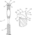
- FIG. 1 is a view in elevation of a resin bolt in accordance with a first embodiment of the invention
- FIG. 2 is a leading end portion of the resin bolt of FIG. 1 ;
- FIG. 3 is an isometric view of a penetrating end of the resin bolt of FIG. 1 ;
- FIG. 4 is a partial view in elevation of a resin bolt in accordance with a second embodiment of the invention.
- FIG. 5 is an isometric view of a penetrating end of the resin bolt of FIG. 4 ;
- FIG. 6 is a partial view in elevation of a resin bolt in accordance with a third embodiment of the invention.
- FIG. 7 is an isometric view of a penetrating end of the resin bolt of FIG. 6 ;
- FIGS. 8A, 8B and 8C are each a view in cross-section from the penetrating end of a rock bolt of FIGS. 2, 4 and 6 respectively;
- FIG. 9 is a photograph showing four columns, each row representing a single resin encased bolt, in a tube, sectioned at intervals;
- FIG. 10 is a photograph showing five rows, each row representing a single resin encased bolt, in accordance with the invention, in a tube, sectioned at intervals;
- FIG. 11 is a photograph of a series of tubes which have been sectioned to show, in each, a sectioned leading end of a resin encased rock bolt;
- FIG. 12 is a photograph of a leading end of a resin encased bolt showing the resin capsule packaging bunched towards a leading end of the bolt;
- FIG. 13 is a photograph of a resin encased resin bolt, showing a line of voids in the resin;
- FIG. 14 is a load/deflection graph representing the results of pull-out tests conducted on five samples of a resin bolt in accordance with the prior art.
- FIG. 15 is a load/deflection graph representing the results of a pull-out test conductive a five samples of a resin bolt in accordance with the invention.
- This embodiment provides a resin bolt 10 A which has an elongate solid steel shaft 12 which extends between a leading end 14 and a trailing end 16 .
- the shaft of the resin bolt 10 A in this example is of typical manufacture with a series of profiled ridges 18 formed on an outer surface of the shaft.
- the resin bolt has a pair of paddle formations, respectively designated 20 A and 20 B, which are integral to the body with the plane of each paddle offset by 90°.
- the paddles not only increase the diametric reach of the resin bolt in mixing the resin content of pre-installed resin capsules (not shown) but also increase the anchoring of the bolt within the rock hole.
- the resin bolt has an integrally formed positioning head 22 A.
- the head is peaked, extending in the elongate axis of the shaft, from a base edge or side 24 to a crown 26 which, in the examples that follow, is an apex or tip.
- the positioning head is formed with a plurality of lobes, respectively designated 28 A, 28 B, 28 C. Each of the lobes has equal lateral reach and is evenly radially spaced, this is particularly evident in FIG. 8A . Between the lobes, on a leading surface 30 , the head is indented into a plurality of concave recesses, respectively designated 32 A, 32 B and 32 C.
- Each of the lobes 28 slopes from the apex 26 to the base edge 24 .
- the slope is stepped, with a gradual sloping surface 30 A, which ends along a relief line 34 , and a steeper sloping surface 30 B, which extends between the relief line and the base edge.
- each lobe exceeds and overlaps the radial dimension of the shaft, providing a planar trailing surface 36 which extends from the base edge to the shaft 32 .
- the resin bolt 10 A is inserted into a rock hole 25 , positioning head 22 leading.
- the apex 26 of the head aids in puncturing the frangible wall of the resin capsule or capsules, which have been pre-installed into the rock hole, as the resin bolt advances.
- the lobes 28 are sized to a diameter larger than the capsule diameter to force the capsule to shred or be pushed to the very top of the hole, ahead of the leading end 14 . This prevents the gloving phenomenon from occuring.
- the concave recesses 32 provide channels for the passage of the resin contents of the ruptured capsules past the advancing positioning head, reducing resistance to the advance of the resin bolt.
- the lobes 28 also perform the function of centralizing the resin bolt, as the bolt is inserted, at least along a leading end portion 40 . This is a consequence of the lobes uniformity in both circumferential separation and lateral extent. With one or more lobes abutting the hole wall 38 at any given time, at the base edge, the bolt is keep concentric relatively to the hole.
- the resin bolt 10 A is spun, as it is inserted into the rock hole to maximise the shredding effect of the positioning head 22 A on the cartridges.
- the lobes 28 centralise the bolt in this process.
- the paddles 20 , trailing the penetrating head 22 A, can optimally mix the resin components as they travel past the penetrating head, into the annular space behind the trailing surface 36 .
- the trailing surface 36 provides a locking surface that acts against the set resin to prevent the bolt form being pulled from the hole.
- FIGS. 4 and 5 and FIGS. 6 to 7 respectively illustrate a second embodiment (resin bolt 10 B) and a third embodiment (resin bolt 10 C). Each of these embodiments differ in the number of lobes 28 on the penetrating head 22 .
- the penetrating head 22 B has four lobes, respectively designated 28 A, 28 B, 28 C and 28 D on FIG. 5 .
- the head 22 C is anvil-shaped with a pair of lobes, respectively designated 20 A and 28 B of FIG. 7 .
- the penetrating head 22 can be a discrete element which is attached to the leading end 14 of the shaft 12 . Attachment of the head can be by achieved in any suitable way.
- the head may have a threaded member on the trailing surface 36 which can engage with a threaded recess 44 in the leading end. This attachment feature is illustrated on FIG. 6 , in dotted outline.
- the head also can be fixed by welding.
- the positioning head 22 can be made of any suitable rigid material. It can be, for example, made of a rigid plastics material.
- the bolt 10 can have any suitable combination of a plurality of positioning heads ( 22 ) and paddles ( 20 ) spaced along the shaft 12 .
- a standard bolt was tested against a resin bolt in accordance with the invention.
- the standard bolt is a typical paddled bolt which has a leading end which is cropped at 45°.
- Both types of bolts were installed in steel tubes with an internal diameter of 38 mm, and encased in resin. The tubes represent a rock hole. Each sample was then sliced along its length into approximately 50 mm segments and these segments were then analysed to determine the degree of eccentricity or centralisation.
- FIG. 9 shows the 50 mm slices cut through the five test samples of these standard bolts. Eccentricity of the installed resin bolts is clearly observed. Notably, a number of the bolts were in close proximity to, or contacting, the inner wall of the steel tubes. These contact areas are designated A, B, C and D on FIG. 9 . In application underground, this eccentric positioning would offer little corrosion protection to the installed resin bolt.
- FIG. 10 shows the segments sliced from a set of five different diameter resin bolts with a tri-lobed positioning head 20 , in accordance with the first embodiment of the invention, after installation in the tubes.
- the bolt wall spin eccentrically in the tube.
- the ribs of the rotating bolt scour the resin from the inside of the tube at the point of thinnest resin annulus.
- the rotation of the bolt due to the revolution of installation machinery is indicated by a large diameter arrow and the eccentric rotation of the bolt around the tube is indicated by a small diameter arrow.
- the tri-lobed head 22 A breaks up the Mylar filling of a mastic resin capsule, the ends were cut off a number of resin bolt samples spun into steel tubes. As can be seen in FIG. 11 , the lobed head is effective at shredding the capsule as it moves through the capsule.
- FIG. 12 is an example of a resin bolt in accordance with the invention installed into a Perspex tube, encased with resin and then the tube removed.
- the Mylar packaging of the resin capsule is almost entirely located at the top of the bolt, ahead of the anchoring zone, showing that the positioning head 20 of the bolt is not only effective at shredding the packaging, it is also effective at keeping the packaging away from the anchoring zone behind the trailing surface 36 of the positioning head.
- SEPT Short Encapsulation Pull Test
- the standard bolt tested was a 20 mm deformed bar, with four anchoring paddles and a 45° cropped tip.
- the results of the SEPT are illustrated in the graph of FIG. 14 .
- the results show that two of the test samples, that is 40% tested, did not achieve a 10-ton load capacity and continued to slip through the resin at approximately 9.5 tons when tested in the 38 mm hole.
- the resin bolt of the invention was a 20 mm diameter deformed bar, with four anchoring paddles and a tri-lobe positioning formation 20 , in accordance with the first embodiment of the invention.
- the results of the SEPT on these bolts are illustrated in the graph of FIG. 15 .
- the results show that all five of the test samples achieved a 10-ton load capacity as required when tested in the 38 mm hole.
Landscapes
- Engineering & Computer Science (AREA)
- Mining & Mineral Resources (AREA)
- Structural Engineering (AREA)
- Life Sciences & Earth Sciences (AREA)
- General Life Sciences & Earth Sciences (AREA)
- Geochemistry & Mineralogy (AREA)
- Geology (AREA)
- Lining Or Joining Of Plastics Or The Like (AREA)
- Processing And Handling Of Plastics And Other Materials For Molding In General (AREA)
- Joining Of Building Structures In Genera (AREA)
- Dowels (AREA)
- Connection Of Plates (AREA)
- Insertion Pins And Rivets (AREA)
- Piles And Underground Anchors (AREA)
- Moulds For Moulding Plastics Or The Like (AREA)
- Perforating, Stamping-Out Or Severing By Means Other Than Cutting (AREA)
- Slide Fasteners, Snap Fasteners, And Hook Fasteners (AREA)
Abstract
Description
Claims (5)
Applications Claiming Priority (3)
| Application Number | Priority Date | Filing Date | Title |
|---|---|---|---|
| ZA201703891 | 2017-06-07 | ||
| ZA2017/03891 | 2017-06-07 | ||
| PCT/ZA2018/050031 WO2018227218A2 (en) | 2017-06-07 | 2018-06-07 | A resin anchored rock bolt with a piercing end |
Publications (2)
| Publication Number | Publication Date |
|---|---|
| US20200088031A1 US20200088031A1 (en) | 2020-03-19 |
| US10815780B2 true US10815780B2 (en) | 2020-10-27 |
Family
ID=62981362
Family Applications (1)
| Application Number | Title | Priority Date | Filing Date |
|---|---|---|---|
| US16/616,829 Active US10815780B2 (en) | 2017-06-07 | 2018-06-07 | Resin anchored rock bolt with a piercing end |
Country Status (13)
| Country | Link |
|---|---|
| US (1) | US10815780B2 (en) |
| EP (1) | EP3635219B1 (en) |
| AR (1) | AR112130A1 (en) |
| AU (1) | AU2018280066B2 (en) |
| CA (1) | CA3063763A1 (en) |
| CL (1) | CL2019003401A1 (en) |
| ES (1) | ES2897299T3 (en) |
| MX (1) | MX2019014079A (en) |
| PE (1) | PE20200114A1 (en) |
| PL (1) | PL3635219T3 (en) |
| PT (1) | PT3635219T (en) |
| WO (1) | WO2018227218A2 (en) |
| ZA (1) | ZA201803771B (en) |
Families Citing this family (1)
| Publication number | Priority date | Publication date | Assignee | Title |
|---|---|---|---|---|
| USD922864S1 (en) * | 2019-03-14 | 2021-06-22 | Epiroc Drilling Tools Ab | Resin anchored rock bolt |
Citations (6)
| Publication number | Priority date | Publication date | Assignee | Title |
|---|---|---|---|---|
| US3973409A (en) * | 1974-07-05 | 1976-08-10 | Kabushiki Kaisha Takechi Koumusho | Apparatus for establishing an anchor |
| US4055051A (en) | 1976-01-08 | 1977-10-25 | The United States Of America As Represented By The Secretary Of The Interior | Unitary drill bit and roof bolt |
| US4744699A (en) | 1986-05-19 | 1988-05-17 | Baker International Corporation | Single-pass roof bolt and apparatus and method for installation |
| WO1996007015A1 (en) | 1994-08-30 | 1996-03-07 | Industrial Rollformers Pty. Limited | A rock bolt and method of installing a rock bolt |
| DE102010004926A1 (en) * | 2009-05-20 | 2010-11-25 | Minova International Ltd., Chesterfield | Mountain anchor (Klebanker) with separate mixing and discharge head |
| WO2013152393A1 (en) | 2012-04-10 | 2013-10-17 | Wmc Nominees Pty Limited | Rock bolt resin mixer |
-
2018
- 2018-06-07 ZA ZA2018/03771A patent/ZA201803771B/en unknown
- 2018-06-07 PE PE2019002457A patent/PE20200114A1/en unknown
- 2018-06-07 PL PL18743667T patent/PL3635219T3/en unknown
- 2018-06-07 EP EP18743667.0A patent/EP3635219B1/en active Active
- 2018-06-07 PT PT187436670T patent/PT3635219T/en unknown
- 2018-06-07 ES ES18743667T patent/ES2897299T3/en active Active
- 2018-06-07 US US16/616,829 patent/US10815780B2/en active Active
- 2018-06-07 CA CA3063763A patent/CA3063763A1/en active Pending
- 2018-06-07 AU AU2018280066A patent/AU2018280066B2/en active Active
- 2018-06-07 WO PCT/ZA2018/050031 patent/WO2018227218A2/en not_active Ceased
- 2018-06-07 MX MX2019014079A patent/MX2019014079A/en unknown
- 2018-06-08 AR ARP180101543A patent/AR112130A1/en active IP Right Grant
-
2019
- 2019-11-22 CL CL2019003401A patent/CL2019003401A1/en unknown
Patent Citations (7)
| Publication number | Priority date | Publication date | Assignee | Title |
|---|---|---|---|---|
| US3973409A (en) * | 1974-07-05 | 1976-08-10 | Kabushiki Kaisha Takechi Koumusho | Apparatus for establishing an anchor |
| US4055051A (en) | 1976-01-08 | 1977-10-25 | The United States Of America As Represented By The Secretary Of The Interior | Unitary drill bit and roof bolt |
| US4744699A (en) | 1986-05-19 | 1988-05-17 | Baker International Corporation | Single-pass roof bolt and apparatus and method for installation |
| WO1996007015A1 (en) | 1994-08-30 | 1996-03-07 | Industrial Rollformers Pty. Limited | A rock bolt and method of installing a rock bolt |
| US6033153A (en) | 1994-08-30 | 2000-03-07 | Industrial Rollformers Pty. Limited | Rock bolt and method of installing a rock bolt |
| DE102010004926A1 (en) * | 2009-05-20 | 2010-11-25 | Minova International Ltd., Chesterfield | Mountain anchor (Klebanker) with separate mixing and discharge head |
| WO2013152393A1 (en) | 2012-04-10 | 2013-10-17 | Wmc Nominees Pty Limited | Rock bolt resin mixer |
Non-Patent Citations (1)
| Title |
|---|
| International Search Report (ISR), dated Dec. 10, 2018, from corresponding international application No. PCT/ZA2018/050031. |
Also Published As
| Publication number | Publication date |
|---|---|
| AU2018280066B2 (en) | 2024-01-11 |
| WO2018227218A2 (en) | 2018-12-13 |
| ES2897299T3 (en) | 2022-02-28 |
| AR112130A1 (en) | 2019-09-25 |
| PL3635219T3 (en) | 2022-04-19 |
| AU2018280066A1 (en) | 2019-11-28 |
| CA3063763A1 (en) | 2018-12-13 |
| CL2019003401A1 (en) | 2020-03-20 |
| EP3635219B1 (en) | 2021-08-18 |
| EP3635219A2 (en) | 2020-04-15 |
| ZA201803771B (en) | 2024-08-28 |
| US20200088031A1 (en) | 2020-03-19 |
| PE20200114A1 (en) | 2020-01-16 |
| PT3635219T (en) | 2021-11-02 |
| MX2019014079A (en) | 2020-08-06 |
| WO2018227218A3 (en) | 2019-01-17 |
Similar Documents
| Publication | Publication Date | Title |
|---|---|---|
| US9057169B1 (en) | Sacrificial tip and method of installing a friction pile | |
| US7338234B2 (en) | Rock bolt | |
| US8215875B2 (en) | Bolt anchor | |
| AU2007217128B2 (en) | Injection bolt with a fixed static mixer | |
| US10823219B2 (en) | Thread-forming screw with separate thread sprial and different part flank angles | |
| US8282318B2 (en) | Roof bolt anchor with camming element | |
| AU2011335895B2 (en) | A nut assembly | |
| US10815780B2 (en) | Resin anchored rock bolt with a piercing end | |
| CA2576116A1 (en) | Rock bolt with grout flow geometry | |
| EP3000963B1 (en) | Mine support assembly for anchoring in a bore hole in the form of an improved rock bolt | |
| US20110185649A1 (en) | Helical Anchor with Lead | |
| AU2009208398B2 (en) | Rock bolt assembly | |
| AU2019216876B2 (en) | Rock bolt | |
| US20030031525A1 (en) | Resin embedded rock bolt | |
| US20200088032A1 (en) | A resin anchored rock bolt with a locating formation at a leading end | |
| AU2004200570A1 (en) | Rock Bolt Assembly | |
| AU2014203249A1 (en) | Rock bolt | |
| AU2014203250A1 (en) | Rock bolt | |
| AU2019101267A4 (en) | Tubular Nut for a Rock Bolt | |
| AU2013204193B2 (en) | A cable bolt assembly | |
| AU2007201848B2 (en) | A nut and rock bolt assembly | |
| WO2013033760A1 (en) | A tensionable cable bolt assembly | |
| WO2005106201A1 (en) | Locking member, a nut break-out device and a nut break-out system containing same |
Legal Events
| Date | Code | Title | Description |
|---|---|---|---|
| FEPP | Fee payment procedure |
Free format text: ENTITY STATUS SET TO UNDISCOUNTED (ORIGINAL EVENT CODE: BIG.); ENTITY STATUS OF PATENT OWNER: LARGE ENTITY |
|
| STPP | Information on status: patent application and granting procedure in general |
Free format text: NON FINAL ACTION MAILED |
|
| AS | Assignment |
Owner name: EPIROC HOLDINGS SOUTH AFRICA (PTY) LTD, SOUTH AFRICA Free format text: ASSIGNMENT OF ASSIGNORS INTEREST;ASSIGNORS:CROMPTON, BRENDAN ROBERT;SHEPPARD, JAMES WILLIAM;REEL/FRAME:052834/0158 Effective date: 20200528 |
|
| STPP | Information on status: patent application and granting procedure in general |
Free format text: RESPONSE TO NON-FINAL OFFICE ACTION ENTERED AND FORWARDED TO EXAMINER |
|
| AS | Assignment |
Owner name: EPIROC DRILLING TOOLS AB, SWEDEN Free format text: ASSIGNMENT OF ASSIGNORS INTEREST;ASSIGNOR:EPIROC HOLDINGS SOUTH AFRICA (PTY) LTD;REEL/FRAME:053668/0109 Effective date: 20200902 |
|
| STPP | Information on status: patent application and granting procedure in general |
Free format text: PUBLICATIONS -- ISSUE FEE PAYMENT VERIFIED |
|
| STCF | Information on status: patent grant |
Free format text: PATENTED CASE |
|
| AS | Assignment |
Owner name: EPIROC DRILLING TOOLS AB, SWEDEN Free format text: MEMORANDUM OF CONFIRMATION OF ASSIGNMENT;ASSIGNOR:EPIROC HOLDINGS SOUTH AFRICA (PTY) LTD;REEL/FRAME:054120/0743 Effective date: 20201007 |
|
| MAFP | Maintenance fee payment |
Free format text: PAYMENT OF MAINTENANCE FEE, 4TH YEAR, LARGE ENTITY (ORIGINAL EVENT CODE: M1551); ENTITY STATUS OF PATENT OWNER: LARGE ENTITY Year of fee payment: 4 |