US10804667B2 - Device for automatically mounting a connector-housing - Google Patents
Device for automatically mounting a connector-housing Download PDFInfo
- Publication number
- US10804667B2 US10804667B2 US15/318,704 US201515318704A US10804667B2 US 10804667 B2 US10804667 B2 US 10804667B2 US 201515318704 A US201515318704 A US 201515318704A US 10804667 B2 US10804667 B2 US 10804667B2
- Authority
- US
- United States
- Prior art keywords
- gripper
- alignment
- contact part
- mounting
- contact
- Prior art date
- Legal status (The legal status is an assumption and is not a legal conclusion. Google has not performed a legal analysis and makes no representation as to the accuracy of the status listed.)
- Expired - Fee Related, expires
Links
- 238000003780 insertion Methods 0.000 claims description 15
- 230000037431 insertion Effects 0.000 claims description 15
- 230000000717 retained effect Effects 0.000 claims 4
- 238000000034 method Methods 0.000 description 38
- 230000008901 benefit Effects 0.000 description 4
- 238000002788 crimping Methods 0.000 description 3
- 210000001331 nose Anatomy 0.000 description 3
- 238000006073 displacement reaction Methods 0.000 description 2
- 230000001419 dependent effect Effects 0.000 description 1
- 238000001514 detection method Methods 0.000 description 1
- 239000012636 effector Substances 0.000 description 1
- 239000011888 foil Substances 0.000 description 1
- 238000004519 manufacturing process Methods 0.000 description 1
- 238000012067 mathematical method Methods 0.000 description 1
- 238000013178 mathematical model Methods 0.000 description 1
- 238000011144 upstream manufacturing Methods 0.000 description 1
Images


Classifications
-
- H—ELECTRICITY
- H01—ELECTRIC ELEMENTS
- H01R—ELECTRICALLY-CONDUCTIVE CONNECTIONS; STRUCTURAL ASSOCIATIONS OF A PLURALITY OF MUTUALLY-INSULATED ELECTRICAL CONNECTING ELEMENTS; COUPLING DEVICES; CURRENT COLLECTORS
- H01R43/00—Apparatus or processes specially adapted for manufacturing, assembling, maintaining, or repairing of line connectors or current collectors or for joining electric conductors
- H01R43/20—Apparatus or processes specially adapted for manufacturing, assembling, maintaining, or repairing of line connectors or current collectors or for joining electric conductors for assembling or disassembling contact members with insulating base, case or sleeve
-
- H—ELECTRICITY
- H01—ELECTRIC ELEMENTS
- H01R—ELECTRICALLY-CONDUCTIVE CONNECTIONS; STRUCTURAL ASSOCIATIONS OF A PLURALITY OF MUTUALLY-INSULATED ELECTRICAL CONNECTING ELEMENTS; COUPLING DEVICES; CURRENT COLLECTORS
- H01R43/00—Apparatus or processes specially adapted for manufacturing, assembling, maintaining, or repairing of line connectors or current collectors or for joining electric conductors
- H01R43/28—Apparatus or processes specially adapted for manufacturing, assembling, maintaining, or repairing of line connectors or current collectors or for joining electric conductors for wire processing before connecting to contact members, not provided for in groups H01R43/02 - H01R43/26
-
- H—ELECTRICITY
- H05—ELECTRIC TECHNIQUES NOT OTHERWISE PROVIDED FOR
- H05K—PRINTED CIRCUITS; CASINGS OR CONSTRUCTIONAL DETAILS OF ELECTRIC APPARATUS; MANUFACTURE OF ASSEMBLAGES OF ELECTRICAL COMPONENTS
- H05K13/00—Apparatus or processes specially adapted for manufacturing or adjusting assemblages of electric components
- H05K13/04—Mounting of components, e.g. of leadless components
- H05K13/0404—Pick-and-place heads or apparatus, e.g. with jaws
- H05K13/0408—Incorporating a pick-up tool
- H05K13/0409—Sucking devices
-
- H—ELECTRICITY
- H05—ELECTRIC TECHNIQUES NOT OTHERWISE PROVIDED FOR
- H05K—PRINTED CIRCUITS; CASINGS OR CONSTRUCTIONAL DETAILS OF ELECTRIC APPARATUS; MANUFACTURE OF ASSEMBLAGES OF ELECTRICAL COMPONENTS
- H05K13/00—Apparatus or processes specially adapted for manufacturing or adjusting assemblages of electric components
- H05K13/04—Mounting of components, e.g. of leadless components
- H05K13/0404—Pick-and-place heads or apparatus, e.g. with jaws
- H05K13/0408—Incorporating a pick-up tool
- H05K13/041—Incorporating a pick-up tool having multiple pick-up tools
-
- H—ELECTRICITY
- H05—ELECTRIC TECHNIQUES NOT OTHERWISE PROVIDED FOR
- H05K—PRINTED CIRCUITS; CASINGS OR CONSTRUCTIONAL DETAILS OF ELECTRIC APPARATUS; MANUFACTURE OF ASSEMBLAGES OF ELECTRICAL COMPONENTS
- H05K13/00—Apparatus or processes specially adapted for manufacturing or adjusting assemblages of electric components
- H05K13/08—Monitoring manufacture of assemblages
- H05K13/081—Integration of optical monitoring devices in assembly lines; Processes using optical monitoring devices specially adapted for controlling devices or machines in assembly lines
- H05K13/0812—Integration of optical monitoring devices in assembly lines; Processes using optical monitoring devices specially adapted for controlling devices or machines in assembly lines the monitoring devices being integrated in the mounting machine, e.g. for monitoring components, leads, component placement
-
- Y—GENERAL TAGGING OF NEW TECHNOLOGICAL DEVELOPMENTS; GENERAL TAGGING OF CROSS-SECTIONAL TECHNOLOGIES SPANNING OVER SEVERAL SECTIONS OF THE IPC; TECHNICAL SUBJECTS COVERED BY FORMER USPC CROSS-REFERENCE ART COLLECTIONS [XRACs] AND DIGESTS
- Y10—TECHNICAL SUBJECTS COVERED BY FORMER USPC
- Y10T—TECHNICAL SUBJECTS COVERED BY FORMER US CLASSIFICATION
- Y10T29/00—Metal working
- Y10T29/49—Method of mechanical manufacture
- Y10T29/49002—Electrical device making
- Y10T29/49117—Conductor or circuit manufacturing
- Y10T29/49124—On flat or curved insulated base, e.g., printed circuit, etc.
- Y10T29/4913—Assembling to base an electrical component, e.g., capacitor, etc.
- Y10T29/49131—Assembling to base an electrical component, e.g., capacitor, etc. by utilizing optical sighting device
-
- Y—GENERAL TAGGING OF NEW TECHNOLOGICAL DEVELOPMENTS; GENERAL TAGGING OF CROSS-SECTIONAL TECHNOLOGIES SPANNING OVER SEVERAL SECTIONS OF THE IPC; TECHNICAL SUBJECTS COVERED BY FORMER USPC CROSS-REFERENCE ART COLLECTIONS [XRACs] AND DIGESTS
- Y10—TECHNICAL SUBJECTS COVERED BY FORMER USPC
- Y10T—TECHNICAL SUBJECTS COVERED BY FORMER US CLASSIFICATION
- Y10T29/00—Metal working
- Y10T29/49—Method of mechanical manufacture
- Y10T29/49002—Electrical device making
- Y10T29/49117—Conductor or circuit manufacturing
- Y10T29/49124—On flat or curved insulated base, e.g., printed circuit, etc.
- Y10T29/4913—Assembling to base an electrical component, e.g., capacitor, etc.
- Y10T29/49133—Assembling to base an electrical component, e.g., capacitor, etc. with component orienting
-
- Y—GENERAL TAGGING OF NEW TECHNOLOGICAL DEVELOPMENTS; GENERAL TAGGING OF CROSS-SECTIONAL TECHNOLOGIES SPANNING OVER SEVERAL SECTIONS OF THE IPC; TECHNICAL SUBJECTS COVERED BY FORMER USPC CROSS-REFERENCE ART COLLECTIONS [XRACs] AND DIGESTS
- Y10—TECHNICAL SUBJECTS COVERED BY FORMER USPC
- Y10T—TECHNICAL SUBJECTS COVERED BY FORMER US CLASSIFICATION
- Y10T29/00—Metal working
- Y10T29/49—Method of mechanical manufacture
- Y10T29/49002—Electrical device making
- Y10T29/49117—Conductor or circuit manufacturing
- Y10T29/49204—Contact or terminal manufacturing
- Y10T29/49208—Contact or terminal manufacturing by assembling plural parts
-
- Y—GENERAL TAGGING OF NEW TECHNOLOGICAL DEVELOPMENTS; GENERAL TAGGING OF CROSS-SECTIONAL TECHNOLOGIES SPANNING OVER SEVERAL SECTIONS OF THE IPC; TECHNICAL SUBJECTS COVERED BY FORMER USPC CROSS-REFERENCE ART COLLECTIONS [XRACs] AND DIGESTS
- Y10—TECHNICAL SUBJECTS COVERED BY FORMER USPC
- Y10T—TECHNICAL SUBJECTS COVERED BY FORMER US CLASSIFICATION
- Y10T29/00—Metal working
- Y10T29/53—Means to assemble or disassemble
- Y10T29/5313—Means to assemble electrical device
- Y10T29/532—Conductor
- Y10T29/53209—Terminal or connector
- Y10T29/53213—Assembled to wire-type conductor
Definitions
- This disclosure generally relates to a method for automatically mounting a connector-housing having a contact-part attached to an electrical line, wherein the connector-housing is fixed to a holder and the contact-part is inserted into a cavity of the connector-housing by means of a movable-gripper.
- connection-housing is basically meant to be also a socket housing, a clamping bar or the like. To ensure a reliable and efficient mounting process, an accurate knowledge of the positions of the respective components of the system is required.
- determining the actual-rotational-position of the contact-part in step (ii) is carried out by means of a camera directed onto the held contact-part.
- the camera may be the camera with an associated image-processing-system. The use of the camera allows for a contact-free and fast detection of the rotational-position of a contact-part.
- a lens of the camera is focused on a front-end-face of the held contact-part facing away from the electrical line. This ensures optimum recognition of radial form features or markings of the contact-part in a captured image.
- the alignment process further comprises the step of: (v) performing a height-position-correction by means of the alignment-gripper holding the contact-part, if an actual height-position of the held contact-part, which indicates an axial-position in relation to the rotation-axis of a front side of the contact-part facing away from the electrical line, deviates from a predetermined reference-height-position.
- Deviations between the actual-height position and the predetermined reference-height-position may occur in particular due to tolerance-related length differences of the individually provided contact-parts.
- Such faulty positions may be prevented by an automatic height-position-correction.
- the distance between the alignment-gripper holding the contact-part and the contact-part tip is given by the protruding line length and the length of the contact-part.
- the holding of the contact-part in step (i) and the performing the rotational-position-correction in step (iv) is carried out by means of a rotatable alignment-gripper, which is separated from the mounting-gripper provided for insertion of the contact-part into the cavity, wherein the contact-part, after the rotational-position-correction in step (iv), is passed from the alignment-gripper to the mounting-gripper provided for insertion of the contact-part into the cavity while avoiding a further twist. Due to the provision of a separate alignment-gripper for the alignment process, the mounting-gripper provided for mounting is not affected by the alignment process and therefore can execute successive mounting operations without any delay. Thus, the efficiency of the entire system is not affected by the alignment process.
- the insertion of the contact-part into the cavity and the alignment process are carried out in spatially separated stations of a common mounting-device to ensure an efficient overall process.
- a previously aligned contact-part can be inserted into a cavity of a connector-housing at the mounting-station.
- the throughput of a mounting system can thereby be increased.
- Another embodiment of the invention provides that, while performing the alignment process, another subsequently to be aligned contact-part attached to an electrical line is taken from a contact-part supply by a movable supply-gripper and is placed into a supply-position.
- the overall process can be further accelerated since the supply-gripper can provide the contact-part already prepositioned for the alignment process.
- At least two contact-parts are held at the same time in step (i) by means of a multi-gripper, which in step (iv) are subjected to a common rotational-position-correction by the multi-gripper.
- a double-gripper can be provided.
- Such a double-gripper enables an especially fast mounting process, particularly in the case where an electrical line with contact-parts attached at both ends for connecting two connector-housings is to be mounted.
- a device for automatically mounting a connector-housing with a contact-part attached to an electrical line comprising a holder for fixing the connector-housing and a movable-gripper for inserting the contact-part into a cavity of the connector-housing.
- a mounting-device according to the invention comprises an alignment-station, comprising:
- At least one alignment-gripper which is configured for holding the contact-part, directly or on the electric line, and rotating the held contact-part about an rotation-axis parallel to an insertion-direction;
- the process reliability in an automatic mounting-device can be increased and the efficiency can be improved.
- the alignment-station can be procedurally arranged upstream from a mounting-station.
- the alignment-gripper is provided in addition to the mounting-gripper provided for insertion of the contact-part into the cavity.
- the mounting-gripper provided for mounting is not affected by the rotational-position-correction.
- the alignment-gripper may be configured for rotating the held contact-part by at least 90°, preferably at least 180°. This allows for a rotational-position-correction even with comparatively large misalignments or from any initial positions.
- a rotation of the gripper in such a wide rotation-angle range facilitates the positioning of individual radial form features of the contact-part, such as crimping noses, flats, grooves and the like.
- the alignment-gripper is displaceable along the rotation-axis and/or perpendicular to the rotation-axis, preferably by means of a linear-positioning-system. In this way, the correction possibilities during the alignment process can be extended.
- the benefit of a linear-positioning-system compared to a robot is that no mathematical model related nonlinearities occur.
- the alignment-gripper is configured for common holding and rotating of at least two contact-parts, in particular wherein each of the held contact-parts has its own associated camera. Multi-grippers allow for particularly fast mounting operations.
- the camera is arranged such that it is directed from a side facing away from the electrical line to the contact-part held by the alignment-gripper.
- the actual rotational-position of the contact-part is easily detectable from such a point of view.
- a mounting-camera for determining the position of the connector-housing in relation to a predetermined reference-position, wherein the movable mounting-gripper and the mounting-camera form a mounting unit configured for common movement.
- a mounting unit with its own camera can be provided, so no measuring-station including associated drives is necessary.
- the benefits of a mounting unit with its own mounting-camera are provided independently of the presence of an alignment-station, so for this aspect also independent protection is claimed.
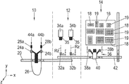
- FIG. 1 is a simplified representation of a mounting-device during provision of an electrical line including two contact-parts attached thereto in accordance with one embodiment
- FIG. 2 depicts the mounting device of FIG. 1 during the transfer of the electrical line to an alignment-station in accordance with one embodiment
- FIG. 3 depicts the mounting device of FIG. 1 during an alignment process in accordance with one embodiment
- FIG. 4 depicts the mounting device of FIG. 1 during the transfer of the electrical line to a mounting-station in accordance with one embodiment
- FIG. 5 depicts the mounting device of FIG. 1 prior to insertion of the contact-parts into respective cavities of connector-housings in accordance with one embodiment
- FIG. 6 depicts the mounting device of FIG. 1 after insertion of the contact-parts into the cavities in accordance with one embodiment
- FIG. 7 depicts the mounting device of FIG. 1 during a calibration process in accordance with one embodiment.
- the mounting device illustrated in simplified form in the FIGS. 1 to 7 includes a supply-station 10 , an alignment-station 12 and a mounting-station 14 , which are arranged spatially separated, here in direct succession.
- a stationary fixable holder 16 for a plurality of connector-housings 18 is provided in the area of the mounting-station 14 .
- the connector-housings 18 can be locked in receptacles of the panel-like holder 16 , optionally using additional holders.
- the connector-housings 18 exemplified in different configurations each comprise several cavities 19 .
- a first-positioning-system 20 here in the form of a uniaxial linear system, is associated with the supply-station 10 and is used to move two adjacent supply-grippers 24 a , 24 b which are combined into a double-gripper.
- an electrical line 26 is recognizable in the area of the supply-station 10 , which is provided at both ends with respective contact-parts 28 a , 28 b .
- Each of the contact-parts 28 a , 28 b is held at the electrical line 26 by one of the supply-grippers 24 a , 24 b .
- the supply-grippers 24 a , 24 b could also be configured for directly holding the contact-parts 28 a , 28 b.
- Two adjacent alignment-grippers 32 a , 32 b are provided in the area of the alignment-station 12 , which may also combined into a double-gripper dependent on the application.
- the alignment-grippers 32 a , 32 b may be similar in principle as the supply-grippers 24 a , 24 b .
- the alignment-grippers 32 a , 32 b are each configured to be rotatable for rotating a held contact-part 28 a , 28 b about a rotation-axis Rz, preferably by 180°.
- the alignment-grippers 32 a , 32 b are each linearly displaceable along the rotation-axis Rz, as indicated by the straight double-arrows.
- Two alignment-cameras 34 a , 34 b including respective image-processing-systems, not shown, are arranged in the area of the alignment-station 12 and are directed to a respective one of the alignment-grippers 32 a , 32 b .
- the alignment-cameras 34 a , 34 b may also be connected to a common image-processing-system.
- a mounting-unit 36 associated with the mounting-station 14 includes two mounting-grippers 38 a , 38 b and a mounting-camera 40 with associated own or higher-level image-processing-system.
- a second-positioning-system 42 which is configured as a two-axis linear system, as shown, the mounting-unit 36 can be moved in front of the individual connector-housings 18 fixed to the holder 16 .
- the first-positioning-system 20 and the second-positioning-system 42 overlap with each other in the area of the alignment-station 12 , so that a transfer of held contact-parts 28 a , 28 b between the individual grippers is possible.
- a prefabricated electrical line 26 with two contact-parts 28 a , 28 b attached to ends is taken from a component supply, not shown, and, as shown in FIG. 1 , is brought into a provisioning position by means of the supply-grippers 24 a , 24 b .
- the contact-parts 28 a , 28 b are then moved to the alignment-station 12 by means of the first-positioning-system 20 and transferred to the alignment-grippers 32 a , 32 b . This transfer is shown in FIG. 2 . After the transfer, the supply-grippers 24 a , 24 b are moved back to their original positions, and it is immediately started with the provision of another electrical line 26 .
- the alignment-grippers 32 a , 32 b perform an alignment process by initially determining an actual-rotational-position of the held contact-parts 28 a , 28 b in relation to the respective rotation-axis Rz by means of the alignment-cameras 34 a , 34 b and the associated image-processing-systems.
- the lenses 35 of the alignment-cameras 34 a , 34 b are each focused on the front-end-faces 44 a , 44 b ( FIG. 1 ) of the held contact-parts 28 a , 28 b .
- the determined actual-rotational-position is compared to a rotational-position predetermined by the characteristics and arrangement of the connector-housing 18 to be mounted.
- a rotational-position-correction is performed by appropriately rotating the alignment-grippers 32 a , 32 b .
- the two contact-parts 28 a , 28 b are displaced along the respective rotation-axis Rz by means of the alignment-grippers 32 a , 32 b , as necessary, so that the front-end-faces 44 a , 44 b of the contact-parts 28 a , 28 b are on a common reference line 46 extending perpendicular to the rotation-axes Rz ( FIG. 3 ).
- the mounting-unit 36 is subsequently or even during the alignment process moved to the alignment-station 12 .
- the two ends of the electrical line 26 with the contact-parts 28 a , 28 b are transferred from the alignment-grippers 32 a , 32 b to the mounting-grippers 38 a , 38 b , as shown in FIG. 4 .
- the transfer is carried out, while avoiding a rotation of the contact-parts 28 a , 28 b .
- potential deviations of the positions of the contact-parts 28 a , 28 b are determined in a x-y plane perpendicular to the rotational axes Rz in relation to the respective reference positions.
- the movement is respectively stopped and the mounting-gripper 38 a is moved in the insertion-direction E towards the marking-carrier 48 until the tip of the marking-device 52 a contacts therewith and thus sets a marking-point 55 .
- another row of marking-points 55 is created with altered Y position.
- the row by row setting of marking-points 55 is repeated until the entire marking-carrier 48 is covered by a grid-like array of points, as shown.
- the mounting-camera 40 of the mounting-unit 36 is successively moved to the individual marking-points 55 by the second-positioning-system 42 and the positions of the marking-points 55 on the marking-carrier 48 are determined by the displacement-position of the second-positioning-system 42 and the position of the marking-point 55 in the captured image.
- the thus determined positions of the marking-points 55 are stored together with the displacement coordinates of the second-positioning-system 42 in a storage-device.
- the calibration method is repeated with the second-mounting-gripper 38 b and its associated marking-device 52 b.
- the respective displacement coordinates of the second-positioning-system 42 can be determined from the positions of the connector-housings 18 at the holder 16 using the stored data.
- intermediate values can be determined by suitable mathematical methods, for example by an interpolation method. Any deviations from an orthogonal and linear movement of the mounting-unit 36 , which for example lead to a trapezoidal, cushion-like or barrel-like distortion of the grid-like array of points, are determined by the calibration file and can be compensated accordingly in terms of control.
- the invention enables a particularly reliable and fast mounting of connector-housings 18 with electrical lines 26 .
- a device and method for mounting a connector-housing is provided.
- the alignment process ensures that each provided contact-part is in the correct rotational-position before the insertion process.
- the reliability of the mounting process can be considerably increased by the automatic rotational-position-correction.
Landscapes
- Engineering & Computer Science (AREA)
- Manufacturing & Machinery (AREA)
- Microelectronics & Electronic Packaging (AREA)
- Operations Research (AREA)
- Manufacturing Of Electrical Connectors (AREA)
Abstract
Description
Claims (18)
Applications Claiming Priority (4)
| Application Number | Priority Date | Filing Date | Title |
|---|---|---|---|
| EP14172588.7A EP2958201A1 (en) | 2014-06-16 | 2014-06-16 | Method and device for assembling a connector housing |
| EP14172588 | 2014-06-16 | ||
| EP14172588.7 | 2014-06-16 | ||
| PCT/EP2015/063350 WO2015193248A1 (en) | 2014-06-16 | 2015-06-15 | Device and method for automatically equipping a plug housing |
Related Parent Applications (1)
| Application Number | Title | Priority Date | Filing Date |
|---|---|---|---|
| PCT/EP2015/063350 A-371-Of-International WO2015193248A1 (en) | 2014-06-16 | 2015-06-15 | Device and method for automatically equipping a plug housing |
Related Child Applications (1)
| Application Number | Title | Priority Date | Filing Date |
|---|---|---|---|
| US17/068,289 Division US11641086B2 (en) | 2014-06-16 | 2020-10-12 | Method for automatically mounting a connector-housing |
Publications (2)
| Publication Number | Publication Date |
|---|---|
| US20170133809A1 US20170133809A1 (en) | 2017-05-11 |
| US10804667B2 true US10804667B2 (en) | 2020-10-13 |
Family
ID=50976481
Family Applications (2)
| Application Number | Title | Priority Date | Filing Date |
|---|---|---|---|
| US15/318,704 Expired - Fee Related US10804667B2 (en) | 2014-06-16 | 2015-06-15 | Device for automatically mounting a connector-housing |
| US17/068,289 Active 2036-04-08 US11641086B2 (en) | 2014-06-16 | 2020-10-12 | Method for automatically mounting a connector-housing |
Family Applications After (1)
| Application Number | Title | Priority Date | Filing Date |
|---|---|---|---|
| US17/068,289 Active 2036-04-08 US11641086B2 (en) | 2014-06-16 | 2020-10-12 | Method for automatically mounting a connector-housing |
Country Status (4)
| Country | Link |
|---|---|
| US (2) | US10804667B2 (en) |
| EP (2) | EP2958201A1 (en) |
| CN (1) | CN106663909B (en) |
| WO (1) | WO2015193248A1 (en) |
Families Citing this family (5)
| Publication number | Priority date | Publication date | Assignee | Title |
|---|---|---|---|---|
| US10649442B2 (en) | 2016-04-25 | 2020-05-12 | The Boeing Company | Methods of operating an automated machine for inserting wires into grommet cavity locations of an electrical connector |
| DE102017128295A1 (en) | 2017-11-29 | 2019-05-29 | Rittal Gmbh & Co. Kg | Method for electrical wiring of electronic components in switchgear construction and a corresponding arrangement |
| FR3079079B1 (en) * | 2018-03-16 | 2020-03-27 | Cemra | INSERTION DEVICE AND METHOD INCLUDING MEANS FOR ALIGNMENT OF THE LONGITUDINAL AXIS OF THE POD |
| DE102019207253B4 (en) * | 2019-05-17 | 2021-06-10 | Leoni Bordnetz-Systeme Gmbh | Device and method for the automatic assembly of a line pair |
| JP7364635B2 (en) * | 2021-09-27 | 2023-10-18 | 矢崎総業株式会社 | Terminal insertion method and terminal insertion device |
Citations (17)
| Publication number | Priority date | Publication date | Assignee | Title |
|---|---|---|---|---|
| US5083863A (en) * | 1989-02-28 | 1992-01-28 | Societe Anonyme Dite : Aerospatiale Societe Nationale Industrielle | System for checking the connection of conductor elements in a connector, and an automatic connection installation equipped with said system |
| US5084962A (en) * | 1988-08-24 | 1992-02-04 | Tdk Corporation | Apparatus for and method of automatically mounting electronic component on printed circuit board |
| US5588206A (en) * | 1993-11-29 | 1996-12-31 | Yazaki Corporation | Method for inserting wire-equipped terminal in connector housing |
| US5727312A (en) * | 1995-11-10 | 1998-03-17 | Yazaki Corporation | Terminal inserting method |
| US6043877A (en) | 1996-11-26 | 2000-03-28 | U.S. Philips Corporation | Calibration carrier for a component placement machine having an adhesive reflective surface |
| US20020042989A1 (en) * | 2000-08-29 | 2002-04-18 | Matsushita Electric Industrial Co., Ltd. | Parts mounting method and parts mounting apparatus |
| US20020073536A1 (en) * | 1996-08-27 | 2002-06-20 | Osamu Okuda | Component mounting apparatus |
| US20030079342A1 (en) * | 2001-10-31 | 2003-05-01 | Jean Revel | Conductor wire manipulator, machine and insertion method incorporating said manipulator |
| CN1457230A (en) | 2002-05-08 | 2003-11-19 | 富士机械制造株式会社 | Method and program for acquiring printing circuit board positioning error and electronic circuit component installating system |
| JP2007059286A (en) * | 2005-08-26 | 2007-03-08 | Asahi Seiki Kk | Wire mounting device and measurement structure |
| US20080256792A1 (en) * | 2006-12-14 | 2008-10-23 | Koji Imai | Terminal Insertion Apparatus |
| US20090199396A1 (en) | 2008-02-09 | 2009-08-13 | Cirris Systems Corporation | Apparatus for electrical pin installation and retention confirmation |
| CN101847817A (en) | 2010-03-31 | 2010-09-29 | 中航光电科技股份有限公司 | Automatic electric connector assembling method and automatic electric connector assembler |
| EP2461433A1 (en) | 2010-12-01 | 2012-06-06 | Delphi Technologies, Inc. | Method and device for manufacturing a connector housing |
| CN202817460U (en) | 2012-08-22 | 2013-03-20 | 东莞市星擎电子科技有限公司 | Automatic production machine for serial port socket |
| CN103454456A (en) | 2012-05-30 | 2013-12-18 | 三星电机株式会社 | Printed circuit board inspection apparatus and position correcting method thereof |
| US20140081464A1 (en) * | 2012-09-20 | 2014-03-20 | Tyco Electronics Corporation | Wire sorting machine and method of sorting wires |
Family Cites Families (13)
| Publication number | Priority date | Publication date | Assignee | Title |
|---|---|---|---|---|
| US3867760A (en) * | 1971-05-10 | 1975-02-25 | Molex Products Co | Printed circuit board lead wire receptacle |
| EP0348615B1 (en) | 1988-07-01 | 1994-06-15 | Komax Ag | Process for automatically mounting electrical conductors with contact elements in connector shells |
| CH689288A5 (en) | 1994-10-21 | 1999-01-29 | Komax Holding Ag | Method and apparatus for loading Steckergehaeusen. |
| BE1009814A5 (en) * | 1995-11-06 | 1997-08-05 | Framatome Connectors Belgium | Method and device for the installation of electronic components in a plate with printed circuits. |
| DE60002927T2 (en) | 1999-02-25 | 2004-05-19 | Sumitomo Wiring Systems, Ltd., Yokkaichi | Improvements in the assembly of connections with electrical conductors in plug housings |
| EP1073163B1 (en) | 1999-07-26 | 2003-05-14 | komax Holding AG | Device for feeding cable ends to a cable harness assembly apparatus |
| EP1251605B1 (en) | 2001-04-10 | 2004-07-21 | Komax Holding Ag | Apparatus and method for the insertion of cable ends into connector housings |
| EP1429430B1 (en) | 2001-10-05 | 2008-03-19 | Komax Holding Ag | Process and device for fitting connector housings with preparated cable ends of a cable |
| EP1317031B1 (en) | 2001-10-31 | 2011-01-05 | Komax Holding AG | Manipulator for wire conductors, apparatus and inserting method comprising such a manipulator |
| EP1461179B1 (en) | 2001-11-24 | 2016-01-20 | Delphi Technologies, Inc. | Improvements in wire harnesses |
| JP4079949B2 (en) * | 2005-01-20 | 2008-04-23 | 第一精工株式会社 | Connector manufacturing apparatus and connector manufacturing method |
| EP1786072B1 (en) | 2005-11-10 | 2008-07-16 | komax Holding AG | Cable processing apparatus and method to use such an apparatus |
| DE102014005242B3 (en) | 2014-04-08 | 2015-07-09 | SLE quality engineering GmbH & Co. KG | Method and device for determining an angular position of individual lines at a predetermined cross-sectional location in a multi-core sheathed cable |
-
2014
- 2014-06-16 EP EP14172588.7A patent/EP2958201A1/en not_active Withdrawn
-
2015
- 2015-06-15 CN CN201580032079.9A patent/CN106663909B/en not_active Expired - Fee Related
- 2015-06-15 US US15/318,704 patent/US10804667B2/en not_active Expired - Fee Related
- 2015-06-15 WO PCT/EP2015/063350 patent/WO2015193248A1/en not_active Ceased
- 2015-06-15 EP EP15730739.8A patent/EP3155700B1/en not_active Revoked
-
2020
- 2020-10-12 US US17/068,289 patent/US11641086B2/en active Active
Patent Citations (19)
| Publication number | Priority date | Publication date | Assignee | Title |
|---|---|---|---|---|
| US5084962A (en) * | 1988-08-24 | 1992-02-04 | Tdk Corporation | Apparatus for and method of automatically mounting electronic component on printed circuit board |
| US5083863A (en) * | 1989-02-28 | 1992-01-28 | Societe Anonyme Dite : Aerospatiale Societe Nationale Industrielle | System for checking the connection of conductor elements in a connector, and an automatic connection installation equipped with said system |
| US5588206A (en) * | 1993-11-29 | 1996-12-31 | Yazaki Corporation | Method for inserting wire-equipped terminal in connector housing |
| US5727312A (en) * | 1995-11-10 | 1998-03-17 | Yazaki Corporation | Terminal inserting method |
| US20020073536A1 (en) * | 1996-08-27 | 2002-06-20 | Osamu Okuda | Component mounting apparatus |
| US6043877A (en) | 1996-11-26 | 2000-03-28 | U.S. Philips Corporation | Calibration carrier for a component placement machine having an adhesive reflective surface |
| US20020042989A1 (en) * | 2000-08-29 | 2002-04-18 | Matsushita Electric Industrial Co., Ltd. | Parts mounting method and parts mounting apparatus |
| US20030079342A1 (en) * | 2001-10-31 | 2003-05-01 | Jean Revel | Conductor wire manipulator, machine and insertion method incorporating said manipulator |
| CN1457230A (en) | 2002-05-08 | 2003-11-19 | 富士机械制造株式会社 | Method and program for acquiring printing circuit board positioning error and electronic circuit component installating system |
| US7036215B2 (en) | 2002-05-08 | 2006-05-02 | Fuji Machine Mfg. Co., Ltd. | Method and program for obtaining positioning errors of printed-wiring board, and electronic-circuit-component mounting system |
| JP2007059286A (en) * | 2005-08-26 | 2007-03-08 | Asahi Seiki Kk | Wire mounting device and measurement structure |
| US20080256792A1 (en) * | 2006-12-14 | 2008-10-23 | Koji Imai | Terminal Insertion Apparatus |
| US20090199396A1 (en) | 2008-02-09 | 2009-08-13 | Cirris Systems Corporation | Apparatus for electrical pin installation and retention confirmation |
| CN101847817A (en) | 2010-03-31 | 2010-09-29 | 中航光电科技股份有限公司 | Automatic electric connector assembling method and automatic electric connector assembler |
| EP2461433A1 (en) | 2010-12-01 | 2012-06-06 | Delphi Technologies, Inc. | Method and device for manufacturing a connector housing |
| US20120304439A1 (en) | 2010-12-01 | 2012-12-06 | Delphi Technologies, Inc. | Method and apparatus for fitting of a plug housing |
| CN103454456A (en) | 2012-05-30 | 2013-12-18 | 三星电机株式会社 | Printed circuit board inspection apparatus and position correcting method thereof |
| CN202817460U (en) | 2012-08-22 | 2013-03-20 | 东莞市星擎电子科技有限公司 | Automatic production machine for serial port socket |
| US20140081464A1 (en) * | 2012-09-20 | 2014-03-20 | Tyco Electronics Corporation | Wire sorting machine and method of sorting wires |
Non-Patent Citations (1)
| Title |
|---|
| Machine Translation of European Patent Publication, EP 2 461 433, Apr. 2020. (Year: 2012). * |
Also Published As
| Publication number | Publication date |
|---|---|
| EP3155700A1 (en) | 2017-04-19 |
| EP2958201A1 (en) | 2015-12-23 |
| CN106663909A (en) | 2017-05-10 |
| US20170133809A1 (en) | 2017-05-11 |
| EP3155700B1 (en) | 2018-07-11 |
| CN106663909B (en) | 2019-02-15 |
| US11641086B2 (en) | 2023-05-02 |
| WO2015193248A1 (en) | 2015-12-23 |
| US20210028589A1 (en) | 2021-01-28 |
Similar Documents
| Publication | Publication Date | Title |
|---|---|---|
| US11641086B2 (en) | Method for automatically mounting a connector-housing | |
| US11276992B2 (en) | Method for electrical cabling with a cable sequence of electronic components in switchgear construction and a corresponding robot arrangement | |
| US11171431B2 (en) | Component insertion device with dummy component, and component insertion method and computer readable recording medium of using the same | |
| US12030193B2 (en) | Method for robot-assisted wiring of electrical components of an electrical switchgear arranged on a mounting plate | |
| KR101753018B1 (en) | Production device for wire harness and production method therefor | |
| WO2019026370A1 (en) | Coil segment forming device, coil segment forming method, and rotating electric machine manufacturing device | |
| US20150108202A1 (en) | Automatic Soldering System | |
| WO2015029710A1 (en) | Production device for wire harness and production method therefor | |
| US11589489B2 (en) | Lead wire straightening device | |
| US20220013996A1 (en) | Method for wiring electrical components of an electrical switchgear arranged on a mounting plate | |
| EP3439449B1 (en) | Operation checking device of electronic component mounting machine | |
| EP3477798B1 (en) | Assembly system | |
| US20180236658A1 (en) | Assembly System and Method For Inserting a Terminal Into a Housing | |
| TW201539904A (en) | Terminal insertion device and wiring module production method | |
| JPH07235360A (en) | Connector housing supplying device | |
| CN119253385A (en) | Terminal line double-end correction device and correction method | |
| US20170117678A1 (en) | Method for calibrating a mounting device | |
| JP2019140384A (en) | Component mounter with push function | |
| JP7691285B2 (en) | Automatic Soldering System | |
| JP7331584B2 (en) | LINEAR MEMBER ARRANGEMENT DEVICE AND LINEAR MEMBER ARRANGEMENT METHOD | |
| CN116507447A (en) | Cable Processing Center | |
| CN117154495A (en) | An automatic insertion system, method and control terminal for electrical connector contacts | |
| JP2008004619A (en) | Positioning method and positioning device | |
| EP3713385B1 (en) | Work machine and mounting method | |
| WO2017204296A1 (en) | Gas sensor assembling device and assembling method |
Legal Events
| Date | Code | Title | Description |
|---|---|---|---|
| AS | Assignment |
Owner name: DELPHI TECHNOLOGIES, INC., MICHIGAN Free format text: ASSIGNMENT OF ASSIGNORS INTEREST;ASSIGNOR:LARISCH, MARKUS;REEL/FRAME:041129/0578 Effective date: 20170117 |
|
| AS | Assignment |
Owner name: APTIV TECHNOLOGIES LIMITED, BARBADOS Free format text: ASSIGNMENT OF ASSIGNORS INTEREST;ASSIGNOR:DELPHI TECHNOLOGIES INC.;REEL/FRAME:047153/0902 Effective date: 20180101 |
|
| STPP | Information on status: patent application and granting procedure in general |
Free format text: NON FINAL ACTION MAILED |
|
| STPP | Information on status: patent application and granting procedure in general |
Free format text: RESPONSE TO NON-FINAL OFFICE ACTION ENTERED AND FORWARDED TO EXAMINER |
|
| STPP | Information on status: patent application and granting procedure in general |
Free format text: FINAL REJECTION MAILED |
|
| STPP | Information on status: patent application and granting procedure in general |
Free format text: ADVISORY ACTION MAILED |
|
| STPP | Information on status: patent application and granting procedure in general |
Free format text: DOCKETED NEW CASE - READY FOR EXAMINATION |
|
| STPP | Information on status: patent application and granting procedure in general |
Free format text: NON FINAL ACTION MAILED |
|
| STPP | Information on status: patent application and granting procedure in general |
Free format text: NOTICE OF ALLOWANCE MAILED -- APPLICATION RECEIVED IN OFFICE OF PUBLICATIONS |
|
| STPP | Information on status: patent application and granting procedure in general |
Free format text: PUBLICATIONS -- ISSUE FEE PAYMENT RECEIVED |
|
| STCF | Information on status: patent grant |
Free format text: PATENTED CASE |
|
| FEPP | Fee payment procedure |
Free format text: MAINTENANCE FEE REMINDER MAILED (ORIGINAL EVENT CODE: REM.); ENTITY STATUS OF PATENT OWNER: LARGE ENTITY |
|
| LAPS | Lapse for failure to pay maintenance fees |
Free format text: PATENT EXPIRED FOR FAILURE TO PAY MAINTENANCE FEES (ORIGINAL EVENT CODE: EXP.); ENTITY STATUS OF PATENT OWNER: LARGE ENTITY |
|
| STCH | Information on status: patent discontinuation |
Free format text: PATENT EXPIRED DUE TO NONPAYMENT OF MAINTENANCE FEES UNDER 37 CFR 1.362 |
|
| FP | Lapsed due to failure to pay maintenance fee |
Effective date: 20241013 |