US10802285B2 - Remote optical engine for virtual reality or augmented reality headsets - Google Patents
Remote optical engine for virtual reality or augmented reality headsets Download PDFInfo
- Publication number
- US10802285B2 US10802285B2 US16/292,705 US201916292705A US10802285B2 US 10802285 B2 US10802285 B2 US 10802285B2 US 201916292705 A US201916292705 A US 201916292705A US 10802285 B2 US10802285 B2 US 10802285B2
- Authority
- US
- United States
- Prior art keywords
- optical
- frame
- optical waveguide
- image
- waveguide
- Prior art date
- Legal status (The legal status is an assumption and is not a legal conclusion. Google has not performed a legal analysis and makes no representation as to the accuracy of the status listed.)
- Active
Links
- 230000003287 optical effect Effects 0.000 title claims abstract description 237
- 230000003190 augmentative effect Effects 0.000 title abstract description 10
- 238000000034 method Methods 0.000 claims description 38
- 239000013307 optical fiber Substances 0.000 claims description 8
- 239000000463 material Substances 0.000 claims description 5
- 238000005452 bending Methods 0.000 claims 1
- 239000011521 glass Substances 0.000 description 5
- 230000005540 biological transmission Effects 0.000 description 4
- 210000003128 head Anatomy 0.000 description 4
- 239000000835 fiber Substances 0.000 description 3
- 239000004973 liquid crystal related substance Substances 0.000 description 3
- XUIMIQQOPSSXEZ-UHFFFAOYSA-N Silicon Chemical compound [Si] XUIMIQQOPSSXEZ-UHFFFAOYSA-N 0.000 description 2
- 239000011248 coating agent Substances 0.000 description 2
- 238000000576 coating method Methods 0.000 description 2
- 238000010276 construction Methods 0.000 description 2
- 229910052710 silicon Inorganic materials 0.000 description 2
- 239000010703 silicon Substances 0.000 description 2
- 238000003462 Bender reaction Methods 0.000 description 1
- 230000006978 adaptation Effects 0.000 description 1
- 239000004020 conductor Substances 0.000 description 1
- 238000010586 diagram Methods 0.000 description 1
- 230000006870 function Effects 0.000 description 1
- 230000003116 impacting effect Effects 0.000 description 1
- 238000002347 injection Methods 0.000 description 1
- 239000007924 injection Substances 0.000 description 1
- 239000012092 media component Substances 0.000 description 1
- 239000002991 molded plastic Substances 0.000 description 1
- 239000004033 plastic Substances 0.000 description 1
- 229920000642 polymer Polymers 0.000 description 1
- 229920001296 polysiloxane Polymers 0.000 description 1
- 238000002310 reflectometry Methods 0.000 description 1
- 238000009877 rendering Methods 0.000 description 1
- 238000000926 separation method Methods 0.000 description 1
- 230000007704 transition Effects 0.000 description 1
Images


Classifications
-
- G—PHYSICS
- G02—OPTICS
- G02B—OPTICAL ELEMENTS, SYSTEMS OR APPARATUS
- G02B27/00—Optical systems or apparatus not provided for by any of the groups G02B1/00 - G02B26/00, G02B30/00
- G02B27/01—Head-up displays
- G02B27/017—Head mounted
- G02B27/0172—Head mounted characterised by optical features
-
- G—PHYSICS
- G06—COMPUTING; CALCULATING OR COUNTING
- G06F—ELECTRIC DIGITAL DATA PROCESSING
- G06F3/00—Input arrangements for transferring data to be processed into a form capable of being handled by the computer; Output arrangements for transferring data from processing unit to output unit, e.g. interface arrangements
- G06F3/14—Digital output to display device ; Cooperation and interconnection of the display device with other functional units
- G06F3/147—Digital output to display device ; Cooperation and interconnection of the display device with other functional units using display panels
-
- G—PHYSICS
- G09—EDUCATION; CRYPTOGRAPHY; DISPLAY; ADVERTISING; SEALS
- G09G—ARRANGEMENTS OR CIRCUITS FOR CONTROL OF INDICATING DEVICES USING STATIC MEANS TO PRESENT VARIABLE INFORMATION
- G09G5/00—Control arrangements or circuits for visual indicators common to cathode-ray tube indicators and other visual indicators
- G09G5/003—Details of a display terminal, the details relating to the control arrangement of the display terminal and to the interfaces thereto
- G09G5/006—Details of the interface to the display terminal
-
- G—PHYSICS
- G02—OPTICS
- G02B—OPTICAL ELEMENTS, SYSTEMS OR APPARATUS
- G02B27/00—Optical systems or apparatus not provided for by any of the groups G02B1/00 - G02B26/00, G02B30/00
- G02B27/01—Head-up displays
- G02B27/0101—Head-up displays characterised by optical features
- G02B2027/0132—Head-up displays characterised by optical features comprising binocular systems
- G02B2027/0134—Head-up displays characterised by optical features comprising binocular systems of stereoscopic type
-
- G—PHYSICS
- G02—OPTICS
- G02B—OPTICAL ELEMENTS, SYSTEMS OR APPARATUS
- G02B27/00—Optical systems or apparatus not provided for by any of the groups G02B1/00 - G02B26/00, G02B30/00
- G02B27/01—Head-up displays
- G02B27/0149—Head-up displays characterised by mechanical features
- G02B2027/015—Head-up displays characterised by mechanical features involving arrangement aiming to get less bulky devices
-
- G—PHYSICS
- G02—OPTICS
- G02B—OPTICAL ELEMENTS, SYSTEMS OR APPARATUS
- G02B27/00—Optical systems or apparatus not provided for by any of the groups G02B1/00 - G02B26/00, G02B30/00
- G02B27/01—Head-up displays
- G02B27/017—Head mounted
- G02B2027/0178—Eyeglass type
-
- G—PHYSICS
- G02—OPTICS
- G02B—OPTICAL ELEMENTS, SYSTEMS OR APPARATUS
- G02B27/00—Optical systems or apparatus not provided for by any of the groups G02B1/00 - G02B26/00, G02B30/00
- G02B27/42—Diffraction optics, i.e. systems including a diffractive element being designed for providing a diffractive effect
- G02B27/4205—Diffraction optics, i.e. systems including a diffractive element being designed for providing a diffractive effect having a diffractive optical element [DOE] contributing to image formation, e.g. whereby modulation transfer function MTF or optical aberrations are relevant
-
- G—PHYSICS
- G09—EDUCATION; CRYPTOGRAPHY; DISPLAY; ADVERTISING; SEALS
- G09G—ARRANGEMENTS OR CIRCUITS FOR CONTROL OF INDICATING DEVICES USING STATIC MEANS TO PRESENT VARIABLE INFORMATION
- G09G2370/00—Aspects of data communication
- G09G2370/02—Networking aspects
- G09G2370/022—Centralised management of display operation, e.g. in a server instead of locally
-
- G—PHYSICS
- G09—EDUCATION; CRYPTOGRAPHY; DISPLAY; ADVERTISING; SEALS
- G09G—ARRANGEMENTS OR CIRCUITS FOR CONTROL OF INDICATING DEVICES USING STATIC MEANS TO PRESENT VARIABLE INFORMATION
- G09G2370/00—Aspects of data communication
- G09G2370/18—Use of optical transmission of display information
Definitions
- the following description relates to optics transmission over a distance. More particularly, the following description relates to augmented reality (AR) and virtual reality (VR) headsets.
- AR augmented reality
- VR virtual reality
- Augmented reality (AR) and virtual reality (VR) headsets allow an electronically generated image to be formed on a display of the headset and viewed by a user while the user wears the headset.
- the electronic image can appear to be some distance in front of the user, beyond the headset, and can also appear to be three-dimensional.
- VR headsets show the generated image to the user, often closing off the user's vision of the outside world.
- AR headsets are mostly transparent and show the electronically generated image while allowing the user to view the outside real world through the headset.
- the generated image may be superimposed on features of the real world within the user's field of vision, for instance.
- AR and VR headsets can often be thick and bulky due to the display, optical engines, other optical elements and associated electronics attached to the headset, often at the front and sides of the headset. They can also be heavy, may need a lot of processing power to generate a bright image on the headset, and can be a source of undesirable heat, for the same reasons.
- devices and systems illustrated in the figures are shown as having a multiplicity of components.
- Various implementations of devices and/or systems, as described herein, may include fewer components and remain within the scope of the disclosure.
- other implementations of devices and/or systems may include additional components, or various combinations of the described components, and remain within the scope of the disclosure.
- FIG. 1 shows an example VR/AR headset system with remote optical engine, according to an embodiment.
- FIG. 2 shows an example VR/AR headset system with remote optical engine, according to another embodiment.
- FIG. 3 shows an example flexible waveguide, according to an embodiment.
- FIG. 4 shows a comparison of display orientations, according to an embodiment.
- FIG. 5 shows an example VR/AR headset, according to an embodiment.
- FIG. 6 shows an example of optical image transmission on a VR/AR headset, according to an embodiment.
- FIGS. 7 and 8 show an example of virtual image generation on a VR/AR headset, according to an embodiment.
- FIGS. 9 and 10 show a lens arrangement for virtual image generation on a VR/AR headset, according to an embodiment.
- FIG. 11 shows an example of virtual image generation using partially reflective mirrors.
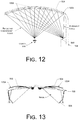
- FIGS. 12 and 13 show a lens arrangement for virtual image generation on a VR/AR headset, according to another embodiment.
- FIG. 14 is a flow diagram illustrating an example process for forming virtual images using a VR/AR headset system with remote optical engine, according to an implementation.
- a virtual reality/augmented reality (VR/AR) headset system (including the capability for one or both of virtual reality and augmented reality) is arranged to include a remote optical engine.
- the remote disposition of the optical engine removes many or all of the components of the VR/AR headset system that add weight, heat, and other characteristics that can add to user discomfort in using the system from the headset. This allows the headset to be lighter and more comfortable for the user to wear, particularly over an extended length of time.
- an electronic image is received and/or generated remotely at an optical engine, and is transmitted optically from the remote location to the headset to be viewed by the user.
- One or more optical waveguides may be used to transmit the image from the optical engine and display placed remotely and projected directly into the waveguide within the headset.
- one or more optical waveguides may be used to transmit the electronic image to one or more passive displays of the headset, from the remote optical engine.
- an electronic image is generated remotely at an optical engine and is transmitted wirelessly (e.g.
- Wi-Fi Wi-Fi, Bluetooth, ZigBee, Zwave, 3G, 4G, 5G, etc.
- a light source e.g., LEDs
- passive displays within the headset.
- the system may include a head-mountable frame (such as a glasses frame, headset frame, or the like) configured to be worn by a user to view an electronically generated image.
- a head-mountable frame such as a glasses frame, headset frame, or the like
- the frame has a minimal weight, and may have a minimal frame construction, due to the remote location of the optical engine and processing system.
- the frame includes a viewing area configured for viewing the electronically generated image.
- the system may also include a processing unit disposed remote from the frame, arranged to receive and/or to process an electrical image signal and to generate a processed electrical image signal. Also included is an optical engine disposed remote from the frame and electrically coupled to the processing unit. In the implementations, the optical engine is arranged to receive the processed electrical image signal from the processing unit and to generate an optical image.
- an optical waveguide is coupled at a first end to the frame and coupled at a second end to the optical engine.
- the optical waveguide can be arranged to deliver the entire optical image from the optical engine to the viewing area of the frame for viewing by the user.
- the optical waveguide is flexible (e.g., flexible optical cable, etc.) or partly flexible (e.g., rigid sections coupled by flexible optical couplers).
- a second optical waveguide is coupled at a first end to the frame and coupled at a second end to the optical engine.
- the first optical waveguide is arranged to deliver a first part of a stereoscopic optical image to a first part of the viewing area of the frame and the second optical waveguide is arranged to deliver a second part of the stereoscopic optical image to a second part of the viewing area of the frame.
- the first optical waveguide may deliver a “left-eye” image to a left-portion (e.g., a left-side lens) of the frame and the second optical waveguide may deliver a “right-eye” image to a right-portion (e.g., a right-side lens) of the frame for forming a stereoscopic image to the user.
- the second optical waveguide is also flexible or partly flexible.
- the one or more flexible optical cables are arranged to simultaneously deliver multiple different optical images superimposed in a field of view of the user. One or more of the multiple different optical images can have different focal distances from a point of view of the user, to form the stereoscopic image.
- the frame may include one or more rigid optical waveguides integral to or coupled to the frame.
- a rigid optical waveguide is coupled to the viewing area at a first end and coupled to the (e.g., flexible or partly flexible) optical waveguide at a second end.
- the rigid optical waveguide can be arranged to deliver the entire optical image to the viewing area of the frame from the flexible or partly flexible optical wave guide.
- each portion (e.g., left and right portions) of the viewing area includes a rigid optical waveguide configured to deliver an optical image to the respective viewing area portions.
- components of a virtual reality (VR) or augmented reality (AR) system can include: the frame or headset, which is desirable to keep as small and light as possible; optics of the headset, including glass or plastic lenses, mirrors, waveguides, and the like for directing, focusing, and displaying the image; an optical engine, including a liquid crystal display (LCD), liquid crystal on silicon (LCOS) display, digital light processing (DLP) display, microLED display, or the like, for converting an electrical signal to an optical signal and delivering the image to the optics; a processing unit (CPU and/or GPU) including electronics for receiving and processing an electrical image signal (the processing electronics portion usually includes one or more signal inputs), and delivering the electrical signal to the optical engine; a power source such as a battery; and one or more sensors, which can include a camera, accelerometer, gyroscope, GPS, compass, eye tracking sensors, and so forth, which may interface with the processing unit. Additionally, AR and VR headsets may also include audio processing electronics, audio
- Including many or all of the above components in the AR and VR headset can cause the headset to be thick, bulky, heavy, and hot.
- the headset can cause the headset to be thick, bulky, heavy, and hot.
- including the optical engine in the headset results in a larger headset or forces the display (LCOS, for example) to be smaller and have a lower resolution.
- the VR/AR system 100 is configured to include an optical engine 102 and/or a processing unit 104 remote from the viewing area 106 of the headset 108 , or remote from the headset 108 .
- the remote disposition of the optical engine 102 and/or the processing unit 104 removes many or all of the components of the VR/AR system 100 that add weight, heat, and other characteristics that can add to user discomfort in using the system from the viewing area 106 or from the headset 108 .
- the VR/AR system 100 includes a thin and light headset 108 (or head-mountable frame) to support the viewing area 106 .
- the user can wear the headset 108 on the user's head, with the viewing area 106 positioned in front of the user's eyes.
- the viewing area 106 may comprise two individual portions or components (such as right and left portions) separate from each other, with each portion positioned over an eye of the user.
- the viewing area 106 may be a single area or component that is divided virtually into at least two portions (such as right and left portions).
- the viewing area 106 provides a space to view an electronically generated image at the viewing area 106 of the frame 108 .
- the VR/AR system 100 includes an optical engine 102 and the processing unit 104 .
- the optical engine 102 and the processing unit 104 are integrated into a shared component or system.
- the optical engine 102 and the processing unit 104 are discrete components or systems, or are packaged separately. In either case, the optical engine 102 (including the display) and/or the processing unit 104 (including CPU and GPU) are decoupled from the frame 108 and/or the viewing area 106 .
- the optical engine 102 and the processing unit 104 are not mounted to the body of the headset 108 .
- the optical engine 102 and the processing unit 104 may be worn on another part of the user, remote from the user's head, such as on a belt at the user's waist, or the like, while the headset 108 is worn on the user's head.
- the processing unit 104 (and its power supply) may be worn on the user at a location remote from the frame 108 (such as on a belt) and the optical engine 102 may be located closer to the frame 108 to minimize the length of the flexible waveguide cable and/or rigid waveguide 110 .
- the processing unit 104 may be electrically coupled to the optical engine 102 (via electrical cable 202 , e.g., HDMI, DVI, etc. or wireless connectivity).
- the optical engine 102 may be mounted to a hat or other headgear, on a neck strap, or the like, toward the back of the user's head or neck, or generally nearby the frame 108 . If the optical engine 102 is near enough, it may be coupled to the frame 108 via a rigid waveguide 204 . Otherwise, the optical engine 102 may be coupled to the frame 108 with a short flexible optical cable 110 , which may be coupled to a rigid waveguide 204 as described below.
- the processing unit 104 includes electronics for receiving and processing an electrical image signal, and for delivering the processed electrical signal to the optical engine.
- the processing unit 104 includes one or more wired and/or wireless signal inputs, to receive the image signal from the image source (which may be local or remote to the VR/AR system 100 ).
- the image signal (such as a video stream, a computer display output, etc.) may be received at the processing unit 104 (via a receiver and input/output controller, for example) from a mobile computing device, or the like.
- a central processing unit (CPU) and/or a graphics processing unit (GPU) at the processing unit 104 may process the image signal for use with the VR/AR system 100 . This may include rendering processing, resolution adaptation, stereoscopic processing, or other image processing as desired.
- the processing unit 104 is electrically coupled to the optical engine 102 . Accordingly, the processed image signal is received at the optical engine 102 from the processing unit 104 .
- the optical engine 102 is optically coupled to the frame 108 and associated optics via an optical waveguide 110 or light pipe. In the embodiments, neither the optical engine 102 nor the processing unit 104 are electrically or physically coupled to the frame 108 . In an alternate embodiment (as shown in FIG. 2 ), at least a portion of the optical engine 102 may be physically coupled to a portion of the frame 108 , yet remain remote (at least 10 cm) from the viewing area 106 . In any case, the optical engine 102 forms an optical image signal and transmits the optical image signal to the viewing area 106 by optical components (e.g., optical waveguide 110 , or other optical conductor).
- optical components e.g., optical waveguide 110 , or other optical conductor
- the waveguide 110 is made from an optically transparent (or semi-transparent) material, e.g. glass, polymer, etc., or a combination of one or more such materials.
- the cross section of the waveguide 110 may have any shape; e.g., circular, rectangular, square, hexagonal, or any other shape.
- the waveguide 110 may transfer light (or an image) using total internal reflection (TIR).
- TIR total internal reflection
- the image is reflected off the interior surfaces of the waveguide 110 as the image travels from one end of the waveguide 110 to the other (e.g., from the optical engine 102 to the viewing area 106 ).
- the waveguide 110 may have a separate reflective coating on the outside surface. The reflective coating is operative to enhance the reflectivity of the inside surface of the waveguide 110 , improving the transmission of the image through the waveguide 110 .
- the waveguide 110 may consist of a graded refractive index material, in which a refractive index of the waveguide 110 progressively reduces from the inner core to the outer surface of the waveguide 110 .
- the waveguide 110 comprises a planar waveguide arranged to transfer the optical image from the second end (i.e., the optical engine 102 end of the waveguide 110 ) of the optical waveguide 110 to the first end of the optical waveguide 110 (i.e., the viewing area 106 end of the waveguide 110 ).
- the waveguide 110 comprises a flexible waveguide 110 .
- the waveguide 110 flexes or bends, with a minimum bend radius of >2.5 times the thickness of the waveguide 110 or the light pipe.
- the flexible waveguide 110 may consist of two or more rigid waveguides 302 (e.g., injection molded plastic, glass, etc.) connected together by one or more joining pieces 304 of compliant (flexible) index matching material (e.g. Silicone, or the like).
- the quantity of flexible pieces 304 will allow for the desired bend in the waveguide 110 .
- the length of the rigid waveguides 302 are much longer compared to the length of the flexible pieces 304 in order to maintain a desired integrity of the image being transferred.
- the ratio of the length of the rigid waveguide 302 to the length of the joining pieces 304 is approximately 10:1. In other embodiments, the ratio may be greater or lesser.
- the pieces 304 joining the rigid waveguides 302 may include one or more optical elements (not shown), e.g., one or more lenses (telescopic lenses, relay lenses, etc.), mirrors, polarizers, beam benders, or the like.
- the joining pieces 304 may be flexible, or the joining pieces may be inflexible, but include a joint capable of adjusting the angle between the rigid waveguides 302 as desired.
- all signal processing and some or all image processing is done off of the frame 108 at remote components (e.g., a remote optical engine 102 and a remote processing unit 104 ).
- an optical signal is sent to the frame 108 , making the frame 108 purely passive.
- the image is formed remotely and delivered to the frame 108 optically.
- “remote” can be defined as approximately 10 cm or greater distance.
- an image may be formed at a display device 402 (liquid crystal on silicon (LCOS) device, for example) at the optical engine 102 , where an electrical signal (based on input received at the processing unit 104 , processed, and delivered to the optical engine 102 ) is converted to the image.
- LCOS liquid crystal on silicon
- the display device 402 may have a larger size to accommodate a greater resolution, for example, without impacting the size of the frame 108 .
- the image formed at the display device 402 is a light signal, and may be transferred (using an optional light source and various lenses, mirrors, and the like) to one or more optical cables, including the waveguide 110 .
- the image travels to the headset 108 and/or the viewing area 106 over the waveguide 110 .
- the image may be reduced in one or more dimensions for travel to the headset 108 and/or viewing area 106 , while preserving an image front of the optical image displayed at the viewing area 106 .
- the headset frame 108 includes a viewing area 106 , which may be physically or virtually separated into a first portion 502 and a second portion 504 . Each of the portions 502 and 504 may be fed a separate image signal (light), for stereoscopic viewing.
- the flexible or partly flexible waveguide 110 is not shown for clarity, but is intended to be coupled to the frame 108 .
- the image is formed remotely on a display 402 and transported via a light source through a flexible or partly flexible waveguide 110 , which extends from the remote optical engine 102 to the frame of the 108 .
- the waveguide 110 or optical cable may comprise an optically transparent cable (such as a fiber optic or glass cable, for instance) with a reflecting surface surrounding the cable, as discussed above.
- the image is reflected within the waveguide 110 or optical cable over a distance to the frame 108 .
- a portion of the frame 108 comprises a rigid waveguide 204 .
- the rigid waveguide 204 may be coupled to the frame 108 .
- An optical connector 506 may be used to couple the flexible waveguide 110 to the rigid waveguide 204 of the frame 108 .
- the frame 108 may include two rigid waveguides 204 (one for each portion 502 , 504 of the viewing area 106 ) which may each have an optical connector 506 .
- a pair of flexible waveguides 110 are coupled to the frame 108 at the rigid waveguides 204 via the optical connectors 506 .
- the flexible or partly flexible waveguide 110 extends into the frame 108 (for instance, into the rigid waveguide 204 , or the like), eliminating the optical connector 506 .
- fiber optics may be disposed within or coupled to the frame 108 .
- the optical fiber(s) may perform the same functions as the rigid waveguide 204 , and may be a direct alternative to the rigid waveguide 204 throughout the disclosure.
- Optical fibers may be sized to have a cross-section to conform with the image transport specifications.
- a combination of the waveguide 204 and fiber optics may be used.
- one or more precisely placed mirrors reflect the image from the flexible waveguide 110 to the rigid waveguide 204 , within the rigid waveguide 204 , and/or from the rigid waveguide 204 to the optics and to the viewing area 106 of the frame 108 .
- the one or more mirrors allow the light carrying the image to “turn corners” as it moves through the waveguides 110 , 204 to the viewing area 106 .
- One or more mirrors may have flat surfaces or curved surfaces, or a combination of both.
- one or more lenses 508 (including a divergent lens) and mirrors (with flat or curved surfaces) of the frame 108 optics direct the image to one or more mirrored surfaces 502 , 504 at the viewing area 106 on the inside of the frame 108 , which reflect the light carrying the image to the user's eye (see FIGS. 9, 11, and 12 , for example).
- the viewing area 106 may be comprised of a single partially transparent mirror per eye, a set of precisely angled partially transparent mirrors per eye, diffractive optics positioned in front of each eye, or the combination of the mirrors and the diffractive optics, or the like.
- the image viewed by the user appears to be large and at a distance, based on a virtual “inverted cone” or “inverted pyramid” shape to the reflected light entering the user's eye.
- the semi-transparent mirrors of the viewing area 106 allow the user to be able to see through the 108 to the outside world as well as simultaneously view the electronically generated image.
- Using high quality mirrors throughout the headset frame 108 , including the viewing area 106 improves the quality of the image viewed by the user (including a vivid and focused image with no chroma separation).
- the frame 108 may include two rigid waveguides 204 (one on each side of the frame 108 , for instance), each leading to a dedicated viewing area 502 , 504 for each eye.
- the flexible waveguide 110 may either be configured to carry two light image signals (optical multiplexing) or two flexible waveguides 110 may be run from the optical engine 102 to the frame 108 , terminating at the two waveguides 204 .
- the waveguide 110 may be configured to terminate at each of the rigid waveguides 204 , and precise optics such as polarizers, mirrors, lenses, and the like, can be used at the two rigid waveguides 204 to separate the images and direct the correct image to the correct eye.
- precise optics such as polarizers, mirrors, lenses, and the like, can be used at the two rigid waveguides 204 to separate the images and direct the correct image to the correct eye.
- the image may be transported optically from the optical engine 102 to the frame 108 over three flexible waveguides 110 (red, green, and blue components) which may be reconstituted at the optics at the frame 108 , or at the first end or the second end of the rigid waveguides 204 , for instance.
- the three flexible waveguides 110 may be doubled (two sets of each) in some cases, for a stereoscopic image.
- the flexible optical waveguide 110 from the optical engine 102 may be run to the front of the frame 108 to direct the image to the viewing area 106 optics with no rigid waveguide 204 or a very minimal waveguide 204 at the transition of the flexible cable 110 and the viewing optics 502 , 504 .
- the frame 108 is purely passive, receiving the light carrying the image and displaying the image on the mirrors of the viewing area 106 .
- the viewing area 106 may be configured for optimal viewing of the image, along with minimizing the size and weight of the headset 108 , and particularly in the case of an AR headset system 100 , distortion free viewing of the outside environment.
- a single partial mirror may be configured for the viewing area 106 , or an individual single partial mirror may be configured for each of the viewing portions 502 and 504 .
- the single partial mirror or individual single partial mirrors may be semi-transparent mirrors, so that the image is reflected into the user's eyes, and so that the user can see the outside environment through the mirrors as well.
- the angle of incidence of the light of the image onto a mirror surface is equal to its angle of reflection.
- Light can be directed by altering the angle of the reflective surface. Divergent light from the optics of the headset 108 , including the one or more lenses 508 of the optics, is reflected off the viewing portion 504 and converges into the user's eye.
- the indicated shape 902 shows the shape of the single contoured partial mirror to be used to direct and converge the image to the user's eye.
- the viewing portions 502 and 504 may be extended somewhat from the headset 108 if single contoured partial mirrors having the indicated shape 902 are used. This may not be desirable in some applications.
- a viewing area 106 or a portion of a viewing area 502 , 504 may comprise multiple mirrors instead of a single mirror.
- This arrangement is typically called a mirrored waveguide in which the image is inserted at one end of the mirrored waveguide using a reflector or separate mirror. The image (or light in general) is carried forward towards the other end of the mirrored waveguide via total internal reflection (TIR).
- TIR total internal reflection
- FIG. 11 shows an example of a planar arrangement of a viewing area 106 , having multiple mirrors all angled at a same angle (approximately a 45° angle). As shown, angling the multiple mirrors allows the image to “turn the corner” to be directed into the user's eyes.
- the mirrors may be partially reflective, allowing the user to see the outside environment through the mirrors as well.
- multiple small angled partial mirrors 1202 can be arranged in a predetermined configuration, to form a viewing portion 502 , 504 as shown in FIG. 12 .
- the multiple small angled partial mirrors 1202 may be semi-transparent mirrors, so that the image is reflected into the user's eyes, and so that the user can see the outside environment through the mirrors as well.
- the viewing portion 504 can include the multiple small angled partial mirrors 1202 rather than a single mirrored surface.
- the divergent light of the image can be directed to the user's eye by altering the angle of each of the multiple small angled partial mirrors 1202 , based on the position of the small angled partial mirror 1202 .
- the angle of each of the multiple small angled partial mirrors 1202 is progressively more steep as they progress from the outside of the frame 108 to the inside center of the frame 108 .
- the indicated shape 1204 shows the contour of the arrangement of the multiple small angled partial mirrors 1202 to be used to direct and converge the image to the user's eye.
- the viewing portions 502 and 504 may be significantly less extended from the headset 108 , and have a more desirable contour when multiple small angled partial mirrors 1202 are arranged with the contour 1202 .
- headset system 100 may be added to the headset system 100 , for an optimal experience.
- an audio system, a force feedback system, or the like may be arranged to be interfaced with the headset 108 , or may be partly or fully integrated into the headset system 100 .
- such components or systems may be integrated into the processing unit 104 , or the like, and have connections to the headset 108 .
- one or more electrical connections from one or more sensors or transducers on the frame 108 may be coupled to the processing unit 104 (e.g., for audio, etc.). The electrical connections may be made by electrical wires, by wireless connections, and so forth.
- the headset system 100 may include one or more adjustments for image quality, based on flexing of the flexible waveguide cable. For instance, when the cable flexes, it may cause the image to become distorted.
- the processing unit 104 may include a variable adjustment to allow the user to adjust the image quality. The processing unit 104 may then pass the electrical signal to the optical engine 102 with the adjustment bias, causing the optical engine 102 to form the image with the adjustment bias built in. The image distortion in the flexed cable is accounted for with the adjustment, and the final image at the viewing area 106 has an improved image quality.
- the techniques, components, and devices described herein with respect to the VR/AR headset system 100 are not limited to the illustrations of FIGS. 1-13 , and may be applied to other designs, types, arrangements, and constructions including with other components or systems without departing from the scope of the disclosure. In some cases, additional or alternative components, techniques, sequences, or processes may be used to implement the techniques described herein. Further, the components and/or techniques may be arranged and/or combined in various combinations, while resulting in similar or approximately identical results.
- a VR/AR headset system 100 may be a stand-alone unit, or it may be a portion of another system, component, structure, or the like.
- FIG. 14 illustrates a representative process 1400 for forming virtual images using a VR/AR headset system with remote optical engine (such as system 100 , for example), according to an implementation.
- the process 1400 includes providing a head-mountable frame configured to be worn by a user to view an electronically generated image at a viewing area of the frame, and optically isolating the frame from image generating and processing components and systems.
- the example process 1400 is described with reference to FIGS. 1-13 .
- the process includes providing a frame (such as frame 108 , for example) configured to be worn by a user to view an electronically generated image at a viewing area (such as viewing area 106 , for example) of the frame.
- a frame such as frame 108 , for example
- a viewing area such as viewing area 106 , for example
- the process includes providing a processing unit (such as processing unit 104 , for example) disposed remote from the frame and arranged to receive and to process an electrical image signal and to generate a processed electrical image signal.
- a processing unit such as processing unit 104 , for example
- the process includes providing an optical engine (such as optical engine 102 , for example) disposed remote from the frame and electrically coupled to the processing unit, the optical engine arranged to receive the processed electrical image signal and to generate an optical image.
- an optical engine such as optical engine 102 , for example
- the process includes providing an optical waveguide (such as waveguide 110 , for example) coupled at a first end of the optical waveguide to the frame and coupled at a second end of the optical waveguide to the optical engine.
- the optical waveguide is arranged to deliver the entire optical image from the optical engine to the viewing area of the frame for viewing by the user.
- the optical waveguide is a first optical waveguide.
- the process further includes providing a second optical waveguide coupled at a first end of the second optical waveguide to the frame and coupled at a second end of the second optical waveguide to the optical engine.
- the first optical waveguide is arranged to deliver a first part of a stereoscopic optical image to a first part of the viewing area of the frame (such as portion 502 , for example) and the second optical waveguide is arranged to deliver a second part of the stereoscopic optical image to a second part of the viewing area of the frame (such as portion 504 , for example).
- the waveguide comprises a flexible waveguide, such as an optical cable, or a series of rigid waveguide portions coupled together with flexible couplers, moveable joints, or the like.
- the flexible couplers, moveable joints, or the like may include optical components such as mirrors, lenses, and so forth to couple the image through the rigid waveguide portions.
- the process includes electrically isolating the frame from the processing unit and the optical engine.
- the optical waveguide couples the generated image to the frame, maintaining the frame as a passive component.
- the process includes providing a rigid waveguide at the frame, integral to or coupled to the frame, the optical waveguide being a flexible waveguide optically coupled to the rigid waveguide and the rigid waveguide being optically coupled to the viewing area of the frame.
- the process includes providing one or more optical components, including a divergent lens at the first end of the rigid waveguide, arranged to project the optical image onto an inside surface of the viewing area.
- the process includes providing one or more optical fibers at the frame, integral to or coupled to the frame, the optical waveguide being a flexible waveguide optically coupled to the one or more optical fibers and the one or more optical fibers being optically coupled to the viewing area of the frame.
Abstract
Description
Claims (21)
Priority Applications (2)
| Application Number | Priority Date | Filing Date | Title |
|---|---|---|---|
| US16/292,705 US10802285B2 (en) | 2018-03-05 | 2019-03-05 | Remote optical engine for virtual reality or augmented reality headsets |
| US17/019,080 US10969593B2 (en) | 2018-03-05 | 2020-09-11 | Remote optical engine for virtual reality or augmented reality headsets |
Applications Claiming Priority (2)
| Application Number | Priority Date | Filing Date | Title |
|---|---|---|---|
| US201862638519P | 2018-03-05 | 2018-03-05 | |
| US16/292,705 US10802285B2 (en) | 2018-03-05 | 2019-03-05 | Remote optical engine for virtual reality or augmented reality headsets |
Related Child Applications (1)
| Application Number | Title | Priority Date | Filing Date |
|---|---|---|---|
| US17/019,080 Continuation US10969593B2 (en) | 2018-03-05 | 2020-09-11 | Remote optical engine for virtual reality or augmented reality headsets |
Publications (2)
| Publication Number | Publication Date |
|---|---|
| US20190272802A1 US20190272802A1 (en) | 2019-09-05 |
| US10802285B2 true US10802285B2 (en) | 2020-10-13 |
Family
ID=74105522
Family Applications (2)
| Application Number | Title | Priority Date | Filing Date |
|---|---|---|---|
| US16/292,705 Active US10802285B2 (en) | 2018-03-05 | 2019-03-05 | Remote optical engine for virtual reality or augmented reality headsets |
| US17/019,080 Active US10969593B2 (en) | 2018-03-05 | 2020-09-11 | Remote optical engine for virtual reality or augmented reality headsets |
Family Applications After (1)
| Application Number | Title | Priority Date | Filing Date |
|---|---|---|---|
| US17/019,080 Active US10969593B2 (en) | 2018-03-05 | 2020-09-11 | Remote optical engine for virtual reality or augmented reality headsets |
Country Status (1)
| Country | Link |
|---|---|
| US (2) | US10802285B2 (en) |
Families Citing this family (5)
| Publication number | Priority date | Publication date | Assignee | Title |
|---|---|---|---|---|
| WO2020235816A1 (en) * | 2019-05-21 | 2020-11-26 | Samsung Electronics Co., Ltd. | Glasses-type display apparatus |
| JP7375373B2 (en) * | 2019-08-28 | 2023-11-08 | セイコーエプソン株式会社 | Optical devices and wearable display devices |
| US11709363B1 (en) | 2020-02-10 | 2023-07-25 | Avegant Corp. | Waveguide illumination of a spatial light modulator |
| CN116438479A (en) * | 2020-09-29 | 2023-07-14 | 阿维甘特公司 | Architecture for illuminating a display panel |
| WO2023048373A1 (en) * | 2021-09-22 | 2023-03-30 | Samsung Electronics Co., Ltd. | Augmented reality device based on waveguide with variable curvature, method for operating the augmented reality device, augmented reality glasses, optical compensator |
Citations (12)
| Publication number | Priority date | Publication date | Assignee | Title |
|---|---|---|---|---|
| US20070062433A1 (en) * | 2004-07-28 | 2007-03-22 | Hurwitz Marni M | Abrasion resistant omnidirectionally reflective rope |
| US20080088937A1 (en) * | 2006-10-13 | 2008-04-17 | Apple Computer, Inc. | Head mounted display system |
| US20150235467A1 (en) | 2013-11-27 | 2015-08-20 | Magic Leap, Inc. | Waveguide assembly to display images at multiple focal planes |
| US20160044981A1 (en) * | 2014-08-12 | 2016-02-18 | Philip Andrew Frank | Weight-distributing headband for head-worn assembly |
| US20160238786A1 (en) * | 2013-10-22 | 2016-08-18 | Corning Incorporated | Flexible glass optical waveguide structures |
| US20160327789A1 (en) | 2013-11-27 | 2016-11-10 | Magic Leap, Inc. | Separated pupil optical systems for virtual and augmented reality and methods for displaying images using same |
| US9513480B2 (en) | 2015-02-09 | 2016-12-06 | Microsoft Technology Licensing, Llc | Waveguide |
| US20170010662A1 (en) * | 2015-07-07 | 2017-01-12 | Seiko Epson Corporation | Display device, control method for display device, and computer program |
| US20170184852A1 (en) * | 2014-08-18 | 2017-06-29 | Sony Corporation | Image display device and display apparatus |
| US20170242249A1 (en) * | 2016-02-19 | 2017-08-24 | Richard Andrew Wall | Waveguide Pupil Relay |
| US20180045960A1 (en) * | 2015-12-02 | 2018-02-15 | Augmenteum, LLC. | System for and method of projecting augmentation imagery in a head-mounted display |
| US9946075B1 (en) * | 2016-12-08 | 2018-04-17 | Darwin Hu | See-through display glasses for virtual reality and augmented reality applications |
Family Cites Families (1)
| Publication number | Priority date | Publication date | Assignee | Title |
|---|---|---|---|---|
| CN117572644A (en) * | 2017-03-22 | 2024-02-20 | 鲁姆斯有限公司 | Method for producing a light-guiding optical element and optical system |
-
2019
- 2019-03-05 US US16/292,705 patent/US10802285B2/en active Active
-
2020
- 2020-09-11 US US17/019,080 patent/US10969593B2/en active Active
Patent Citations (12)
| Publication number | Priority date | Publication date | Assignee | Title |
|---|---|---|---|---|
| US20070062433A1 (en) * | 2004-07-28 | 2007-03-22 | Hurwitz Marni M | Abrasion resistant omnidirectionally reflective rope |
| US20080088937A1 (en) * | 2006-10-13 | 2008-04-17 | Apple Computer, Inc. | Head mounted display system |
| US20160238786A1 (en) * | 2013-10-22 | 2016-08-18 | Corning Incorporated | Flexible glass optical waveguide structures |
| US20150235467A1 (en) | 2013-11-27 | 2015-08-20 | Magic Leap, Inc. | Waveguide assembly to display images at multiple focal planes |
| US20160327789A1 (en) | 2013-11-27 | 2016-11-10 | Magic Leap, Inc. | Separated pupil optical systems for virtual and augmented reality and methods for displaying images using same |
| US20160044981A1 (en) * | 2014-08-12 | 2016-02-18 | Philip Andrew Frank | Weight-distributing headband for head-worn assembly |
| US20170184852A1 (en) * | 2014-08-18 | 2017-06-29 | Sony Corporation | Image display device and display apparatus |
| US9513480B2 (en) | 2015-02-09 | 2016-12-06 | Microsoft Technology Licensing, Llc | Waveguide |
| US20170010662A1 (en) * | 2015-07-07 | 2017-01-12 | Seiko Epson Corporation | Display device, control method for display device, and computer program |
| US20180045960A1 (en) * | 2015-12-02 | 2018-02-15 | Augmenteum, LLC. | System for and method of projecting augmentation imagery in a head-mounted display |
| US20170242249A1 (en) * | 2016-02-19 | 2017-08-24 | Richard Andrew Wall | Waveguide Pupil Relay |
| US9946075B1 (en) * | 2016-12-08 | 2018-04-17 | Darwin Hu | See-through display glasses for virtual reality and augmented reality applications |
Also Published As
| Publication number | Publication date |
|---|---|
| US20190272802A1 (en) | 2019-09-05 |
| US10969593B2 (en) | 2021-04-06 |
| US20200409157A1 (en) | 2020-12-31 |
Similar Documents
| Publication | Publication Date | Title |
|---|---|---|
| US10969593B2 (en) | Remote optical engine for virtual reality or augmented reality headsets | |
| US7595933B2 (en) | Head mounted display system | |
| US10495883B2 (en) | Image display device with optical systems to guide light to a pupil | |
| JP4233357B2 (en) | Autostereoscopic equipment | |
| CN110199218B (en) | Free form head mounted display | |
| US11709375B2 (en) | Display system providing concentric light field and monocular-to-binocular hybridization | |
| US20170045742A1 (en) | Placement of a computer generated display with focal plane at finite distance using optical devices and a see-through head-mounted display incorporating the same | |
| WO2017200780A1 (en) | Wedges for light transformation | |
| KR20180015620A (en) | Efficient thin curved eyepiece for see-through head wearable display | |
| US20220146839A1 (en) | Binocular type head mounted display system with adjustable interpupillary distance mechanism | |
| US11209650B1 (en) | Waveguide based display with multiple coupling elements for artificial reality | |
| JP2018502322A (en) | Head mounted image apparatus having a curved lens array | |
| EP3134763A1 (en) | Compact architecture for near-to-eye display system | |
| US10261320B2 (en) | Mixed reality display device | |
| US10101587B2 (en) | Display apparatus | |
| US10627565B1 (en) | Waveguide-based display for artificial reality | |
| CN110196494B (en) | Wearable display system and method for delivering optical images | |
| US11526014B2 (en) | Near eye display projector | |
| US10962782B2 (en) | Exit pupil expansion via curved waveguide | |
| US10481321B1 (en) | Canted augmented reality display for improved ergonomics | |
| TW202300991A (en) | Dual-reflector optical component | |
| TW202235956A (en) | Head-mounted device | |
| CN110297327A (en) | Using the lightweight display device of active optical cable | |
| TWI832308B (en) | Optic system for head wearable devices | |
| CN110286486B (en) | Method for conveying optical images |
Legal Events
| Date | Code | Title | Description |
|---|---|---|---|
| FEPP | Fee payment procedure |
Free format text: ENTITY STATUS SET TO UNDISCOUNTED (ORIGINAL EVENT CODE: BIG.); ENTITY STATUS OF PATENT OWNER: LARGE ENTITY |
|
| AS | Assignment |
Owner name: INVENSAS CORPORATION, CALIFORNIA Free format text: ASSIGNMENT OF ASSIGNORS INTEREST;ASSIGNORS:HABA, BELGACEM;MOHAMMED, ILYAS;KATKAR, RAJESH;REEL/FRAME:048743/0398 Effective date: 20190329 |
|
| STPP | Information on status: patent application and granting procedure in general |
Free format text: NON FINAL ACTION MAILED |
|
| AS | Assignment |
Owner name: BANK OF AMERICA, N.A., NORTH CAROLINA Free format text: SECURITY INTEREST;ASSIGNORS:ROVI SOLUTIONS CORPORATION;ROVI TECHNOLOGIES CORPORATION;ROVI GUIDES, INC.;AND OTHERS;REEL/FRAME:053468/0001 Effective date: 20200601 |
|
| STPP | Information on status: patent application and granting procedure in general |
Free format text: NOTICE OF ALLOWANCE MAILED -- APPLICATION RECEIVED IN OFFICE OF PUBLICATIONS |
|
| STPP | Information on status: patent application and granting procedure in general |
Free format text: PUBLICATIONS -- ISSUE FEE PAYMENT RECEIVED |
|
| STCF | Information on status: patent grant |
Free format text: PATENTED CASE |
|
| RF | Reissue application filed |
Effective date: 20210723 |
|
| AS | Assignment |
Owner name: INVENSAS LLC, CALIFORNIA Free format text: CERTIFICATE OF CONVERSION & CHANGE OF NAME;ASSIGNOR:INVENSAS CORPORATION;REEL/FRAME:059581/0435 Effective date: 20211001 |
|
| AS | Assignment |
Owner name: ADEIA SEMICONDUCTOR TECHNOLOGIES LLC, CALIFORNIA Free format text: CHANGE OF NAME;ASSIGNOR:INVENSAS LLC;REEL/FRAME:065263/0713 Effective date: 20220815 |
|
| MAFP | Maintenance fee payment |
Free format text: PAYMENT OF MAINTENANCE FEE, 4TH YEAR, LARGE ENTITY (ORIGINAL EVENT CODE: M1551); ENTITY STATUS OF PATENT OWNER: LARGE ENTITY Year of fee payment: 4 |