US10801182B2 - System and method for controlling work vehicle operation based on multi-mode identification of operator inputs - Google Patents
System and method for controlling work vehicle operation based on multi-mode identification of operator inputs Download PDFInfo
- Publication number
- US10801182B2 US10801182B2 US16/165,874 US201816165874A US10801182B2 US 10801182 B2 US10801182 B2 US 10801182B2 US 201816165874 A US201816165874 A US 201816165874A US 10801182 B2 US10801182 B2 US 10801182B2
- Authority
- US
- United States
- Prior art keywords
- range
- input device
- movement
- transfer function
- positions
- Prior art date
- Legal status (The legal status is an assumption and is not a legal conclusion. Google has not performed a legal analysis and makes no representation as to the accuracy of the status listed.)
- Active, expires
Links
- 238000000034 method Methods 0.000 title claims abstract description 43
- 230000033001 locomotion Effects 0.000 claims abstract description 241
- 238000012546 transfer Methods 0.000 claims abstract description 132
- 230000006870 function Effects 0.000 claims description 133
- 230000007935 neutral effect Effects 0.000 claims description 39
- 239000012530 fluid Substances 0.000 claims description 31
- 238000012544 monitoring process Methods 0.000 claims description 8
- 230000001276 controlling effect Effects 0.000 description 36
- 230000004913 activation Effects 0.000 description 9
- 238000001514 detection method Methods 0.000 description 7
- 230000004043 responsiveness Effects 0.000 description 6
- 230000001105 regulatory effect Effects 0.000 description 5
- 230000004044 response Effects 0.000 description 5
- 238000010586 diagram Methods 0.000 description 4
- 230000005019 pattern of movement Effects 0.000 description 4
- 238000012545 processing Methods 0.000 description 4
- 230000008859 change Effects 0.000 description 2
- 238000010276 construction Methods 0.000 description 2
- 238000005516 engineering process Methods 0.000 description 2
- 238000012986 modification Methods 0.000 description 2
- 230000004048 modification Effects 0.000 description 2
- 230000003287 optical effect Effects 0.000 description 2
- 241000701093 Suid alphaherpesvirus 1 Species 0.000 description 1
- 230000001133 acceleration Effects 0.000 description 1
- 230000003213 activating effect Effects 0.000 description 1
- 238000004891 communication Methods 0.000 description 1
- -1 gravel Substances 0.000 description 1
- 230000000977 initiatory effect Effects 0.000 description 1
- 239000000463 material Substances 0.000 description 1
- 230000010355 oscillation Effects 0.000 description 1
- 239000013618 particulate matter Substances 0.000 description 1
- 239000004576 sand Substances 0.000 description 1
Images


Classifications
-
- E—FIXED CONSTRUCTIONS
- E02—HYDRAULIC ENGINEERING; FOUNDATIONS; SOIL SHIFTING
- E02F—DREDGING; SOIL-SHIFTING
- E02F9/00—Component parts of dredgers or soil-shifting machines, not restricted to one of the kinds covered by groups E02F3/00 - E02F7/00
- E02F9/20—Drives; Control devices
- E02F9/22—Hydraulic or pneumatic drives
- E02F9/2221—Control of flow rate; Load sensing arrangements
- E02F9/2225—Control of flow rate; Load sensing arrangements using pressure-compensating valves
- E02F9/2228—Control of flow rate; Load sensing arrangements using pressure-compensating valves including an electronic controller
-
- E—FIXED CONSTRUCTIONS
- E02—HYDRAULIC ENGINEERING; FOUNDATIONS; SOIL SHIFTING
- E02F—DREDGING; SOIL-SHIFTING
- E02F9/00—Component parts of dredgers or soil-shifting machines, not restricted to one of the kinds covered by groups E02F3/00 - E02F7/00
- E02F9/20—Drives; Control devices
- E02F9/2004—Control mechanisms, e.g. control levers
- E02F9/2012—Setting the functions of the control levers, e.g. changing assigned functions among operations levers, setting functions dependent on the operator or seat orientation
-
- E—FIXED CONSTRUCTIONS
- E02—HYDRAULIC ENGINEERING; FOUNDATIONS; SOIL SHIFTING
- E02F—DREDGING; SOIL-SHIFTING
- E02F9/00—Component parts of dredgers or soil-shifting machines, not restricted to one of the kinds covered by groups E02F3/00 - E02F7/00
- E02F9/20—Drives; Control devices
- E02F9/2025—Particular purposes of control systems not otherwise provided for
-
- E—FIXED CONSTRUCTIONS
- E02—HYDRAULIC ENGINEERING; FOUNDATIONS; SOIL SHIFTING
- E02F—DREDGING; SOIL-SHIFTING
- E02F9/00—Component parts of dredgers or soil-shifting machines, not restricted to one of the kinds covered by groups E02F3/00 - E02F7/00
- E02F9/20—Drives; Control devices
- E02F9/22—Hydraulic or pneumatic drives
- E02F9/2203—Arrangements for controlling the attitude of actuators, e.g. speed, floating function
- E02F9/221—Arrangements for controlling the attitude of actuators, e.g. speed, floating function for generating actuator vibration
-
- E—FIXED CONSTRUCTIONS
- E02—HYDRAULIC ENGINEERING; FOUNDATIONS; SOIL SHIFTING
- E02F—DREDGING; SOIL-SHIFTING
- E02F9/00—Component parts of dredgers or soil-shifting machines, not restricted to one of the kinds covered by groups E02F3/00 - E02F7/00
- E02F9/20—Drives; Control devices
- E02F9/22—Hydraulic or pneumatic drives
- E02F9/2264—Arrangements or adaptations of elements for hydraulic drives
- E02F9/2271—Actuators and supports therefor and protection therefor
-
- E—FIXED CONSTRUCTIONS
- E02—HYDRAULIC ENGINEERING; FOUNDATIONS; SOIL SHIFTING
- E02F—DREDGING; SOIL-SHIFTING
- E02F3/00—Dredgers; Soil-shifting machines
- E02F3/04—Dredgers; Soil-shifting machines mechanically-driven
- E02F3/28—Dredgers; Soil-shifting machines mechanically-driven with digging tools mounted on a dipper- or bucket-arm, i.e. there is either one arm or a pair of arms, e.g. dippers, buckets
- E02F3/36—Component parts
- E02F3/42—Drives for dippers, buckets, dipper-arms or bucket-arms
- E02F3/43—Control of dipper or bucket position; Control of sequence of drive operations
- E02F3/431—Control of dipper or bucket position; Control of sequence of drive operations for bucket-arms, front-end loaders, dumpers or the like
Definitions
- the present subject matter relates generally to work vehicles and, more particularly, to a system and method for controlling the operation of a work vehicle based on multi-mode identification of operator inputs (e.g., inputs received from a control lever).
- operator inputs e.g., inputs received from a control lever
- wheel loaders typically include a pair of loader arms pivotally coupled to the vehicle's chassis that can be raised and lowered at the operator's command.
- the loader arms typically have an implement attached to their end, thereby allowing the implement to be moved relative to the ground as the loader arms are raised and lowered.
- a bucket is often coupled to the loader arms, which allows the wheel loader to be used to carry supplies or particulate matter, such as gravel, sand, or dirt, around a worksite.
- the bucket of a wheel loader is pivotally coupled to the loader arms to allow the implement to be pivoted or tilted relative to the loader arms across a plurality of positions.
- the bucket may be titled between a max curl position (e.g., at which the open portion of the bucket is facing upward) and a max dump position (e.g., at which the open portion of the bucket is facing downward).
- the responsiveness of the vehicle's hydraulic system to such rapid movements of the control lever are often too slow to provide the desired shaking of the implement.
- the transfer function correlating the control lever movements to the flow rate of the hydraulic fluid supplied to the tilt cylinder may not allow for a rapid increase in the flow rate. As a result, the operator may not be allowed to shake the implement in the manner required to achieve the desired operation.
- a system and method for controlling the operation of a work vehicle that allows the movement of an implement to be regulated according to two or more different transfer functions to allow the operator to controller implement movements in two or more different operating modes (e.g., a normal mode and a shake mode) would be welcomed in the technology.
- a system and method that allows such control to be based on multi-mode identification of operator inputs e.g., inputs received from a control lever
- multi-mode identification of operator inputs e.g., inputs received from a control lever
- the present subject matter is directed to a method for controlling the operation of a work vehicle.
- the method includes initially controlling, with a computing device, an operation of an actuator of a work vehicle based at least in part on a baseline transfer function correlating a position of an input device of the work vehicle to a flow rate of fluid supplied to the actuator, with the input device being movable across a range of positions.
- the method also includes monitoring, with the computing device, movement of the input device relative to first and second movement ranges defined across portions of the range of positions, the first movement range corresponding to a first sub-range of the range of positions and the second movement range corresponding to a second sub-range of the range of positions, with the first sub-range of positions differing from the second sub-range of positions.
- the method includes detecting, with the computing device, a pattern of input device movements relative to one of the first movement range or the second movement range and selecting, with the computing device, an adjusted transfer function for correlating the position of the input device to the flow rate from one of a first adjusted transfer function associated with the first movement range or a second adjusted transfer function associated with the second movement range based on whether the detected pattern of input device movements was relative to the first movement range or the second movement range, with the first and second adjusted transfer functions differing from each other and from the baseline transfer function.
- the method includes controlling, with the computing device, the operation of the actuator based at least in part on the adjusted transfer function to control movement of a component of the work vehicle coupled to the actuator.
- the present subject matter is directed to a system for controlling the operation of a work vehicle.
- the system includes an implement and an actuator coupled to the implement, with the actuator being configured to move the implement across a plurality of implement positions.
- the system also includes an input device configured to receive operator inputs for controlling the operation of the actuator based on a position of the input device, with the input device being movable across a range of positions.
- the system includes a controller communicatively coupled to the input device. The controller is configured to initially control the operation of the actuator based at least in part on a baseline transfer function correlating the position of the input device to a flow rate of fluid supplied to the actuator.
- the controller is further configured to monitor the movement of the input device relative to first and second movement ranges defined across portions of the range of positions of the input device, the first movement range corresponding to a first sub-range of the range of positions and the second movement range corresponding to a second sub-range of the range of positions, with the first sub-range of positions differing from the second sub-range of positions.
- the controller is configured to detect a pattern of input device movements relative to one of the first movement range or the second movement range and select an adjusted transfer function for correlating the position of the input device to the flow rate from one of a first adjusted transfer function associated with the first movement range or a second adjusted transfer function associated with the second movement range based on whether the detected pattern of input device movements was relative to the first movement range or the second movement range, with the first and second adjusted transfer functions differing from each other and from the baseline transfer function.
- the controller is configured to control the operation of the actuator based at least in part on the adjusted transfer function to control the movement of the implement.
- FIG. 1 illustrates a side view of one embodiment of a work vehicle in accordance with aspects of the present subject matter
- FIG. 2 illustrates a schematic view of one embodiment of an input device suitable for use with the work vehicle shown in FIG. 1 , particularly illustrating various identified position ranges for the input device across its overall travel range:
- FIG. 3 illustrates a schematic diagram of one embodiment of a system for controlling the operation of a work vehicle in accordance with aspects of the present subject matter
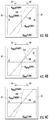
- FIG. 4A illustrates an exemplary plot of a suitable transfer function that may be associated with a corresponding operating mode for controlling the movement of a work vehicle component in accordance with aspects of the present subject matter, particularly illustrating an exemplary transfer function for executing a balanced implement shake mode;
- FIG. 4B illustrates another exemplary plot of a suitable transfer function that may be associated with a corresponding operating mode for controlling the movement of a work vehicle component in accordance with aspects of the present subject matter, particularly illustrating an exemplary transfer function for executing a curl-biased implement shake mode;
- FIG. 4C illustrates a further exemplary plot of a suitable transfer function that may be associated with a corresponding operating mode for controlling the movement of a work vehicle component in accordance with aspects of the present subject matter, particularly illustrating an exemplary transfer function for executing a dump-biased implement shake mode;
- FIG. 5 illustrates yet another exemplary plot of a suitable transfer function that may be associated with a corresponding operating mode for controlling the movement of a work vehicle component in accordance with aspects of the present subject matter, particularly illustrating an exemplary transfer function for executing a precision movement mode:
- FIG. 6 illustrates another exemplary plot of suitable transfer functions that may be associated with corresponding operating modes for controlling the movement of a work vehicle component in accordance with aspects of the present subject matter, particularly illustrating exemplary transfer function for executing a balanced implement shake mode according to different aggressiveness settings for the operating mode;
- FIG. 7 illustrates an exemplary plot of both lever position and flow rate versus time, particularly illustrating an example of the activation of an implement shake mode upon recognizing a given pattern of lever movements relative to a pre-defined lever movement range;
- FIG. 8 illustrates a flow diagram of one embodiment of a method for controlling the operation of a work vehicle in accordance with aspects of the present subject matter.
- the present subject matter is directed to systems and methods for controlling the operation of a work vehicle.
- the disclosed system and method may be used to control the movements of an implement of a work vehicle, such as the bucket on a front loader, based on operator input received from a control lever.
- the implement movement may be controlled within a plurality of different operating modes (e.g., one or more implement shake modes and/or one or more precision movement modes), with each operating mode being associated with a unique transfer function or control curve that correlates the position of the control lever to the flow rate of the hydraulic fluid supplied to an actuator configured to move the implement.
- each operating mode may be associated with or assigned to a specific range of lever positions or “lever movement ranges” defined within or across the control lever's overall travel range.
- the transfer function being utilized for correlating the lever position to the flow rate may be switched from the system's default or normal transfer function to the transfer function associated with such lever movement range, thereby allowing the movement of the implement to be controlled in accordance with the selected operating mode.
- FIG. 1 illustrates a side view of one embodiment of a work vehicle 10 .
- the work vehicle 10 is configured as a wheel loader.
- the work vehicle 10 may be configured as any other suitable work vehicle known in the art, such as any other work vehicle including movable loader arms (e.g., any other type of front loader, such as skid steer loaders, backhoe loaders, compact track loaders and/or the like).
- the work vehicle 10 includes a pair of front wheels 12 , a pair or rear wheels 14 and a chassis 16 coupled to and supported by the wheels 12 , 14 .
- An operator's cab 18 may be supported by a portion of the chassis 16 and may house various control or input devices (e.g., levers, pedals, control panels, buttons and/or the like) for permitting an operator to control the operation of the work vehicle 10 .
- the work vehicle 10 may include one or more control levers 20 for controlling the operation of one or more components of a lift assembly 22 of the work vehicle 10 .
- the lift assembly 22 may include a pair of loader arms 24 (one of which is shown) extending lengthwise between a first end 26 and a second end 28 , with the first ends 26 of the loader arms 24 being pivotally coupled to the chassis 16 and the second ends 28 of the loader arms 24 being pivotally coupled to a suitable implement 30 of the work vehicle. (e.g., a bucket, fork, blade, and/or the like).
- the lift assembly 22 also includes a plurality of actuators for controlling the movement of the loader arms 24 and the implement 30 .
- the lift assembly 22 may include a pair of hydraulic lift cylinders 32 (one of which is shown) coupled between the chassis 16 and the loader arms 24 for raising and lowering the loader arms 24 relative to the ground and a pair of hydraulic tilt cylinders 34 (one of which is shown) for tilting or pivoting the implement 30 relative to the loader arms 24 (e.g., between dump and curl positions).
- each tilt cylinder 34 may, for example, be coupled to the implement 30 via a linkage or lever arm 36 .
- extension or retraction of the tilt cylinders 34 may result in the lever arm 36 pivoting about a given pivot point to tilt the implement 30 relative to the loader arms 24 .
- the configuration of the work vehicle 10 described above and shown in FIG. 1 is provided only to place the present subject matter in an exemplary field of use.
- the present subject matter may be readily adaptable to any manner of work vehicle configuration.
- the work vehicle 10 was described above as including a pair of lift cylinders 32 and a pair of tilt cylinders 34 .
- the work vehicle 10 may, instead, include any number of lift cylinders 32 and/or tilt cylinders 24 , such as by only including a single lift cylinder 32 for controlling the movement of the loader arms 24 and/or a single tilt cylinder 34 for controlling the movement of the implement 30 .
- the input device is configured as a control lever (e.g., lever 20 of FIG. 1 ), which, as used herein, generally refers to any suitable input device configured to be moved or pivoted across a range of positions (e.g., including joysticks and similar input devices).
- the control lever 20 will generally be described with reference to providing operator inputs for controlling the operation of the tilt cylinders 34 , thereby allowing the operator to control the tilting or movement of the implement 30 relative to the loader arms 24 .
- the control lever 20 may generally be configured to control any suitable component(s) of the work vehicle 10 , such as the lift cylinders 32 .
- the control lever 20 has an overall travel range 50 including a plurality of lever positions defined between a first maximum position (indicated by line 52 ) and a second maximum position (indicated by line 54 ). Additionally, the travel range 50 for the control lever 20 may be centered or defined relative to a central lever position (indicated by line 56 ). In several embodiments, a neutral position range 58 for the control lever 20 may be defined relative to the center lever position 56 . As is generally understood, the amount or range of lever positions included within the neutral position range 58 generally corresponds to the “neutral position” for the control lever 20 at which the control output is equal to zero or is otherwise associated with the operator not commanding movement of the implement 30 .
- the neutral position range 58 may generally vary depending on the lever configuration and/or the configuration of the associated hydraulic/control system.
- the neutral position range 58 may span a given angular range of lever positions centered relative to the center lever position 56 , such as a range of lever positions equal to about 1% to about 10% of the overall travel range 50 for the lever 20 .
- the neutral position range 58 may only encompass the center lever position 56 such that the control lever 20 is only considered to be in “neutral” when disposed at the center lever position 56 .
- movement of the control lever 20 from a position within the neutral position range 58 in a first direction (indicated by arrow 60 in FIG. 2 and also referred to herein as the “dumping direction”) towards the first maximum position 52 may, for example, result in the flow rate of hydraulic fluid to one end of the tilt cylinders 34 being increased from a minimum flow towards a maximum flow according to an applicable transfer function correlating the lever position to the flow rate, thereby allowing the implement 30 to be tilted in a corresponding direction (e.g., towards a full dump position) at varying rates.
- movement of the control lever 20 from a position within the neutral position range 58 in a second direction (indicated by arrow 62 in FIG. 2 and also referred to herein as the “curling direction”) towards the second maximum position 54 may, for example, result in the flow rate of hydraulic fluid to the opposed end of the tilt cylinders 34 being increased from a minimum flow towards a maximum flow according to the applicable transfer function, thereby allowing the implement 30 to be tilted in an opposite direction (e.g., towards a fully curled position) at varying rates.
- a controller of the disclosed system may be configured to monitor the position of the control lever 20 relative to one or more lever movement ranges defined within or across the overall travel range 50 for the lever 20 .
- each lever movement range may correspond to a sub-range or subset of the full range of lever positions defined across the travel range 50 .
- the controller may be configured to monitor the movement of the control lever 20 to detect when the operator has moved the lever 20 relative to one of the lever movement ranges according to a predetermined or recognizable pattern.
- the controller may be configured to switch to a new or adjusted transfer function associated with such lever movement range for correlating the lever positions to resulting flow rates. For instance, the controller may be configured to monitor the lever movement and determine when the operator has moved the control lever back and forth across a specific lever movement range a threshold number of times (e.g., two or more times) within a given time period (e.g., a period of 1-2 seconds).
- a threshold number of times e.g., two or more times
- the detection of this particular pattern of movements relative to the associated lever movement range may then be interpreted by the controller as an indication that the operator desires to perform a certain implement movement (e.g., bucket shaking) or that the operator desires to control the movement of the implement 30 according to a particular operating mode (e.g., an implement shake mode or a precision movement mode).
- the controller may then access a predetermined transfer function associated with the lever movement range to allow the operation of the hydraulic system to be adjusted to provide the desired performance based on the desired implement movement and/or the desired mode of operation, such as by allowing for a more aggressive relationship between the lever position and the flow rate of hydraulic fluid to the tilt cylinders 34 to provide quicker responses to lever movements when rapid shaking of the implement 30 is desired.
- first lever movement range 70 extends across a range of lever positions defined between the first maximum position 52 and the neutral position range 58 , with such movement range 70 being bounded by a first max range position (indicated by line 70 A) and a first min range position (indicated by line 70 B).
- the second lever movement range 72 extends across a range of lever positions defined between the second maximum position 54 and the neutral position range 58 , with such movement range 72 being bounded by a second max range position (indicated by line 72 A) and a second min range position (indicated by line 72 B).
- the first and second lever movement ranges 70 , 72 correspond to non-overlapping lever position ranges and, thus, do not include any overlapping lever positions. Additionally, as shown in FIG.
- the third lever movement range 74 extends across a range of lever positions defined between the first and second maximum positions 52 , 54 that spans across the neutral position range 58 , with such movement range 74 being bounded by a third max range position (indicated by line 74 A) and a third min range position (indicated by line 74 B). As shown in the illustrated embodiment, the third lever movement range 74 overlaps portions of the first and second movement ranges 70 , 72 . As such, the first and third lever movement ranges 70 , 74 and the second and third lever movement ranges 72 , 74 include or incorporate overlapping lever position ranges.
- lever movement ranges 70 , 72 , 74 shown in FIG. 2 are simply provided as examples of suitable sub-ranges or lever position subsets that can be defined across the travel range 50 of the control lever 20 .
- the lever movement ranges may span across or encompass any other range of lever positions included within the overall travel range 50 .
- each lever movement range may be defined relative to the other movement ranges in any suitable manner, such as by selecting the lever movement ranges such that all of the ranges include overlapping lever positions or by selecting the lever movement ranges such that all of the ranges correspond to non-overlapping position ranges.
- any other suitable number of individual lever movement ranges may be defined across the travel range 50 for the control lever 20 , such as less than three lever movement ranges (e.g., two lever movement ranges) or greater than three lever movement ranges (e.g., four or more lever movement ranges).
- a suitable position sensor 80 may be provided in operative association with the control lever 20 to allow the position of the lever 20 to be tracked or monitored across its travel range 50 (and relative to the various lever movement ranges 70 , 72 , 74 ).
- a sensor 80 may be provided in operative association with the control lever 20 that detects the angular position of the lever 20 relative to a reference point, thereby allowing the position of the lever 20 across its travel range 50 to be accurately monitored as the lever 20 is being manipulated by the operator.
- FIG. 3 a schematic diagram of one embodiment of a system 100 for controlling the operation of a work vehicle is illustrated in accordance with aspects of the present subject matter.
- the system 100 will be described herein with reference to the work vehicle 10 shown and described above with reference to FIG. 1 .
- the disclosed system 100 may be utilized to control the operation of any work vehicle having any suitable vehicle configuration.
- the system 100 may generally include a controller 102 configured to electronically control the operation of one or more components of the work vehicle 10 , such as the various hydraulic components of the work vehicle 10 (e.g., the lift cylinders 32 and the tilt cylinders 34 ).
- the controller 102 may comprise any suitable processor-based device known in the art, such as a computing device or any suitable combination of computing devices.
- the controller 102 may include one or more processor(s) 104 and associated memory device(s) 106 configured to perform a variety of computer-implemented functions.
- processor refers not only to integrated circuits referred to in the art as being included in a computer, but also refers to a controller, a microcontroller, a microcomputer, a programmable logic controller (PLC), an application specific integrated circuit, and other programmable circuits.
- PLC programmable logic controller
- the memory device(s) 106 of the controller 102 may generally comprise memory element(s) including, but not limited to, computer readable medium (e.g., random access memory (RAM)), computer readable non-volatile medium (e.g., a flash memory), a floppy disk a compact disc-read only memory (CD-ROM), a magneto-optical disk (MOD), a digital versatile disc (DVD) and/or other suitable memory elements.
- Such memory device(s) 106 may generally be configured to store suitable computer-readable instructions that, when implemented by the processor(s) 104 , configure the controller 102 to perform various computer-implemented functions, such as by performing one or more aspects of the method 200 described below with reference to FIG. 8 .
- the controller 102 may also include various other suitable components, such as a communications circuit or module, one or more input/output channels, a data/control bus and/or the like.
- controller 102 may correspond to an existing controller of the work vehicle 10 or the controller 102 may correspond to a separate processing device.
- the controller 102 may form all or part of a separate plug-in module that may be installed within the work vehicle 10 to allow for the disclosed system and method to be implemented without requiring additional software to be uploaded onto existing control devices of the vehicle 10 .
- the controller 102 may be configured to be coupled to suitable components for controlling the operation of the various actuators 32 , 34 of the work vehicle 10 .
- the controller 102 may be communicatively coupled to suitable valves 108 , 110 (e.g., solenoid-activated valves) configured to control the supply of hydraulic fluid to each lift cylinder 32 (only one of which is shown in FIG. 3 ).
- the system 100 may include a first lift valve 108 for regulating the supply of hydraulic fluid to a cap end 112 of each lift cylinder 32 .
- the system 100 may include a second lift valve 110 for regulating the supply of hydraulic fluid to a rod end 114 of each lift cylinder 32 .
- the controller 102 may be communicatively coupled to suitable valves 116 , 118 (e.g., solenoid-activated valves) configured to regulate the supply of hydraulic fluid to each tilt cylinder 34 (only one of which is shown in FIG. 3 ).
- suitable valves 116 , 118 e.g., solenoid-activated valves
- the system 100 may include a first control valve 116 for regulating the supply of hydraulic fluid to a cap end 120 of each tilt cylinder 34 and a second control valve 118 for regulating the supply of hydraulic fluid to a rod end 122 of each tilt cylinder 34 .
- hydraulic fluid may be transmitted to the PRVs 108 , 110 , 116 , 118 from a fluid tank 124 mounted on and/or within the work vehicle 10 (e.g., via a pump (not shown)).
- the controller 102 may then be configured to control the operation of each valve 108 , 110 , 116 , 118 in order to control the flow rate of hydraulic fluid supplied to each of the cylinders 32 , 34 .
- the controller 102 may be configured to transmit suitable control commands to the lift valves 108 , 110 in order to regulate the flow of hydraulic fluid supplied to the cap and rod ends 112 , 114 of each lift cylinder 32 , thereby allowing for control of a stroke length 126 of the piston rod associated with each cylinder 32 .
- control commands may be transmitted from the controller 102 to the control valves 116 , 118 in order to control a stroke length 128 of the tilt cylinders 34 .
- the controller 102 may, in turn, be configured to automatically control the manner in which the implement 30 is pivoted or tilted relative to the loader arms 24 , thereby allowing the controller 102 to control orientation of the implement 30 relative to the ground.
- the controller 102 may be communicatively coupled to one or more input devices 130 for providing operator inputs to the controller 102 .
- Such input device(s) 130 may generally correspond to any suitable input device(s) or human-machine interface(s) (e.g., a control panel, one or more buttons, levers, and/or the like) housed within the operator's cab 18 that allows for operator inputs to be provided to the controller 102 .
- the input device(s) 130 may include one or more control levers (e.g., the control lever 20 described above with reference to FIG.
- the operator may be allowed to move a control lever 20 forward or backward across its travel range 50 to indicate his/her desire to pivot or tilt the implement 30 relative to the loader arms 24 in one direction or the other (e.g., in a dumping direction or a curling direction).
- the input device(s) 130 may also include a suitable interface (e.g., a touch-screen display, buttons, knobs, and/or the like) to allow the operator to provide inputs associated with the aggressiveness of the transfer function being used to correlate the operator inputs provided via the control lever 20 to the control signals transmitted to the valve(s) 116 , 118 for adjusting the flow rate to the associated tilt cylinders 34 .
- a suitable interface e.g., a touch-screen display, buttons, knobs, and/or the like
- the operator may be allowed to select an aggressiveness setting (e.g., high/medium/low) when moving the implement 30 within a given operating mode to fine tune the responsiveness of the tilt cylinders 34 to the operator-initiated movements of the control lever 20 .
- controller 102 may also be communicatively coupled to one or more sensors for monitoring one or more operating parameters of the work vehicle 10 .
- the controller 102 may be coupled to one or more position sensors 80 for monitoring the position of the control lever 20 .
- the controller 102 may track the position of the control lever 20 as it is being manipulated by the operator. Based on the appropriate transfer function being applied, the controller 102 may then correlate the position of the control lever 20 to an associated output or control signal for controlling the operation of the appropriate valve(s) 108 , 110 , thereby resulting in a corresponding flow rate of hydraulic fluid being supplied to the tilt cylinders 34 .
- the memory 106 of the controller 102 may be configured to store information accessible to the processor(s) 104 , including data that can be retrieved, manipulated, created and/or stored by the processor(s) 104 and instructions that can be executed by the processor(s) 104 .
- the data may be stored in one or more databases.
- the memory 106 may include a movement range database for storing data associated with the various different lever movement ranges defined for the control lever 20 . For example, as indicated above with reference to FIG.
- the travel range 50 for the control lever 20 may be sub-divided into a plurality of lever movement ranges (e.g., the first, second, and third lever movement ranges 70 , 72 , 74 ), with each range spanning a different sub-range or subset of the lever positions defined across the travel range 50 .
- the controller 102 may track such lever movements relative to the pre-defined lever movement ranges to determine when the operator is actuating the control lever 20 across or relative to a given movement range.
- the memory 106 of the controller 102 may also include an operating mode database storing data associated with the various different operating modes of the work vehicle.
- the controller may be configured to execute various operating modes associated with controlling the movement of the implement 30 , such as one or more implement shake modes, one or more precision movement modes, and/or the like.
- each individual operating mode may be associated with one of the lever movement ranges defined for the control lever 20 as well as activation pattern defining a specific pattern of lever movements that must be performed relative to the associated lever movement range for activating the operating mode.
- each of the lever movement ranges 70 , 72 , 74 may be assigned to a particular operating mode of the work vehicle.
- each operating mode may also be associated with a unique transfer function that correlates the movement of the control lever 20 to the flow rate of the hydraulic fluid to be supplied to the tilt cylinders 34 .
- the operating mode database within the controller's memory 106 may store such transfer functions in association with their respective operating modes. For instance, a more aggressive transfer function(s) may be associated with the implement shake mode(s) while a less aggressive transfer function(s) may be associated with the precision movement mode(s).
- the instructions stored within the memory 106 of the controller 102 may be executed by the processor(s) 104 to implement a mode selection/activation module.
- the mode selection/activation module may be configured to monitor the movement of the control lever 20 relative to the pre-defined lever movement ranges to determine when the operator has moved the control lever 20 across or relative to one of the lever movement ranges according to required activation pattern (e.g., movement back and forth across the lever movement range a threshold number of times within a given time period). When such a determination is made, the controller 102 may be configured to activate the operating mode associated with the relevant lever movement range.
- the controller 102 may access the operating mode database within its memory 106 to determine the appropriate transfer function to be applied for the selected operating mode.
- the referenced transfer function may then be utilized to generate control signals for controlling the associated valve(s) 116 , 118 based on the position of the control lever 20 , thereby allowing the controller to regulate the flow rate to the tilt cylinders 34 in accordance with the inputs provided by the operator via the lever 20 .
- FIGS. 4A-4C various example plots of suitable transfer functions that may be associated with corresponding operating modes for controlling the movement of the implement 30 of the work vehicle 10 are illustrated in accordance with aspects of the present subject matter.
- the illustrated plots provide example transfer functions for executing different implement shake modes, such as a balanced implement shake mode ( FIG. 4A ), a curl-biased shake mode ( FIG. 4B ), and a dump-biased shake mode ( FIG. 4C ), relative to a default or baseline transfer function (indicated by solid line 140 in FIGS. 4A-4C ) that is otherwise utilized during normal operation of the work vehicle 10 .
- a balanced implement shake mode FIG. 4A
- FIG. 4B curl-biased shake mode
- FIG. 4C dump-biased shake mode
- control lever position (X) is plotted along the horizontal axis across the travel range 50 ( FIG. 2 ) defined between the first and second maximum positions 52 , 54 (with the neutral position range being defined at the origin) and the flow rate (Q) to the tilt cylinders 34 is plotted along the vertical axis, with the flow rate ranging from zero at the origin to maximum flow rates for moving the implement 30 in both the dumping direction (Q MAX (dump)) and the curling direction (Q MAX (curl)).
- the baseline transfer function 140 when operating in the default or normal operating mode, is adapted such that a linear relationship exists between the lever position and the flow rate of hydraulic fluid supplied to the tilt cylinders 34 .
- the flow rate increases at a constant rate until the maximum flow (Q MAX (dump)) is reached.
- the control lever 20 is moved from the neutral position towards the second maximum position 54 in the second direction 62 to actuate the implement 30 toward its curl position, the flow rate increases at a constant rate until the maximum flow (Q MAX (curl)) is reached.
- one or more of the implement shake modes may be executed to provide increased responsiveness to the operator-initiated movements of the control lever 20 .
- FIG. 4A illustrates an adjusted transfer function (indicated by dashed line 142 ) for executing a balanced implement shake mode in which the flow rate to the tilt cylinders 34 is increased much more rapidly to the maximum flow rate in response to movements of the control lever 20 in both the first and second directions 60 , 62 .
- the adjusted transfer function 142 of FIG. 4A provides a stepwise increase in the flow rate immediately upon moving the control lever 20 out of the neutral position.
- the flow rate is initiated at a base flow rate (Q BASE (dump)) that is greater than zero (e.g., a flow rate ranging from 25% to 75% of the maximum flow rate) and is then increased at a relatively high rate over a shorter range of lever positions until the maximum flow (Q MAX (dump)) is reached.
- Q BASE a base flow rate
- Q MAX a relatively high rate over a shorter range of lever positions until the maximum flow
- the flow rate is initiated at a base flow rate (Q BASE (curl)) that is greater than zero (e.g., a flow rate ranging from 25% to 75% of the maximum flow rate) and is then increased at a relatively high rate over a shorter range of lever positions until the maximum flow (Q MAX (curl)) is reached.
- Q BASE a flow rate ranging from 25% to 75% of the maximum flow rate
- Q MAX a relatively high rate over a shorter range of lever positions until the maximum flow
- FIG. 4B illustrates an adjusted transfer function (indicated by dashed line 144 ) for executing a curl-biased implement shake mode in which the flow rate to the tilt cylinders 34 is increased much more quickly to the maximum flow rate in response to movements of the control lever 20 in the curling or second direction 62 .
- the transfer function 144 of FIG. 4B provides a stepwise increase in the flow rate immediately upon moving the control lever 20 out of the neutral position toward second maximum position 54 .
- the flow rate is initiated at a base flow rate (Q BASE (curl)) that is greater than zero (e.g., a flow rate ranging from 25% to 75% of the maximum flow rate) and is then increased at a relatively high rate over a shorter range of lever positions until the maximum flow (Q MAX (curl)) is reached.
- Q BASE base flow rate
- Q MAX maximum flow rate
- the transfer function 144 provides a much more aggressive relationship between the lever position and flow rate in the second direction 62 as compared to the baseline transfer function 140 .
- the flow rate increases linearly from zero.
- the rate of increase in the flow rate provided by the adjusted transfer function 144 may be greater than the baseline transfer function 140 to provide increased responsiveness across a shorter range of lever positions when actuating the implement 30 in the dumping or first direction 60 .
- FIG. 4C illustrates an adjusted transfer function (indicated by dashed line 146 ) for executing a dump-biased implement shake mode in which the fluid rate to the tilt cylinders 34 is increased much more quickly to the maximum rate in response to movements of the control lever 20 in the dumping or first direction 60 .
- the adjusted transfer function 146 of FIG. 4C provides a stepwise increase in the flow rate immediately upon moving the control lever 20 out of the neutral position toward the first maximum position 52 .
- the flow rate is initiated at a base flow rate (Q BASE (dump)) that is greater than zero (e.g., a flow rate ranging from 25% to 75% of the maximum flow rate) and is then increased at a relatively high rate over a shorter range of lever positions until the maximum flow (Q MAX (dump)) is reached.
- Q BASE a base flow rate
- Q MAX a relatively high rate over a shorter range of lever positions until the maximum flow
- the transfer function provides a much more aggressive relationship between the lever position and flow rate in the first direction 60 as compared to the baseline transfer function 140 .
- the flow rate increases linearly from zero.
- the rate of increase in the flow rate provided by the transfer function 146 may be greater than the baseline transfer function 140 to provide increased responsiveness across a shorter range of lever positions when actuating the implement in the curling or second direction 62 .
- each of the various implement shake modes described above may be assigned to a given lever movement range to allow the operator to select or activate one of such operating modes based on movement of the control lever 20 across the associated lever movement range according to the required activation pattern.
- the first lever movement range 70 may be associated with selection of the dump-biased implement shake mode of FIG. 4C
- the second lever movement range 72 may be associated with the curl-biased implement shake mode of FIG. 4B
- the third lever movement range 74 may be associated with the balanced implement shake mode of FIG. 4C .
- the controller 102 may activate the dump-biased implement shake mode or the curl-biased implement shake mode when it is detected that the operator has moved the control lever 20 back and forth across the first lever movement range 70 or the second lever movement range 72 , respectively, a threshold number of times within a given time period.
- the controller 102 may activate the balanced implement shake mode when it is detected that the operator has moved the control lever 20 back and forth across the third lever movement range 74 a threshold number of times within a given time period.
- FIG. 5 another example plot of a suitable transfer function that may be associated with a corresponding operating mode for controlling the movement of the implement 30 of the work vehicle 10 is illustrated in accordance with aspects of the present subject matter.
- the illustrated plot provides an example adjusted transfer function (indicated by dashed line 150 ) for executing a precision movement mode when it is desired to very precisely and accurately control the movement of the implement 30 .
- FIG. 5 illustrates the same baseline transfer function 140 as that described above with reference to FIGS. 4A-4C .
- the adjusted transfer function 150 is shown as providing a linear relationship between the lever position and the flow rate of hydraulic fluid to the tilt cylinders 34 .
- the adjusted transfer function 150 increases the flow rate at a much slower rate. Specifically, as the control lever 20 is moved from the neutral position in the first direction 60 towards the first maximum position 52 to actuate the implement 30 toward its dump position, the flow rate increases at a constant rate until the first maximum position 52 is reached (and without reaching the maximum flow rate (Q MAX (dump))). Similarly, as the control lever 20 is moved from the neutral position in the second direction 62 towards the second maximum position 54 to actuate the implement 30 toward its curl position, the flow rate increases at a constant rate until the second maximum position 54 is reached (and without reaching the maximum flow rate (Q MAX (curl))). Thus, as compared to the baseline transfer function 140 , the adjusted transfer function 150 provides for a significantly less aggressive relationship between lever position and flow rate to allow for more precise control of the resulting movements of the implement 30 .
- the precision movement mode may be assigned to a given lever movement range to allow the operator to select or activate such operating mode based on movement of the control lever 30 across the associated lever movement range according to the required activation pattern. It should also be appreciated that, similar to the transfer functions 142 , 144 , 146 described above, multiple different precision movement modes may be executed for the controller 102 . For instance, FIG. 5 provides an example transfer function for implementing a more balanced precision movement mode.
- suitable transfer functions may also be provided to implement a dump-biased precision movement mode in which a less aggressive relationship is defined between lever position and flow rate when moving the control lever 20 in the dumping or first direction 60 and/or a curl-biased precision movement mode in which a less aggressive relationship is defined between lever position and flow rate when moving the control lever 20 in the curling or second direction 62 .
- FIG. 6 another example plot of suitable transfer functions that may be associated with corresponding operating modes for controlling the movement of the implement 30 of the work vehicle 10 are illustrated in accordance with aspects of the present subject matter.
- the illustrated plot provides example adjusted transfer functions 142 A, 142 B, 142 C for executing several different balanced implement shake modes, with each operating mode being associated with a different aggressiveness setting.
- the operator may be allowed to select a given aggressiveness setting (e.g., high/medium/low).
- the various transfer functions 142 A, 142 B, 142 C correspond to high/medium/low aggressiveness settings for the transfer function 142 A associated with the balanced implement shake mode described above with reference to FIG.
- a first transfer function 142 A is defined that provides a highly aggressive relationship between lever position and flow rate when moving the control lever 20 in both the dumping and curling directions 60 , 62 while a second transfer function 142 B is defined that provides a much less aggressive relationship between lever position and flow rate when moving the control lever 20 in such directions 60 , 62 than the first transfer function 142 B (while still being more aggressive than the baseline transfer function 140 ).
- a third transfer function 142 C is defined that provides an intermediate level of aggressiveness between lever position and flow rate when moving the control lever 20 in both the dumping and curling directions 60 , 62 (e.g., as compared to the first and second transfer functions 142 A, 142 B).
- the operator may select between the different implement shake modes (e.g., the balanced shaking mode, the dump-biased shaking mode, and the curl-biasing shaking mode) by moving the control lever 20 across the associated lever movement range (e.g., the first, second, or third lever movement range 70 , 72 , 74 ) and may further select an aggressiveness setting for the selected operating mode (e.g., high/medium/low), thereby providing the operator with nine different options for selecting a transfer function to that meets the operator's performance requirements.
- the different implement shake modes e.g., the balanced shaking mode, the dump-biased shaking mode, and the curl-biasing shaking mode
- an aggressiveness setting for the selected operating mode e.g., high/medium/low
- FIGS. 4-6 provide various examples of suitable transfer functions that may be utilized when controlling the movement of the implement 30 within a given non-default operating mode. It should be appreciated that, once one of such operating modes has been activated (e.g., by detecting the required movement pattern by the control lever 20 relative to the associated lever movement range), the operating mode may, for example, by automatically de-activated by the controller 102 upon detection of a given trigger event(s), thereby returning the control of the various hydraulic components back to their normal or default operating mode (e.g., operation using the baseline transfer function 140 described above).
- the controller 102 may, for example, by automatically de-activated by the controller 102 upon detection of a given trigger event(s), thereby returning the control of the various hydraulic components back to their normal or default operating mode (e.g., operation using the baseline transfer function 140 described above).
- Such trigger event(s) for deactivating a given operating mode may, for example, include, but are not limited to, detection by the controller 102 that the control lever 20 has been maintained at the neutral position for longer than a predetermined time period, detection by the controller 102 that the control lever 20 at another position for longer than a predetermined time period (e.g., the first or second maximum position 52 , 54 ), and/or detection by the controller 102 that the lever oscillation frequency relative to a given lever movement range has dropped below a predetermined threshold (e.g., detection that the operator is no longer actuating the control lever 20 in quick back and forth motions).
- a predetermined time period e.g., the first or second maximum position 52 , 54
- lever position i.e., the top graph
- flow rate percentage i.e., the bottom graph
- the control lever 20 is being continuously moved back and forth by the operator across the lever's neutral position range (identified within the plot at a lever position of zero) between a maximum lever position (indicated by line 176 ) and a minimum lever position (indicated by line 178 ).
- a lever movement range 180 is defined for the control lever 20 between a first joystick position (indicated by line 182 ) and a second joystick position (indicated by line 184 ).
- the control lever 20 is being actuated by the operator back and forth across the lever movement range 180 .
- the controller 102 recognizes (e.g., at time T 1 ) that the control lever 20 has been moved across such movement range 180 according to the associated activation pattern (e.g., movement back and forth across the range 180 at least twice within a time period of less than one second).
- the implement shake mode is automatically activated by the controller 102 such that a new, more aggressive transfer function is applied to the lever position inputs.
- the more aggressive transfer function results in rapid increases in the flow rate as the lever position is moved back and forth between the maximum and minimum lever positions 176 , 178 , thereby allowing for more effective shaking of the implement 30 .
- the controller 102 may be configured to maintain the flow rate constant as the operator moves the control lever 20 across its neutral position range while operating within the implement shake mode. For instance, as shown in FIG. 7 , the control lever 20 is moved across its neutral position range at various different time periods, such as the time period defined between time T 2 and time T 3 and the time period defined between time T 4 and time T 5 . Additionally, as shown in FIG. 7 , the flow rate is maintained constant across such time periods. For example, upon entering the neutral position range, the controller may be configured to hold or fix the commanded flow rate at the flow rate commanded immediately prior to entering the neutral position range.
- the controller 102 may update the commanded flow rate based on the applicable transfer function, such as by commanding a stepwise change in the flow rate. It should be appreciated that, by maintaining the commanded flow rate constant across the neutral position range, higher implement acceleration values may be achieved during the shaking procedure as the lever 20 passes through such neutral range.
- FIG. 8 a flow diagram of one embodiment of a method 200 for controlling the operation of a work vehicle is illustrated in accordance with aspects of the present subject matter.
- the method 200 will be described herein with reference to the system 100 described above with reference to FIG. 3 .
- the disclosed method 200 may be implemented within any other system having any other suitable system configuration.
- FIG. 3 depicts steps performed in a particular order for purposes of illustration and discussion, the methods discussed herein are not limited to any particular order or arrangement.
- steps of the methods disclosed herein can be omitted, rearranged, combined, and/or adapted in various ways without deviating from the scope of the present disclosure.
- the method 200 may include initially controlling the operation of an actuator based at least in part on a baseline transfer function correlating a position of an input device to a flow rate of fluid supplied to the actuator.
- a baseline transfer function correlating a position of an input device to a flow rate of fluid supplied to the actuator.
- the operation of the tilt cylinders 34 may be controlled by the controller 102 based on a default or baseline transfer function that correlates the operator-controlled position of the control lever to the flow rate of the fluid being supplied to the tilt cylinders 34 .
- the method 200 may include monitoring the movement of the input device relative to first and second movement ranges defined across portions of a range of positions for the input device.
- the overall range of positions 50 for the control lever 20 may be subdivided into two or more lever movement ranges, with each lever movement range corresponding to a different sub-range or subset of lever positions across the overall range of lever positions 50 .
- the various lever movement ranges may correspond to overlapping lever ranges and/or non-overlapping lever ranges.
- the controller 102 may be configured to monitor the movement of the control lever 20 relative to the lever movement ranges.
- the method 200 includes detecting a pattern of input device movements relative to one of the first movement range or the second movement range.
- the controller 102 may be configured to detect when the operator moves the lever 20 according to a predetermined pattern of lever movements relative to one of the lever movement ranges. For instance, the controller 102 may be configured to detect when the control lever 20 is moves back and forth across a given lever movement range a minimum number of times across a given time period.
- the method 200 includes selecting an adjusted transfer function for correlating the position of the input device to the flow rate from one of a first adjusted transfer function associated with the first movement range or a second adjusted transfer function associated with the second movement range based on whether the detected pattern of input device movements was relative to the first movement range or the second movement range.
- each lever movement range may be associated with a transfer function that differs from both the baseline transfer function and the transfer functions associated with the other lever movement ranges.
- the manner in which the tilt cylinder is being controlled may be adjusted in accordance with the operating mode with which the selected transfer function is associated.
- the method includes controlling the operation of the actuator based at least in part on the adjusted transfer function to control movement of a component of the work vehicle coupled to the actuator.
- the controller 102 may be configured to utilize the transfer function to control the movements of the implement 30 .
- the selected transfer function may be used to convert the lever position inputs provided by the operator to control outputs for controlling the flow rate of the hydraulic fluid supplied to the tilt cylinders 34 , thereby allowing the movement of the implement 30 to be automatically controlled by the controller 102 .
- the steps of the method 200 are performed by the controller 102 upon loading and executing software code or instructions which are tangibly stored on a tangible computer readable medium, such as on a magnetic medium, e.g., a computer hard drive, an optical medium, e.g., an optical disc, solid-state memory, e.g., flash memory, or other storage media known in the art.
- a tangible computer readable medium such as on a magnetic medium, e.g., a computer hard drive, an optical medium, e.g., an optical disc, solid-state memory, e.g., flash memory, or other storage media known in the art.
- any of the functionality performed by the controller 102 described herein, such as the method 200 is implemented in software code or instructions which are tangibly stored on a tangible computer readable medium.
- the controller 102 loads the software code or instructions via a direct interface with the computer readable medium or via a wired and/or wireless network. Upon loading and executing such software code or instructions by the controller 102
- software code or “code” used herein refers to any instructions or set of instructions that influence the operation of a computer or controller. They may exist in a computer-executable form, such as machine code, which is the set of instructions and data directly executed by a computer's central processing unit or by a controller, a human-understandable form, such as source code, which may be compiled in order to be executed by a computer's central processing unit or by a controller, or an intermediate form, such as object code, which is produced by a compiler.
- the term “software code” or “code” also includes any human-understandable computer instructions or set of instructions, e.g., a script, that may be executed on the fly with the aid of an interpreter executed by a computer's central processing unit or by a controller.
Abstract
Description
Claims (20)
Priority Applications (1)
| Application Number | Priority Date | Filing Date | Title |
|---|---|---|---|
| US16/165,874 US10801182B2 (en) | 2018-10-19 | 2018-10-19 | System and method for controlling work vehicle operation based on multi-mode identification of operator inputs |
Applications Claiming Priority (1)
| Application Number | Priority Date | Filing Date | Title |
|---|---|---|---|
| US16/165,874 US10801182B2 (en) | 2018-10-19 | 2018-10-19 | System and method for controlling work vehicle operation based on multi-mode identification of operator inputs |
Publications (2)
| Publication Number | Publication Date |
|---|---|
| US20200123738A1 US20200123738A1 (en) | 2020-04-23 |
| US10801182B2 true US10801182B2 (en) | 2020-10-13 |
Family
ID=70278838
Family Applications (1)
| Application Number | Title | Priority Date | Filing Date |
|---|---|---|---|
| US16/165,874 Active 2039-04-09 US10801182B2 (en) | 2018-10-19 | 2018-10-19 | System and method for controlling work vehicle operation based on multi-mode identification of operator inputs |
Country Status (1)
| Country | Link |
|---|---|
| US (1) | US10801182B2 (en) |
Families Citing this family (2)
| Publication number | Priority date | Publication date | Assignee | Title |
|---|---|---|---|---|
| JP7312563B2 (en) * | 2019-02-19 | 2023-07-21 | 株式会社小松製作所 | Work machine control system and control method |
| WO2021247095A1 (en) * | 2020-06-03 | 2021-12-09 | Parker-Hannifin Corporation | Sensing and control of a rapidly-commanded hydraulic actuator |
Citations (22)
| Publication number | Priority date | Publication date | Assignee | Title |
|---|---|---|---|---|
| US5860231A (en) | 1996-04-30 | 1999-01-19 | Samsung Heavy Industries Co., Ltd. | Device and method for automatically vibrating working members of power construction vehicles |
| US20030097595A1 (en) * | 2000-10-23 | 2003-05-22 | Craig Partridge | Method and system for passively analyzing communication data based on frequency analysis of encrypted data traffic, and method and system for deterring passive analysis of communication data |
| US20040003977A1 (en) * | 2002-07-05 | 2004-01-08 | Peter Schiele | System and method for supplying cooling fluid for friction elements in automatic transmissions |
| US6725105B2 (en) | 2000-11-30 | 2004-04-20 | Caterpillar Inc | Bucket shakeout mechanism for electro-hydraulic machines |
| US20040209718A1 (en) * | 2001-10-22 | 2004-10-21 | Fumio Ishibashi | Hydraulic transmission vehicle |
| US20050203691A1 (en) | 2004-03-10 | 2005-09-15 | Volvo Construction Equipment Holding Sweden Ab | Automatic vibration device and method for use in construction equipment |
| US20050211528A1 (en) * | 2004-03-26 | 2005-09-29 | Yanming Hou | Power take-off control system and method |
| US20060110247A1 (en) * | 2004-11-24 | 2006-05-25 | General Electric Company | Pattern for the surface of a turbine shroud |
| US7114747B2 (en) | 2003-10-20 | 2006-10-03 | Cnh America Llc | Work vehicle stabilizer |
| US7117952B2 (en) | 2004-03-12 | 2006-10-10 | Clark Equipment Company | Automated attachment vibration system |
| US20080296032A1 (en) * | 2007-05-30 | 2008-12-04 | Kubota Corporation | Operating Apparatus for Work Vehicle |
| US20090084623A1 (en) * | 2007-09-28 | 2009-04-02 | Bombardier Recreational Products Inc. | Load sensor for a vehicle electronic stability system |
| US7571604B2 (en) | 2004-04-19 | 2009-08-11 | Volvo Contruction Equipment Ab | Method for shaking a work implement |
| US20100082192A1 (en) * | 2008-08-27 | 2010-04-01 | EcoMotors International | Hybrid Engine System |
| US7726125B2 (en) | 2007-07-31 | 2010-06-01 | Caterpillar Inc. | Hydraulic circuit for rapid bucket shake out |
| US20100186778A1 (en) * | 2009-01-23 | 2010-07-29 | Gregg Martin | Automated Wash System for Industrial Vehicles |
| US7866149B2 (en) | 2007-09-05 | 2011-01-11 | Caterpillar Inc | System and method for rapidly shaking an implement of a machine |
| US20110204712A1 (en) * | 2007-05-24 | 2011-08-25 | Nicolai Tarasinski | Electric Connection System |
| US8214097B2 (en) * | 1998-09-14 | 2012-07-03 | Paice Llc | Hybrid vehicles |
| US20140156129A1 (en) * | 2011-06-29 | 2014-06-05 | Toyota Jidosha Kabushiki Kaisha | Control device for vehicle drive device |
| US20140230785A1 (en) * | 2012-11-20 | 2014-08-21 | Komatsu Ltd. | Engine control apparatus and construction machine |
| US9085440B2 (en) | 2009-12-22 | 2015-07-21 | Doosan Infracore Co., Ltd. | Electronic hydraulic pressure control apparatus and method using variable behavior |
-
2018
- 2018-10-19 US US16/165,874 patent/US10801182B2/en active Active
Patent Citations (22)
| Publication number | Priority date | Publication date | Assignee | Title |
|---|---|---|---|---|
| US5860231A (en) | 1996-04-30 | 1999-01-19 | Samsung Heavy Industries Co., Ltd. | Device and method for automatically vibrating working members of power construction vehicles |
| US8214097B2 (en) * | 1998-09-14 | 2012-07-03 | Paice Llc | Hybrid vehicles |
| US20030097595A1 (en) * | 2000-10-23 | 2003-05-22 | Craig Partridge | Method and system for passively analyzing communication data based on frequency analysis of encrypted data traffic, and method and system for deterring passive analysis of communication data |
| US6725105B2 (en) | 2000-11-30 | 2004-04-20 | Caterpillar Inc | Bucket shakeout mechanism for electro-hydraulic machines |
| US20040209718A1 (en) * | 2001-10-22 | 2004-10-21 | Fumio Ishibashi | Hydraulic transmission vehicle |
| US20040003977A1 (en) * | 2002-07-05 | 2004-01-08 | Peter Schiele | System and method for supplying cooling fluid for friction elements in automatic transmissions |
| US7114747B2 (en) | 2003-10-20 | 2006-10-03 | Cnh America Llc | Work vehicle stabilizer |
| US20050203691A1 (en) | 2004-03-10 | 2005-09-15 | Volvo Construction Equipment Holding Sweden Ab | Automatic vibration device and method for use in construction equipment |
| US7117952B2 (en) | 2004-03-12 | 2006-10-10 | Clark Equipment Company | Automated attachment vibration system |
| US20050211528A1 (en) * | 2004-03-26 | 2005-09-29 | Yanming Hou | Power take-off control system and method |
| US7571604B2 (en) | 2004-04-19 | 2009-08-11 | Volvo Contruction Equipment Ab | Method for shaking a work implement |
| US20060110247A1 (en) * | 2004-11-24 | 2006-05-25 | General Electric Company | Pattern for the surface of a turbine shroud |
| US20110204712A1 (en) * | 2007-05-24 | 2011-08-25 | Nicolai Tarasinski | Electric Connection System |
| US20080296032A1 (en) * | 2007-05-30 | 2008-12-04 | Kubota Corporation | Operating Apparatus for Work Vehicle |
| US7726125B2 (en) | 2007-07-31 | 2010-06-01 | Caterpillar Inc. | Hydraulic circuit for rapid bucket shake out |
| US7866149B2 (en) | 2007-09-05 | 2011-01-11 | Caterpillar Inc | System and method for rapidly shaking an implement of a machine |
| US20090084623A1 (en) * | 2007-09-28 | 2009-04-02 | Bombardier Recreational Products Inc. | Load sensor for a vehicle electronic stability system |
| US20100082192A1 (en) * | 2008-08-27 | 2010-04-01 | EcoMotors International | Hybrid Engine System |
| US20100186778A1 (en) * | 2009-01-23 | 2010-07-29 | Gregg Martin | Automated Wash System for Industrial Vehicles |
| US9085440B2 (en) | 2009-12-22 | 2015-07-21 | Doosan Infracore Co., Ltd. | Electronic hydraulic pressure control apparatus and method using variable behavior |
| US20140156129A1 (en) * | 2011-06-29 | 2014-06-05 | Toyota Jidosha Kabushiki Kaisha | Control device for vehicle drive device |
| US20140230785A1 (en) * | 2012-11-20 | 2014-08-21 | Komatsu Ltd. | Engine control apparatus and construction machine |
Also Published As
| Publication number | Publication date |
|---|---|
| US20200123738A1 (en) | 2020-04-23 |
Similar Documents
| Publication | Publication Date | Title |
|---|---|---|
| EP2947209B1 (en) | Improved lift assembly for a work vehicle | |
| US8594896B2 (en) | Lift arm control system | |
| US10017912B2 (en) | Work vehicle with improved loader/implement position control and return-to-position functionality | |
| EP2543777B1 (en) | Damper operation control device for a work vehicle, and damper operation control method | |
| US8700271B2 (en) | Machine with four degrees of freedom implement control joystick and track type tractor using same | |
| US10801182B2 (en) | System and method for controlling work vehicle operation based on multi-mode identification of operator inputs | |
| US10385541B2 (en) | Work vehicle with improved loader/implement return position control | |
| CN107567517B (en) | System and method for positioning a lift arm on a power machine | |
| JP6957414B2 (en) | Work machine | |
| US20110088785A1 (en) | Safety feature for stuck valve | |
| US20130299266A1 (en) | Hydraulic Ride Control System with Manual Mode Safeguard | |
| US11261582B1 (en) | System and method for controlling hydraulic fluid flow within a work vehicle using flow control valves | |
| JP7284019B2 (en) | System and method for controlling bulldozer | |
| US11421401B2 (en) | System and method for controlling work vehicle implements during implement shake operations | |
| US11702819B2 (en) | Electrohydraulic implement control system and method | |
| US10597846B2 (en) | System and method for positioning a lift arm on a power machine | |
| US11732442B2 (en) | System and method for controlling the operation of a work vehicle to provide improved responsiveness when commanding implement movement | |
| US10392774B2 (en) | Position control system and method for an implement of a work vehicle | |
| US11549236B1 (en) | Work vehicle with improved bi-directional self-leveling functionality and related systems and methods | |
| US20220243425A1 (en) | System and method for controlling implement orientation of a work vehicle based on a modified error value | |
| US20220186469A1 (en) | System and method for controlling implement operation of a work vehicle using a speed-based parameter | |
| EP4174325A1 (en) | System and method for controlling hydraulic valve operation within a work vehicle | |
| EP4174326A1 (en) | System and method for controlling hydraulic valve operation within a work vehicle | |
| US11066810B2 (en) | Work vehicle and control method for work vehicle | |
| US11726611B2 (en) | Method and control unit for generating a control command to at least one actuator of an electrohydraulic machine |
Legal Events
| Date | Code | Title | Description |
|---|---|---|---|
| AS | Assignment |
Owner name: CNH INDUSTRIAL AMERICA LLC, PENNSYLVANIA Free format text: ASSIGNMENT OF ASSIGNORS INTEREST;ASSIGNORS:ESPINOSA, RAUL;WU, DUQIANG;SINGH, ADITYA;AND OTHERS;SIGNING DATES FROM 20181015 TO 20181016;REEL/FRAME:047238/0711 |
|
| FEPP | Fee payment procedure |
Free format text: ENTITY STATUS SET TO UNDISCOUNTED (ORIGINAL EVENT CODE: BIG.); ENTITY STATUS OF PATENT OWNER: LARGE ENTITY |
|
| STPP | Information on status: patent application and granting procedure in general |
Free format text: NOTICE OF ALLOWANCE MAILED -- APPLICATION RECEIVED IN OFFICE OF PUBLICATIONS |
|
| STPP | Information on status: patent application and granting procedure in general |
Free format text: PUBLICATIONS -- ISSUE FEE PAYMENT VERIFIED |
|
| STCF | Information on status: patent grant |
Free format text: PATENTED CASE |
|
| AS | Assignment |
Owner name: BLUE LEAF I.P., INC., DELAWARE Free format text: ASSIGNMENT OF ASSIGNORS INTEREST;ASSIGNOR:CNH INDUSTRIAL AMERICA LLC;REEL/FRAME:055343/0448 Effective date: 20210205 |
|
| MAFP | Maintenance fee payment |
Free format text: PAYMENT OF MAINTENANCE FEE, 4TH YEAR, LARGE ENTITY (ORIGINAL EVENT CODE: M1551); ENTITY STATUS OF PATENT OWNER: LARGE ENTITY Year of fee payment: 4 |