US1080098A - Submarine signaling. - Google Patents
Submarine signaling. Download PDFInfo
- Publication number
- US1080098A US1080098A US67285712A US1912672857A US1080098A US 1080098 A US1080098 A US 1080098A US 67285712 A US67285712 A US 67285712A US 1912672857 A US1912672857 A US 1912672857A US 1080098 A US1080098 A US 1080098A
- Authority
- US
- United States
- Prior art keywords
- water
- pressure
- plate
- ajutage
- submarine
- Prior art date
- Legal status (The legal status is an assumption and is not a legal conclusion. Google has not performed a legal analysis and makes no representation as to the accuracy of the status listed.)
- Expired - Lifetime
Links
- 230000011664 signaling Effects 0.000 title description 10
- XLYOFNOQVPJJNP-UHFFFAOYSA-N water Substances O XLYOFNOQVPJJNP-UHFFFAOYSA-N 0.000 description 23
- XEEYBQQBJWHFJM-UHFFFAOYSA-N Iron Chemical compound [Fe] XEEYBQQBJWHFJM-UHFFFAOYSA-N 0.000 description 6
- 230000002706 hydrostatic effect Effects 0.000 description 4
- 229910052742 iron Inorganic materials 0.000 description 3
- 239000002184 metal Substances 0.000 description 3
- 229910052751 metal Inorganic materials 0.000 description 3
- 230000035939 shock Effects 0.000 description 3
- 239000007787 solid Substances 0.000 description 3
- 229910000831 Steel Inorganic materials 0.000 description 2
- 230000003467 diminishing effect Effects 0.000 description 2
- 230000000694 effects Effects 0.000 description 2
- 230000001970 hydrokinetic effect Effects 0.000 description 2
- 239000010959 steel Substances 0.000 description 2
- 239000002023 wood Substances 0.000 description 2
- 230000002844 continuous effect Effects 0.000 description 1
- 238000010586 diagram Methods 0.000 description 1
- 239000012530 fluid Substances 0.000 description 1
- 238000011835 investigation Methods 0.000 description 1
- 239000000463 material Substances 0.000 description 1
- 238000000034 method Methods 0.000 description 1
- 238000012986 modification Methods 0.000 description 1
- 230000004048 modification Effects 0.000 description 1
- 230000000644 propagated effect Effects 0.000 description 1
Images
Classifications
-
- G—PHYSICS
- G10—MUSICAL INSTRUMENTS; ACOUSTICS
- G10K—SOUND-PRODUCING DEVICES; METHODS OR DEVICES FOR PROTECTING AGAINST, OR FOR DAMPING, NOISE OR OTHER ACOUSTIC WAVES IN GENERAL; ACOUSTICS NOT OTHERWISE PROVIDED FOR
- G10K11/00—Methods or devices for transmitting, conducting or directing sound in general; Methods or devices for protecting against, or for damping, noise or other acoustic waves in general
- G10K11/18—Methods or devices for transmitting, conducting or directing sound
- G10K11/26—Sound-focusing or directing, e.g. scanning
- G10K11/35—Sound-focusing or directing, e.g. scanning using mechanical steering of transducers or their beams
- G10K11/352—Sound-focusing or directing, e.g. scanning using mechanical steering of transducers or their beams by moving the transducer
Definitions
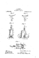
- Fig. 3 is a part section and side'elevation of one specific ,form or embodiment of. the invention, and-Figs. 4 and 5 similar views of other such forms. or modifications.
- A represents a plate of any material, such as wood or metal
- B a tube connected with a supply of water under pressure
- C a nozzle, which Iin Fig. 2 is provided with wide flanges giving it the form of a plate with a central orifice.' y
- the sudden checking of the issuing water by the vibrations of plate A produces a Water hammer effect, in the supply pipe, theham mer pressure in -pounds per square inch beingV about 50 times the velocity of the water in feet per second, so that it lis not difficult to ⁇ obtain 100 lbs. per square inch in Water shocks .that may be transmitted as a continuous sound through the water.
- the vibrations of the plate A or part corfound, as a result of my observaresponding thereto in a properly organized apparatus may be utilized to produce a succession of inechanicalblows upon such a body as a submarine bell; or the vibrations may be imparted to suitably designed and constructed diaphragms, or. utilized in other ways to secure a similar effect or'result.
- the numeral 2 designates an iron or steel cylinder having an.inlet 3 through whichy water may be introduced by a flexible pipe 4, leading from a suitable source of pressure supply.
- a jet orifice or petitionge 5 At the opposite end of the cylinder is a jet orifice or petitionge 5,
- the vibrating member 7 a body of wood or metal of substantially the same contour as the jet grout, except that it has a iatportion opposite and of greater area than the orifice.
- the vibrating'member 2 is carried by a ⁇ plate 8, forming part of an adjusting frame 9, by means of which it is adjusted in proper relation to-the grout.
- ⁇ in this case is an iron or steel body in close proximity to the rim ofthe bell 11,-and serves as a clapper to deliver a succession of powerful blows with great rapidity and regularity againstjthe rim of the bell.
- a bell can be made to give out a continuous ringing tone, particularly marked in its high overtones which -are best suited for submaxinesignaling.
- undamped vibrations originate Without an initial percussive blow as with (Ardinary bells, and code signals may be propagated even by-a bell, by manipulating a ,suitable valve in the supply pipe.
- 13 represent metal plates in the nature of diaphragms secured to a suitable support 14, through which latter extends the pipe 10.- .At its vend this pipe is provided with a double bowlshapedassige,and' the vibrating members corresponding to those previously described are segmental hemispherical bodies l5, secured to or integral with the diaphragrns 18.
- a sound producer for submarine signaling comprising in combination, two rigld bodies with parallel opposing surfaces maintained out of contact, but in close 'elastic relation, means for introducing, under pressure,.a jet of fluid between the opposing surfaces of said bodies so that it may flow with diminishin velocity from its entrance into, to its exit rom the space between the same, and means for producing sonorous tones by the vibrations thereby imparted to said bodies.
- An automatic vibrator for submarine sound producing apparatus comprising in combination, a vessel adapted for connection with a source of .water under. pressure, an aju'tage for the same and a solid body having its surface confronting and corresponding in contour tothe inner surface of theticiange 'and held. in close elastic relation thereto, whereby it will be alternately at'- tracted and repelled by variations of pressure dueto the, diminishing velocity of the flow of water from-its entrance to its exitv combination,
- An automatic vibrator for submarine Sound producing apparatus comprising in combination, a vessel adapted for connectionwith a source ofl waterpunder pressure, an antagonistge for the samel of bowl-shaped form,
- Anautomatic vibrator for submarine sound producing apparatus comprising .in a vessel adapted for connection with a source of Water-under pressure, an admirherge for the same of bowl-shaped form and a solid confronting body having a sury face of a contour corresponding to that of the Schwarzenberg portion opposite to and of greater area'than the discharge.
- An automatic sound producer for sub'- marine signaling comprising, incombination, a cylindrical vessel, a tube for connectmarine signaling,compr1sing 1n' combination, va vesselwith rigid Walls, a tube for connecting the same to a source of water under pressure, a bowl-shaped Noisege for said vessel, and a vibrator member confronting and having a sur a'ce of contour corresponding to that' of the Schwarzgebut with aflat portion opposite to and of greater area than the discharge opening of the same, and held in close elastic' relation to theticiange, as here forth.
Landscapes
- Physics & Mathematics (AREA)
- Engineering & Computer Science (AREA)
- Acoustics & Sound (AREA)
- Multimedia (AREA)
- Physical Water Treatments (AREA)
Description
L. 1. BLAKE.
SUBMARINE SIGNALING.
APPLICATION FILED JAN; 23, 1912.
Patented Dec. 2, 1913.
351g@ @litem/1m Jag] . @XT www0 1% LUCIEN lIEA BLAKE, or LONDON, ENGLAND.
` SUBMARINE SIGNALING.
I Specicaton of Letters Patent.
Application led January 23, 1912. Serial No. 672,857: v
Patented Dec. 2,1913.
To all whom 2i-may concern.'
Be itknown that I, LUorEN I. BLAKE, a
^ citizen of the United States, at present residing at London, England, have Ainvented certain new and useful Improvements in Submarine Signaling, of which the following is a full,`clear, and exact description.
For a long period of timelthe desirability of some means for producing cont-inuous sounds under water practically available,l
with known instruments, for purposes of sub-marine signaling has beenwidely recognized, but although the provision of such devices has been the object of strenuous and uni-emitting effort, nothing fully adequate for the purpose has heretofore been found or proposed.
In my present application for Letters Patent is disclosed an invention which I have found to afford a solution of this problem,
4and which constitutes a radical departure from' previously proposed plans, in that it is based upon a principle hitherto unapplied to this orl any similar purpose of which I am aware. Y
The explanation of the invention and of the principle upon which it depends will be facilitated by reference to the accompany-l ing drawings in which- Figures l and 2 are diagrams illustrative of the underlying principle of operation.
Fig. 3 is a part section and side'elevation of one specific ,form or embodiment of. the invention, and-Figs. 4 and 5 similar views of other such forms. or modifications.
Referring to Figs. l and 2, A represents a plate of any material, such as wood or metal, B a tube connected with a supply of water under pressure, and C a nozzle, which Iin Fig. 2 is provided with wide flanges giving it the form of a plate with a central orifice.' y
It is well known that if water be forced through the tube B the plate A of Fig. 1 will be strongly repelled from B, while that in Fig. 2, provided it be, initially, close enough to the plate C, so that the issuing jet from B wets both plates, will bestrongly attracted toward B. This 1s true in both cases whether the device is submerged in" water or is in air, but in the case of Fig. 2 if the plate A be removed beyond a certain limited. distance from the plate nozzle C it will be repelled from the same. Y
The phenomenon of attraction peculiar to Fig. 2 is explained bythe very old law of Bernouilli, that the hydrokinetic, or the pressure exerted by water in motion, as distinguished from the hydrostatic or pressure of water at rest, varies inversely as the square of its velocity; Applying this law to the device of Fig. 2; it will' be seen that vthe water issuing from tube B, flows outwardly between plates A and C, with a continually diminishing velocity until it reaches the rim of plate A. But since the pressure at therim must be that of the Water in vwhich the plate is submerged, the pressure directed upward at the jets orifice B must be less than this downward pressure, so thatV the plate A, as a whole', will be pushed by the hydrostatic pressure downward or to' ward the plate C.
In experimental investigations of devices of this character I discovered that a plate A, Fig. 2, if held at a certain short distance from C may be caused to vibrate with great force, the period and power of the vibrations depending chieflyv upon the pressure and size of the jet, and furtherjzhat if A be forced so close to C that the orifice is almost closed, the pressure at B becomes for the instant hydrostatic, and therefore greater than the hydrokinetic pressure tending-to move the plate toward C, which results in the plate A being repelled from C. Any move- 'ment of plate A, however, away from C, permitting the water to dow, results at once inthe attraction of A, so .that in this case A lmay act as a l rapidly vibrating valve, alternately opening and closing the jet rythmically. 'i i I have tions of the above phenomena, that by suitably supporting the plate VA at a certain short distance from C, the attraction may be unstably balanced, and vibrations maintained that may be ultilized in various ways to produce a continuous sound,"vvell suited for submarine signaling. For example, the sudden checking of the issuing water by the vibrations of plate A produces a Water hammer effect, in the supply pipe, theham mer pressure in -pounds per square inch beingV about 50 times the velocity of the water in feet per second, so that it lis not difficult to `obtain 100 lbs. per square inch in Water shocks .that may be transmitted as a continuous sound through the water. Again, the vibrations of the plate A or part corfound, as a result of my observaresponding thereto in a properly organized apparatus, may be utilized to produce a succession of inechanicalblows upon such a body as a submarine bell; or the vibrations may be imparted to suitably designed and constructed diaphragms, or. utilized in other ways to secure a similar effect or'result.
In illustration of the apphcations of the invention above referred to, I now refer to Figs 3, 4 and 5 of the accompanying draw- A ings, which have been briefly described above.
In Fig. 8 the numeral 2 designates an iron or steel cylinder having an.inlet 3 through whichy water may be introduced by a flexible pipe 4, leading from a suitable source of pressure supply. At the opposite end of the cylinder is a jet orifice or ajutage 5,
- bowl-shaped or substantially hemispherical,
and, supported upon a rubber cushion 6, or other proper resilient seat is the vibrating member 7, a body of wood or metal of substantially the same contour as the jet orice, except that it has a iatportion opposite and of greater area than the orifice.
The vibrating'member 2 is carried by a `plate 8, forming part of an adjusting frame 9, by means of which it is adjusted in proper relation to-the orice.
When water under pressure is introduced into vthecylinder- 2, the jet issuing from the orifice 5, when the nearly rigidly fixed member 7 is in proper adjustment, will be al'- -most completely, abruptly' and alternately shut off and opened with high frequency. Powerful shocks, that is, large pressure differences, will thus be delivered against the walls of the chamber 2, and if thelatter be submerged in the water, these shocks will be delivered unimpaired through the walls to the surrounding water.'
` I have found that an iron cylinder 6 inches in diameter, 16 inches long, and with walls one half inch thick, let dowminto the water, gives with a jet of an inch in diameter and a pressure of only 2O lbs. a loud tone which may be transmitted to great distube 10 extending alongside of or through the wall of a standard submarine bell 11, shown in section. The ajutage' 5 ofthe same character as in 'the preceding figure is arranged at the lower end of the tube 10 and is confronted by a vibrating member 12 0f corresponding contour to that enivployed i-n said figure, supported on the tube The member 12 10 by rubber cushions 6.
`in this case is an iron or steel body in close proximity to the rim ofthe bell 11,-and serves as a clapper to deliver a succession of powerful blows with great rapidity and regularity againstjthe rim of the bell. I have found that in. this way a bell can be made to give out a continuous ringing tone, particularly marked in its high overtones which -are best suited for submaxinesignaling. Thus undamped vibrations originate Without an initial percussive blow as with (Ardinary bells, and code signals may be propagated even by-a bell, by manipulating a ,suitable valve in the supply pipe. q Another application of the invention' is shown in Fig. 5.` In this device 13, 13 represent metal plates in the nature of diaphragms secured to a suitable support 14, through which latter extends the pipe 10.- .At its vend this pipe is provided with a double bowlshaped ajutage,and' the vibrating members corresponding to those previously described are segmental hemispherical bodies l5, secured to or integral with the diaphragrns 18.
From the foregoing explanation of operation, that of the'device of Fig. 5 will be readily"understood it being observed 'that the elasticity of the plates, together with the hydrostatic pressure during the instant the jets are shut ofi' or checked opposes the attraltc'tion so that vibration of the plates resu ts. v
The above described method of and apparatus for originating sonorousvibrations available for submarine'signaling. are not only highlyefricient, but are much more simple and economical than those now in use.
It is obvious that the devices/for carrying out the invention may be very great-ly modified, and I have shown such typical forms onlyasseem to illustrate the principle and its application to specific cases.
What I claim is: y f
1. A sound producer for submarine signaling, comprising in combination, two rigld bodies with parallel opposing surfaces maintained out of contact, but in close 'elastic relation, means for introducing, under pressure,.a jet of fluid between the opposing surfaces of said bodies so that it may flow with diminishin velocity from its entrance into, to its exit rom the space between the same, and means for producing sonorous tones by the vibrations thereby imparted to said bodies. 2. An automatic vibrator for submarine sound producing apparatus comprising in combination, a vessel adapted for connection with a source of .water under. pressure, an aju'tage for the same and a solid body having its surface confronting and corresponding in contour tothe inner surface of the ajutage 'and held. in close elastic relation thereto, whereby it will be alternately at'- tracted and repelled by variations of pressure dueto the, diminishing velocity of the flow of water from-its entrance to its exitv combination,
between the said body andthe ajutage.
3. An automatic vibrator for submarine Sound producing apparatus, comprising in combination, a vessel adapted for connectionwith a source ofl waterpunder pressure, an ajutage for the samel of bowl-shaped form,
and a solid confronting body having a sur` face of a contour corresponding to that of the ajutage and held in close elastic relation thereto, whereby it will be alternately at tracted and repelledby the :dow of Water from the ajutage. v l
4. Anautomatic vibrator for submarine sound producing apparatus, comprising .in a vessel adapted for connection with a source of Water-under pressure, an ajutage for the same of bowl-shaped form and a solid confronting body having a sury face of a contour corresponding to that of the ajutage but with a fiat portion opposite to and of greater area'than the discharge.
opening of the same, and held in close elastic relation .to the ajutage, vas and for the purposeset forth.
5. An automatic sound producer for sub'- marine signaling, comprising, incombination, a cylindrical vessel, a tube for connectmarine signaling,compr1sing 1n' combination, va vesselwith rigid Walls, a tube for connecting the same to a source of water under pressure, a bowl-shaped ajutage for said vessel, and a vibrator member confronting and having a sur a'ce of contour corresponding to that' of the ajutagebut with aflat portion opposite to and of greater area than the discharge opening of the same, and held in close elastic' relation to the ajutage, as seit forth.
In testimony whereof I affix my signature inA the presence of two subscribing Witnesses.
LUcIEN IRA BLAKE.
Witnesses:
O. J. WORTH, J. J. VILLIAMS.
Priority Applications (1)
| Application Number | Priority Date | Filing Date | Title |
|---|---|---|---|
| US67285712A US1080098A (en) | 1912-01-23 | 1912-01-23 | Submarine signaling. |
Applications Claiming Priority (1)
| Application Number | Priority Date | Filing Date | Title |
|---|---|---|---|
| US67285712A US1080098A (en) | 1912-01-23 | 1912-01-23 | Submarine signaling. |
Publications (1)
| Publication Number | Publication Date |
|---|---|
| US1080098A true US1080098A (en) | 1913-12-02 |
Family
ID=3148332
Family Applications (1)
| Application Number | Title | Priority Date | Filing Date |
|---|---|---|---|
| US67285712A Expired - Lifetime US1080098A (en) | 1912-01-23 | 1912-01-23 | Submarine signaling. |
Country Status (1)
| Country | Link |
|---|---|
| US (1) | US1080098A (en) |
Cited By (3)
| Publication number | Priority date | Publication date | Assignee | Title |
|---|---|---|---|---|
| US3083664A (en) * | 1960-07-27 | 1963-04-02 | Budd Co | Ship sound simulator |
| US3376949A (en) * | 1966-12-08 | 1968-04-09 | Texas Instruments Inc | Water hammer marine seismic source |
| US5200932A (en) * | 1992-01-17 | 1993-04-06 | Ljung Bo H G | Underwater audible signalling device |
-
1912
- 1912-01-23 US US67285712A patent/US1080098A/en not_active Expired - Lifetime
Cited By (3)
| Publication number | Priority date | Publication date | Assignee | Title |
|---|---|---|---|---|
| US3083664A (en) * | 1960-07-27 | 1963-04-02 | Budd Co | Ship sound simulator |
| US3376949A (en) * | 1966-12-08 | 1968-04-09 | Texas Instruments Inc | Water hammer marine seismic source |
| US5200932A (en) * | 1992-01-17 | 1993-04-06 | Ljung Bo H G | Underwater audible signalling device |
Similar Documents
| Publication | Publication Date | Title |
|---|---|---|
| US1380869A (en) | Submarine signaling | |
| US1080098A (en) | Submarine signaling. | |
| US747078A (en) | Horn for campaign marching clubs. | |
| US1097859A (en) | Membranous or diaphragm transmitter for submarine sound-signals. | |
| US852647A (en) | Submarine signaling. | |
| US1530899A (en) | Whistle operated by steam or compressed gas and intended for use upon railroads or for navigation, aviation, or like purposes | |
| US5200932A (en) | Underwater audible signalling device | |
| US929623A (en) | Device for transmitting sound-waves. | |
| US1496746A (en) | Submarine signaling device | |
| US637925A (en) | Combined visible and audible signal. | |
| US1611740A (en) | Submarine sound producer | |
| US2492740A (en) | Sound creating device | |
| US581929A (en) | Stethoscope | |
| US259782A (en) | Fog-horn | |
| US768567A (en) | Submarine signaling. | |
| US352760A (en) | Receiver for systems of | |
| US338995A (en) | James a | |
| US218286A (en) | Improvement in steam fog-alarms | |
| US869885A (en) | Signal-bell. | |
| US606668A (en) | Fog-whistle | |
| US852760A (en) | Receiver for systems of submarine signaling. | |
| US284311A (en) | Eobeet latowski | |
| US1894581A (en) | daggett | |
| US987038A (en) | Convertible whistle and fog-horn. | |
| US967747A (en) | Transmitter-mouthpiece. |