US10800176B2 - Collapsible container and sensor - Google Patents
Collapsible container and sensor Download PDFInfo
- Publication number
- US10800176B2 US10800176B2 US16/661,802 US201916661802A US10800176B2 US 10800176 B2 US10800176 B2 US 10800176B2 US 201916661802 A US201916661802 A US 201916661802A US 10800176 B2 US10800176 B2 US 10800176B2
- Authority
- US
- United States
- Prior art keywords
- sensor
- collapsible container
- assembly
- housing
- flexible wall
- Prior art date
- Legal status (The legal status is an assumption and is not a legal conclusion. Google has not performed a legal analysis and makes no representation as to the accuracy of the status listed.)
- Expired - Fee Related
Links
- 239000000463 material Substances 0.000 claims abstract description 25
- 239000012530 fluid Substances 0.000 claims description 12
- 238000000034 method Methods 0.000 claims description 9
- 230000001939 inductive effect Effects 0.000 claims description 6
- 239000003990 capacitor Substances 0.000 claims description 2
- 238000003780 insertion Methods 0.000 claims 1
- 230000037431 insertion Effects 0.000 claims 1
- 238000007641 inkjet printing Methods 0.000 description 8
- 238000010586 diagram Methods 0.000 description 6
- 229920002799 BoPET Polymers 0.000 description 5
- 239000000853 adhesive Substances 0.000 description 5
- 230000001070 adhesive effect Effects 0.000 description 5
- 238000004891 communication Methods 0.000 description 4
- 230000000712 assembly Effects 0.000 description 2
- 238000000429 assembly Methods 0.000 description 2
- 239000007788 liquid Substances 0.000 description 2
- 239000005041 Mylar™ Substances 0.000 description 1
- 239000004820 Pressure-sensitive adhesive Substances 0.000 description 1
- 230000006978 adaptation Effects 0.000 description 1
- 238000000605 extraction Methods 0.000 description 1
- 239000004744 fabric Substances 0.000 description 1
- 230000003287 optical effect Effects 0.000 description 1
- 239000000843 powder Substances 0.000 description 1
- 238000007639 printing Methods 0.000 description 1
Images


Classifications
-
- B—PERFORMING OPERATIONS; TRANSPORTING
- B41—PRINTING; LINING MACHINES; TYPEWRITERS; STAMPS
- B41J—TYPEWRITERS; SELECTIVE PRINTING MECHANISMS, i.e. MECHANISMS PRINTING OTHERWISE THAN FROM A FORME; CORRECTION OF TYPOGRAPHICAL ERRORS
- B41J2/00—Typewriters or selective printing mechanisms characterised by the printing or marking process for which they are designed
- B41J2/005—Typewriters or selective printing mechanisms characterised by the printing or marking process for which they are designed characterised by bringing liquid or particles selectively into contact with a printing material
- B41J2/01—Ink jet
- B41J2/17—Ink jet characterised by ink handling
- B41J2/175—Ink supply systems ; Circuit parts therefor
- B41J2/17503—Ink cartridges
- B41J2/17513—Inner structure
-
- B—PERFORMING OPERATIONS; TRANSPORTING
- B41—PRINTING; LINING MACHINES; TYPEWRITERS; STAMPS
- B41J—TYPEWRITERS; SELECTIVE PRINTING MECHANISMS, i.e. MECHANISMS PRINTING OTHERWISE THAN FROM A FORME; CORRECTION OF TYPOGRAPHICAL ERRORS
- B41J2/00—Typewriters or selective printing mechanisms characterised by the printing or marking process for which they are designed
- B41J2/005—Typewriters or selective printing mechanisms characterised by the printing or marking process for which they are designed characterised by bringing liquid or particles selectively into contact with a printing material
- B41J2/01—Ink jet
- B41J2/07—Ink jet characterised by jet control
- B41J2/125—Sensors, e.g. deflection sensors
-
- B—PERFORMING OPERATIONS; TRANSPORTING
- B41—PRINTING; LINING MACHINES; TYPEWRITERS; STAMPS
- B41J—TYPEWRITERS; SELECTIVE PRINTING MECHANISMS, i.e. MECHANISMS PRINTING OTHERWISE THAN FROM A FORME; CORRECTION OF TYPOGRAPHICAL ERRORS
- B41J2/00—Typewriters or selective printing mechanisms characterised by the printing or marking process for which they are designed
- B41J2/005—Typewriters or selective printing mechanisms characterised by the printing or marking process for which they are designed characterised by bringing liquid or particles selectively into contact with a printing material
- B41J2/01—Ink jet
- B41J2/17—Ink jet characterised by ink handling
- B41J2/175—Ink supply systems ; Circuit parts therefor
- B41J2/17503—Ink cartridges
- B41J2/1752—Mounting within the printer
-
- B—PERFORMING OPERATIONS; TRANSPORTING
- B41—PRINTING; LINING MACHINES; TYPEWRITERS; STAMPS
- B41J—TYPEWRITERS; SELECTIVE PRINTING MECHANISMS, i.e. MECHANISMS PRINTING OTHERWISE THAN FROM A FORME; CORRECTION OF TYPOGRAPHICAL ERRORS
- B41J2/00—Typewriters or selective printing mechanisms characterised by the printing or marking process for which they are designed
- B41J2/005—Typewriters or selective printing mechanisms characterised by the printing or marking process for which they are designed characterised by bringing liquid or particles selectively into contact with a printing material
- B41J2/01—Ink jet
- B41J2/17—Ink jet characterised by ink handling
- B41J2/175—Ink supply systems ; Circuit parts therefor
- B41J2/17503—Ink cartridges
- B41J2/17553—Outer structure
-
- B—PERFORMING OPERATIONS; TRANSPORTING
- B41—PRINTING; LINING MACHINES; TYPEWRITERS; STAMPS
- B41J—TYPEWRITERS; SELECTIVE PRINTING MECHANISMS, i.e. MECHANISMS PRINTING OTHERWISE THAN FROM A FORME; CORRECTION OF TYPOGRAPHICAL ERRORS
- B41J2/00—Typewriters or selective printing mechanisms characterised by the printing or marking process for which they are designed
- B41J2/005—Typewriters or selective printing mechanisms characterised by the printing or marking process for which they are designed characterised by bringing liquid or particles selectively into contact with a printing material
- B41J2/01—Ink jet
- B41J2/17—Ink jet characterised by ink handling
- B41J2/175—Ink supply systems ; Circuit parts therefor
- B41J2/17566—Ink level or ink residue control
-
- B—PERFORMING OPERATIONS; TRANSPORTING
- B41—PRINTING; LINING MACHINES; TYPEWRITERS; STAMPS
- B41J—TYPEWRITERS; SELECTIVE PRINTING MECHANISMS, i.e. MECHANISMS PRINTING OTHERWISE THAN FROM A FORME; CORRECTION OF TYPOGRAPHICAL ERRORS
- B41J29/00—Details of, or accessories for, typewriters or selective printing mechanisms not otherwise provided for
- B41J29/38—Drives, motors, controls or automatic cut-off devices for the entire printing mechanism
-
- G—PHYSICS
- G01—MEASURING; TESTING
- G01B—MEASURING LENGTH, THICKNESS OR SIMILAR LINEAR DIMENSIONS; MEASURING ANGLES; MEASURING AREAS; MEASURING IRREGULARITIES OF SURFACES OR CONTOURS
- G01B7/00—Measuring arrangements characterised by the use of electric or magnetic techniques
- G01B7/14—Measuring arrangements characterised by the use of electric or magnetic techniques for measuring distance or clearance between spaced objects or spaced apertures
-
- H—ELECTRICITY
- H05—ELECTRIC TECHNIQUES NOT OTHERWISE PROVIDED FOR
- H05K—PRINTED CIRCUITS; CASINGS OR CONSTRUCTIONAL DETAILS OF ELECTRIC APPARATUS; MANUFACTURE OF ASSEMBLAGES OF ELECTRICAL COMPONENTS
- H05K1/00—Printed circuits
- H05K1/16—Printed circuits incorporating printed electric components, e.g. printed resistor, capacitor, inductor
- H05K1/165—Printed circuits incorporating printed electric components, e.g. printed resistor, capacitor, inductor incorporating printed inductors
-
- B—PERFORMING OPERATIONS; TRANSPORTING
- B41—PRINTING; LINING MACHINES; TYPEWRITERS; STAMPS
- B41J—TYPEWRITERS; SELECTIVE PRINTING MECHANISMS, i.e. MECHANISMS PRINTING OTHERWISE THAN FROM A FORME; CORRECTION OF TYPOGRAPHICAL ERRORS
- B41J2/00—Typewriters or selective printing mechanisms characterised by the printing or marking process for which they are designed
- B41J2/005—Typewriters or selective printing mechanisms characterised by the printing or marking process for which they are designed characterised by bringing liquid or particles selectively into contact with a printing material
- B41J2/01—Ink jet
- B41J2/17—Ink jet characterised by ink handling
- B41J2/175—Ink supply systems ; Circuit parts therefor
- B41J2/17503—Ink cartridges
- B41J2/17513—Inner structure
- B41J2002/17516—Inner structure comprising a collapsible ink holder, e.g. a flexible bag
-
- B—PERFORMING OPERATIONS; TRANSPORTING
- B41—PRINTING; LINING MACHINES; TYPEWRITERS; STAMPS
- B41J—TYPEWRITERS; SELECTIVE PRINTING MECHANISMS, i.e. MECHANISMS PRINTING OTHERWISE THAN FROM A FORME; CORRECTION OF TYPOGRAPHICAL ERRORS
- B41J2/00—Typewriters or selective printing mechanisms characterised by the printing or marking process for which they are designed
- B41J2/005—Typewriters or selective printing mechanisms characterised by the printing or marking process for which they are designed characterised by bringing liquid or particles selectively into contact with a printing material
- B41J2/01—Ink jet
- B41J2/17—Ink jet characterised by ink handling
- B41J2/175—Ink supply systems ; Circuit parts therefor
- B41J2/17566—Ink level or ink residue control
- B41J2002/17579—Measuring electrical impedance for ink level indication
-
- B—PERFORMING OPERATIONS; TRANSPORTING
- B41—PRINTING; LINING MACHINES; TYPEWRITERS; STAMPS
- B41J—TYPEWRITERS; SELECTIVE PRINTING MECHANISMS, i.e. MECHANISMS PRINTING OTHERWISE THAN FROM A FORME; CORRECTION OF TYPOGRAPHICAL ERRORS
- B41J2/00—Typewriters or selective printing mechanisms characterised by the printing or marking process for which they are designed
- B41J2/005—Typewriters or selective printing mechanisms characterised by the printing or marking process for which they are designed characterised by bringing liquid or particles selectively into contact with a printing material
- B41J2/01—Ink jet
- B41J2/17—Ink jet characterised by ink handling
- B41J2/175—Ink supply systems ; Circuit parts therefor
- B41J2/17566—Ink level or ink residue control
- B41J2002/17586—Ink level or ink residue control using ink bag deformation for ink level indication
Definitions
- An inkjet printing system may include a printhead, an ink supply which supplies liquid ink to the printhead, and an electronic controller which controls the printhead.
- the printhead as one example of a fluid ejection device, ejects drops of ink through a plurality of nozzles or orifices and toward a print medium, such as a sheet of paper, so as to print onto the print medium.
- the orifices are arranged in at least one column or array such that properly sequenced ejection of ink from the orifices causes characters or other images to be printed upon the print medium as the printhead and the print medium are moved relative to each other.
- FIG. 1 is a block diagram illustrating one example of an inkjet printing system.
- FIGS. 2A and 2B illustrate one example of a printhead assembly.
- FIG. 3A illustrates one example of a collapsible container in an expanded state
- FIG. 3B illustrates one example of the collapsible container in a collapsed state.
- FIG. 4 illustrates an exploded view of one example of a sensor assembly.
- FIG. 5 is a circuit diagram illustrating one example of a sensor.
- FIG. 6 is a flow diagram illustrating one example of a method for fabricating a printhead assembly.
- FIG. 1 is a block diagram illustrating one example of an inkjet printing system 100 .
- Inkjet printing system 100 includes a fluid ejection assembly, such as printhead assembly 102 , and a fluid supply assembly, such as bulk ink assembly 110 .
- inkjet printing system 100 also includes a carriage assembly 116 , a print media transport assembly 118 , and an electronic controller 120 . While the following description provides examples of systems and assemblies for fluid handling with regard to ink, the disclosed systems and assemblies are also applicable to the handling of fluids other than ink, including other liquids and/or toners and 3D powders.
- Printhead assembly 102 includes at least one printhead or fluid ejection device which ejects drops of ink or fluid through a plurality of orifices or nozzles 108 .
- the drops are directed toward a medium, such as print media 124 , so as to print onto print media 124 .
- Print medium 124 includes any type of suitable sheet material, such as paper, card stock, transparencies, Mylar, fabric, and the like.
- nozzles 108 are arranged in at least one column or array such that properly sequenced ejection of ink from nozzles 108 causes characters, symbols, and/or other graphics or images to be printed upon print media 124 as printhead assembly 102 and print media 124 are moved relative to each other.
- Printhead assembly 102 also includes a sensor 104 and a collapsible container 106 .
- Collapsible container 106 supplies ink to nozzles 108 .
- Sensor 104 senses the amount of ink within collapsible container 106 .
- printhead assembly 102 including sensor 104 , collapsible container 106 , and nozzles 108 are housed together in an inkjet or fluid-jet print cartridge or pen.
- Bulk ink assembly 110 supplies ink to collapsible container 106 of printhead assembly 102 and includes a bulk ink supply 112 for storing ink. Bulk ink assembly 110 may be separate from printhead assembly 102 . Bulk ink assembly 110 supplies ink to printhead assembly 102 through an interface connection 113 , such as a supply tube and/or a valve.
- Carriage assembly 116 positions printhead assembly 102 relative to print media transport assembly 118 and print media transport assembly 118 positions print media 124 relative to printhead assembly 102 .
- a print zone 126 is defined adjacent to nozzles 108 in an area between printhead assembly 102 and print media 124 .
- printhead assembly 102 is a scanning type printhead assembly such that carriage assembly 116 moves printhead assembly 102 relative to print media transport assembly 118 .
- printhead assembly 102 is a non-scanning type printhead assembly such that carriage assembly 116 fixes printhead assembly 102 at a prescribed position relative to print media transport assembly 124 .
- Electronic controller 120 communicates with printhead assembly 102 through a communication path 103 , carriage assembly 116 through a communication path 117 , and print media transport assembly 118 through a communication path 119 .
- electronic controller 120 and printhead assembly 102 may communicate via carriage assembly 116 through a communication path 101 .
- Electronic controller 120 may also communicate with bulk ink assembly 110 such that, in one implementation, a new (or used) ink supply may be detected.
- Electronic controller 120 may also communicate with bulk ink assembly 110 to control the resupply of ink to collapsible container 106 from bulk ink supply 112 .
- Electronic controller 120 receives data 128 from a host system, such as a computer, and may include memory for temporarily storing data 128 .
- Data 128 may be sent to inkjet printing system 100 along an electronic, infrared, optical or other information transfer path.
- Data 128 represent, for example, a document and/or file to be printed. As such, data 128 form a print job for inkjet printing system 100 and includes at least one print job command and/or command parameter.
- electronic controller 120 provides control of printhead assembly 102 including timing control for ejection of ink drops from nozzles 108 .
- electronic controller 120 defines a pattern of ejected ink drops which form characters, symbols, and/or other graphics or images on print media 124 . Timing control and, therefore, the pattern of ejected ink drops, is determined by the print job commands and/or command parameters.
- logic and drive circuitry forming a portion of electronic controller 120 is located on printhead assembly 102 . In another example, logic and drive circuitry forming a portion of electronic controller 120 is located off printhead assembly 102 .
- Electronic controller 120 may also receive the sensor signal from sensor 104 of printhead assembly 102 .
- Electronic controller 120 may regulate the amount of ink within collapsible container 106 and provide an out of ink signal based on the sensor signal. Based on the sensor signal, electronic controller 120 may provide a control signal to bulk ink assembly 110 to selectively transfer ink from bulk ink supply 112 to collapsible container 106 to regulate the amount of ink within collapsible container 106 .
- the refill rate of collapsible container 106 will decrease.
- This decrease in the refill rate of collapsible container 106 may be detected by electronic controller 120 based on the sensor signal.
- electronic controller 120 may generate an out of ink signal indicating bulk ink supply 112 is effectively empty.
- a user of inkjet printing system 100 may be prompted to replace or refill bulk ink supply 112 .
- Printhead assembly 102 may continue printing after the out of ink signal is generated until the sensor signal indicates that collapsible container 106 is also effectively empty.
- FIGS. 2A and 2B illustrate one example of a printhead assembly 200 .
- Printhead assembly 200 may provide printhead assembly 102 previously described and illustrated with reference to FIG. 1 .
- Printhead assembly 200 includes a housing 202 , a collapsible container 203 , and a sensor assembly 208 .
- Housing 202 includes a top housing portion 202 a , a bottom housing portion 202 b , a first housing sidewall portion 202 c , and a second housing sidewall portion 202 d opposite to the first housing sidewall portion 202 c .
- the top of each housing sidewall portion 202 c and 202 d is attached to top housing portion 202 a .
- the bottom of each housing sidewall portion 202 c and 202 d is attached to bottom housing portion 202 b.
- Collapsible container 203 includes a first flexible sidewall 206 a and a second flexible sidewall 206 b opposite to first flexible sidewall 206 a .
- the top side of each flexible sidewall 206 a and 206 b is attached to top housing portion 202 a via a connector 204 a .
- the bottom side of each flexible sidewall 206 a and 206 b is attached to bottom housing portion 202 b via a connector 204 b .
- Flexible sidewalls 206 a and 206 b may comprise biaxially-oriented polyethylene terephthalate (BoPET) or another suitable material.
- BoPET biaxially-oriented polyethylene terephthalate
- second flexible sidewall 206 b is constrained to limit the movement of second flexible sidewall 206 b and first flexible sidewall 206 a is not constrained.
- Second flexible sidewall 206 b may be constrained by attaching second flexible sidewall 206 b between top housing portion 202 a and bottom housing portion 202 b tightly such that second flexible sidewall 206 b includes little or no excess material between top housing portion 202 a and bottom housing portion 202 b .
- First flexible sidewall 206 a may be attached between top housing portion 202 a and bottom housing portion 202 b loosely such that first flexible sidewall 206 a includes excess material between top housing portion 202 a and bottom housing portion 202 b . Accordingly, first flexible sidewall 206 a moves to a much greater extent than second flexible sidewall 206 b when ink is added and/or removed from collapsible container 203 .
- Sensor assembly 208 includes a mounting bracket 210 , a signal line port 212 , and a printed circuit assembly (PCA) 214 .
- mounting bracket 210 is L-shaped.
- Mounting bracket 210 is attached to top housing portion 202 a outside housing 202 and to first housing sidewall portion 202 c inside housing 202 .
- PCA 214 is attached to mounting bracket 210 and faces first flexible sidewall 206 a of collapsible container 203 .
- PCA 214 includes a sensor arranged to sense the amount of ink within collapsible container 203 .
- PCA 214 is electrically coupled to signal line port 212 for transmitting the sensor signal to a controller, such as controller 120 previously described and illustrated with reference to FIG. 1 .
- FIG. 3A illustrates one example of a collapsible container 300 in an expanded state
- FIG. 3B illustrates one example of collapsible container 300 in a collapsed state
- collapsible container 300 may be part of a printhead assembly and provide collapsible container 203 previously described and illustrated with reference to FIGS. 2A and 2B .
- collapsible container 300 may be part of a fluid supply assembly for supplying a fluid to an output port.
- collapsible container 300 is a spring bag.
- Collapsible container 300 includes a top housing portion 302 a , a bottom housing portion 302 b , a first flexible sidewall 306 a , a second flexible sidewall 306 b , and a spring assembly 308 between the first flexible sidewall 306 a and the second flexible sidewall 306 b .
- Spring assembly 308 includes a first plate 310 a coupled to a second plate 310 b via a leaf spring 312 .
- each flexible sidewall 306 a and 306 b is attached to top housing portion 302 a via a connector 304 a .
- the bottom side of each flexible sidewall 306 a and 306 b is attached to bottom housing portion 302 b via a connector 304 b .
- Flexible sidewalls 306 a and 306 b may comprise biaxially-oriented polyethylene terephthalate (BoPET) or another suitable material.
- Spring assembly 308 exerts constant pressure against flexible sidewalls 306 a and 306 b to expand. When ink is removed from collapsible container 300 , flexible sidewalls 306 a and 306 b squeeze together as illustrated in FIG. 3B .
- second flexible sidewall 306 b is constrained to limit the movement of second flexible sidewall 306 b and first flexible sidewall 306 a is not constrained.
- Second flexible sidewall 306 b may be constrained by attaching second flexible sidewall 306 b between top housing portion 302 a and bottom housing portion 302 b tightly such that second flexible sidewall 306 b includes little or no excess material between top housing portion 302 a and bottom housing portion 302 b .
- First flexible sidewall 306 a may be attached between top housing portion 302 a and bottom housing portion 302 b loosely such that first flexible sidewall 306 a includes excess material between top housing portion 302 a and bottom housing portion 302 b . Accordingly, first flexible sidewall 306 a moves to a much greater extent than second flexible sidewall 306 b when ink is added and/or removed from collapsible container 300 .
- a sensor 314 attached to a sidewall of the housing is arranged to sense the position of first plate 310 a of spring assembly 308 relative to sensor 314 .
- Sensor 314 provides a signal indicating the distance 316 ( FIG. 3B ) between sensor 314 and first plate 310 a .
- sensor 314 may include a resonant circuit including an inductive coil for sensing the position of first plate 310 a relative to sensor 314 .
- sensor 314 may include other suitable components for sensing the distance between first plate 310 a and sensor 314 .
- the sensor signal may be received by a controller, such as controller 120 previously described and illustrated with reference to FIG. 1 , to determine the amount of ink within collapsible container 300 , to regulate the amount of ink supplied to collapsible container 300 from a bulk ink supply, and to determine when the bulk ink supply is effectively empty.
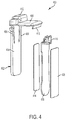
- FIG. 4 illustrates an exploded view of one example of a sensor assembly 400 .
- sensor assembly 400 provides sensor assembly 208 previously described and illustrated with reference to FIGS. 2A and 2B .
- Sensor assembly 400 includes a mounting bracket 402 , an adhesive material 414 , a printed circuit assembly (PCA) 416 , and a coverlay material 420 .
- PCA printed circuit assembly
- mounting bracket 402 is L-shaped and includes a first portion 404 for inserting into a housing and a second portion 408 attached to the first portion 404 at a right angle for covering a top portion of the housing.
- sensor assembly 400 is installable and removable from a housing.
- First portion 404 may include locking tabs 406 to hold mounting bracket 402 within a housing while enabling removal of mounting bracket 402 from the housing by pressing locking tabs 406 toward each other and lifting mounting bracket 402 out of the housing.
- Second portion 408 may include a tab 410 for aligning and attaching mounting bracket 402 to a housing.
- PCA 416 is attached to first portion 404 of mounting bracket 402 via adhesive material 414 .
- Adhesive material 414 may be a double sided pressure sensitive adhesive tape or another suitable adhesive material.
- PCA 416 includes a sensor (not shown) and a connector 418 .
- Connector 418 is electrically coupled to the sensor of PCA 416 and is accessible through an opening 412 of mounting bracket 408 to provide a signal line port.
- a coverlay material 420 such as a coverlay tape or another suitable coverlay material, is attached to PCA 416 opposite to adhesive material 414 .
- Coverlay material 420 electrically insulates the surface of PCA 416 .
- FIG. 5 is a circuit diagram illustrating one example of a sensor 500 .
- sensor 500 is part of PCA 416 previously described and illustrated with reference to FIG. 4 .
- Sensor 500 includes a capacitor 504 coupled in parallel with an inductive coil 506 across nodes 502 a and 502 b to provide a resonant circuit. The signal between nodes 502 a and 502 b provides the sensor signal.
- inductive coil 506 is integrated into a printed circuit board of the PCA. The inductance of inductive coil 506 changes based on the position of sensor 500 relative to a plate of the spring assembly of a collapsible container. Accordingly, sensor 500 may be used to sense the amount of ink or fluid within a collapsible container.
- FIG. 6 is a flow diagram illustrating one example of a method 600 for fabricating a printhead assembly, such as printhead assembly 200 previously described and illustrated with reference to FIGS. 2A and 2B .
- method 600 includes inserting a collapsible container into a housing.
- the collapsible container comprises flexible sidewalls and a spring assembly between the sidewalls.
- method 600 includes inserting a sensor assembly into the housing between a sidewall of the housing and a flexible sidewall of the collapsible container.
- the sensor assembly comprises a sensor to provide a sensor signal indicating the amount of ink within the collapsible container.
- the spring assembly comprises a first plate coupled to a second plate via a leaf spring and the first plate faces the sensor.
- the sensor senses the distance between the first plate and the sensor.
- the collapsible container is fabricated with a first flexible sidewall comprising more material than a second flexible sidewall opposite to the first flexible sidewall such that motion of the first flexible sidewall is less constrained than motion of the second flexible sidewall.
Landscapes
- Physics & Mathematics (AREA)
- General Physics & Mathematics (AREA)
- Engineering & Computer Science (AREA)
- Microelectronics & Electronic Packaging (AREA)
- Ink Jet (AREA)
Abstract
Description
Claims (20)
Priority Applications (1)
| Application Number | Priority Date | Filing Date | Title |
|---|---|---|---|
| US16/661,802 US10800176B2 (en) | 2015-12-11 | 2019-10-23 | Collapsible container and sensor |
Applications Claiming Priority (3)
| Application Number | Priority Date | Filing Date | Title |
|---|---|---|---|
| PCT/US2015/065357 WO2017099811A1 (en) | 2015-12-11 | 2015-12-11 | Collapsible container and sensor |
| US201815765256A | 2018-03-31 | 2018-03-31 | |
| US16/661,802 US10800176B2 (en) | 2015-12-11 | 2019-10-23 | Collapsible container and sensor |
Related Parent Applications (2)
| Application Number | Title | Priority Date | Filing Date |
|---|---|---|---|
| US15/765,256 Continuation US10471725B2 (en) | 2015-12-11 | 2015-12-11 | Collapsible container and sensor |
| PCT/US2015/065357 Continuation WO2017099811A1 (en) | 2015-12-11 | 2015-12-11 | Collapsible container and sensor |
Publications (2)
| Publication Number | Publication Date |
|---|---|
| US20200055317A1 US20200055317A1 (en) | 2020-02-20 |
| US10800176B2 true US10800176B2 (en) | 2020-10-13 |
Family
ID=59012873
Family Applications (2)
| Application Number | Title | Priority Date | Filing Date |
|---|---|---|---|
| US15/765,256 Expired - Fee Related US10471725B2 (en) | 2015-12-11 | 2015-12-11 | Collapsible container and sensor |
| US16/661,802 Expired - Fee Related US10800176B2 (en) | 2015-12-11 | 2019-10-23 | Collapsible container and sensor |
Family Applications Before (1)
| Application Number | Title | Priority Date | Filing Date |
|---|---|---|---|
| US15/765,256 Expired - Fee Related US10471725B2 (en) | 2015-12-11 | 2015-12-11 | Collapsible container and sensor |
Country Status (7)
| Country | Link |
|---|---|
| US (2) | US10471725B2 (en) |
| EP (1) | EP3386758A4 (en) |
| JP (1) | JP6840741B2 (en) |
| KR (2) | KR102228741B1 (en) |
| CN (1) | CN108136785B (en) |
| HK (1) | HK1258049A1 (en) |
| WO (1) | WO2017099811A1 (en) |
Families Citing this family (13)
| Publication number | Priority date | Publication date | Assignee | Title |
|---|---|---|---|---|
| WO2017099811A1 (en) * | 2015-12-11 | 2017-06-15 | Hewlett-Packard Development Company, L.P. | Collapsible container and sensor |
| US11427010B2 (en) | 2018-12-03 | 2022-08-30 | Hewlett-Packard Development Company, L.P. | Logic circuitry |
| US11338586B2 (en) | 2018-12-03 | 2022-05-24 | Hewlett-Packard Development Company, L.P. | Logic circuitry |
| WO2020117843A1 (en) | 2018-12-03 | 2020-06-11 | Hewlett-Packard Development Company, L.P. | Logic circuitry |
| US11366913B2 (en) | 2018-12-03 | 2022-06-21 | Hewlett-Packard Development Company, L.P. | Logic circuitry |
| PL3682359T3 (en) | 2018-12-03 | 2021-05-17 | Hewlett-Packard Development Company, L.P. | Logic circuitry |
| EP4235494A3 (en) | 2018-12-03 | 2023-09-20 | Hewlett-Packard Development Company, L.P. | Logic circuitry |
| MX2021005988A (en) | 2018-12-03 | 2021-07-06 | Hewlett Packard Development Co | Logic circuitry. |
| AU2018452257B2 (en) | 2018-12-03 | 2022-12-01 | Hewlett-Packard Development Company, L.P. | Logic circuitry |
| US20210372840A1 (en) | 2018-12-03 | 2021-12-02 | Hewlett-Packard Development Company, L.P. | Logic circuitry package |
| US11407229B2 (en) | 2019-10-25 | 2022-08-09 | Hewlett-Packard Development Company, L.P. | Logic circuitry package |
| EP4031997A1 (en) | 2020-04-30 | 2022-07-27 | Hewlett-Packard Development Company, L.P. | Logic circuitry package for print apparatus |
| EP4337469A4 (en) * | 2021-07-29 | 2024-07-31 | Hewlett-Packard Development Company, L.P. | STRESS DETECTION |
Citations (35)
| Publication number | Priority date | Publication date | Assignee | Title |
|---|---|---|---|---|
| DE3131944A1 (en) | 1980-08-13 | 1982-03-18 | Canon K.K., Tokyo | Device for measuring an ink residue volume |
| US5088077A (en) | 1988-11-10 | 1992-02-11 | Ampex Corporation | Synchronization of record media transports and tracking adjustment |
| JPH0815208A (en) | 1994-06-30 | 1996-01-19 | Mitsubishi Heavy Ind Ltd | Composite material damage detecting system |
| US5635962A (en) | 1995-07-24 | 1997-06-03 | Hewlett-Packard Company | Capacitive ink level detection sensor |
| GB2312283A (en) | 1996-04-17 | 1997-10-22 | Hewlett Packard Co | Inductive ink level detection mechanism |
| US5745137A (en) | 1992-08-12 | 1998-04-28 | Hewlett-Packard Company | Continuous refill of spring bag reservoir in an ink-jet swath printer/plotter |
| US5757406A (en) | 1992-08-12 | 1998-05-26 | Hewlett-Packard Company | Negative pressure ink delivery system |
| EP0882594A1 (en) | 1997-06-04 | 1998-12-09 | Hewlett-Packard Company | Ink container with an inductive ink level detection machanism attached to a collapsible ink bag |
| US5953030A (en) * | 1995-04-24 | 1999-09-14 | Canon Kabushiki Kaisha | Ink container with improved air venting structure |
| US6010212A (en) * | 1996-06-13 | 2000-01-04 | Minolta Co., Ltd. | Ink cartridge |
| KR100240540B1 (en) | 1996-03-14 | 2000-01-15 | 디. 크레이그 노룬드 | Syringe for filling print cartridge and establishing correct back pressure |
| US6270207B1 (en) * | 1998-03-30 | 2001-08-07 | Brother Kogyo Kabushiki Kaisha | Ink cartridge and remaining ink volume detection method |
| US6339335B1 (en) | 1997-10-10 | 2002-01-15 | Canon Kabushiki Kaisha | Method and device for determining the quantity of product contained in a reservoir, for example in an ink reservoir for a printer |
| JP2002127443A (en) | 2000-10-23 | 2002-05-08 | Canon Inc | Ink tank, ink remaining amount detection method, and recording apparatus |
| US6386693B1 (en) | 1999-05-06 | 2002-05-14 | Artech Gmbh Design And Production In Plastic | Ink supply tank for an inkjet print head |
| JP2002144598A (en) | 2000-11-13 | 2002-05-21 | Oki Data Corp | Liquid storage container |
| US6414894B2 (en) | 2000-05-24 | 2002-07-02 | Mitsubishi Denki Kabushiki Kaisha | Semiconductor device with reduced current consumption in standby state |
| JP2002267765A (en) | 2001-03-14 | 2002-09-18 | Matsushita Electric Works Ltd | Proximity sensor |
| JP2002337361A (en) | 2001-05-21 | 2002-11-27 | Sharp Corp | Ink container |
| US6520630B1 (en) * | 1999-12-28 | 2003-02-18 | Fuji Xerox Co., Ltd. | Ink jet recording apparatus |
| JP2003136749A (en) | 2001-11-05 | 2003-05-14 | Ricoh Co Ltd | ink cartridge |
| US20040027432A1 (en) | 1997-01-21 | 2004-02-12 | Childers Winthrop D. | Ink delivery system adapter |
| JP2004136670A (en) | 2002-09-25 | 2004-05-13 | Seiko Epson Corp | Liquid container |
| CN1532063A (en) | 2003-03-26 | 2004-09-29 | ������������ʽ���� | liquid container |
| US20070008365A1 (en) | 2005-07-05 | 2007-01-11 | Samsung Electronics Co., Ltd. | Ink cartridge including a unit to sense a remaining amount of ink |
| JP2007045016A (en) | 2005-08-10 | 2007-02-22 | Seiko Epson Corp | Liquid container, liquid remaining amount detection device, and recording device |
| US20080143345A1 (en) | 2006-12-18 | 2008-06-19 | Idir Boudaoud | Liquid level and composition sensing systems and methods using EMF wave propagation |
| US20090303299A1 (en) | 2008-05-22 | 2009-12-10 | Gilson Charles W | Ink containment system and ink level sensing system for an inkjet cartridge |
| JP2010208095A (en) | 2009-03-09 | 2010-09-24 | Ricoh Co Ltd | Recording agent storage container and image forming apparatus |
| US7922274B2 (en) | 2000-06-16 | 2011-04-12 | Canon Kabushiki Kaisha | Solid semiconductor element, ink tank, ink jet recording apparatus provided with ink tank, liquid information acquiring method and liquid physical property change discriminating method |
| CN102036828A (en) | 2008-05-22 | 2011-04-27 | 录象射流技术公司 | Ink containment system and ink level detection system for inkjet cartridges |
| CN102161273A (en) | 2010-11-23 | 2011-08-24 | 珠海天威技术开发有限公司 | Device and method for detecting and recording surplus of printer magnetic consumption body |
| US20110205315A1 (en) | 2010-02-25 | 2011-08-25 | Yukihiro Saga | Pressure damper, liquid jet head, and liquid jet apparatus |
| US8523339B2 (en) | 2010-12-06 | 2013-09-03 | Ricoh Company, Ltd. | Image forming apparatus |
| US10471725B2 (en) * | 2015-12-11 | 2019-11-12 | Hewlett-Packard Development Company, L.P. | Collapsible container and sensor |
Family Cites Families (1)
| Publication number | Priority date | Publication date | Assignee | Title |
|---|---|---|---|---|
| US6412894B1 (en) * | 2001-01-19 | 2002-07-02 | Lexmark International, Inc. | Ink cartridge and method for determining ink volume in said ink cartridge |
-
2015
- 2015-12-11 WO PCT/US2015/065357 patent/WO2017099811A1/en not_active Ceased
- 2015-12-11 EP EP15910424.9A patent/EP3386758A4/en not_active Withdrawn
- 2015-12-11 KR KR1020187008976A patent/KR102228741B1/en not_active Expired - Fee Related
- 2015-12-11 CN CN201580083521.0A patent/CN108136785B/en not_active Expired - Fee Related
- 2015-12-11 HK HK19100426.3A patent/HK1258049A1/en unknown
- 2015-12-11 US US15/765,256 patent/US10471725B2/en not_active Expired - Fee Related
- 2015-12-11 KR KR1020207013906A patent/KR20200056488A/en not_active Withdrawn
- 2015-12-11 JP JP2018515093A patent/JP6840741B2/en not_active Expired - Fee Related
-
2019
- 2019-10-23 US US16/661,802 patent/US10800176B2/en not_active Expired - Fee Related
Patent Citations (37)
| Publication number | Priority date | Publication date | Assignee | Title |
|---|---|---|---|---|
| DE3131944A1 (en) | 1980-08-13 | 1982-03-18 | Canon K.K., Tokyo | Device for measuring an ink residue volume |
| US5088077A (en) | 1988-11-10 | 1992-02-11 | Ampex Corporation | Synchronization of record media transports and tracking adjustment |
| US5745137A (en) | 1992-08-12 | 1998-04-28 | Hewlett-Packard Company | Continuous refill of spring bag reservoir in an ink-jet swath printer/plotter |
| US5757406A (en) | 1992-08-12 | 1998-05-26 | Hewlett-Packard Company | Negative pressure ink delivery system |
| JPH0815208A (en) | 1994-06-30 | 1996-01-19 | Mitsubishi Heavy Ind Ltd | Composite material damage detecting system |
| US5953030A (en) * | 1995-04-24 | 1999-09-14 | Canon Kabushiki Kaisha | Ink container with improved air venting structure |
| US5635962A (en) | 1995-07-24 | 1997-06-03 | Hewlett-Packard Company | Capacitive ink level detection sensor |
| KR100240540B1 (en) | 1996-03-14 | 2000-01-15 | 디. 크레이그 노룬드 | Syringe for filling print cartridge and establishing correct back pressure |
| GB2312283A (en) | 1996-04-17 | 1997-10-22 | Hewlett Packard Co | Inductive ink level detection mechanism |
| US6010212A (en) * | 1996-06-13 | 2000-01-04 | Minolta Co., Ltd. | Ink cartridge |
| US20040027432A1 (en) | 1997-01-21 | 2004-02-12 | Childers Winthrop D. | Ink delivery system adapter |
| CN1203358A (en) | 1997-06-04 | 1998-12-30 | 惠普公司 | Ink container with inductive ink level detection |
| EP0882594A1 (en) | 1997-06-04 | 1998-12-09 | Hewlett-Packard Company | Ink container with an inductive ink level detection machanism attached to a collapsible ink bag |
| US6339335B1 (en) | 1997-10-10 | 2002-01-15 | Canon Kabushiki Kaisha | Method and device for determining the quantity of product contained in a reservoir, for example in an ink reservoir for a printer |
| US6270207B1 (en) * | 1998-03-30 | 2001-08-07 | Brother Kogyo Kabushiki Kaisha | Ink cartridge and remaining ink volume detection method |
| US6386693B1 (en) | 1999-05-06 | 2002-05-14 | Artech Gmbh Design And Production In Plastic | Ink supply tank for an inkjet print head |
| US6520630B1 (en) * | 1999-12-28 | 2003-02-18 | Fuji Xerox Co., Ltd. | Ink jet recording apparatus |
| US6414894B2 (en) | 2000-05-24 | 2002-07-02 | Mitsubishi Denki Kabushiki Kaisha | Semiconductor device with reduced current consumption in standby state |
| US7922274B2 (en) | 2000-06-16 | 2011-04-12 | Canon Kabushiki Kaisha | Solid semiconductor element, ink tank, ink jet recording apparatus provided with ink tank, liquid information acquiring method and liquid physical property change discriminating method |
| JP2002127443A (en) | 2000-10-23 | 2002-05-08 | Canon Inc | Ink tank, ink remaining amount detection method, and recording apparatus |
| JP2002144598A (en) | 2000-11-13 | 2002-05-21 | Oki Data Corp | Liquid storage container |
| JP2002267765A (en) | 2001-03-14 | 2002-09-18 | Matsushita Electric Works Ltd | Proximity sensor |
| JP2002337361A (en) | 2001-05-21 | 2002-11-27 | Sharp Corp | Ink container |
| JP2003136749A (en) | 2001-11-05 | 2003-05-14 | Ricoh Co Ltd | ink cartridge |
| JP2004136670A (en) | 2002-09-25 | 2004-05-13 | Seiko Epson Corp | Liquid container |
| US20040252146A1 (en) | 2003-03-26 | 2004-12-16 | Takahiro Naka | Liquid container |
| CN1532063A (en) | 2003-03-26 | 2004-09-29 | ������������ʽ���� | liquid container |
| US20070008365A1 (en) | 2005-07-05 | 2007-01-11 | Samsung Electronics Co., Ltd. | Ink cartridge including a unit to sense a remaining amount of ink |
| JP2007045016A (en) | 2005-08-10 | 2007-02-22 | Seiko Epson Corp | Liquid container, liquid remaining amount detection device, and recording device |
| US20080143345A1 (en) | 2006-12-18 | 2008-06-19 | Idir Boudaoud | Liquid level and composition sensing systems and methods using EMF wave propagation |
| US20090303299A1 (en) | 2008-05-22 | 2009-12-10 | Gilson Charles W | Ink containment system and ink level sensing system for an inkjet cartridge |
| CN102036828A (en) | 2008-05-22 | 2011-04-27 | 录象射流技术公司 | Ink containment system and ink level detection system for inkjet cartridges |
| JP2010208095A (en) | 2009-03-09 | 2010-09-24 | Ricoh Co Ltd | Recording agent storage container and image forming apparatus |
| US20110205315A1 (en) | 2010-02-25 | 2011-08-25 | Yukihiro Saga | Pressure damper, liquid jet head, and liquid jet apparatus |
| CN102161273A (en) | 2010-11-23 | 2011-08-24 | 珠海天威技术开发有限公司 | Device and method for detecting and recording surplus of printer magnetic consumption body |
| US8523339B2 (en) | 2010-12-06 | 2013-09-03 | Ricoh Company, Ltd. | Image forming apparatus |
| US10471725B2 (en) * | 2015-12-11 | 2019-11-12 | Hewlett-Packard Development Company, L.P. | Collapsible container and sensor |
Non-Patent Citations (1)
| Title |
|---|
| Level Measurement Product Overview for Applications in Liquids and Bulk Solids, Internet Nov. 24, 2015; URL: <<https://www.google.co.in/url?sa=t&rct=j&q=&esrc=. |
Also Published As
| Publication number | Publication date |
|---|---|
| JP6840741B2 (en) | 2021-03-10 |
| US20180281428A1 (en) | 2018-10-04 |
| JP2018531812A (en) | 2018-11-01 |
| EP3386758A1 (en) | 2018-10-17 |
| KR20180048878A (en) | 2018-05-10 |
| EP3386758A4 (en) | 2019-08-07 |
| KR102228741B1 (en) | 2021-03-16 |
| US10471725B2 (en) | 2019-11-12 |
| WO2017099811A1 (en) | 2017-06-15 |
| HK1258049A1 (en) | 2019-11-01 |
| CN108136785B (en) | 2020-02-14 |
| US20200055317A1 (en) | 2020-02-20 |
| KR20200056488A (en) | 2020-05-22 |
| CN108136785A (en) | 2018-06-08 |
Similar Documents
| Publication | Publication Date | Title |
|---|---|---|
| US10800176B2 (en) | Collapsible container and sensor | |
| US6302527B1 (en) | Method and apparatus for transferring information between a printer portion and a replaceable printing component | |
| US6151039A (en) | Ink level estimation using drop count and ink level sense | |
| US6164743A (en) | Ink container with an inductive ink level sense | |
| US6988793B2 (en) | Collapsible ink reservoir with a collapse resisting insert | |
| US9333758B2 (en) | Liquid storage container and liquid ejection apparatus | |
| EP3225401B1 (en) | Liquid cartridge | |
| JP3667284B2 (en) | Liquid storage container and recording apparatus | |
| EP3260298A1 (en) | Liquid cartridge | |
| CA2413597C (en) | Non-contact communication between device and cartridge containing consumable component | |
| EP1199177B1 (en) | Ink bag and recording apparatus incorporating the same | |
| WO2019017963A1 (en) | Fluid level detector | |
| EP1647406B1 (en) | Transceiver controlling a plurality of antennas for communication with wireless memory devices in a printing system | |
| US10654280B2 (en) | Printhead assembly | |
| JP6730491B2 (en) | Foldable container and sensor | |
| US20220002109A1 (en) | Automatic document feeder with automated media tray | |
| US20120105519A1 (en) | Print cartridge identification system and method | |
| US20220041387A1 (en) | ADF With Automated Trays | |
| US20090274472A1 (en) | Replaceable printer component with electronic tag | |
| JP2003300646A (en) | Recording apparatus provided with recording medium thickness detection mechanism |
Legal Events
| Date | Code | Title | Description |
|---|---|---|---|
| AS | Assignment |
Owner name: HEWLETT-PACKARD DEVELOPMENT COMPANY, L.P., TEXAS Free format text: ASSIGNMENT OF ASSIGNORS INTEREST;ASSIGNORS:ESTERBERG, DENNIS R;JANSSEN, MATTHEW J;NIELSEN, JEFFREY A;AND OTHERS;REEL/FRAME:050808/0455 Effective date: 20151211 |
|
| FEPP | Fee payment procedure |
Free format text: ENTITY STATUS SET TO UNDISCOUNTED (ORIGINAL EVENT CODE: BIG.); ENTITY STATUS OF PATENT OWNER: LARGE ENTITY |
|
| STPP | Information on status: patent application and granting procedure in general |
Free format text: DOCKETED NEW CASE - READY FOR EXAMINATION |
|
| STPP | Information on status: patent application and granting procedure in general |
Free format text: RESPONSE TO NON-FINAL OFFICE ACTION ENTERED AND FORWARDED TO EXAMINER |
|
| STPP | Information on status: patent application and granting procedure in general |
Free format text: NOTICE OF ALLOWANCE MAILED -- APPLICATION RECEIVED IN OFFICE OF PUBLICATIONS |
|
| STPP | Information on status: patent application and granting procedure in general |
Free format text: PUBLICATIONS -- ISSUE FEE PAYMENT RECEIVED |
|
| STCF | Information on status: patent grant |
Free format text: PATENTED CASE |
|
| FEPP | Fee payment procedure |
Free format text: MAINTENANCE FEE REMINDER MAILED (ORIGINAL EVENT CODE: REM.); ENTITY STATUS OF PATENT OWNER: LARGE ENTITY |
|
| LAPS | Lapse for failure to pay maintenance fees |
Free format text: PATENT EXPIRED FOR FAILURE TO PAY MAINTENANCE FEES (ORIGINAL EVENT CODE: EXP.); ENTITY STATUS OF PATENT OWNER: LARGE ENTITY |
|
| STCH | Information on status: patent discontinuation |
Free format text: PATENT EXPIRED DUE TO NONPAYMENT OF MAINTENANCE FEES UNDER 37 CFR 1.362 |
|
| FP | Lapsed due to failure to pay maintenance fee |
Effective date: 20241013 |