US10799292B2 - High power tunable optical parametric oscillator for selective photothermolysis laser surgeries - Google Patents
High power tunable optical parametric oscillator for selective photothermolysis laser surgeries Download PDFInfo
- Publication number
- US10799292B2 US10799292B2 US15/970,910 US201815970910A US10799292B2 US 10799292 B2 US10799292 B2 US 10799292B2 US 201815970910 A US201815970910 A US 201815970910A US 10799292 B2 US10799292 B2 US 10799292B2
- Authority
- US
- United States
- Prior art keywords
- opo
- laser
- optical parametric
- parametric oscillator
- pulse
- Prior art date
- Legal status (The legal status is an assumption and is not a legal conclusion. Google has not performed a legal analysis and makes no representation as to the accuracy of the status listed.)
- Active, expires
Links
Images


Classifications
-
- A—HUMAN NECESSITIES
- A61—MEDICAL OR VETERINARY SCIENCE; HYGIENE
- A61B—DIAGNOSIS; SURGERY; IDENTIFICATION
- A61B18/00—Surgical instruments, devices or methods for transferring non-mechanical forms of energy to or from the body
- A61B18/18—Surgical instruments, devices or methods for transferring non-mechanical forms of energy to or from the body by applying electromagnetic radiation, e.g. microwaves
- A61B18/20—Surgical instruments, devices or methods for transferring non-mechanical forms of energy to or from the body by applying electromagnetic radiation, e.g. microwaves using laser
- A61B18/203—Surgical instruments, devices or methods for transferring non-mechanical forms of energy to or from the body by applying electromagnetic radiation, e.g. microwaves using laser applying laser energy to the outside of the body
-
- H—ELECTRICITY
- H01—ELECTRIC ELEMENTS
- H01S—DEVICES USING THE PROCESS OF LIGHT AMPLIFICATION BY STIMULATED EMISSION OF RADIATION [LASER] TO AMPLIFY OR GENERATE LIGHT; DEVICES USING STIMULATED EMISSION OF ELECTROMAGNETIC RADIATION IN WAVE RANGES OTHER THAN OPTICAL
- H01S3/00—Lasers, i.e. devices using stimulated emission of electromagnetic radiation in the infrared, visible or ultraviolet wave range
- H01S3/005—Optical devices external to the laser cavity, specially adapted for lasers, e.g. for homogenisation of the beam or for manipulating laser pulses, e.g. pulse shaping
-
- H—ELECTRICITY
- H01—ELECTRIC ELEMENTS
- H01S—DEVICES USING THE PROCESS OF LIGHT AMPLIFICATION BY STIMULATED EMISSION OF RADIATION [LASER] TO AMPLIFY OR GENERATE LIGHT; DEVICES USING STIMULATED EMISSION OF ELECTROMAGNETIC RADIATION IN WAVE RANGES OTHER THAN OPTICAL
- H01S3/00—Lasers, i.e. devices using stimulated emission of electromagnetic radiation in the infrared, visible or ultraviolet wave range
- H01S3/09—Processes or apparatus for excitation, e.g. pumping
- H01S3/091—Processes or apparatus for excitation, e.g. pumping using optical pumping
- H01S3/094—Processes or apparatus for excitation, e.g. pumping using optical pumping by coherent light
-
- H—ELECTRICITY
- H01—ELECTRIC ELEMENTS
- H01S—DEVICES USING THE PROCESS OF LIGHT AMPLIFICATION BY STIMULATED EMISSION OF RADIATION [LASER] TO AMPLIFY OR GENERATE LIGHT; DEVICES USING STIMULATED EMISSION OF ELECTROMAGNETIC RADIATION IN WAVE RANGES OTHER THAN OPTICAL
- H01S3/00—Lasers, i.e. devices using stimulated emission of electromagnetic radiation in the infrared, visible or ultraviolet wave range
- H01S3/10—Controlling the intensity, frequency, phase, polarisation or direction of the emitted radiation, e.g. switching, gating, modulating or demodulating
- H01S3/10053—Phase control
-
- H—ELECTRICITY
- H01—ELECTRIC ELEMENTS
- H01S—DEVICES USING THE PROCESS OF LIGHT AMPLIFICATION BY STIMULATED EMISSION OF RADIATION [LASER] TO AMPLIFY OR GENERATE LIGHT; DEVICES USING STIMULATED EMISSION OF ELECTROMAGNETIC RADIATION IN WAVE RANGES OTHER THAN OPTICAL
- H01S3/00—Lasers, i.e. devices using stimulated emission of electromagnetic radiation in the infrared, visible or ultraviolet wave range
- H01S3/14—Lasers, i.e. devices using stimulated emission of electromagnetic radiation in the infrared, visible or ultraviolet wave range characterised by the material used as the active medium
- H01S3/16—Solid materials
- H01S3/1601—Solid materials characterised by an active (lasing) ion
- H01S3/1603—Solid materials characterised by an active (lasing) ion rare earth
- H01S3/1611—Solid materials characterised by an active (lasing) ion rare earth neodymium
-
- H—ELECTRICITY
- H01—ELECTRIC ELEMENTS
- H01S—DEVICES USING THE PROCESS OF LIGHT AMPLIFICATION BY STIMULATED EMISSION OF RADIATION [LASER] TO AMPLIFY OR GENERATE LIGHT; DEVICES USING STIMULATED EMISSION OF ELECTROMAGNETIC RADIATION IN WAVE RANGES OTHER THAN OPTICAL
- H01S3/00—Lasers, i.e. devices using stimulated emission of electromagnetic radiation in the infrared, visible or ultraviolet wave range
- H01S3/14—Lasers, i.e. devices using stimulated emission of electromagnetic radiation in the infrared, visible or ultraviolet wave range characterised by the material used as the active medium
- H01S3/16—Solid materials
- H01S3/163—Solid materials characterised by a crystal matrix
- H01S3/164—Solid materials characterised by a crystal matrix garnet
- H01S3/1643—YAG
-
- A—HUMAN NECESSITIES
- A61—MEDICAL OR VETERINARY SCIENCE; HYGIENE
- A61B—DIAGNOSIS; SURGERY; IDENTIFICATION
- A61B17/00—Surgical instruments, devices or methods, e.g. tourniquets
- A61B2017/00017—Electrical control of surgical instruments
- A61B2017/00137—Details of operation mode
- A61B2017/00154—Details of operation mode pulsed
- A61B2017/00172—Pulse trains, bursts, intermittent continuous operation
-
- A—HUMAN NECESSITIES
- A61—MEDICAL OR VETERINARY SCIENCE; HYGIENE
- A61B—DIAGNOSIS; SURGERY; IDENTIFICATION
- A61B17/00—Surgical instruments, devices or methods, e.g. tourniquets
- A61B2017/00017—Electrical control of surgical instruments
- A61B2017/00137—Details of operation mode
- A61B2017/00154—Details of operation mode pulsed
- A61B2017/00181—Means for setting or varying the pulse energy
- A61B2017/0019—Means for setting or varying the pulse width
-
- A—HUMAN NECESSITIES
- A61—MEDICAL OR VETERINARY SCIENCE; HYGIENE
- A61B—DIAGNOSIS; SURGERY; IDENTIFICATION
- A61B17/00—Surgical instruments, devices or methods, e.g. tourniquets
- A61B2017/00743—Type of operation; Specification of treatment sites
- A61B2017/00747—Dermatology
- A61B2017/00769—Tattoo removal
-
- A—HUMAN NECESSITIES
- A61—MEDICAL OR VETERINARY SCIENCE; HYGIENE
- A61B—DIAGNOSIS; SURGERY; IDENTIFICATION
- A61B18/00—Surgical instruments, devices or methods for transferring non-mechanical forms of energy to or from the body
- A61B2018/00315—Surgical instruments, devices or methods for transferring non-mechanical forms of energy to or from the body for treatment of particular body parts
- A61B2018/00452—Skin
-
- A—HUMAN NECESSITIES
- A61—MEDICAL OR VETERINARY SCIENCE; HYGIENE
- A61B—DIAGNOSIS; SURGERY; IDENTIFICATION
- A61B18/00—Surgical instruments, devices or methods for transferring non-mechanical forms of energy to or from the body
- A61B2018/00636—Sensing and controlling the application of energy
- A61B2018/00696—Controlled or regulated parameters
- A61B2018/00702—Power or energy
-
- A—HUMAN NECESSITIES
- A61—MEDICAL OR VETERINARY SCIENCE; HYGIENE
- A61B—DIAGNOSIS; SURGERY; IDENTIFICATION
- A61B18/00—Surgical instruments, devices or methods for transferring non-mechanical forms of energy to or from the body
- A61B2018/00636—Sensing and controlling the application of energy
- A61B2018/00696—Controlled or regulated parameters
- A61B2018/00761—Duration
-
- A—HUMAN NECESSITIES
- A61—MEDICAL OR VETERINARY SCIENCE; HYGIENE
- A61B—DIAGNOSIS; SURGERY; IDENTIFICATION
- A61B18/00—Surgical instruments, devices or methods for transferring non-mechanical forms of energy to or from the body
- A61B18/18—Surgical instruments, devices or methods for transferring non-mechanical forms of energy to or from the body by applying electromagnetic radiation, e.g. microwaves
- A61B18/20—Surgical instruments, devices or methods for transferring non-mechanical forms of energy to or from the body by applying electromagnetic radiation, e.g. microwaves using laser
- A61B18/22—Surgical instruments, devices or methods for transferring non-mechanical forms of energy to or from the body by applying electromagnetic radiation, e.g. microwaves using laser the beam being directed along or through a flexible conduit, e.g. an optical fibre; Couplings or hand-pieces therefor
- A61B2018/2255—Optical elements at the distal end of probe tips
- A61B2018/2261—Optical elements at the distal end of probe tips with scattering, diffusion or dispersion of light
-
- H—ELECTRICITY
- H01—ELECTRIC ELEMENTS
- H01S—DEVICES USING THE PROCESS OF LIGHT AMPLIFICATION BY STIMULATED EMISSION OF RADIATION [LASER] TO AMPLIFY OR GENERATE LIGHT; DEVICES USING STIMULATED EMISSION OF ELECTROMAGNETIC RADIATION IN WAVE RANGES OTHER THAN OPTICAL
- H01S3/00—Lasers, i.e. devices using stimulated emission of electromagnetic radiation in the infrared, visible or ultraviolet wave range
- H01S3/005—Optical devices external to the laser cavity, specially adapted for lasers, e.g. for homogenisation of the beam or for manipulating laser pulses, e.g. pulse shaping
- H01S3/0092—Nonlinear frequency conversion, e.g. second harmonic generation [SHG] or sum- or difference-frequency generation outside the laser cavity
-
- H—ELECTRICITY
- H01—ELECTRIC ELEMENTS
- H01S—DEVICES USING THE PROCESS OF LIGHT AMPLIFICATION BY STIMULATED EMISSION OF RADIATION [LASER] TO AMPLIFY OR GENERATE LIGHT; DEVICES USING STIMULATED EMISSION OF ELECTROMAGNETIC RADIATION IN WAVE RANGES OTHER THAN OPTICAL
- H01S3/00—Lasers, i.e. devices using stimulated emission of electromagnetic radiation in the infrared, visible or ultraviolet wave range
- H01S3/23—Arrangements of two or more lasers not provided for in groups H01S3/02 - H01S3/22, e.g. tandem arrangements of separate active media
- H01S3/2308—Amplifier arrangements, e.g. MOPA
-
- H—ELECTRICITY
- H01—ELECTRIC ELEMENTS
- H01S—DEVICES USING THE PROCESS OF LIGHT AMPLIFICATION BY STIMULATED EMISSION OF RADIATION [LASER] TO AMPLIFY OR GENERATE LIGHT; DEVICES USING STIMULATED EMISSION OF ELECTROMAGNETIC RADIATION IN WAVE RANGES OTHER THAN OPTICAL
- H01S3/00—Lasers, i.e. devices using stimulated emission of electromagnetic radiation in the infrared, visible or ultraviolet wave range
- H01S3/23—Arrangements of two or more lasers not provided for in groups H01S3/02 - H01S3/22, e.g. tandem arrangements of separate active media
- H01S3/2383—Parallel arrangements
Definitions
- This document relates to techniques and methods for selective photothermolysis (SP) laser surgeries.
- SP as described by Anderson and Parrish in a paper published by SCIENCE in 1983, utilizes short laser pulses to precisely control collateral thermal or mechanical damages around light-absorptive lesions without the need of aiming a laser micro-beam at surgical targets.
- a SP laser surgery has two distinct features, a large surgical area and a short surgical laser pulse that deposits most of the laser pulse energy into surgical targets. Thus non-surgical targets within a large surgical area remain healthy after SP while all surgical targets are damaged.
- Typical SP laser surgery examples include laser treatment of vascular malformations, some laser retinal photocoagulation surgeries, and some aesthetical laser surgeries such as laser tattoo removal.
- there is a big gap between the SP theory and SP laser surgery practices due to technical limitations.
- This document relates to techniques, apparatus and methods for optimized selective photothermolysis (SP) laser surgeries.
- a high power tunable optical parametric oscillator system for SP laser surgeries comprises a pump laser that generates multiple high power, pulsed, pump laser beams; an optical parametric oscillator with multiple parallel optical parametric oscillator (OPO) modules pumped by the multiple pump laser beams, and multiple output beams whose lasing wavelengths are determined by phase-matching conditions of the OPO crystals within the OPO modules; a light delivery unit that assembles OPO output beams, adjusts diameters of OPO output beams, and directs OPO output beams to patient interface with an articulated arm or an optical light-guide including optical fibers; and a patient interface comprising a scattering medium that effectively combines multiple OPO output beams with high transmission through the scattering medium and disperses the combined laser energy on tissue surface.
- OPO optical parametric oscillator
- Such a high power tunable optical parametric oscillator system can be utilized to perform SP laser surgeries with known laser parameters.
- a high power tunable optical parametric oscillator system for SP laser surgeries comprises a pump laser that generates multiple high power, pulsed, pump laser beams; an optical parametric oscillator with multiple parallel optical parametric oscillator (OPO) modules pumped by the multiple pump laser beams, and multiple output beams whose lasing wavelengths are determined by phase-matching conditions of the OPO crystals within the OPO modules; a light delivery unit that assembles OPO output beams, adjusts diameters of OPO output beams, and directs OPO output beams to patient interface with an articulated arm or an optical light-guide including optical fibers; and a patient interface comprising an acoustic detector for acquiring photoacoustic responses of tissue upon excitation by pulsed OPO output beams, and a scattering medium that effectively combines the multiple OPO output beams with high transmission through the scattering medium and disperses the combined laser energy on tissue surface.
- OPO optical parametric oscillator
- FIG. 1 shows an example of a high power tunable optical parametric oscillator with multiple output beams that are combined and dispersed on tissue surface by a scattering medium within a patient interface.
- FIG. 2 show an example of pump laser that generates multiple 355 nm pump laser beams.
- FIG. 3 shows an example of optical parametric oscillator that comprises multiple optical parametric oscillator modules and multiple output beams.
- FIG. 4 shows an example of optical parametric oscillator module shown in FIG. 3 .
- FIG. 5 shows an example of a patient interface that comprises a scattering medium for combining and dispersing multiple output beams on tissue surface for SP laser surgeries with known laser parameters.
- FIG. 6 shows another example of a patient interface that allows acquiring tissue responses and optimal laser parameters with an acoustic detector, combining multiple output beams and dispersing combined energies on tissue surface by a scattering medium.
- SP Selective photothermolysis
- SP utilizes short laser pulses to precisely target light-absorptive lesions with minimum collateral thermal or mechanical damages to surrounding healthy tissue.
- Major SP commercial applications include laser tattoo removal, laser treatment of vascular malformations and laser retinal photocoagulation.
- Laser tattoo removal is usually performed with very short laser pulses in nanosecond or picosecond regime.
- Laser energy is transformed into both thermal energy and mechanical energy carried by the photoacoustic waves.
- large laser pulse energy absorbed by pigmented particles may cause optical breakdown, plasma generation, chemical reactions between plasma and pigmented particles, cavitation and generation of acoustic shock-waves.
- These pigmented particles might be pyrolytically altered or shattered into smaller particles by the photoacoustic waves and acoustic shock-waves.
- Hosting cell necrosis and surround tissue damage might be induced thermally and mechanically during this process.
- the wound healing process might remove partial pigmented particles through rephagocytosis and alter the dermal scattering coefficients of the affected tissue, which might make the deeper pigmented particles less visible.
- a large number of tattoo inks of different colors with different light absorbing characteristics could be applied within human skin by tattoo artists.
- laser wavelengths for example, 694 nm ruby laser, 755 nm Alexandrite, 1064 nm Nd:YAG and 532 nm second harmonic generation of Nd:YAG
- the tattoo-removal laser wavelength is selected based on the tattoo's color appearance to the naked eye instead of an optimal wavelength that damages pigmented lesions and protects nature chromophores in tissue to a maximum extent.
- the techniques, apparatus and methods disclosed in U.S. Ser. No. 15/881,748 addressed the problem of how to acquire optimal SP laser treatment parameters including wavelength selection.
- the problem to be addressed here is how to implement a high power tunable SP laser for demanding SP applications such as laser tattoo removal since such a laser does not exist so far.
- the solution to the problem could also apply to the laser treatment of vascular malformations wherein a number of discrete wavelengths (for example, 488/514 nm by Argon laser, 520/530 nm by Krypton laser, 532 nm by second harmonic generation of Nd:YAG laser, 578 nm by copper bromide/copper vapor laser, 585/595 nm by pulsed dye laser, 755 nm by Alexandrite laser, 800-940 nm by laser diode, and 1064 nm by Nd:YAG laser) are currently available for the photocoagulation of vascular lesions.
- a number of discrete wavelengths for example, 488/514 nm by Argon laser, 520/530 nm by Krypton laser, 532 nm by second harmonic generation of Nd:YAG laser, 578 nm by copper bromide/copper vapor laser, 585/595 nm by pulsed dye laser, 755 nm by Alexandrite laser, 800-940
- Laser wavelength is determined by both the gain medium and wavelength selection mechanism in the laser cavity.
- the wavelength tuning range is determined by the spontaneous emission spectrum and the threshold condition of the laser cavity.
- Most solid state laser gain medium for example, Ti:Sapphire 670-1070 nm, Cr:LiSAF 780-920 nm, Alexandrite 700-800 nm, and Cr:GSGG 700-900 nm) barely covers visible light range.
- Laser dyes for example, Fluorescein-27 in Ethanol & water 541-571 nm, Pyrromethene-580 in Ethanol 547-581 nm, Rhodamine-6G 556-582 nm, Pyrromethene-597 558-587 nm, Sulforhodamine-B in Ethanol 585-600 nm, Rhodamine-B in Ethanol 588-614 nm, Rhodamine-101 in Ethanol 614-662 nm, DCM in Ethanol 595-665 nm, DCM in DMSO 616-690 nm, Pyridine-1 in Ethanol 667-720 nm, Pyridine-2 in Ethanol 691-751 nm, Styryl-8 in Ethanol 712-182 nm, Styryl-8 in DMSO 733-802 nm, Styryl-11 in Ethanol 758-826 nm, Sty
- Optical parametric oscillator based on parametric down conversion process by non-linear OPO crystals has potential to generate widely-tuning laser wavelengths within VIS-NIR for SP.
- a non-linear OPO crystal emits a signal photon of wavelength ⁇ s and an idle photon of wavelength ⁇ i when it is pumped by an excitation laser photon of wavelength ⁇ p. Both energy and momentum are preserved in the optical parametric down conversion process.
- the phase matching condition determines ⁇ s and ⁇ i. Adjusting phase matching conditions can effectively tune the output laser wavelength of OPO.
- the first commercial OPO device was introduced in early 1970s.
- OPOs are easily damaged and that make OPOs less useful than tunable dye laser for almost 20 years before the discovery of damage-resistant nonlinear crystals with large nonlinear coefficients in the early 1990s.
- VIS-NIR OPOs are currently widely used in many applications due to its continuous, wide wavelength tuning capability.
- OPO seems simple and elegant, it is difficult to make high-power OPOs due to the potential damages to the OPO crystals, limited aperture size of OPO crystals, and high requirements on pump laser beam for high parametric conversion efficiency, especially the low pump beam divergence of 0.5-1 milliradian.
- a low cost commercial OPO laser (basiScan-HE280 by Spectra Physics) only allows a maximum 280 mJ pump laser (355 nm) energy and generates a maximum signal output of 95 mJ.
- Another more advanced OPO (PrimoScan-BB750 OPO by Spectra Physics) delivers a maximum signal output of about 200 mJ with a 750 mJ pump laser (355 nm) energy and a large OPO crystal that accommodates 14 mm diameter beams.
- several hundred mJ of laser pulse energy is required by demanding SP applications such as laser tattoo removal.
- the most powerful commercial OPOs might not satisfy demanding SP applications.
- the prior art is deficient in high power, widely-tunable lasers for demanding SP applications such as laser tattoo removal.
- Both a VIS-NIR tunable dye laser and a VIS-NIR tunable OPO have similar low pump efficiencies and require high-power solid-state pump laser.
- a VIS-NIR OPO should be a better solution for demanding SP applications than a VIS-NIR tunable dye laser when the OPO's power could satisfy SP applications.
- This invention discloses techniques and methods on how to implement a high power VIS-NIR OPO for demanding SP applications such as laser tattoo removal. Detailed descriptions of this invention are provided below.
- FIG. 1 shows an example of a high power, tunable optical parametric oscillator system wherein the generations of multiple output beams upon pumping by multiple pump beams, and the inclusion of a scattering medium in its patient interface differentiate it from a conventional tunable optical parametric oscillator in prior art of this invention.
- This high power, tunable optical parametric oscillator system comprises a high-power, solid state pump laser 1100 with multiple pump laser beams 1020 ; an optical parametric oscillator 1200 with multiple OPO laser beams 1040 as its output; a laser delivery unit 1300 that assembles multiple OPO laser beams 1040 , adjusts diameters of the OPO laser beams 1040 , delivers the OPO laser beams 1040 with an articulated arm or with an optical light-guide including optical fibers, and transmits the OPO laser beams 1040 through a patient interface 1400 comprising a scattering medium 1420 to a tissue 1000 surface; and a patient interface 1400 operable to be in contact with a tissue 1000 surface.
- the high power, tunable optical parametric oscillator system generates pulsed OPO laser beams that fulfill requirements of SP applications.
- the pulse duration of OPO laser beams is less than 10 ⁇ 7 seconds, or less than 10 ⁇ 8 seconds, or less than 10 ⁇ 9 seconds.
- the pulse duration or the pulse-train duration of OPO laser beams is longer than 1 millisecond.
- this invention adopts a strategy that divides the high-power pump energy into multiple pump laser beams 1020 that pump multiple OPO crystals. This is the first characteristics of this invention.
- the spatially separated OPO output beams are combined and dispersed onto tissue surface by a patient interface comprising a scattering medium.
- This invention provides hardware part of a tunable laser that serves as the tunable light source disclosed in U.S. Ser. No. 15/881,748.
- the pulse energy of OPO laser beams 1040 can be tuned by adjusting the pulse energy of pump laser 1100 .
- the pulse duration or pulse-train duration of OPO laser beams 1040 can be tuned by adjusting the pulse duration or pulse-train duration of the pump laser 1100 accordingly.
- the wavelength tuning of OPO laser beams 1040 is achieved by adjusting phase matching conditions of OPO crystals (not shown by FIG. 1 ) inside the optical parametric oscillator 1200 .
- detailed examples of the pump laser 1100 , the optical parametric oscillator 1200 , and the patient interface 1400 are disclosed.
- Solid state laser has become a mature technique that can be utilized to build the master oscillator of a high power pump laser with a “MOPA” (Master Oscillator Power Amplifier) structure.
- the master oscillator of the high power pump laser has only low to medium power, but high time and spatial coherence required by applications. It is the power amplifier after the master oscillator that achieves high power required by applications. Both the master oscillator and power amplifier can be pumped by flash-lamps, arc-lamps or laser diodes.
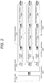
- FIG. 2 shows an example of a high power pump laser of 355 nm with multiple pump laser beams for pumping VIS-NIR OPO.
- the pump laser of this particular example has a pulse duration in nanosecond or picosecond regime for the laser tattoo removal application.
- a Nd:YAG lase 2100 serves as the main oscillator of the pump laser and generates a fundamental 1064 nm laser beam 2020 with a low-to-medium pulse energy, a narrow bandwidth, a low M2 factor and a low beam divergence.
- the 1064 nm laser beam 2020 is divided into multiple (from #1 to # N) 1064 nm laser beams 2020 for pumping multiple (from #1 to # N) third harmonic modules 2300 that generate multiple (#1 to # N) 355 nm pump laser beams 2060 for optical parametric down conversion.
- each third harmonic module 2300 the power of each input 1064 nm laser beam 2020 is amplified by an amplifier 2320 before sequentially pumping a second harmonic generation (SHG) 2340 unit and a sum frequency generation (SFG) 2360 unit for the generation of the 355 nm pump laser beam 2060 .
- 1064 & 532 nm laser beams 2040 serve as inputs to the sum frequency generation (SFG) 2360 units.
- the SFG 2360 unit could be skipped when multiple pump laser beams are required at 532 nm instead of 355 nm, and the SHG 2340 unit could be further optimized to ⁇ 70% efficiency.
- FIG. 3 shows an example of optical parametric oscillator that comprises multiple (from #1 to # N) optical parametric oscillator modules 3200 that convert 355 nm pump laser beam 3100 energy into output laser beam 3300 energy at a wavelength determined by phase matching conditions of the non-linear OPO crystals (for example, phase matching angle or temperature of the non-linear OPO crystals) inside the optical parametric oscillator module 3200 .
- the optical parametric oscillator of this example has a pulse duration that is slightly shorter than the 355 nm pump laser beam 3100 because of a short period of time is required to build up optical parametric oscillation within the optical parametric oscillator cavity.
- Each optical parametric oscillator module could have its own oscillator cavity mirrors or share a pair of large cavity mirrors when a more compact design of the optical parametric oscillator is adopted.
- the multiple (from #1 to # N) output beams 3300 could be selectable between the OPO signal beams and OPO idler beams if it is desirable for the SP applications.
- FIG. 4 details an example of the optical parametric oscillator module 3200 of FIG. 3 .
- Three pump mirrors 4100 inject pump laser beam 4020 into the optical parametric oscillator cavity comprising a cavity end mirror 4200 , two BBO crystals 4300 and a cavity output mirror 4400 .
- the cavity output mirror 4400 outputs partial signal and idler wave and reflects the rest back to oscillator cavity for oscillation.
- the cavity end mirror 4200 is highly reflective for both signal wave and idler wave in a dual-resonant oscillator (DRO) design.
- DRO dual-resonant oscillator
- a pair of dichroic mirrors 4500 are used to separate the signal wave 4040 and idler wave 4060 .
- the output beam 4080 can be selected from the signal wave 4040 and idler wave 4060 by a moveable reflector 4600 that deflects the unselected beam, which is the idler beam in this example, to a beam dumper 4700 .
- both OPO crystals are cut with type-I phase matching with 355 nm pump laser. But the appropriate orientation of the two BBO crystals relative to each other allows the compensation of birefringence walk-off and improvement of conversion efficiency.
- the tuning of wavelengths of the signal and the idler waves is achieved by rotation of the first BBO crystal and the second BBO crystal around the axes (identified by the black dots below the crystals) below the crystal along anti-clock-wise and clock-wise directions respectively.
- Modifications such as double-pass of pump laser beams through the OPO crystals or a better ring cavity design may reduce pump threshold, extract more laser energy out of oscillator, and allow higher conversion efficiency. It is understandable that the purpose of this example is to demonstrate that this invention is practical, not to include all possible OPO technique features. Dividing high power pump energy and utilizing multiple parallel optical parametric oscillator modules are keys to overcome technique limitations in prior arts of high power optical parametric oscillator.
- a laser delivery unit 1300 assembles OPO laser beams 1040 , adjusts diameters of the OPO laser beams 1040 , delivers the OPO laser beams 1040 with an articulated arm or with an optical light-guide including optical fibers, passes the OPO laser beams 1040 through a patient interface, and illuminates a tissue surface region with laser influences that match with SP applications.
- a simple patient interface as shown in FIG. 5 can combine energies of OPO laser beams 1040 , and disperse the combined laser energies onto a tissue surface.
- the scattering medium 5200 has a minimum optical absorption to light in VIS-NIR wavelength range and a high transmission to OPO output beams 5100 .
- the scattering medium 5200 can be conventional optical diffusers, such as ground glass, engineered diffusers or holographic diffusers with high transmission.
- the scattering medium 5200 can also be any form of high-transmission light guide filled with liquid, solid or gel scattering phantoms containing light scattering particles, with size comparable to wavelengths of visible light.
- the scattering medium 5200 can pass 80-90% of light energy when it disperses the laser beams.
- Monte Carol simulation of light transport through the scattering phantom or experimental methods can optimize scattering phantom parameters including the phantom thickness, particle concentration, particle size, light loss, and illuminated area.
- Conventional optical simulation or experimental methods can be used for the optimized design of conventional optical diffusers.
- the utilization of a scattering medium to combine laser energies of multiple output beams for demanding SP applications is another key of this invention.
- FIG. 6 shows a general patient interface that allows the acquisition of optimal treatment laser parameters and laser treatment with optimal laser parameters.
- This general patient interface comprises an acoustic wave reflector 6200 , an interface media 6300 , a linear arrayed ultrasonic transducer 6400 , and a scattering medium 6500 between the interface medium 6300 and tissue 6600 .
- the interface medium 6300 and the acoustic reflector 6200 are transparent to the OPO output beams 6100 while the scattering medium 6500 combine and disperse the OPO output beams 6100 onto a circular area on tissue 6000 surface after the OPO output beams 6100 pass through the scattering medium 6500 with high transmission.
- the pigmented lesions embedded in tissue are treated by the OPO output beams 6100 upon absorption of laser pulse energy.
- the pigmented lesions can also generate photoacoustic waves upon the excitation of the OPO output beams 6100 .
- the photoacoustic waves travel upward through the scattering medium 6500 and interface medium 6300 before being reflected by the acoustic reflector 6200 and detected by the linear arrayed ultrasonic transducer 6400 .
- the acoustic impedances of interface medium 6300 , scattering medium 6500 and tissue 6600 are preferable to be close in order to minimize loss of photoacoustic waves before the photoacoustic waves are detected by the linear arrayed ultrasonic transducer 6400 .
- acoustic reflector 6200 and the linear arrayed ultrasonic transducer 6400 are static, only two-dimensional tissue information beneath the illuminated tissue 6000 surface area can be acquired for the acquisition of optimal laser parameters.
- a rotational stage (not shown in FIG. 6 ) that mounts the acoustic reflector 6200 and the linear arrayed ultrasonic transducer 6400 and rotates them around the scan rotational axis 6700 along scan rotational direction 6800 , a three-dimensional tissue information beneath the illuminated tissue 6000 surface area can be acquired for the acquisition of optimal laser parameters.
- Optimal laser treatment parameters can be applied for the optimized laser treatment thereafter.
Abstract
Description
- U.S. Pat. No. 6,607,523 B1 Filed December 2001 by Asah et al.
- U.S. Pat. No. 6,723,090 B2 Filed July 2002 by Altshuler et al.
- U.S. Pat. No. 6,766,187 B1 Filed September 2000 by Black et al.
- U.S. Pat. No. 5,390,211 Filed in August 2093 by Clark et al.
- U.S. Pat. No. 7,036,516 B1 Filed August 2098 by Dees et al.
- U.S. Pat. No. 5,619,517 Filed in February 2095 by Dixon et al.
- U.S. Pat. No. 6,270,492 B1 Filed September 2099 by Edward L. Sinofsky.
- U.S. Pat. No. 6,273,883 B1 Filed April 2097 by Furumoto et al.
- U.S. Pat. No. 5,117,126 Filed in June 2090 by Geiger et al.
- U.S. Pat. No. 7,179,253 B2 Filed March 2004 by Graham et al.
- U.S. Pat. No. 7,331,953 B2 Filed April 2005 by Manstein et al.
- U.S. Pat. No. 8,394,359 B1 Filed March 2012 by Michael P. O'Neil.
- U.S. Pat. No. 6,554,825 B1 Filed May 2000 by Murray et al.
- 00RE36634 Filed December 2091 by Shahriar Ghaffari et al.
- 2013/0345685 A1 Filed May 2013 by Poran et al.
- Ser. No. 15/881,748 Filed in January 2018 by Rao Bin.
- U.S. Pat. No. 7,713,265 B2 Filed December 2006 by Robert J. Dunki-Jacobs.
- U.S. Pat. No. 5,879,346 Filed December 2096 by Waldman et al.
- U.S. Pat. No. 5,759,200 Filed September 2096 by Zion Azar.
- WO 2013/033145A1 Filed in August 2011 by Nikolai et al.
- Barua et al., “Laser-tissue interaction in tattoo removal by Q-switched lasers,” J Cutan Aesthet Surg 8, 5-8(2015).
- Bernstein, “Laser Tattoo Removal,” SEMINARS IN PLASTICS SURGERY 21, 175-192(2007).
- Ortiz et al., “Port-wine stain laser treatment and novel approaches,” Facial Plast Surg 28, 611-620(2012).
- Peach et al., “Colour shift following tattoo removal with Q-switched Nd-YAG laser (1064/532),” British Journal of Plastic Surgery 52,482-487(1999).
- Walter Koechner. Solid-state Laser Engineering. Springer 2006. Print.
- Wenzel, “Current concepts in laser tattoo removal,” Skin Therapy Letter 15, 3-5(2010).
- http://www.spectra-physics.com/products/hidh-enerdy-pulsed-lasers/primoscan-opo [Accessed 2 May 2018]
- http://www.spectra-physics.com/products/hidh-enerdy-pulsed-lasers/basiscan [Accessed 2 May 2018]
Claims (13)
Priority Applications (1)
| Application Number | Priority Date | Filing Date | Title |
|---|---|---|---|
| US15/970,910 US10799292B2 (en) | 2018-05-04 | 2018-05-04 | High power tunable optical parametric oscillator for selective photothermolysis laser surgeries |
Applications Claiming Priority (1)
| Application Number | Priority Date | Filing Date | Title |
|---|---|---|---|
| US15/970,910 US10799292B2 (en) | 2018-05-04 | 2018-05-04 | High power tunable optical parametric oscillator for selective photothermolysis laser surgeries |
Publications (2)
| Publication Number | Publication Date |
|---|---|
| US20190336213A1 US20190336213A1 (en) | 2019-11-07 |
| US10799292B2 true US10799292B2 (en) | 2020-10-13 |
Family
ID=68384362
Family Applications (1)
| Application Number | Title | Priority Date | Filing Date |
|---|---|---|---|
| US15/970,910 Active 2038-10-05 US10799292B2 (en) | 2018-05-04 | 2018-05-04 | High power tunable optical parametric oscillator for selective photothermolysis laser surgeries |
Country Status (1)
| Country | Link |
|---|---|
| US (1) | US10799292B2 (en) |
Families Citing this family (3)
| Publication number | Priority date | Publication date | Assignee | Title |
|---|---|---|---|---|
| JP2022553632A (en) | 2019-11-08 | 2022-12-26 | カリフォルニア インスティチュート オブ テクノロジー | wavelength scale optical parametric oscillator |
| US11559208B2 (en) * | 2020-05-19 | 2023-01-24 | Open Water Internet Inc. | Imaging with scattering layer |
| WO2022016224A1 (en) * | 2020-07-24 | 2022-01-27 | Norseld Pty Ltd | Pulsed laser for dermatology treatments |
Citations (69)
| Publication number | Priority date | Publication date | Assignee | Title |
|---|---|---|---|---|
| US4303343A (en) * | 1980-02-29 | 1981-12-01 | Bell Telephone Laboratories, Incorporated | Optoacoustic spectroscopy of condensed matter in bulk form |
| US5117126A (en) | 1990-06-27 | 1992-05-26 | La Sen, Inc. | Stacked optical parametric oscillator |
| US5383200A (en) * | 1993-12-20 | 1995-01-17 | Alliedsignal Inc. | Eye safe laser imaging system |
| US5390211A (en) | 1993-08-24 | 1995-02-14 | Spectra-Physics Lasers, Inc. | Optical parametric oscillator with unstable resonator |
| US5619517A (en) | 1995-02-01 | 1997-04-08 | Research Foundation Of The University Of Central Florida | Optical parametric oscillator with built-in seeding laser source |
| US5759200A (en) * | 1996-09-04 | 1998-06-02 | Azar; Zion | Method of selective photothermolysis |
| US5772656A (en) * | 1993-06-04 | 1998-06-30 | Summit Technology, Inc. | Calibration apparatus for laser ablative systems |
| US5840023A (en) * | 1996-01-31 | 1998-11-24 | Oraevsky; Alexander A. | Optoacoustic imaging for medical diagnosis |
| US5847861A (en) * | 1993-04-29 | 1998-12-08 | Spectra Physics Lasers Inc | Synchronously pumped sub-picosecond optical parametric oscillator |
| US5879346A (en) | 1995-12-18 | 1999-03-09 | Esc Medical Systems, Ltd. | Hair removal by selective photothermolysis with an alexandrite laser |
| USRE36634E (en) | 1991-12-12 | 2000-03-28 | Ghaffari; Shahriar | Optical system for treatment of vascular lesions |
| US6101023A (en) * | 1998-09-11 | 2000-08-08 | Northrop Grumman Corporation | Line periodically poled LiNbO3 (PPLN) optical parametric oscillator (OPO-DFG-OPO) with common doubly resonant cavity |
| US6270492B1 (en) | 1994-09-09 | 2001-08-07 | Cardiofocus, Inc. | Phototherapeutic apparatus with diffusive tip assembly |
| US6273883B1 (en) | 1996-04-09 | 2001-08-14 | Cynosure, Inc. | Alexandrite laser system for treatment of dermatological specimens |
| US6309352B1 (en) * | 1996-01-31 | 2001-10-30 | Board Of Regents, The University Of Texas System | Real time optoacoustic monitoring of changes in tissue properties |
| US20020019625A1 (en) * | 1996-09-04 | 2002-02-14 | Radiancy Inc. | Method of selective photothermolysis |
| US6498942B1 (en) * | 1999-08-06 | 2002-12-24 | The University Of Texas System | Optoacoustic monitoring of blood oxygenation |
| US6522402B1 (en) * | 1998-04-30 | 2003-02-18 | California Institute Of Technology | Apparatus and method for analyzing microscopic samples based on optical parametric oscillation |
| US6542767B1 (en) * | 1999-11-09 | 2003-04-01 | Biotex, Inc. | Method and system for controlling heat delivery to a target |
| US6554825B1 (en) | 2000-05-09 | 2003-04-29 | Laserscope | Variable pulse duration, adjustable wavelength medical laser system |
| US20030103213A1 (en) * | 2001-12-05 | 2003-06-05 | Adams Frank J. | Calibrating a frequency difference between two or more lasers over an extended frequency range |
| US6605080B1 (en) * | 1998-03-27 | 2003-08-12 | The General Hospital Corporation | Method and apparatus for the selective targeting of lipid-rich tissues |
| US6607523B1 (en) | 1999-03-19 | 2003-08-19 | Asah Medico A/S | Apparatus for tissue treatment |
| US6683894B1 (en) * | 2000-04-19 | 2004-01-27 | Science & Engineering Services, Inc. | Tunable IR laser source for MALDI |
| US20040039379A1 (en) * | 2002-04-10 | 2004-02-26 | Viator John A. | In vivo port wine stain, burn and melanin depth determination using a photoacoustic probe |
| US6723090B2 (en) | 2001-07-02 | 2004-04-20 | Palomar Medical Technologies, Inc. | Fiber laser device for medical/cosmetic procedures |
| US6766187B1 (en) | 2000-09-18 | 2004-07-20 | Lumenis Inc. | Method for detecting coagulation in laser treatment of blood vessels |
| US20060004306A1 (en) * | 2004-04-09 | 2006-01-05 | Palomar Medical Technologies, Inc. | Methods and products for producing lattices of EMR-treated islets in tissues, and uses therefor |
| US7036516B1 (en) | 1996-10-30 | 2006-05-02 | Xantech Pharmaceuticals, Inc. | Treatment of pigmented tissues using optical energy |
| US20060153254A1 (en) * | 2005-01-10 | 2006-07-13 | Kresimir Franjic | Laser system for generation of high-power sub-nanosecond pulses with controlable wavelengths in 2-15 mum region |
| US20060206103A1 (en) * | 2001-03-02 | 2006-09-14 | Palomar Medical Technologies, Inc. | Dermatological treatment device |
| US7179253B2 (en) | 2003-03-13 | 2007-02-20 | 3M Innovative Properties Company | Method of tattoo removal |
| US20070159592A1 (en) * | 2005-08-12 | 2007-07-12 | Rylander Christopher G | Systems, devices, and methods for optically clearing tissue |
| US20080037595A1 (en) * | 2005-01-21 | 2008-02-14 | Feruz Gankkhanov | System and method for providing a tunable optical parametric oscillator laser system that provides dual frequency output for non-linear vibrational spectroscopy and microscopy |
| US7331953B2 (en) | 2004-04-01 | 2008-02-19 | The Gneral Hospital Corporation | Method and apparatus for dermatological treatment |
| US20080058783A1 (en) * | 2003-11-04 | 2008-03-06 | Palomar Medical Technologies, Inc. | Handheld Photocosmetic Device |
| US20080132886A1 (en) * | 2004-04-09 | 2008-06-05 | Palomar Medical Technologies, Inc. | Use of fractional emr technology on incisions and internal tissues |
| US20080172047A1 (en) * | 2000-12-28 | 2008-07-17 | Palomar Medical Technologies, Inc. | Methods And Devices For Fractional Ablation Of Tissue |
| US20090069741A1 (en) * | 2004-04-09 | 2009-03-12 | Palomar Medical Technologies, Inc. | Methods And Devices For Fractional Ablation Of Tissue For Substance Delivery |
| US20090105588A1 (en) * | 2007-10-02 | 2009-04-23 | Board Of Regents, The University Of Texas System | Real-Time Ultrasound Monitoring of Heat-Induced Tissue Interactions |
| US20090143773A1 (en) * | 2007-12-03 | 2009-06-04 | Ekkyo | Device for assistance in the wound healing processes |
| US20090227997A1 (en) * | 2006-01-19 | 2009-09-10 | The Regents Of The University Of Michigan | System and method for photoacoustic imaging and monitoring of laser therapy |
| US20100021867A1 (en) * | 2006-11-27 | 2010-01-28 | Rejuvedent Llc | Method and apparatus for hard tissue treatment and modification |
| US20100049180A1 (en) * | 2007-10-19 | 2010-02-25 | Lockheed Martin Corporation | System and method for conditioning animal tissue using laser light |
| US20100082019A1 (en) * | 2007-01-19 | 2010-04-01 | Joseph Neev | Devices and methods for generation of subsurface microdisruptions for biomedical applications |
| US7713265B2 (en) | 2006-12-22 | 2010-05-11 | Ethicon Endo-Surgery, Inc. | Apparatus and method for medically treating a tattoo |
| US20100324426A1 (en) * | 2004-10-29 | 2010-12-23 | Erchonia Corporation | Full-Body Laser Scanner and Method of Mapping and Contouring the Body |
| US20110087202A1 (en) * | 2009-04-07 | 2011-04-14 | Lumenis Ltd. | Tissue treatment apparatus and methods |
| US20120010603A1 (en) * | 2005-08-12 | 2012-01-12 | Dermalucent, LLC | Tissue optical clearing devices for subsurface light-induced phase-change and method of use |
| US20120120466A1 (en) * | 2009-07-23 | 2012-05-17 | Ytel Photonics Inc. | Wavelength-tunable laser system |
| US20120245571A1 (en) * | 2011-03-25 | 2012-09-27 | Mordaunt David H | Medical Laser with Electronic Shutter |
| WO2013033145A1 (en) | 2011-08-29 | 2013-03-07 | Nikolai Tankovich | Skin treatment system with time modulated laser pulses |
| US8394359B1 (en) | 2011-08-26 | 2013-03-12 | Michael P. O'Neil | Tattoo removal system and method |
| US20130166001A1 (en) * | 2011-06-23 | 2013-06-27 | University Of North Carolina At Charlotte | Continuous-wave optical stimulation of nerve tissue |
| US20130345685A1 (en) | 2012-06-22 | 2013-12-26 | Epilady 2000, Llc | Aesthetic treatment device and method |
| US20150211983A1 (en) * | 2014-01-28 | 2015-07-30 | Schlumberger Technology Corporation | Fluid analysis by optical spectroscopy with photoacoustic detection |
| US20150216420A1 (en) * | 2014-01-31 | 2015-08-06 | Tomowave Laboratories, Inc. | Optoacoustic Image Mapping of Tissue Temperature |
| US20150272444A1 (en) * | 2012-08-14 | 2015-10-01 | Koninklijke Philips N.V. | Compact laser and efficient pulse delivery for photoacoustic imaging |
| US20160028210A1 (en) * | 2008-04-04 | 2016-01-28 | CVI Laser, LLC. | Compact, thermally stable multi-laser engine |
| US20160334618A1 (en) * | 2008-04-04 | 2016-11-17 | Cvi Laser, Llc | Laser systems and optical devices for manipulating laser beams |
| US20170014317A1 (en) * | 2015-07-15 | 2017-01-19 | Excelsior Nanotech Corporation | Erasable tattoo ink and method for removing tattoos |
| US20170014186A1 (en) * | 2015-07-13 | 2017-01-19 | University of Central Oklahoma | Device and a method for imaging-guided photothermal laser therapy for cancer treatment |
| US20170176839A1 (en) * | 2014-10-07 | 2017-06-22 | Opotek, Inc. | Optical parametric oscillator with fast tuning |
| US20170354464A1 (en) * | 2016-06-09 | 2017-12-14 | Lumenis Ltd. | Apparatus and method for reducing laser beam attentuation in a liquid medium |
| US20180323571A1 (en) * | 2017-05-05 | 2018-11-08 | Institut National D'optique | Light modulation for improved photoacoustic feedback on light-induced treatments and procedures |
| US20190209376A1 (en) * | 2008-04-28 | 2019-07-11 | Joseph Neev | Devices and methods for generation of subsurface micro-disruptions for opthalmic surgery and opthalmic applications |
| US20190216542A1 (en) | 2018-01-16 | 2019-07-18 | Bin Rao | Methods and apparatus for optimizing selective photothermolysis |
| US10359400B2 (en) * | 2011-02-11 | 2019-07-23 | Washington University | Multi-focus optical-resolution photoacoustic microscopy with ultrasonic array detection |
| US20190357976A1 (en) * | 2011-02-03 | 2019-11-28 | Channel Investments, Llc | Devices and Methods for Radiation-Based Dermatological Treatments |
-
2018
- 2018-05-04 US US15/970,910 patent/US10799292B2/en active Active
Patent Citations (69)
| Publication number | Priority date | Publication date | Assignee | Title |
|---|---|---|---|---|
| US4303343A (en) * | 1980-02-29 | 1981-12-01 | Bell Telephone Laboratories, Incorporated | Optoacoustic spectroscopy of condensed matter in bulk form |
| US5117126A (en) | 1990-06-27 | 1992-05-26 | La Sen, Inc. | Stacked optical parametric oscillator |
| USRE36634E (en) | 1991-12-12 | 2000-03-28 | Ghaffari; Shahriar | Optical system for treatment of vascular lesions |
| US5847861A (en) * | 1993-04-29 | 1998-12-08 | Spectra Physics Lasers Inc | Synchronously pumped sub-picosecond optical parametric oscillator |
| US5772656A (en) * | 1993-06-04 | 1998-06-30 | Summit Technology, Inc. | Calibration apparatus for laser ablative systems |
| US5390211A (en) | 1993-08-24 | 1995-02-14 | Spectra-Physics Lasers, Inc. | Optical parametric oscillator with unstable resonator |
| US5383200A (en) * | 1993-12-20 | 1995-01-17 | Alliedsignal Inc. | Eye safe laser imaging system |
| US6270492B1 (en) | 1994-09-09 | 2001-08-07 | Cardiofocus, Inc. | Phototherapeutic apparatus with diffusive tip assembly |
| US5619517A (en) | 1995-02-01 | 1997-04-08 | Research Foundation Of The University Of Central Florida | Optical parametric oscillator with built-in seeding laser source |
| US5879346A (en) | 1995-12-18 | 1999-03-09 | Esc Medical Systems, Ltd. | Hair removal by selective photothermolysis with an alexandrite laser |
| US5840023A (en) * | 1996-01-31 | 1998-11-24 | Oraevsky; Alexander A. | Optoacoustic imaging for medical diagnosis |
| US6309352B1 (en) * | 1996-01-31 | 2001-10-30 | Board Of Regents, The University Of Texas System | Real time optoacoustic monitoring of changes in tissue properties |
| US6273883B1 (en) | 1996-04-09 | 2001-08-14 | Cynosure, Inc. | Alexandrite laser system for treatment of dermatological specimens |
| US5759200A (en) * | 1996-09-04 | 1998-06-02 | Azar; Zion | Method of selective photothermolysis |
| US20020019625A1 (en) * | 1996-09-04 | 2002-02-14 | Radiancy Inc. | Method of selective photothermolysis |
| US7036516B1 (en) | 1996-10-30 | 2006-05-02 | Xantech Pharmaceuticals, Inc. | Treatment of pigmented tissues using optical energy |
| US6605080B1 (en) * | 1998-03-27 | 2003-08-12 | The General Hospital Corporation | Method and apparatus for the selective targeting of lipid-rich tissues |
| US6522402B1 (en) * | 1998-04-30 | 2003-02-18 | California Institute Of Technology | Apparatus and method for analyzing microscopic samples based on optical parametric oscillation |
| US6101023A (en) * | 1998-09-11 | 2000-08-08 | Northrop Grumman Corporation | Line periodically poled LiNbO3 (PPLN) optical parametric oscillator (OPO-DFG-OPO) with common doubly resonant cavity |
| US6607523B1 (en) | 1999-03-19 | 2003-08-19 | Asah Medico A/S | Apparatus for tissue treatment |
| US6498942B1 (en) * | 1999-08-06 | 2002-12-24 | The University Of Texas System | Optoacoustic monitoring of blood oxygenation |
| US6542767B1 (en) * | 1999-11-09 | 2003-04-01 | Biotex, Inc. | Method and system for controlling heat delivery to a target |
| US6683894B1 (en) * | 2000-04-19 | 2004-01-27 | Science & Engineering Services, Inc. | Tunable IR laser source for MALDI |
| US6554825B1 (en) | 2000-05-09 | 2003-04-29 | Laserscope | Variable pulse duration, adjustable wavelength medical laser system |
| US6766187B1 (en) | 2000-09-18 | 2004-07-20 | Lumenis Inc. | Method for detecting coagulation in laser treatment of blood vessels |
| US20080172047A1 (en) * | 2000-12-28 | 2008-07-17 | Palomar Medical Technologies, Inc. | Methods And Devices For Fractional Ablation Of Tissue |
| US20060206103A1 (en) * | 2001-03-02 | 2006-09-14 | Palomar Medical Technologies, Inc. | Dermatological treatment device |
| US6723090B2 (en) | 2001-07-02 | 2004-04-20 | Palomar Medical Technologies, Inc. | Fiber laser device for medical/cosmetic procedures |
| US20030103213A1 (en) * | 2001-12-05 | 2003-06-05 | Adams Frank J. | Calibrating a frequency difference between two or more lasers over an extended frequency range |
| US20040039379A1 (en) * | 2002-04-10 | 2004-02-26 | Viator John A. | In vivo port wine stain, burn and melanin depth determination using a photoacoustic probe |
| US7179253B2 (en) | 2003-03-13 | 2007-02-20 | 3M Innovative Properties Company | Method of tattoo removal |
| US20080058783A1 (en) * | 2003-11-04 | 2008-03-06 | Palomar Medical Technologies, Inc. | Handheld Photocosmetic Device |
| US7331953B2 (en) | 2004-04-01 | 2008-02-19 | The Gneral Hospital Corporation | Method and apparatus for dermatological treatment |
| US20080132886A1 (en) * | 2004-04-09 | 2008-06-05 | Palomar Medical Technologies, Inc. | Use of fractional emr technology on incisions and internal tissues |
| US20060004306A1 (en) * | 2004-04-09 | 2006-01-05 | Palomar Medical Technologies, Inc. | Methods and products for producing lattices of EMR-treated islets in tissues, and uses therefor |
| US20090069741A1 (en) * | 2004-04-09 | 2009-03-12 | Palomar Medical Technologies, Inc. | Methods And Devices For Fractional Ablation Of Tissue For Substance Delivery |
| US20100324426A1 (en) * | 2004-10-29 | 2010-12-23 | Erchonia Corporation | Full-Body Laser Scanner and Method of Mapping and Contouring the Body |
| US20060153254A1 (en) * | 2005-01-10 | 2006-07-13 | Kresimir Franjic | Laser system for generation of high-power sub-nanosecond pulses with controlable wavelengths in 2-15 mum region |
| US20080037595A1 (en) * | 2005-01-21 | 2008-02-14 | Feruz Gankkhanov | System and method for providing a tunable optical parametric oscillator laser system that provides dual frequency output for non-linear vibrational spectroscopy and microscopy |
| US20070159592A1 (en) * | 2005-08-12 | 2007-07-12 | Rylander Christopher G | Systems, devices, and methods for optically clearing tissue |
| US20120010603A1 (en) * | 2005-08-12 | 2012-01-12 | Dermalucent, LLC | Tissue optical clearing devices for subsurface light-induced phase-change and method of use |
| US20090227997A1 (en) * | 2006-01-19 | 2009-09-10 | The Regents Of The University Of Michigan | System and method for photoacoustic imaging and monitoring of laser therapy |
| US20100021867A1 (en) * | 2006-11-27 | 2010-01-28 | Rejuvedent Llc | Method and apparatus for hard tissue treatment and modification |
| US7713265B2 (en) | 2006-12-22 | 2010-05-11 | Ethicon Endo-Surgery, Inc. | Apparatus and method for medically treating a tattoo |
| US20100082019A1 (en) * | 2007-01-19 | 2010-04-01 | Joseph Neev | Devices and methods for generation of subsurface microdisruptions for biomedical applications |
| US20090105588A1 (en) * | 2007-10-02 | 2009-04-23 | Board Of Regents, The University Of Texas System | Real-Time Ultrasound Monitoring of Heat-Induced Tissue Interactions |
| US20100049180A1 (en) * | 2007-10-19 | 2010-02-25 | Lockheed Martin Corporation | System and method for conditioning animal tissue using laser light |
| US20090143773A1 (en) * | 2007-12-03 | 2009-06-04 | Ekkyo | Device for assistance in the wound healing processes |
| US20160028210A1 (en) * | 2008-04-04 | 2016-01-28 | CVI Laser, LLC. | Compact, thermally stable multi-laser engine |
| US20160334618A1 (en) * | 2008-04-04 | 2016-11-17 | Cvi Laser, Llc | Laser systems and optical devices for manipulating laser beams |
| US20190209376A1 (en) * | 2008-04-28 | 2019-07-11 | Joseph Neev | Devices and methods for generation of subsurface micro-disruptions for opthalmic surgery and opthalmic applications |
| US20110087202A1 (en) * | 2009-04-07 | 2011-04-14 | Lumenis Ltd. | Tissue treatment apparatus and methods |
| US20120120466A1 (en) * | 2009-07-23 | 2012-05-17 | Ytel Photonics Inc. | Wavelength-tunable laser system |
| US20190357976A1 (en) * | 2011-02-03 | 2019-11-28 | Channel Investments, Llc | Devices and Methods for Radiation-Based Dermatological Treatments |
| US10359400B2 (en) * | 2011-02-11 | 2019-07-23 | Washington University | Multi-focus optical-resolution photoacoustic microscopy with ultrasonic array detection |
| US20120245571A1 (en) * | 2011-03-25 | 2012-09-27 | Mordaunt David H | Medical Laser with Electronic Shutter |
| US20130166001A1 (en) * | 2011-06-23 | 2013-06-27 | University Of North Carolina At Charlotte | Continuous-wave optical stimulation of nerve tissue |
| US8394359B1 (en) | 2011-08-26 | 2013-03-12 | Michael P. O'Neil | Tattoo removal system and method |
| WO2013033145A1 (en) | 2011-08-29 | 2013-03-07 | Nikolai Tankovich | Skin treatment system with time modulated laser pulses |
| US20130345685A1 (en) | 2012-06-22 | 2013-12-26 | Epilady 2000, Llc | Aesthetic treatment device and method |
| US20150272444A1 (en) * | 2012-08-14 | 2015-10-01 | Koninklijke Philips N.V. | Compact laser and efficient pulse delivery for photoacoustic imaging |
| US20150211983A1 (en) * | 2014-01-28 | 2015-07-30 | Schlumberger Technology Corporation | Fluid analysis by optical spectroscopy with photoacoustic detection |
| US20150216420A1 (en) * | 2014-01-31 | 2015-08-06 | Tomowave Laboratories, Inc. | Optoacoustic Image Mapping of Tissue Temperature |
| US20170176839A1 (en) * | 2014-10-07 | 2017-06-22 | Opotek, Inc. | Optical parametric oscillator with fast tuning |
| US20170014186A1 (en) * | 2015-07-13 | 2017-01-19 | University of Central Oklahoma | Device and a method for imaging-guided photothermal laser therapy for cancer treatment |
| US20170014317A1 (en) * | 2015-07-15 | 2017-01-19 | Excelsior Nanotech Corporation | Erasable tattoo ink and method for removing tattoos |
| US20170354464A1 (en) * | 2016-06-09 | 2017-12-14 | Lumenis Ltd. | Apparatus and method for reducing laser beam attentuation in a liquid medium |
| US20180323571A1 (en) * | 2017-05-05 | 2018-11-08 | Institut National D'optique | Light modulation for improved photoacoustic feedback on light-induced treatments and procedures |
| US20190216542A1 (en) | 2018-01-16 | 2019-07-18 | Bin Rao | Methods and apparatus for optimizing selective photothermolysis |
Non-Patent Citations (7)
| Title |
|---|
| Barua et al., "Laser-tissue interaction in tattoo removal by Q-switched lasers," J Cutan Aesthet Surg 8, 5-8(2015). |
| BasiScan OPO dated sheet [Retrieved on May 2, 2018]. Retrieved from the Internet: <URL:http://www.spectra-physics.com/products/high-energy-pulsed-lasers/basiscan>. |
| Bernstein, "Laser Tattoo Removal," Seminars in Plastics Surgery 21, 175-192(2007). |
| Ortiz et al., "Port-wine stain laser treatment and novel approaches," Facial Plast Surg 28, 611-620(2012). |
| Peach et al., "Colour shift following tattoo removal with Q-switched Nd-YAG laser (1064/532)," British Journal of Plastic Surgery 52,482-487(1999). |
| PrimoScan OPO data sheet [Retrieved on May 2, 2018]. Retrieved from the Internet: <URL:http://www.spectra-physics.com/products/high-energy-pulsed-lasers/primoscan-opo>. |
| Wenzel, "Current concepts in laser tattoo removal," Skin Therapy Letter 15, 3-5(2010). |
Also Published As
| Publication number | Publication date |
|---|---|
| US20190336213A1 (en) | 2019-11-07 |
Similar Documents
| Publication | Publication Date | Title |
|---|---|---|
| US11712299B2 (en) | Picosecond laser apparatus and methods for its operation and use | |
| Herd et al. | Basic laser principles | |
| EP2066253B1 (en) | Treatment of skin by a solid-state laser | |
| US11389237B2 (en) | Dermatological picosecond laser treatment systems and methods using optical parametric oscillator | |
| US20080086118A1 (en) | Apparatus and method for diode-pumped laser ablation of soft tissue | |
| US10799292B2 (en) | High power tunable optical parametric oscillator for selective photothermolysis laser surgeries | |
| EP2005539A1 (en) | Laser for generating multiple wavelengths | |
| Serebryakov et al. | Mid-IR laser for high-precision surgery | |
| US10431952B2 (en) | Compact plasma ultraintense laser | |
| CN116131087A (en) | Laser ablation system based on Q-switched envelope internal chopping picosecond pulse sequence and working method | |
| CN206820243U (en) | Minimize hundred picosecond laser beauty instruments | |
| Larionov et al. | High-efficient DFG of fiber lasers radiation in the spectral region of 3um for soft tissue ablation | |
| CN107069414A (en) | Minimize hundred picosecond laser beauty instruments | |
| CN206893992U (en) | Hundred picosecond laser beauty instruments | |
| US11400308B2 (en) | Dermatological picosecond laser treatment systems and methods using optical parametric oscillator | |
| KR20150115349A (en) | Apparatus for generating picosecond laser and method for generating the picosecond laser | |
| CN107069400A (en) | Hundred picosecond laser beauty instruments | |
| KR102255408B1 (en) | Laser device | |
| WO2022016224A1 (en) | Pulsed laser for dermatology treatments | |
| Eilers et al. | LASERS IN DERMATOLOGY | |
| KR20220007583A (en) | Pigmentation treatment system and method of use thereof | |
| WO2009042134A2 (en) | Pulsed diode-pumped feedback- controlled mode-locked laser with frequency conversion | |
| Paterson | Laser-tissue interaction studies using a modified alexandrite laser | |
| Reichel | Application of Lasers in Medicine | |
| Bruyninckx et al. | S o ft tis sueab la tio nbyp ic osecond synchronous ly-pumped C d S iP 2-based optical parametric oscillator tuned to 6.45 pm |
Legal Events
| Date | Code | Title | Description |
|---|---|---|---|
| FEPP | Fee payment procedure |
Free format text: ENTITY STATUS SET TO UNDISCOUNTED (ORIGINAL EVENT CODE: BIG.); ENTITY STATUS OF PATENT OWNER: MICROENTITY |
|
| FEPP | Fee payment procedure |
Free format text: ENTITY STATUS SET TO MICRO (ORIGINAL EVENT CODE: MICR); ENTITY STATUS OF PATENT OWNER: MICROENTITY Free format text: ENTITY STATUS SET TO SMALL (ORIGINAL EVENT CODE: SMAL); ENTITY STATUS OF PATENT OWNER: MICROENTITY |
|
| STPP | Information on status: patent application and granting procedure in general |
Free format text: NON FINAL ACTION MAILED |
|
| STPP | Information on status: patent application and granting procedure in general |
Free format text: RESPONSE TO NON-FINAL OFFICE ACTION ENTERED AND FORWARDED TO EXAMINER |
|
| STPP | Information on status: patent application and granting procedure in general |
Free format text: NOTICE OF ALLOWANCE MAILED -- APPLICATION RECEIVED IN OFFICE OF PUBLICATIONS |
|
| STPP | Information on status: patent application and granting procedure in general |
Free format text: PUBLICATIONS -- ISSUE FEE PAYMENT VERIFIED |
|
| STCF | Information on status: patent grant |
Free format text: PATENTED CASE |